


USER MANUAL

TABLE OF CONTENTS
INTRODUCTION / IMPORTANT INFORMATION
PACKING LIST
HARDWARE PACK PACKING LIST
ASSEMBLY INSTRUCTIONS
HOW TO MOVE THE TRAINER
HOW TO ADJUST THE BALANCE OF THE TRAINER
ADDITIONAL INFORMATION
EXPLODED VIEW
PART LIST
WARM UP / COOL DOWN
CLEANING & MAINTENANCE
3
5
5
6
12
12
12
13
14
15
16
2

A. Introduction
This user manual contains assembly, operation, maintenance and safety
information.
Please read and retain this manual for future reference.
B. Safety guidelines
a. Read the user manual and all accompanying literature. Follow it carefully
before using your machine.
b. This machine is intended for indoor home or commercial location use only.
c. Inspect your exercise machine prior to exercising to ensure that all parts are
tightened.
d. Make sure the trainer is stable on the floor. Avoid uneven surfaces.
e. Keep children under age of 14 and pets aw
ay from the exercise trainer at all
times.
f. Exercise equipment has moving parts. Keep others, especially children, at a
safe distance while exercise.
g. Make sure all devices are fully adjusted before use to avoid injury.
h. Remove all jewelry, including rings, chains and pins before exercising.
i. Always wear suitable clothing and footwear during exercise. Do not wear
loose fitting clothing that could become caught in the moving parts of your
exercise machine.
j. Warm up 5 to 10 minutes before each workout and cool down 5 to 10 minutes
afterward. This allows your heart rat
e to gradually increase and decrease and
will help prevent muscle strain.
k. Never hold your breath while exercising. You should breathe at a normal rate
in conjunction with the level of exercise being performed.
l. Rest adequately between workouts. Muscles tone and develop during these
rest periods.
INTRODUCTION / IMPORTANT INFORMATION
3

IMPORTANT:
THE MAXIMUM RECOMMENDED WEIGHT CAPACITY FOR YOUR
EQUIPMENT IS KGS.
WARNING:
Before commencing with any exercise program, please consult your
family physician. If at any time during exercise you feel faint, dizzy or
experience pain, stop and consult your family physician.
The safety level of the equipment can be maintained only if it is examined
regularly for damaged and wear.
The appliances are not for children under age of 14.
IMPORTANT:
Read all instructions carefully. Assemble the unit in accordance with the
steps in the manual. Lay out all pa
rts on the floor and check if you have all
the parts included completely before beginning assembly. In case of a
discrepancy, please contact the customer service department
150
4
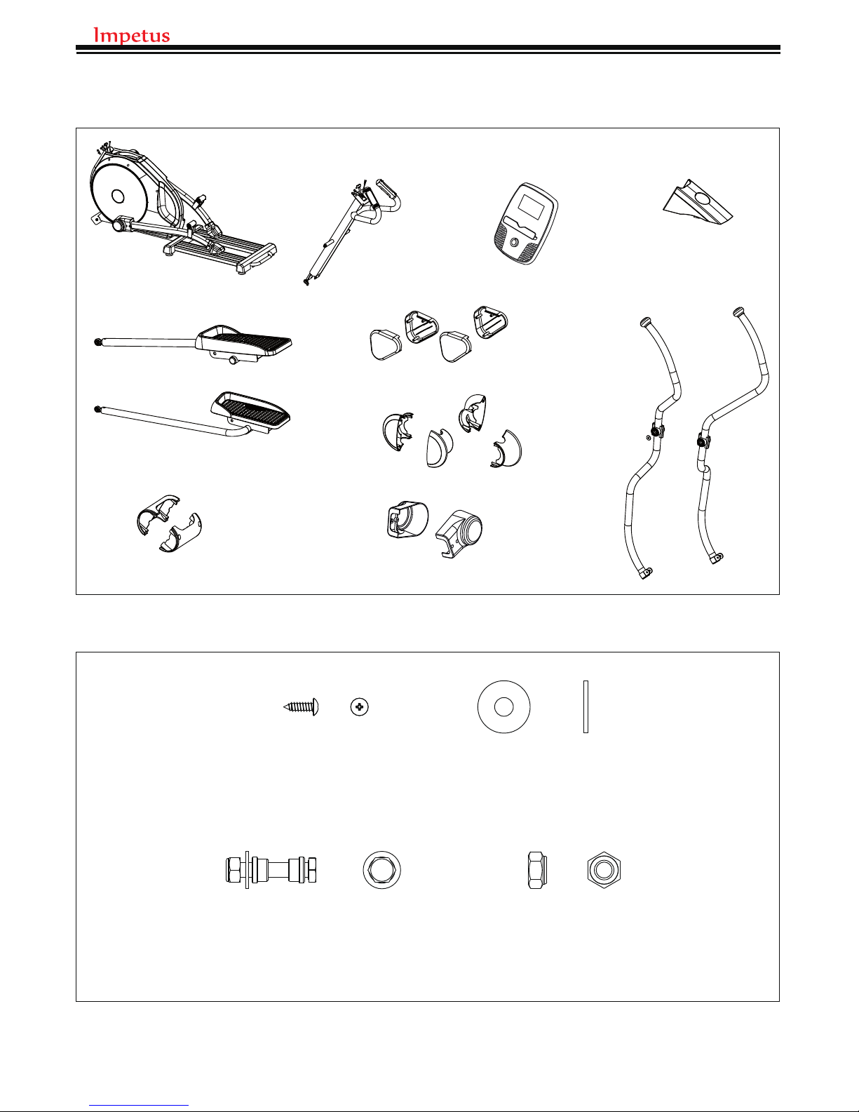
PACKING LIST
5
Main frame (#1A)
Handlebar post (#2A)
Water bottle holder (#86)
Connecting arm (#6A)
Connecting arm (#5A)
Right handlebar (#7A)
Left handlebar (#8A)
Console (#A1)
Post cover (52 & 53)
Upper handlebar cover (54 & 55)
Pedal arm cover (#51)
Lower handlebar cover (49 & 50)
HARDWARE PACK PACKING LIST
#84 M4*16mm Screw-8pcs #83 M10 Washer -2pcs
#75 M10 Locknut-2pcs#75 M8 Locknut-2pcs
#64 M8*40mm Screw-2pcs
#118 M8 Washer-2pcs
#30 Oil bearing-4pcs

ASSEMBLY INSTRUCTIONS
STEP 1
51
84
1. Attach the PEDAL ARM COVER (#51) to the PEDAL ARM using SCREW (#84).
2. Connect WIRES (#98 & B3) to WIRES (#B1).
3. Attach the HANDLEBAR POST (#2A) to the MAIN FRAME (#1A) using 2 SCREWS (#98),
2 SCREWS (#85) and 2 WASHERS (#99).
6
7
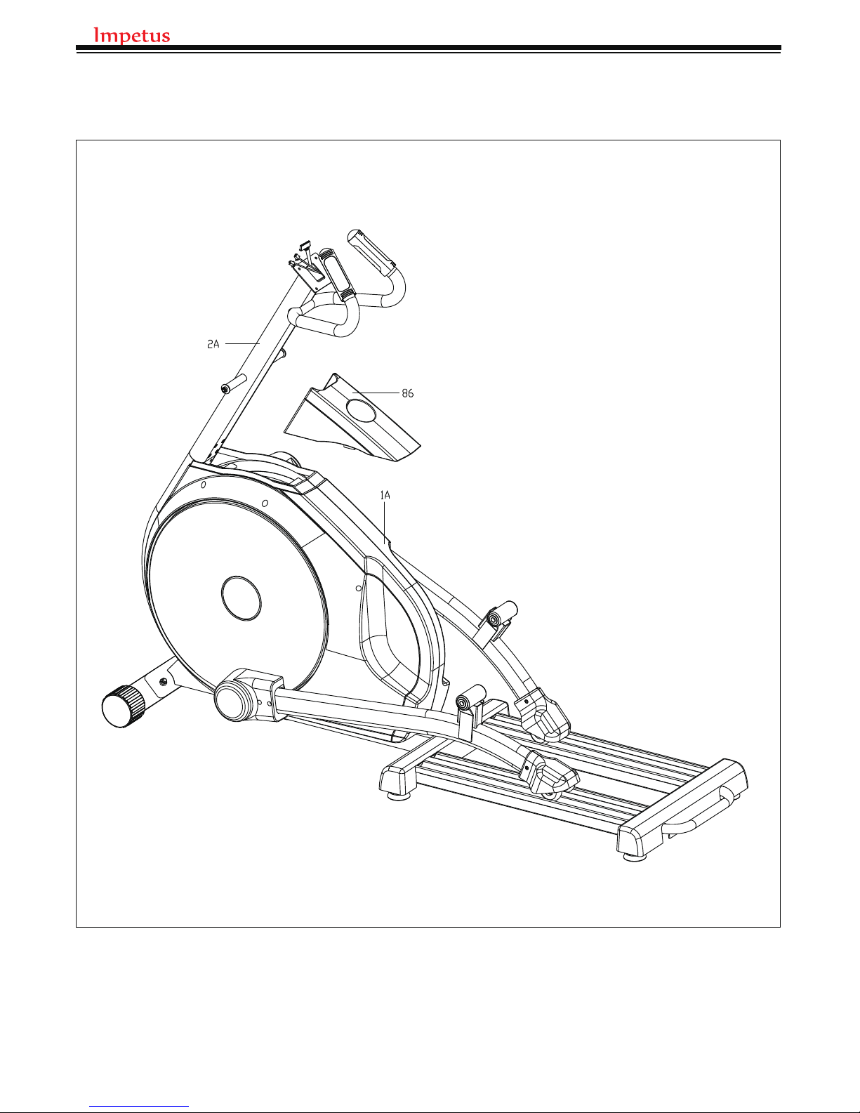
STEP 2
1. Attach the WATER BOTTLE HOLDER (#86) to the MAIN FRAME (#1A).

STEP 3
8
1. Remove the pre-installed SCREW (#71), WASHER (#80) and NUT (#76) from the
CONNECTING ARM (#5A).
2. Attach the CONNECTING ARM (#5A) to the PEDAL ARM (#4A) using a SCREW (#71),
a WASHER (#80) and a NUT (#76) removed earlier. Make sure BUSHING (#29) is attached on the
PEDAL ARM (#4A) as the graph shown before the assembly.
3. Repeat the above steps on the other side.
29
9
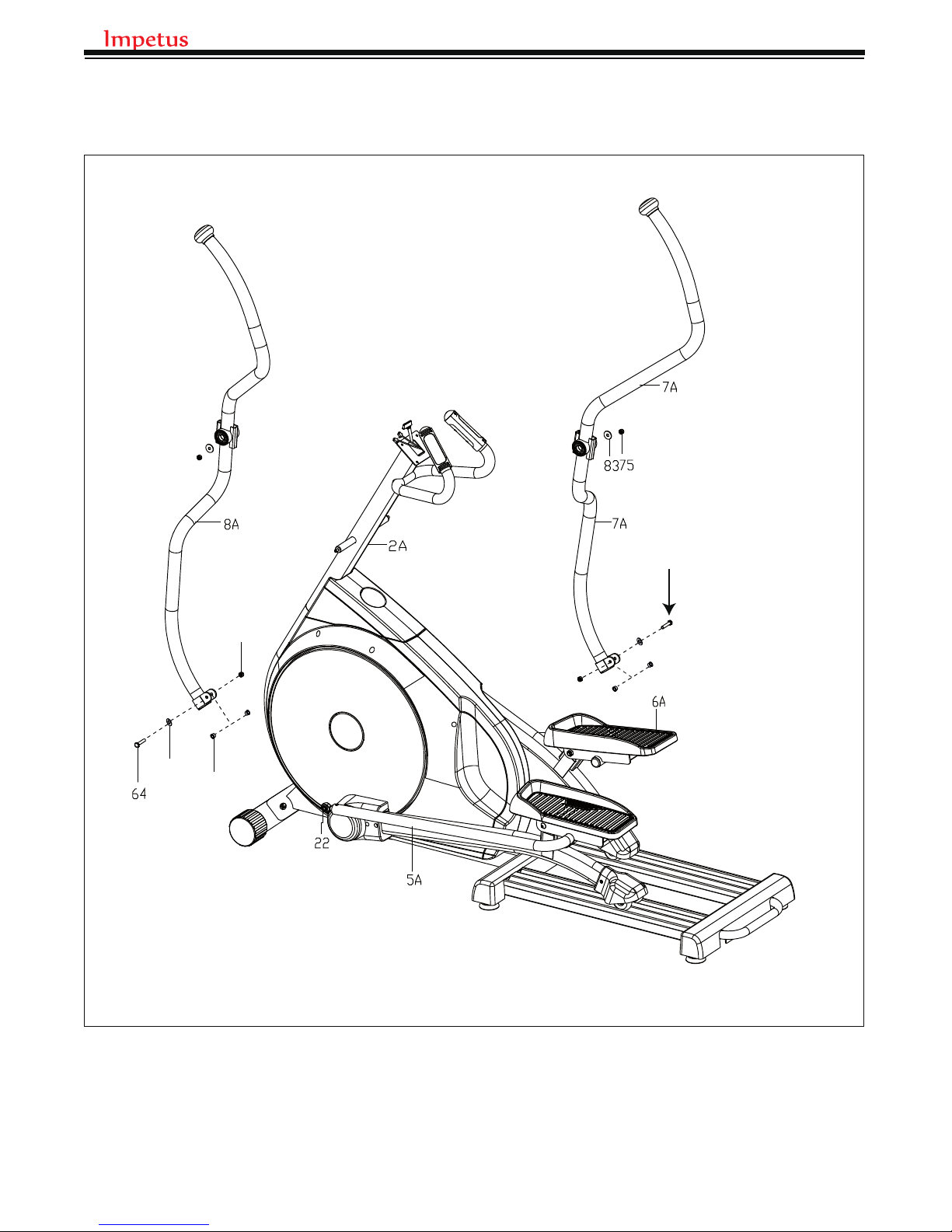
STEP 4
30
118
75
1. Attach the LEFT HANDLEBAR (#8A) to the HANDLEBAR POST (#2A) using 1 WASHER (#83)
and 1 NUT (#75).
2. Connect the lower LEFT HANDLEBAR (#8A) to the UNIVERSAL JOINT (#22) using 2 BUSHING
(#30), 1 WASHER (#118), 1 SCREW (#64) and 1 NUT (#75) as the picture shown.
3. !! Make sure the SCREW (#64) is tightened enough so there is no extra space inside.
4. Repeat the above steps on the other side.
!! MAKE SURE THIS SCREW
IS TIGHTENED
10
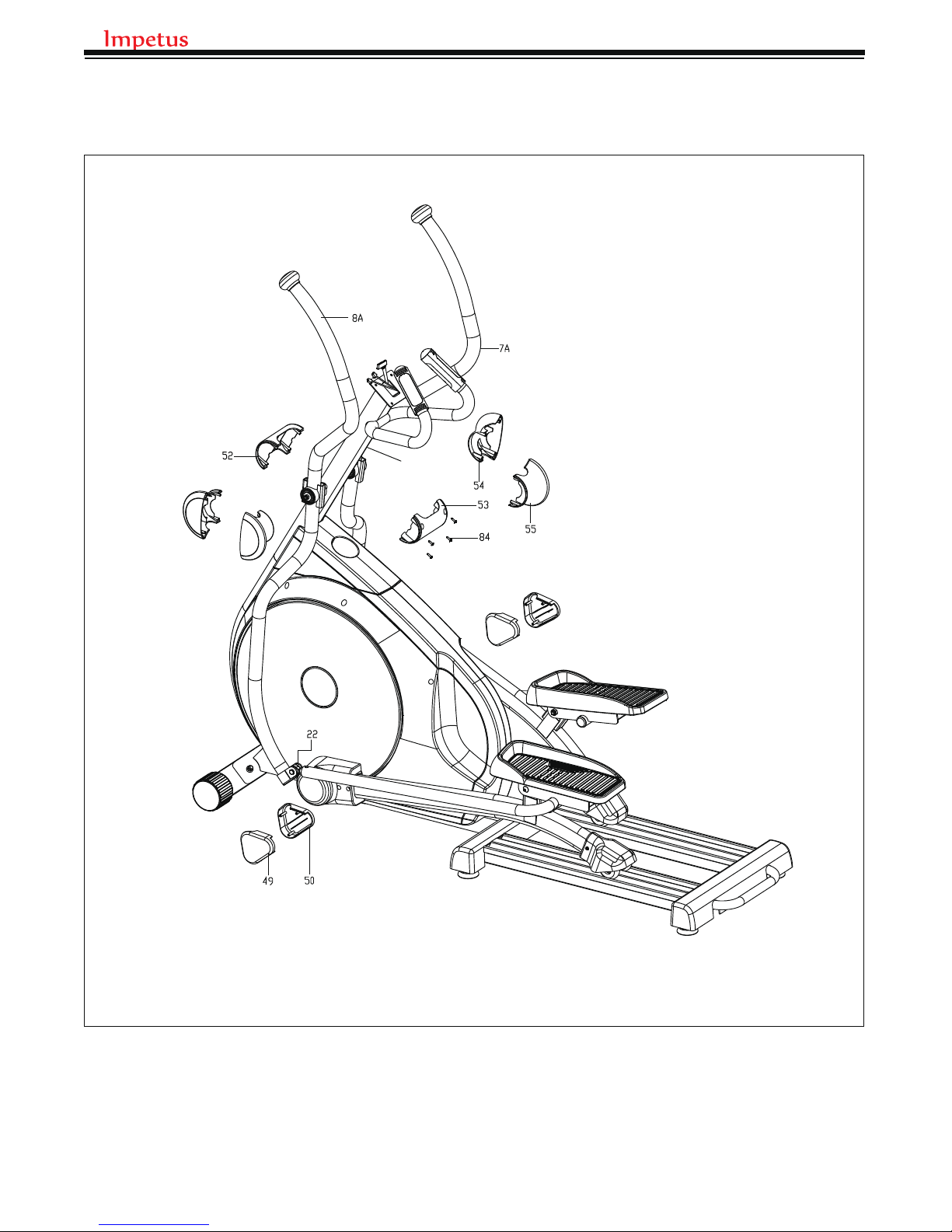
STEP 5
1. Attach the FRONT POST COVER (#52) and REAR POST COVER (#53) to the HANDLEBAR
POST (#2A) using 4 SCREWS (#84).
2. Attach the UPPER HANDLEBAR COVER ( #54 7) to the RIGHT HANDLEBAR (#7A).
3. Install the LOWER HANDLEBAR COVER (#49 & #50) at the UNIVERSAL JOINT (#22).
4. Repeat the above 2 steps on the other side.
2A

STEP 6
11
C
A1
1. Un-screw the top 2 SCREWS at the back of the CONSOLE (#A1), and loosen the bottom
2 SCREWS without removing them.
2. Slide the CONSOLE (#A1) onto the bracket as the graph shown.
3. Adjust the allignment of the CONSOLE (#A1), and tighten 4 SCREWS at the back of the
CONSOLE (#A1).
4. Insert 4 batteries into the CONSOLE (#A1) as the graph shown.

HOW TO MOVE THE TRAINER
HANDLE
TRANSPORT WHEEL
1. Hold the handle and lift the trainer up, so the transport wheels touch the floor.
2. Move the trainer to your designated position while lifting the trainer.
3. Carefully let down the trainer.
HOW TO ADJUST THE BALANCE OF THE TRAINER
Make sure the trainer is placed on the flat floor, and rotate the leveling foot clockwise or
counter-clock wise, so the leveling foot touches the floor.
12
ADDITIONAL INFORMATIOIN
1. The trainer requires an 9V, 1.3A adaptor.
2. When the trainer is idle for 4 minutes, it enters power save mode, and the workout result
is stored until the next workout.
3. To reset the console, replug in the adaptor.

EXPLODED VIEW
97
79
78
80
13

14
PART LIST
No. DESCRIPTION Q'ty No. DESCRIPTION Q'ty
1 MAIN FRAME 1 56 MIDDLE STABILIZER COVER 1
2 HANDLEBAR POST 1 57 REAR STABILIZER COVER 1
3 PEDAL ARM ( R ) 1 58 MOVING WHEEL COVER 1
4 PEDAL ARM ( L ) 1 59 PEDAL BASE ( L ) 1
5 CONNECTING ARM ( L ) 1 60 PEDAL BASE ( R ) 1
6 CONNECTING ARM ( R ) 1 61 HEX BOLT M6*20L 4
7 HANDLEBAR ( R ) 1 62 HEX BOLT M6*40L 1
8 HANDLEBAR ( L ) 1 63 HEX BOLT M10*35L 1
9 CRANK 2 64 HEX BOLT M8*40L 2
10 SLEEVE 2 65 HEX BOLT M10*40L 2
11 CRANK CONNECTING SHAFT 2 66 HEX BOLT M8*55L 8
12 PULLEY WHEEL 1 67 HEX BOLT M8*120L 1
13 LIFT HANDLE 1 68 ROUND HEAD ALLEN BOLT M10*35L 1
14 AXLE 1 69 ROUND HEAD ALLEN BOLT M8*45L 1
15 BEARING 6001ZZ 6001ZZ 4 70 HEX BOLT M12*95L 2
16 BEARING 6001ZZ 6201ZZ 4 71 BOLT Ø12*M10*134.7 2
17 BEARING 6203ZZ 6203ZZ 2 72 FLAT HEAD ALLEN BOLT M8*25 2
18 BEARING 6004ZZ 6004ZZ 8 73 HEX NUT M12 2
19 BEARING 6005ZZ 6005ZZ 2 74 HEX NUT M10 1
20 C-RING C25 2 75 NYLON LOCK NUT M8 18
21 C-RING C17 1 76 NYLON LOCK NUT M
10 7
22 UNIVERSAL JOINT M12 2 77 HEX W RENCH 15/19 1
23 IDLE ARM T6.0 1 78 NYLON LOCK NUT M6 5
24 IDLE SHAFT Ø20*35 1 79 WASHER Ø6.5*Ø12*T1.5 1
25 CAP Ø31.5*Ø30.5*17.3 2 80 W ASHER Ø10.5*Ø20*T2.0 3
26 C-RING C20 2 81 WASHER Ø10.5*Ø28*T2.0 2
27 LEVELING FOOT 4 82 W ASHER Ø8.4*Ø20*T2.0 20
28 SCREW M6*50.8*80 1 83 W ASHER Ø8.4*Ø28*T2.0 2
29 OIL BEARING Ø24*Ø17*Ø22*12 4 84 FLAT HEAD SELF-TAP SCREW M4*16 42
30 OIL BEARING Ø14*Ø12*Ø8*8.5Ø 4 85 FLAT HEAD ALLEN
BOLT M8*16 6
31 BEARING TUBE Ø42*20 4 86 WATER BOTTLE HOLDER 1
32 MOVING WHEEL Ø65*Ø12*24 4 87 ALLEN SCREW M6*10 8
33 CAP Ø64.5*42.5 2 88 FLAT HEAD SELF-TAP SCREW M4*10 10
34 SLIDING RAIL 678MM 2 89 ALLEN KEY M5/M6 1
35 MOVING WHEEL Ø97*126.5 2 90 WRENCH 1
36 SENSOR MAGNET 1 91 FLANGE NUT 3/8*26UNF*7T 2
37 C-RING C28 4 92 FLAT HEAD SELF-TAP SCREW M4*16 2
38 MAGNET 25*40*10 8 93 FRONT STABILIZER N76*T2.0*365 1
39 BELT 580-J6 1 94 BOLT M10*P1.5*88MM (L
37.5) 2
40 FORM GRIP 2 95 ARC WASHER Ø10.5*Ø23*T1.5 2
41 MAGNETIC FLYW HEEL 1 96 DOM NUT M10 2
42 CONTROLLER 1 97 FLAT KEY 6*6*20 2
43 CHAIN COVER ( L ) 1 98 FLAT HEAD ALLEN BOLT M8*65 2
44 CHAIN COVER ( R ) 1 99 WASHER Ø8.5*Ø17*1.3 4
45 DISK HOLE CAP 1 A1 CONSOLE 1
46 DISK 2 A2 TESNSION MOTOR 1
47 PEDAL ( L ) 1 A3 HAND PULSE HOLDER 2
48 PEDAL ( R ) 1 A4 ADAPTER 1
49 HAND RAIL DOWN COVER ( L ) 1 A5 SENSOR BLOCK 22.2*10*2.2 1
50 HAND RAIL DOWN COVER ( R ) 1 B1 COM
PUTER LOWER WIRE 800MM 1
51 PEDAL ARM FRONT COVER 2 B2 SENSOR WIRE 200MM 1
52 FRONT TUBE FRONT COVER 1 B3 UPPER WIRE 850MM 1
53 53 Front tube rear cover 1 1 B4 HAND PULSE WIRE 700MM*2 2
54 HAND RAIL MIDDLE COVER FRONT 1 B5 W IRE 850L(3P F+D.CSOCKET) 1
55 HAND RAIL MIDDLE COVER REAR 1

15
Suggested Stretches
The following stretches provide a good warm-up and cool-down. Move slowly
as you stretch.
Ham String Stretch
Sit with one leg extended. Bring the sole of the
opposite foot toward you, resting it against the
extended leg's inner thigh. Stretch toward your toe as
far as possible, hold for 15 counts, then relax. Repeat
three times for both legs. .
Stretches: Hamstring, Lower Back and Groin
Inner Thigh Stretch
Sit with the soles of your feet together and knees
pointing outward. Pull your feet as close into the groin
area as possible. Hold for 15 counts, then relax. Repeat
three times.
Stretches: Quadriceps and Hip Muscles
Toe Touches
Stand with your knees bend slightly, slowly bend forward
from the hips. Allow your back and shoulders to relax as
you stretch down toward your toes. Go as far as you can
and hold for 15 counts, then relax. Repeat three times.
Stretch: Hamstring, Back of Knees, Back
Quadriceps Stretch
Stand on one foot with one hand hold onto the wall to
balance, raise the other foot behind you, and pull up your
foot as close to your buttocks as possible. Hold for 15
counts, then relax. Repeat three times.
Stretch: Quadriceps muscles, Hip muscle
Calf/Achilles Stretch
Stretch: Lower legs, Achilles tendons, and Ankles
With one leg in front of the other and arms out, lean
against the wall. Keep your back leg straight and back
foot flat on the ground; then bend the front leg and lean
forward by moving your hips toward the wall. Hold, then
repeat on the other side. To cause even further
stretching the Achilles tendons, slightly bend back leg as
well.
WARM UP / COOL DOWN

This electronic product must not be disposed of in municipal
waste. To pre-serve the environment, this product must be
recycled after its useful life as required by law.
RECYCLING INFORMATION
Pleas e use recyc ling faci lities th at are authorized to collect this ty pe of waste
in your a rea. In doi ng so, you will help to conserve natural resour ces and
impro ve Europe an standa rds of envi ronment al protec tion. If you require more
infor mation ab out safe and correct disposal meth ods, plea se contac t your loca l
city office or th e establi shment wh ere you pur chased this prod
uct.
Inspect and tighten all parts of the exercise trainer regularly. Replace any worn parts
immediately.
To clean the exercise trainer, use damp cloth and a small amount of mild soap.
IMPORTANT: To avoid damage to the console, keep liquids away from the console and
keep the console out of direct sunlight.
CONSOLE TROUBLESHOOTING
Read console troubleshooting section in the console manual for assistance.
CLEANING & MAINTENANCE
16

USER MANUAL

SADRŽAJ
UVOD/VAŽNE INFORMACIJE 3
POPIS DIJELOVA 5
POPIS ALATA 5
UPUTE ZA SASTVALJANJE 6
KAKO POMICATI TRENAŽER 12
KAKO PODESITI BALANS TRENAŽERA 12
DODATNE INFORMACIJE 12
EXPANDIRANI POGLED 13
LISTA DIJELOVA 14
ZAGRIJAVANJE/HLAĐENJE 15
ČIŠĆENJE I ODRŽAVANJE 16

UVOD/VAŽNE INFORMACIJE
A. Uvod
Ovaj priručnik za korištenje sadrži upute za satavljanje, korištenje,
održavanje i sigurnosne mjere
B. Sigurnosne mjere
a. Pročitajte priručnik za korištenje i svu dodatnu literaturu.
b. Ova sprava je namijenjena za korištenje u zatvorenom prostoru
(kućna ili komercijalna upotreba)
c. Provjerite spravu prije korištenja kako bi bili sigurni da sus vi dijelovi
dobro pričvršćeni.
d. Postavite trenažer na ravnu podlogu.
e. Udaljte djecu mlađu od 14 godina i kućne ljubimce dok je trenažer u
funkciji
f. Ovaj trenažer sadrži pokretne dijelove. Držite djecu podalje od
sprave dok je u funkciji
g. Provjerite da je sve dobro podešeno kako biste izbjegli ozlijede.
h. Skinite sav nakit prije vježbanja.
i. Uvijek nosite prikladnu odjeću i obuću tijekom vježbanja. Nemojte
nositi labavu odjeću kako nebi zapela za spravu.
j. Zagrijte se 5 - 10 minuta prije svake vježbe i ohladite se 5 - 10 minuta
nakon treninga kako bi se vaš puls postepeno povisio i snizio kako bi
se smanjilo naprezanje mišića.
k. Nikad ne držite dah tijekom vježbanja.
l. Odmorite se između vježbi (48-72 sata). Mišići se izgrađuju i toniraju
za vrijeme odmora.
3

4
VAŽNO:
THE MAXIMUM RECOMMENDED WEIGHT CAPACITY FOR YOUR
EQUIPMENT IS 150 KGS.
UPOZORENJE:
Kontaktirajte obiteljskog liječnika prije početka s bilo kojim programom
vježbanja. Ako tijekom vježbanja osjećate vrtoglavicu ili bol, prestanite
s vježbanjem i kontaktirajte liječnika.
Sigurnost vase sprave se može održati na razini tako da se redovito
pregledava ima li oštećenja ili potrošenih dijelova. Sprava nije namijenjena za djecu mlažu od 14 godina.
VAŽNO:
Pažljivo pročitajte sve upute. Spravu sastavite prema uputama iz
priručnika. Posložite sve dijelove na pod i provjerite imate li sve potrebne dijelove prije nego što počnete sa sastavljanjem. U slućaju nesalganja, molimo kontaktirajte servis.

5
POPIS DIJELOVA
POPIS ALATA
Glavno kućište (#1A)
Pedala (#6A)
Pedala (#5A)
Pokrov glavnog stupa (52 & 53)t
Stup s ručkama (#2A)v
Konzol (#A1)
Pokrov donjih ručki (49 & 50)
Pokrov gornjih ručki (54 & 55)v
Pokrov šipke od pedale (#51)
Nosač bidona (#86)
Desna ručka (#7A)
Lijeva ručka (#8A)
#84 M4*16mm Vijak-8pcs
#83 M10 Šajbica -2pcs
#75 M8 Matica-2pcs #75 M10 Matica-2pcs
#64 M8*40mm Screw-2pcs
#118 M8 Šajbica-2pcs
#30 Uljni ležaj-4pcs

6
UPUTE ZA SASTAVLJANJE
KORAK 1
1. Spojite POKROV ŠIPKE OD PEDALE (#51) na ŠIPKU OD
PEDALE koristeći VIJAK (#84).
2. Spojite KABLOVE (#98 & B3) s KABLOVIMA (#B1).
3. Spojite STUP S RUČKAMA (#2A) na GLAVNO KUĆIŠTE (#1A)
pomoći 2 VIJKA (#98), 2 VIJKA (#85) i 2 ŠAJBICE (#99).

7
KORAK 2
1. Spojite NOSAČ BIDONA (#86) na GLAVNO KUĆIŠTE (#1A).

8
KORAK 3
1. Odvrnite VIJAK (#71), ŠAJBICU (#80) i MATICU (#76) sa ŠIPKE
(#5A).
2. Spojite ŠIPKU (#5A) s ŠIPKOM PEDALE (#4A) koristeći VIJAK
(#71), ŠAJBICU (#80) i MATICU (#76) koje ste ranije skinuli.
Budite sigurni da je (#29) spojen s ŠIPKOM PEDALE (#4A) kao na
slici.
3. Ponovite postupak za drugu stranu..

9
KORAK 4
1. Spojite LIJEVU RUČKU (#8A) s (#2A) koristeći 1 ŠAJBICU (#83) i
1 MATICU (#75).
2. Spojite DONJU LIJEVU RUČKU (#8A) s GLAVNIM ZGLOBOM
(#22) pomoću 2 (#30), 1 ŠAJBICOM (#118), 1 VIJKOM (#64) i 1
MATICOM (#75) kao na slici.
3. !! Provjerite da je VIJAK (#64) zategnut.
4. Ponovite za drugu stranu.
!! OVAJ VIJAK MORA
BITI ZATEGNUT

10
KORAK 5
1. Pričvrstite prednji dio poklopca (#52) i stražnji dio poklopca
(#53) za rukohvat (#2A) koristeći 4 vijka (#84).
2. Pričvrstite poklopac za gornji rukohvat (#54 i #55) na desni
rukohvat ( #7A).
3. Montirajte poklopac za donji dio rukohvata (#49 i #50) na
donji dio rukohvata.
4. Ponovite ova dva postupka na suprotnim stranama.

11
KORAK 6
1. Odvijte dva gornja vijka na stražnjoj strani konzole (#A1), i
olabavite dva donja vijka,
2. Pomaknite konzolu (#A1) na držač konzole ( kao na slici )
3. Podesite položaj konzole (#A1) i stegnite 4 vijka na poleđini
konzole (#A1)
4. Umetnite ,kao na slici

12
KAKO POMICATI TRENAŽER
KAKO PODESITI BALANS TRENAŽERA
DODATNE INFORMACIJE
1. Držite ručku i podignite trenažer,tako da kotačići na dnu
trenažera dodiruju površinu.
2. Pomaknite trenažer na određenu lokaciju
3. Oprezno spustite trenažer na tlo
RUČKA
TRANSPORTNI
KOTAČ
Budite sigurni da su stabilizatori i trenažer na ravnoj površini, i
da dodiruju pod.
1.Eliptični trenažer zahtjeva 9.V, 1.3A adapter
2.Kada je trenažer 4 minute izvan funkcije, ulazi u program
čuvanja baterije i isključuje se, a svi podatci prošlog vježbanja su
spremljeni
3.Da bi ugasili trenažer,isključite adapter

13
EXSPANDIRANI POGLED
9
7
79
78
80

14
LISTA DIJELOVA
No. DESCRIPTION Q'ty No. DESCRIPTION Q'ty
1 MAIN FRAME 1 56 MIDDLE STABILIZER COVER 1
2 HANDLEBAR POST 1 57 REAR STABILIZER COVER 1
3 PEDAL ARM ( R ) 1 58 MOVING WHEEL COVER 1
4 PEDAL ARM ( L ) 1 59 PEDAL BASE ( L ) 1
5 CONNECTING ARM ( L ) 1 60 PEDAL BASE ( R ) 1
6 CONNECTING ARM ( R ) 1 61 HEX BOLT M6*20L 4
7 HANDLEBAR ( R ) 1 62 HEX BOLT M6*40L 1
8 HANDLEBAR ( L ) 1 63 HEX BOLT M10*35L 1
9 CRANK 2 64 HEX BOLT M8*40L 2
10 SLEEVE 2 65 HEX BOLT M10*40L 2
11 CRANK CONNECTING SHAFT 2 66 HEX BOLT M8*55L 8
12 PULLEY WHEEL 1 67 HEX BOLT M8*120L 1
13 LIFT HANDLE 1 68 ROUND HEAD ALLEN BOLT M10*35L 1
14 AXLE 1 69 ROUND HEAD ALLEN BOLT M8*45L 1
15 BEARING 6001ZZ 6001ZZ 4 70 HEX BOLT M12*95L 2
16 BEARING 6001ZZ 6201ZZ 4 71 BOLT Ø12*M10*134.7 2
17 BEARING 6203ZZ 6203ZZ 2 72 FLAT HEAD ALLEN BOLT M8*25 2
18 BEARING 6004ZZ 6004ZZ 8 73 HEX NUT M12 2
19 BEARING 6005ZZ 6005ZZ 2 74 HEX NUT M10 1
20 C-RING C25 2 75 NYLON LOCK NUT M8 18
21 C-RING C17 1 76 NYLON LOCK NUT M
10 7
22 UNIVERSAL JOINT M12 2 77 HEX WRENCH 15/19 1
23 IDLE ARM T6.0 1 78 NYLON LOCK NUT M6 5
24 IDLE SHAFT Ø20*35 1 79 W ASHER Ø6.5*Ø12*T1.5 1
25 CAP Ø31.5*Ø30.5*17.3 2 80 W ASHER Ø10.5*Ø20*T2.0 3
26 C-RING C20 2 81 W ASHER Ø10.5*Ø28*T2.0 2
27 LEVELING FOOT 4 82 WAS HER Ø8.4*Ø20*T2.0 20
28 SCREW M6*50.8*80 1 83 WASHER Ø8.4*Ø28*T2.0 2
29 OIL BEARING Ø24*Ø17*Ø22*12 4 84 FLAT HEAD SELF-TAP SCREW M4*16 42
30 OIL BEARING Ø14*Ø12*Ø8*8.5Ø 4 85 FLAT HEAD ALLEN
BOLT M8*16 6
31 BEARING TUBE Ø42*20 4 86 WATER BOTTLE HOLDER 1
32 MOVING WHEEL Ø65*Ø12*24 4 87 ALLEN SCREW M6*10 8
33 CAP Ø64.5*42.5 2 88 FLAT HEAD SE LF-TAP SCREW M4*10 10
34 SLIDING RAIL 678MM 2 89 ALLEN KEY M5/M6 1
35 MOVING WHEEL Ø97*126.5 2 90 WRENCH 1
36 SENSOR MAGNET 1 91 FLANGE NUT 3/8*26UNF*7T 2
37 C-RING C28 4 92 FLAT HEAD SELF-TAP SCREW M4*16 2
38 MAGNET 25*40*10 8 93 FRONT STABILIZER N76*T2.0*365 1
39 BELT 580-J6 1 94 BOLT M10*P1.5*88MM (L
37.5) 2
40 FORM GRIP 2 95 ARC WASHER Ø10.5*Ø23*T1.5 2
41 MAGNETIC FLYWHEEL 1 96 DOM NUT M10 2
42 CONTROLLER 1 97 FLAT KEY 6*6*20 2
43 CHAIN COVER ( L ) 1 98 FLAT HEAD ALLEN BOLT M8*65 2
44 CHAIN COVER ( R ) 1 99 WASHER Ø8.5*Ø17*1.3 4
45 DISK HOLE CAP 1 A1 CONSOLE 1
46 DISK 2 A2 TESNSION MOTOR 1
47 PEDAL ( L ) 1 A3 HAND PULSE HOLDER 2
48 PEDAL ( R ) 1 A4 ADAPTER 1
49 HAND RAIL DOWN COVER ( L ) 1 A5 SENSOR BLOCK 22.2*10*2.2 1
50 HAND RAIL DOWN COVER ( R ) 1 B1 COM
PUTER LOWER WIRE 800MM 1
51 PEDAL ARM FRONT COVER 2 B2 SENSOR WIRE 200MM 1
52 FRONT TUBE FRONT COVER 1 B3 UPPER WIRE 850MM 1
53 53 Front tube rear cover 1 1 B4 HAND PULSE WIRE 700MM*2 2
54 HAND RAIL MIDDLE COVER FRONT 1 B5 W IRE 850L(3P F+D.CSOCKET) 1
55 HAND RAIL MIDDLE COVER REAR 1

15
ZAGRIJAVANJE/HLAĐENJE
Iduće vježbe su odlične za zagrijavanje i istezanje nakon treninga, pokrete
izvodite polako i do granice boli.
Istezanje zadnje lože:
Sjednite sa jednom ispruženom nogom. Stopalo druge
noge primaknite prema bedru ispružene noge. Pokušajte
rukama dotaknuti prste ispružene noge,ostanite u toj
poziciji 15 sekundi i odmorite. Ponovite vježbu tri puta za
svaku nogu.
Istezanje unutarnjeg bedra :
U sjedećem položaju spojite stopala i laktovima lagano
pritišćemo koljena.Povucite stopala što je moguće bliže
preponama. Ostanite u toj poziciji 15 sekundi pa
odmorite.Odradite tri serije ove vježbe.
Dodirivanje prstiju :
Stanite sa lagano savijenim koljenima, lagano se iz kukova
naginjemo naprijed. U ovoj poziciji pokušavamo rukama
dohvatiti nožne prste. Ostajemo u toj poziciji 15 sekundi.
Ponavljamo vježbu tri puta.
Istezanje kvadricepsa :
Stanite jednom nogom pridržavajući se rukom od zid
radi bolje ravnoteže. Primite rukom drugu nogu i što
više je primaknite prema mišićima stražnjice. Držite 15
sekundi pa odmorite. Odradite ovu vježbu tri puta.
Istezanje listova :
Držimo se rukama za zid a jednu nogu pružamo naprijed
i lagano savijamo u koljenu. Kukove izbacujemo prema
naprijed i zadržavamo poziciju. Ostajemo u poziciji 15
sekundi nakon čega mjenjamo nogu. Radimo 3 serije za
svaku nogu.

16
ČIŠĆENJE I ODRŽAVANJE
Pregledajte i učvrstite sve djelove eliptičnog trenažera. Ako prim-
jetite da neki dio sprave nije učvršćen zamjenite ga odmah.
Za pranje sprave koristite vlažnu tkaninu i malu količinu sredstva
za čišćenje.
VAŽNO :
Da bi izbjegli oštećenje sprave, držite tekućinu podalje od sprave i
držite spravu dalje od izravne sunčeve svjetlosti
Recikliranje :
Ova električna sprava mora biti reciklirana i skladištena u poseb-
nim uvjetima.
Da bi sačuvali prirodu, nakon životnog roka sprave po zakonu
istu moramo reciklirati na ispravan način.
 Loading...