

Page 1

Page 1
Installation and Maintenance Instructions
ZenFire
Model : X
PLEASE READ THESE INSTRUCTIONS CAREFULLY
AND RETAIN FOR FUTURE REFERENCE
This electric fire has been made with great care. Here are some instructions including cleaning
and maintenance, which will help you keep your fire in good condition for many years. If you
experience any parts or service problems contact your retailer . This appliance is not intended
for use by persons (including children) with reduced physical, sensory or mental capabilities, or
lack of experience and knowledge, unless they have been given supervision or instruction concerning use of the appliance by a person responsible for their safety. Children should be supervised to ensure that they do not play with the appliance.'
This is an amendment to the standard and now applies to all EN60335 items
WARNING
TURN OFF APPLIANCE AT MAINS AND UNPLUG FROM SOCKET OR REMOVE
FUSE FROM SWITCHED ISOLATOR BEFORE REPLACING LAMP
LAMPS MAY BE HOT—ALLOW TO COOL BEFORE REMOVING LAMP GUARD
IMPORTANT: Use only fixings provided to attach the fire front to the back , the
fire to the plinth and the log guard to the fire back see pages 4 and 5
Created and Manufactured in the UK
by
Imperial Fires Ltd
+44(0)1527577800
www.imperial-fires.co.uk
Patent applied for
Zen installation Instructions I00469: Issue c : Widney leisure Ltd 2008 ©
The product complies with the European Safety Standards EN 60335 -1,EN60335-2-30 and the essential requirements of EEC Directives 73/23 and 89/336
Page 2

Page 2
THIS APPLIANCE MUST BE EARTHED
Check that the voltage stamped on the rating label of your fire is the same as your house electricity supply which must be AC (alternating current).
The mains cord of the fire has a UK type plug fitted with a 13amp fuse. When replacing a fuse,
use a 13amp fuse approved to BS 1362. The fuse cover of a moulded on plug must be refitted
when changing the fuse. Should the fuse cover become lost, the plug must not be used until the
correct replacement fuse cover is obtained from your service agent.
The wires in the mains supply cord are coloured in accordance with the following code: Green
and Yellow = Earth, Blue = Neutral, Brown = Live.
If your fire is fitted with a moulded on mains plug which is not suitable for the socket outlets in
your home, the plug must be cut off and an appropriate one fitted, OR IF DESIRED THE FIRE
CAN BE FITTED WITH A FUSED SWITCH ISOLATOR.
Note: A plug cut off from a flexible cord will give a shock hazard if inserted in a 13 amp socket
elsewhere in the house. To avoid this it should be disposed of immediately.
If you are fitting an alternative type of plug then the colours of the wires in the mains cord may
not correspond with the identifying markings on the plug terminals. In this case proceed as follows:
The wire which is coloured Green/Yellow must be connected to the terminal in the plug which is
marked by the letter E or by the earth symbol
or coloured Green or Green/Yellow. The wire which is coloured Blue must be connected to the
terminal in the plug which is marked by the letter N or coloured Black. The wire which is coloured
Brown must be connected to the terminal in the plug which is marked by the letter L or coloured
Red.
•
Always install the fire so that the plug is accessible.
•
Do not cover or hang clothes, towels etc over or near the heater as this could cause over
heating and possible damage.
•
The heater should not be used immediately below a socket outlet.
•
Do not use in the immediate surroundings of a bath, shower or near any source of
Water.
•
Ensure that sufficient cable length is fitted to enable the mains socket to be re moved
from the appliance without stretching.
Do not use this heater with an external programme controller, thermal control, timer or any other
device which switches the heater on automatically as a fire risk may occur if the heater has been
accidentally covered or moved
HARD WIRING THE FIRE.
IF DESIRED THE FIRE CAN BE HARD WIRED TO A SWITCHED FUSED ISOLATOR.
IF A SWITCH FUSED ISOLATOR IS USED ENSURE THAT THE FUSE IN THE ISOLATOR IS
FITTED W ITH A FUSE RATED AT 13AMP TO BS1362. It is recommended that this work be
undertaken by a competent engineer
UNPACKING ELECTRICAL INSTALLATION. AND GENERAL SAFETY
General
Unpack the heater carefully and retain the packaging for possible future use, in the event of
moving or returning the fire to your supplier. The fire incorporates a flame effect, which can be
used with or without heating, so that the comforting effect may be enjoyed at any time of the
year. Using the flame effect on its own only requires little electricity.
Before connecting the heater check that the supply voltage is the same as that stated on the
heater.
Please note: Used in an environment where background noise is very low, it may be possible to
hear a sound which is related to the operation of the flame effect. This is normal and should
not be a cause for concern.
Page 3
Page 3
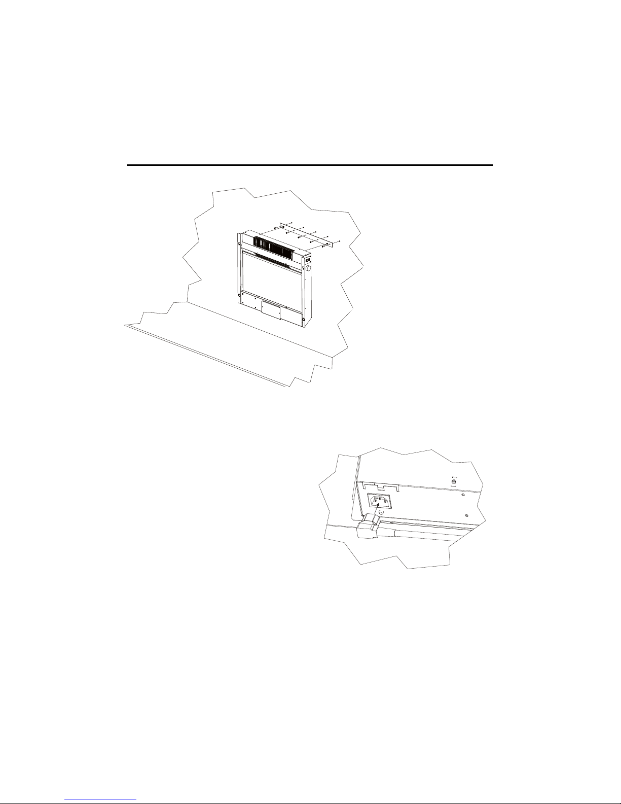
ELECTRIC FIRE - WALL HANGING INSTALLATION INSTRUCTIONS.
1) Draw a line 600mm -> 800mm from Floor that is parallel to the floor level to a
spirit level - (height according to Customer preference)
2) Mark fixing holes through hanger bar and drill holes to suit wall fixings and
screws.
3) Fix Hanger bar to Wall using suitable
fixings.
4) Hand tighten Hanger screws that are
fitted to Hanger bar threaded insert so
as to just make contact with wall (approx 5mm of thread should be visible behind the screw head).
5) The main Chassis of the Fire is now
ready to be fitted.
6) Connect the mains cord to the fire as
shown in figure 2
7) Offer the fire Chassis up to the Hanger bracket paying attention to where the
Key hole slots are in the Fire back. The Chassis should be located on the
thread of the screw, not the threaded insert.
6) The Fascia and Log Guard may now be fixed to the fire chassis following the
instructions on page 5.
Wall fixing -The appliance
should be securely fixed to the
wall using wall plugs and
screws suitable to fit the 5mm
hole in the hanging bar
Note – for studded walls special fasteners are required,
.
FIG 2
HANGER
FIG 1
Page 4

Page 4
INSTRUCTIONS FOR FITTING THE FREE-STANDING PLINTH.
ENSURE THAT THE FIRE IS DISCONNECTED FROM THE MAINS
1) Prepare the Fire chassis for insertion of the Plinth uprights, The best position to do this in
is with the Fire chassis on its face placed on a clean non-scratch surface,
2) Slide the fire back over the uprights of the plinth into the back of the fire as shown in Fig 3
until the threads are visible through the holes in the fire back, it may be necessary to adjust slightly to insert the M4 screws provided. Tighten the screws and anti-vibration
washers up fully.
3) Stand the Fire upright in its desired location and fit the Fascia frame, Log guard and Logs
in accordance with instructions provided on page 5
4) The fire should be positioned on a firm flat and level base.
Note: If the stand is to be used the Mains cable plug must be inserted into the mains connector on the underside of the appliance as shown on Page 3 Fig 2 before the free standing plinth is Fitted. Ensure that the mains plug is not connected to the mains supply before the Free standing plinth is fitted.
Plinth upright insertion
points
FIG 3
Page 5

Page 5
1) To fit the Fascia frame, Remove the transit tape from the hanging screws, ensure that
the hanging screws in the rear of the frame are not screwed in tightly—a gap must be
maintained between the screw head and the fire front to enable the screw to slide into the
fixing hole.
2) Position the fire front so that the hanging screws either side line up with the keyhole slots
in the Fire chassis, the frame should then be gently pushed down fully to engage the
smaller diameter of the keyhole. The bottom of the frame will then locate onto the magnets at the bottom of the chassis.
3) The Log guard may now be fitted. Remove the log guard screws from the fire back as
shown in figure 4—remove transit tape if fitted. Place the log guard into the gap at the
bottom edge of the screen with the bars facing forward as shown. Using the 2—M4
screws removed from the fire back, fix the log guard to the fire back—do not over tighten.
IMPORTANT—use only screws provided.
4) The Logs may now be placed between the screen and Log guard bars as indicated on
page 6.
Replacement of Lamp: The log guard must be removed by unscrewing the two screws indicated
in the above drawing before removing the fire front refer to page 8 for detailed instructions
ELECTRIC FIRE - FITTING THE FASCIA FRAME AND LOG GUARD.
FIG 4
Page 6

Page 6
ELECTRIC FIRE - FITTING THE LOGS
Ensure that the base of the log
touches the fuel support base
Ensure that the base of the log
touches the fuel support base
Ensure that the base of the log
touches the fuel support base
Finished Effect
Place left Log on the left hand side of the Log
guard ensure that the base of the log sits onto the
fuel support as shown
Place right log on the right hand side of the Log
guard ensure that the base of the log sits on the
fuel support as shown.
Place centre Log in the centre of the two other
logs
Replacement of Lamp: Remove logs from log guard in reverse order to the instructions detailed
above - refer to page 10 for detailed instructions
Page 7

Page 7
Battery information
1. Slide open the battery cover on the back of the remote control
2. Install LRV08 12v battery into the remote control
3. Replace the battery cover.
Discard leaky batteries
Dispose of batteries in the proper manner according to provincial and local regulations.
Any battery may leak electrolyte if mixed with a different battery type, if inserted incorrectly, if all
the batteries are not replaced at the same time, if disposed of in a fire, or if an attempt is made to
charge a battery not intended to be recharged.
Control Reset.
If the remote control fails to operate the fire first ensure that the batteries are in good condition.
Switch the mains switch on the side of the fire to Off
Turn the thermostat to position O
Switch the isolator or wall switch to OFF.
Switch wall switch or isolator on
Switch Mains switch on side of fire on
Press Button 1 on the handset.
Thermostat
In order to maintain a certain room temperature, set the controller to either first or second heat
setting. Operate the appliance until the required room temperature is reached. (Note in cold
conditions it may be necessary to operate the heater with both heat setting switch on to reach
the desired room temperature). Set back the thermostatic controller until the appliance switches
off with an audible ‘click’. This temperature will be kept almost constant by the thermostatic control switching on and off automatically.
Please note that the appliance can only be switched on when the thermostat setting is higher
then the room temperature.
Page 8

Page 8
ELECTRIC FIRE - USING THE REMOTE CONTROL.
Switching On the Fire:
Ensure that the fire is plugged in and switched on at the
wall switch or isolator.
The fire has a master power switch located on the right
hand side of the fire behind the front frame. To operate
switch the rocker switch to the forward position—The
switch will light up if power is available. ( see Figure 1)
Remote Control Operation - see Fig 5
1. Flame effect On
2. Heater 1st heat setting On and all heat off
3. Heater and Flame effect Off
4. Heater 2nd Heat setting On and Off
5. Flame Effect Brightness
To Turn the Fire on Press Button 1. This will Start
the flame Effect.
To Adjust the flame effect see section on flame
effect.
To Operate the fire on minimal heat setting
press button 2 and adjust thermostat located by the
main switch see fig 5 to desired heat
setting.
For full heat setting press button 4 after pressing
button 2( Quick Warm up)
To turn the heat to lower setting Press button 4
again
To turn heat off Press Button 2.
Flame effect adjustment.
The flame effect on this appliance is adjustable for intensity. Press and release button 5 and the
flame effect intensity will modulate between off and full brightness. When the desired intensity is
reached press button 5.
Switching Fire off
Press button 3
Turn Master switch See Fig 5 to Off.
NOTE: Always switch the appliance off with the remote control first.
Switch
1
2
3
4
5
Remote control
The maximum range of use is ~ 7 metres.
Warning: It takes time for the receiver to respond to the transmitter.
Do not press the buttons more than once within two seconds for correct operation.
FIG 5
Page 9

Page 9
ZENFIRE Flame Effect
Your new fire has a unique flame effect which simulates a real burning fire. The Flame Effect is
designed to be as random as possible to create a realistic effect of flames burning as seen in a
real fire.
The nature of the effect is to speed up and slow down at random intervals—this creates more
realism.
On first starting it may be noticed that the effect is slower with less flickering—the longer the fire
is left on the flickering effect will become faster, but periodically it may reduce to a glow for a
short period.
The light effect is adjustable as detailed on page 8 of these instructions. When first starting the
light effect is set at
approximately 70% of full glow for full 100% glow press and release button 1 and then press
and release again within 5 seconds of first pressing button 1
Page 10

Page 10
LAMP REPLACEMENT
WARNING
TURN OFF APPLIANCE AT MAINS AND UNPLUG FROM SOCKET OR REMOVE FUSE
FROM SWITCHED ISOLATOR BEFORE REPLACING LAMP
LAMPS MAY BE HOT—ALLOW TO COOL BEFORE REMOVING LAMP GUARD
1. Remove the log sets as detailed on page 6 then remove the log guard as detailed on
page 5.
2. Remove the fire front by pulling forward from
the bottom and sliding upward and outward
3. Remove the two screws as indicated in fig 6
and remove the cover by pulling forward.
Note when the plinth is fitted the cover slides
between the gap in the plinth and the bottom
of the fire
4. Unscrew the lamp in a counter clockwise
direction—Ensure that the lamp is cool
before touching.
5. To replace reverse the above procedure
IMPORTANT INFORMATION
SAFETY CUT- OUT
The heating element is fitted with a cut-out which will switch off
the fire if it overheats. Should this occur follow the points below.
1. Switch the fire off at the wall outlet
2. Ensure that there are no obstructions in or around the
air inlet or outlet see Fig, 7
3. After approximately 5 minutes switch the fire on.
(The thermal cut-out will take approximately 5 minutes to reset
once activated—do not switch the fire on until the above
checks have been completed.
4. If the fault persists contact your retailer.
CLEANING AND MAINTENANCE.
IMPORTANT NOTICE.
Your electric heater operates using a rotary fan. Due to the working nature of this fan it is inevitable that a build up of LINT, or general house dust (i.e.) carpet fibres or animal fur etc, will from
time to time accumulate around the inlet and outlet grills at the top and front of the fire. Therefore
it is recommended that regular cleaning of this area is undertaken using a standard vacuumed
cleaner attachment .
For safety reasons please ensure that the fire is switched off and has had time to cool down before cleaning.
General Cleaning.
The fire should be cleaned with an antistatic cloth to prevent dust being attracted to the high
gloss surfaces of the fire.—do not use polish.. For difficult to remove marks such as finger marks
it is recommended that a chamois leather slightly damp is used.
Note. The high gloss finish on the front of the fire is resistant to normal cleaning DO NOT USE
abrasive materials .
SERVICE _ MAINTENANCE AND CLEANING
FIG 6
FIG 7
AIR INLET
Page 11

Page 11
Fault Customer Action
1
Fire does not turn on
when button 1 on the
remote control is
pressed
Check the power switch is on ( the switch should light up) if no
check fuse in plug or wall socket.
Check batteries in remote control
Reset the control system see page 8
Check to ensure that remote control frequency indicated on
the data label is the same setting as the dial indicator on the
rear of the remote handset If the above checks have been done and the fire still does not
work contact your retailer and Report Fault Code E7
2
The fire flame effect is
working but there is no
heat when either button
2 or 4 on the remote is
pressed.
Check to ensure thermostat is turned to full.
If the fire does not work after turning thermostat to full check
steps in section 1.
If the above checks have been done and the fire still does not
work contact your retailer and Report Fault Code E5
3
The fire turns on and
the heater works but
the flame effect does
not work
Check the lamp see page 9
If the above checks have been done and the fire still does not
work contact your retailer Report Fault Code E6
4
The fire is turned to
heat the room but after
a few minutes the fire
turns off.
The fire is fitted with a thermal cutout which is designed to protect the product from overheating. Check to ensure that all air
vents are clear of dust and obstructions. OK
Does the fire restart without removing plug? Yes /No
If yes there is a fault with the product. contact your retailer
Report Fault Code E1
5
The Flame is noisy Turn the fire off on the remote control then press button I to
operate the flame fan only.
Is the fire noisy? Yes/ No
If yes then try to identify the type of noise egg is it a fan noise
or something else – The flame fire will exhibit a blowing fan
like noise when the effect is on.
Contact your retailer Report Fault Code E3
6
The fire is noisy when I
turn the heater on
Turn the fire off from the remote control and then press button
1 If the fire does not emit the noise then turn on the heat settings by pressing button 2. If the fire becomes noisy try to identify the type of noise and contact your retailer Report Fault
Code E2
Page 12

Page 12
The Symbol shown here and on the product indicates that the product is classed as Electrical or Electronic Equipment and should not be disposed with other household or commercial waste at the end of its working life.
Product Disposal Instructions: When you have no further use for the product, please dispose the product at your local authorities recycling
centre. For business users Do No dispose of the product with normal commercial waste.
Short Parts List Item Part Number Quantity per Fire
Light Lamp 25w Max SES - Clear
I00456
1
Log Pack Set of 3
I00474
1
Remote Control
I00461
1
Remote Control Battery LVR 08 or equivalent
I00514
1
Mains Cord UK Plug MAINS CORD: If the mains supply cord is damaged it
must be replaced by a competent electrician or similarly qualified person.
I00467
1
TECHNICAL SPECIFICATION
Dimensions Height
mm
Width
mm
Depth
mm
With Plinth
mm
512 803 97 620 high x 200 deep
Technical Specification
Frequency 50Hz
Voltage 220~240v A.C.
Power Input 1538 w
Remote Control Radio Frequency Control: Max Range 7 metres @433.92 MHz
Max RF output Power 0.31mW ERP—Preset
Dimensions without plinth fitted Dimensions with plinth fitted
Page 13

Page 13
 Loading...