

1
Installation and Maintenance Instructions
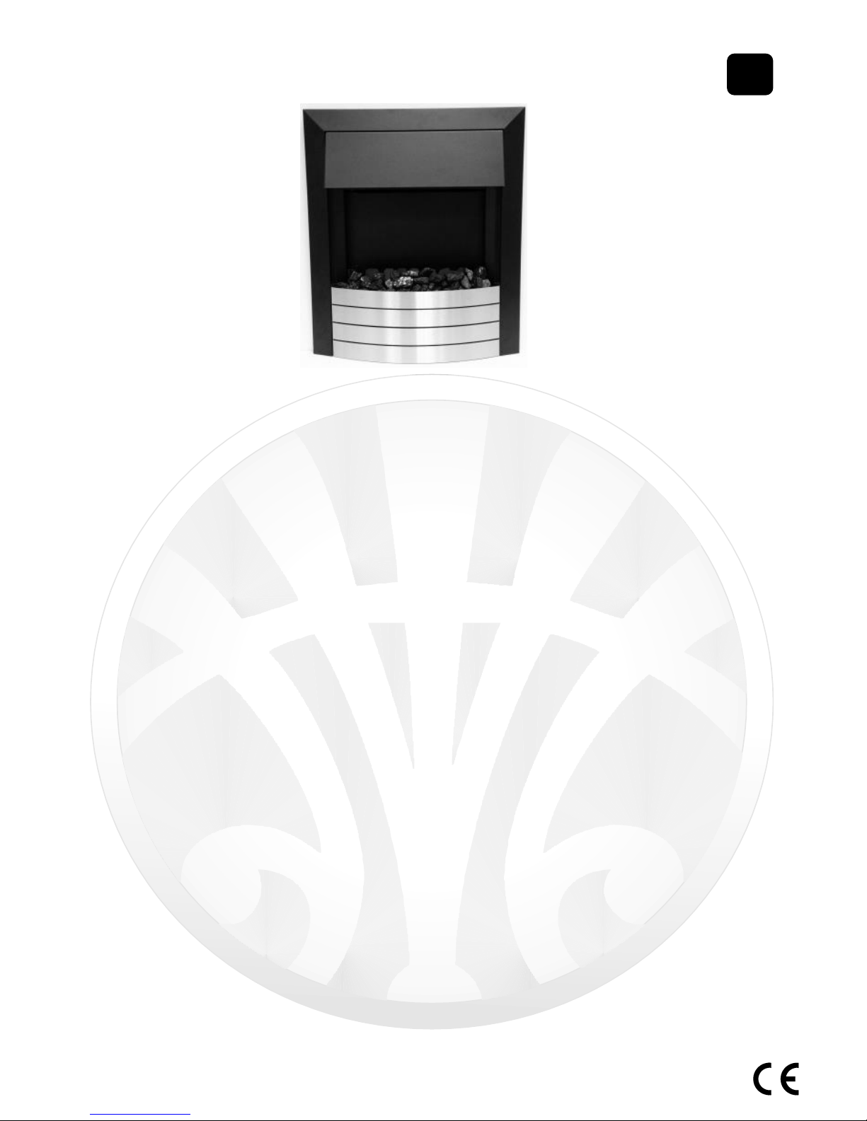
TF4 Electric Fires
PLEASE READ THESE INSTRUCTIONS CAREFULLY AND
RETAIN FOR FUTURE REFERENCE
Your IMPERIAL electric fire has been made with great care. Here are some instructions
including cleaning and maintenance, which will help you keep your fire in good condition
for many years. If you experience any parts or service problems contact either your
retailer or IMPERIAL FIRES LIMITED.
This appliance is not intended for use by persons (including children) with reduced
physical, sensory or mental capabilities, or lack of experience and knowledge, unless they
have been given supervision or Instruction concerning use of the appliance by a person
responsible for their safety. Children should be supervised to ensure that they do not play
with the appliance.
This is an amendment to the standard and now applies to all EN60335 items.
Created and Manufactured in the UK By
Imperial Fires Ltd
St Marys Road, Nuneaton, Warwickshire, CV11 5AU UK
TEL 02476 377550; FAX 02476 388578
Web: imperial-fires.co.uk
Email: sales@widney-leisure.co.uk
The product complies with the European Safety Standards EN 60335 -1,EN60335-2-30 and the essential requirements of EEC Directives 73/23 and 89/336
Part No I01372 issue C
GB
IE
IMPERIAL ELECTRIC FIRES

2
YOUR FIRE
TF4 Fires are Visual effect fires with LED lighting and remote control. They are available
with several different facia trims and frets.
The general fitting instructions refer to all models.
SECTION 1: UNPACKING, ELECTRICAL INSTALLATION AND
GENERAL SAFETY
GENERAL
Unpack the fire carefully and retain the packaging for possible future use, for example in
the event of moving home or returning the fire for repair to your supplier. Remove any
plastic protection film and transit tape.
The fire incorporates an effect which can be used with or without heating so that the
comforting effect may be enjoyed at any time of the year; using the flame effect only
requires minimal electricity.
Before connecting the heater check that the supply voltage is the same as that stated on
the heater.
Please note: Where used in a very quiet environment, where background noise is very
low, it may be possible to hear a sound which is related to the operation of the flame
effect. This is normal and should not be a cause for concern.
ELECTRICAL INSTALLATION
THIS APPLIANCE MUST BE EARTHED
Check that the voltage stamped on the rating label of your fire at the rear is the same as
your house electricity supply which must be AC (alternating current).
The mains cord of the fire has a UK type plug fitted with a 13amp fuse. When replacing a
fuse, use a 13amp fuse approved to BS 1362. The fuse cover of a moulded on plug must
be refitted when changing the fuse; should it be lost the plug must not be used until the
correct replacement fuse cover is obtained from your service agent or the plug is
replaced.
The wires in the mains supply cord are coloured in accordance with the following code:
Green and Yellow = Earth, Blue = Neutral, Brown = Live.
If your fire is fitted with a moulded on mains plug which is not suitable for the socket
outlets in your home, the plug must be cut off and an appropriate one fitted.
Note: A plug cut off from a flexible cord will give a shock hazard if inserted in a 13 amp
socket elsewhere in the house. To avoid this it should be disposed of immediately.
If you are fitting an alternative type of plug then the colours of the wires in the mains cord
may not correspond with the identifying markings on the plug terminals. In this case
proceed as follows:
The wire which is coloured Green/Yellow must be connected to the terminal in the plug
which is marked by the letter E or by the earth symbol or coloured Green or Green/
Yellow. The wire which is coloured Blue must be connected to the terminal in the plug
which is marked by the letter N or coloured Black. The wire which is coloured Brown must
be connected to the terminal in the plug which is marked by the letter L or coloured Red.

3
All Fires must be connected to a readily accessible isolating socket regardless of
whether they are free standing or fixed into a surround; fixed installations must
also be fused.
Always install the fire so that the isolation socket is readily accessible.
Do not cover or hang clothes, towels etc. over or near the heater as this could
cause overheating and possible damage.
The heater should not be used immediately below a socket outlet.
Do not use in the immediate surroundings of a bath, shower or swimming pool.
Do not use this heater with an external programme controller, thermal control,
timer or any other device which switches the heater on automatically as a fire
risk may occur if the heater has been accidentally covered or moved.
HARD WIRING THE FIRE
IF DESIRED THE FIRE CAN BE HARD WIRED TO A SWITCHED FUSED ISOLATOR;
IF A SWITCH FUSED ISOLATOR IS USED ENSURE THAT THE FUSE IN THE
ISOLATOR IS FITTED WITH A FUSE RATED AT 13AMP TO BS1362.
It is recommended that this work be undertaken by a competent engineer.
Note: If the fire is hard wired ensure that the mains lead can be unplugged from the
appliance to assist removal.
FIREPLACE INSTALLATION
THIS FIRE MUST BE INSTALLED IN A FIREPLACE OPENING AND SECURED USING
APPROPRIATE WALL FIXINGS
Your IMPERIAL fire is designed to fit a standard 16”(400+15/-0mm Wide x 560+15/-0mm
High) fireplace opening. Before installing thoroughly clean the fireplace and ensure debris
and dust cannot enter the fire from the chimney; ensure the fire stands on a smooth level
surface.
Position the fire in the opening and mark through the fixing flanges fixed to the fire
the 4 off fixing points. Remove the fire if necessary , drill & fit appropriate wall
fixings. Re-fit fire to the opening and secure to opening using 4 off appropriate
screws.
PLEASE NOTE:
If you are fixing the fire to Marble, Granite or similar, it is preferable to fix with
either a suitable double sided adhesive tape or a Silicon based sealant/adhesive.

4
SECTION 2: CONTROLS
REMOTE OPERATION
On first use insert the batteries into the remote control handset - see battery replacement
section. With mains supply connected and the fire switched on the fire can be operated.
CARE
DO NOT drop - DO NOT immerse in liquids - DO NOT leave flat batteries in the unit -
Clean only with a dry cloth.
As this product operates using infra-red, ensure there is a
clear line of sight between the handset and the appliance for
it to operate effectively.
By pressing the ON/OFF button the operational features of
the fire are enabled; if you then press the LAMP button the
Visual effect will operate; if you then press the HEAT 1 button
the 1kW heat setting will operate together with the Visual
effect; if you then press the HEAT 2 button the 2kW heat setting will operate together with the Visual effect. From here if
you press a different button it will go back to that status - if
you press the O/OFF button it will turn the fire off. Please
note that it is possible to miss out steps once the operational
features are enabled e.g. if you press the ON/OFF button
then the HEAT2 button the fire will go straight to 2kW together with the Visual effect.
NOTE: Each function is accompanied by an audible beep.
MANUAL OVER-RIDE OPERATION
If the Remote handset is mislaid or the batteries run out the fire can be operated manually
by use of the membrane pad situated next to the thermostat.
With the mains supply connected and the fire switched on the fire can be operated.
By pressing the ON/OFF FUNCTION button the features of the
fire can be used. This is a single touch button and when pressed
sequences through the available functions.
NOTE: Each function is accompanied by an audible beep.
LED DISPLAY EXPLANATION
Red LED on LHS of pad illuminated: Fire in standby mode. (not
illuminated when other functions in use or fire is off)
Green LED on RHS of pad flashes 5 times then goes out: Visual effect on.
Amber LED on RHS of pad flashes 5 times then goes out: Visual effect + 1kW on.
Red LED on RHS of pad flashes 5 times then goes out: Visual effect + 2kW on.
THERMOSTAT
The thermostat enables the room temperature to be controlled around a pre-set level and
can be used when the 1Kw or 2Kw switches are on (this is best done prior to fitting the
Frame). To set the thermostat, first set the control at position 9 then turn on the heating
elements and heat the room to the desired temperature. When this temperature has been
reached reduce the setting by turning the control anti-clockwise towards a lower figure
until you hear the thermostat click off and the heat from the fan stops. When the room
temperature drops the thermostat will turn the fire back on again until the selected heat
setting is reached.
The thermostat control is designed to operate at room temperatures of 0 – 40
o
C.
At very low temperatures (approx. 6° C) the thermostat will NOT turn the fire off until the
temperature rises above approx. 8°C.
Push
button
Standby
Indicator
Function
Indicator
OFF / FUNCTION

5
SECTION 3: MAINTENANCE AND CLEANING
DISCONNECT THE FIRE FROM THE POWER SUPPLY BEFORE CLEANING OR
CARRYING OUT ANY MAINTENANCE.
Warning: If the air inlet becomes covered with dust the fire may cut out. This is a safety
feature. Refer to Safety Cut-out information for further action.
IMPORTANT NOTICE.
Your electric heater operates using a rotary fan. Due to the
working nature of this fan it is inevitable that a build-up of
LINT, or general house dust (i.e.) carpet fibres or animal fur
etc. will from time to time accumulate around the inlet and
outlet grills. Therefore it is recommended that regular
cleaning of this area is undertaken using a standard vacuum
cleaner attachment See Fig 1.
For safety reasons please ensure that the fire is switched off
and has had time to cool down before cleaning.
Note that the frame / fret must be removed prior to cleaning.
GENERAL CLEANING
The fire should be cleaned with an antistatic cloth to prevent dust being attracted to the
high gloss surfaces of the fire - do not use polish... For difficult to remove marks such as
finger marks it is recommended that a slightly damp chamois leather is used.
Care should be taken when cleaning around metal parts, non-painted metal parts may
have sharp edges.
DECORATIVE PARTS—DO NOT USE ABRASIVE CLEANERS.
Under no circumstances use an abrasive cleaner on bright surfaces; such use will
cause permanent damage to the appearance of your fire.
It is important to take care when cleaning; dusting or wiping with a clean damp cloth is
recommended in order to preserve the finish.
FUEL EFFECT
Clean with a soft brush.
VISUAL EFFECT
No maintenance is necessary on the Visual effect, illumination is by LED’s
which should not require any attention for the life of the fire except for
damage to the LED’s or failure of the LED power supply — in this case the
fire must be returned to Imperial Fires Limited for replacement.
REMOTE HANDSET BATTERY REPLACEMENT
To replace the batteries in the remote handset remove the battery
compartment cover and remove the batteries. Replace the batteries with
either rechargeable or non rechargeable batteries of type : AAA , MN2400,
LR23, UM4.
DO NOT MIX Rechargeable and Non rechargeable batteries.
Fig.1
Inlet
Outlet

6
SECTION 4: IMPORTANT INFORMATION
To avoid risk of explosion, never throw batteries into a fire or expose batteries to any
strong heat sources.
DO NOT SWALLOW. If a battery is swallowed you should seek immediate medical
attention.
DO NOT dispose of this battery in your normal household waste; once the battery has
reached the end of it’s life it should be taken to a recycling centre.
Please contact your local authority for details of recycling schemes in your area.
SAFETY CUT- OUT
The heating element is fitted with a cut-out which will switch the fire off if it overheats.
Should this occur follow the points below:
1. Switch the fire off at the wall outlet
2. Ensure that there are no obstructions in or around the air inlet see Fig 1
3. After approximately 5 minutes switch the fire on.
(The thermal cut-out will take approximately 5 minutes to reset once activated—do not
switch the fire on until the above checks have been completed.
4. If the fault persists contact your retailer or Imperial Fires Ltd Customer Service on the
telephone numbers provided at the beginning of these instructions.
SECTION 5: FITTING THE FASCIA FRAME & FRET
FASCIA FRAME
The Fascia frame is attached to the fire with 4 magnets; (for magnet positions see Fig 2) ,
to fit the frame align it equally either side as shown in Fig 2 below, slightly raised from the
hearth (to avoid scratching the Hearth) then move the frame towards the mounting
flanges until the frame snaps onto the magnets (it locates on the angled faces) then slide
it down until it just touches the hearth see Fig 3.
FIG 3
FIG 2
MAGNET
MAGNET
MAGNET

7
FIG 5
FRET
The Fret is located by pins and keyhole slots either side of the Frame and Fret, if it needs
to be removed in the event of remote / remote battery failure (for access to the manual
controls) this can be done by lifting the fret up and pulling outwards towards you—see Fig
4 & Fig 5.
Replacing the Fret when required is done by the reverse of taking it off the frame see
Fig 6.
Note: If the fret can be moved towards you without lifting it, the keyholes / pins have not
been correctly located see Fig 7.
FIG 7
FIG 4
FIG 6
MANUAL
CONTROLS

8
SHORT PARTS LIST
Short Parts List Item Part Number Quantity per Fire
Remote Control Kit
I00942
1
Remote Control Battery AAA or equivalent I00572 1 pack of 2
Mains Cord UK Plug MAINS CORD: If the mains supply
cord is damaged it must be replaced by a competent
electrician or similarly qualified person.
I00467 1
TECHNICAL SPECIFICATION
Frequency 50Hz
Voltage 220 ~240v A.C.
Power Input 2024w
Remote Control Infra Red Control: Maximum range 5 metres.
The Symbol shown here and on the product means that the product is classed as Electrical or Electronic Equipment and should
not be disposed of with other household or commercial waste at the end of its working life. The Waste of Electrical and Elect ronic
Equipment (WEEE) Directive (2002/96/EC) has been put in place to recycle products using best available recovery and recycling
techniques to minimise the impact on the environment, treat any hazardous substances and avoid the increasing landfill.
Product Disposal Instructions: W hen you have no further use for it, please remove any batteries and dispose of them and the
product as per your local authorities recycling processes. For more information please contact your local authority or the re tailer
where the product was purchased.
Product Disposal Instructions for Business users: This product should not be mixed with other commercial waste for
disposal.
DISPOSAL INFORMATION
SPARES:
Only genuine spares should be used, and these can normally be obtained from your retailer. If you have any problems contact Imperial Fires Limited at the address on the front
of these instructions. Below is a list of the most common parts.

9
Date of Purchase
Retailer name and address
Your name and address
Enclosed original sales invoice.
YES NO
GUARANTEE
This product is guaranteed against faulty parts or workmanship for 12 months from the
date of purchase.
To validate the guarantee the product must be returned to the retailer or supplier for
repair or replacement with this sheet completed with the detail requested. (Please do not
send a photocopy).
Imperial Fires Limited are not responsible for any cost incurred by the customer in
returning the product to the seller.
When making a claim under warranty you must provide the above details
requested your warranty might be invalid. Return this information to your dealer
or contact Imperial Fires Limited.
Imperial Fires Limited reserves the right to refuse warranty for any product
returned that does not have valid proof of date of purchase:
Please return your original sales invoice with any returned product.
This guarantee does not affect your statutory rights.

10
Part No I01372 issue C
Packing list
Date
Model Type Imperial TF4 2kW
Mains lead
Batteries
Remote
Handset
Packed By
Affix Second Data
Label HERE
Bag of Coal
 Loading...