

Imperial Fires Flamescape II, Curvascape II Installation And User Instructions Manual
1
GB
IE
Imperial Electric Fires
MODELS:
Flamescape II Curvascape II manual & remote.
Installation and User Instructions
PLEASE READ THESE INSTRUCTIONS CAREFULLY
AND RETAIN FOR FUTURE REFERENCE
This electric fire has been made with great care. Here are some instructions including cleaning
and maintenance, which will help you keep your fire in good condition for many years. If you experience
any parts or service problems contact your retailer.
This appliance is not intended for use by persons (including children) with reduced physical, sensory or
mental capabilities, or lack of experience and knowledge, unless they have been given supervision or
instruction concerning use of the appliance by a person responsible for their safety. Children should be
supervised to ensure that they do not play with the appliance.'
This is an amendment to the standard and now applies to all EN60335 or later approved products.
WARNING
TURN OFF APPLIANCE AT MAINS AND UNPLUG FROM SOCKET OR REMOVE FUSE
FROM SWITCHED ISOLATOR BEFORE REPLACING LAMPS.
LAMPS MAY BE HOT - ALLOW TO COOL BEFORE REMOVING LAMP GUARD.
Created and Manufactured in the UK By
Imperial Fires Ltd
Saxon Business Park, Stoke Prior, Bromsgrove, Worcestershire B60 4AD UK
Telephone: +44(0)1527 577800
Web: imperial-fires.co.uk
Email: sales@widney-leisure.co.uk
The product complies with the European Safety Standards EN 60335 -1,EN60335-2-30 and the essential requirements of EEC Directives 73/23 and 89/336

2
YOUR FIRE
The Curvascape II and Flamescape II ranges are available with real flame effect or light
effect with incandescent lamps. They are available in several different facia trims and
optional remote control.
Diagrams shown in these instructions represent the Curvascape II manual variant unless
stated. All general fitting instructions refer to all models.
UNPACKING, ELECTRICAL INSTALLATION AND GENERAL SAFETY
General
Unpack the fire carefully and retain the packaging for possible future use, in the event of
moving or returning the fire to your supplier. Remove any plastic protection film and transit
tape. The fire incorporates a flame effect, which can be used with or without heating, so
that the comforting effect may be enjoyed at any time of the year. Using the flame effect
on its own only requires minimal electricity.
Before connecting the heater check that the supply voltage is the same as that stated on
the heater.
Please note: Used in an environment where background noise is very low, it may be
possible to hear a sound which is related to the operation of the flame effect. This is
normal and should not be a cause for concern.
THIS APPLIANCE MUST BE EARTHED
Check that the voltage stamped on the rating label of your fire is the same as your house
electricity supply which must be AC (alternating current).
The mains cord of the fire has a UK type plug fitted with a 13amp fuse. When replacing a
fuse, use a 13amp fuse approved to BS 1362. The fuse cover of a moulded on plug must
be refitted when changing the fuse. Should the fuse cover become lost, the plug must not
be used until the correct replacement fuse cover is obtained from your service agent.
The wires in the mains supply cord are coloured in accordance with the following code:
Green and Yellow = Earth, Blue = Neutral, Brown = Live.
If your fire is fitted with a moulded on mains plug which is not suitable for the socket
outlets in your home, the plug must be cut off and an appropriate one fitted.
Note: A plug cut off from a flexible cord will give a shock hazard if inserted in a 13 amp
socket elsewhere in the house. To avoid this it should be disposed of immediately.
If you are fitting an alternative type of plug then the colours of the wires in the mains cord
may not correspond with the identifying markings on the plug terminals. In this case
proceed as follows:
The wire which is coloured Green/Yellow must be connected to the terminal in the plug
which is marked by the letter E or by the earth symbol or coloured Green or Green/
Yellow. The wire which is coloured Blue must be connected to the terminal in the plug
which is marked by the letter N or coloured Black. The wire which is coloured Brown must
be connected to the terminal in the plug which is marked by the letter L or coloured Red.
Always install the fire so that the plug is accessible.
Do not cover or hang clothes, towels etc. over or near the heater as this could cause
overheating and possible damage.

3
The heater should not be used immediately below a socket outlet.
Do not use in the immediate surroundings of a bath, shower or near any source of
water.
Ensure that sufficient cable length is fitted to enable the mains socket to be removed
from the appliance without stretching.
Do not use this heater with an external programme controller, thermal control, timer
or any other device which switches the heater on automatically as a fire risk may
occur if the heater has been accidentally covered or moved.
HARD WIRING THE FIRE
IF DESIRED THE FIRE CAN BE HARD WIRED TO A SWITCHED FUSED ISOLATOR.
IF A SWITCH FUSED ISOLATOR IS USED ENSURE THAT THE FUSE IN THE
ISOLATOR IS FITTED WITH A FUSE RATED AT 13AMP TO BS1362. It is
recommended that this work be undertaken by a competent engineer
Note: If the fire is hard wired ensure that the mains lead can be unplugged from the
appliance to assist removal.
SECTION 1: ELECTRIC FIRE FITTING INSTRUCTIONS
The appliance can either be fixed to a flat vertical wall or inset – please refer to the
instructions below.
All Curvascape II and Flamescape II variants
FLAT WALL FIXING
Wall fixing -The appliance should be securely fixed to the wall using wall plugs and
screws suitable to fit the 5mm hole in the hanging bar.
Note – for studded walls special fasteners are required.
1. Position the wall fixing at the desired height: note that the bracket fixing centres
must be at least 545 mm above the floor Fig 1
2. Mark the position of the hanging bar on the wall ensure that it is parallel to the floor.
3. Mark fixing holes through hanger bar and drill holes
to suit wall fixings and screws.
4. Fix hanger bar to wall using suitable fixings.
5. The main Chassis of the Fire is now ready to be
fitted.
6. Connect the mains cord to the fire Fig 2
Fig 1
Fig 2
4
7. At the top of the fire is a hanging lip that is designed to fit over the upturned lip on the
wall hanger; hang the fire onto this lip.
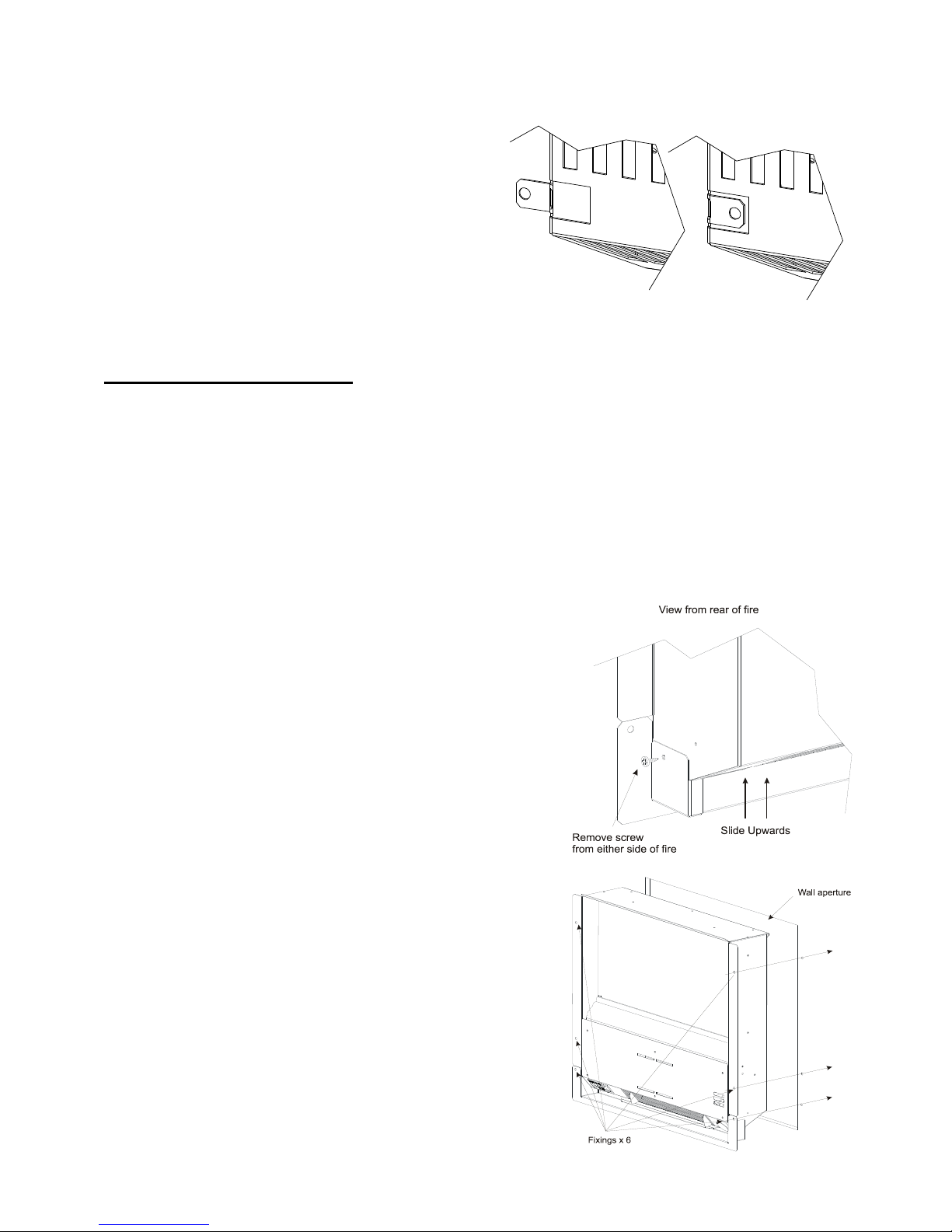
8. To fix the fire permanently to the wall there
is a tab at the rear of the fire on the bottom
right hand side (viewed from the front)
shown in the diagram right that should be
used. The tab should be unfolded out as
shown in the diagram right and then used to
insert the fixing the same as those used for
the wall hanger bar.
9. The Fascia may now be fixed to the fire
chassis – see fitting the facia.
FULLY INSET FITTING:
To inset the fire an aperture must be cut into the wall of 450 wide by 530mm high.
NOTE: The wall aperture must be at least 110mm deep to ensure that the fire fits
completely into the wall. NOTE: If a wall socket is fitted below or to the rear of the fire
allow sufficient gap between the wall socket and the fire to ensure that the fire fits
completely into the aperture.
If mounting into a brick or plaster wall ensure that the aperture is clean and free from dust.
Provision for a mains connection should be made at the bottom or the rear of the aperture
– If the appliance is to be hard wired allow sufficient length of mains cable to enable
removal of the appliance from the aperture with the
cable attached.
If the inset tray is not already fitted to the fire:
1. Remove two screws one from each side of the fire
back Fig 3
2. Slide the base tray onto the fire back until the base
tray touches the base of the fire, then fix with the
two screws removed in the previous step.
Then continue as follows:
1. Fix the mains cable to the underside of the
appliance. Fig2
2. Slide the fire into the aperture Fig 4
3. Check to ensure that the appliance is level.
4. Mark through the fixing holes in the outer flange
and then remove the fire from the wall aperture.
5. Drill the wall with a suitable sized drill and where
necessary insert raw plugs.
6. Connect the appliance to the mains socket.
7. Slide the complete fire into the aperture.
8. Fix the fire to the pre drilled holes with suitable
fixings.
9. Fit the Facia
Fig 3
Fig 4
5
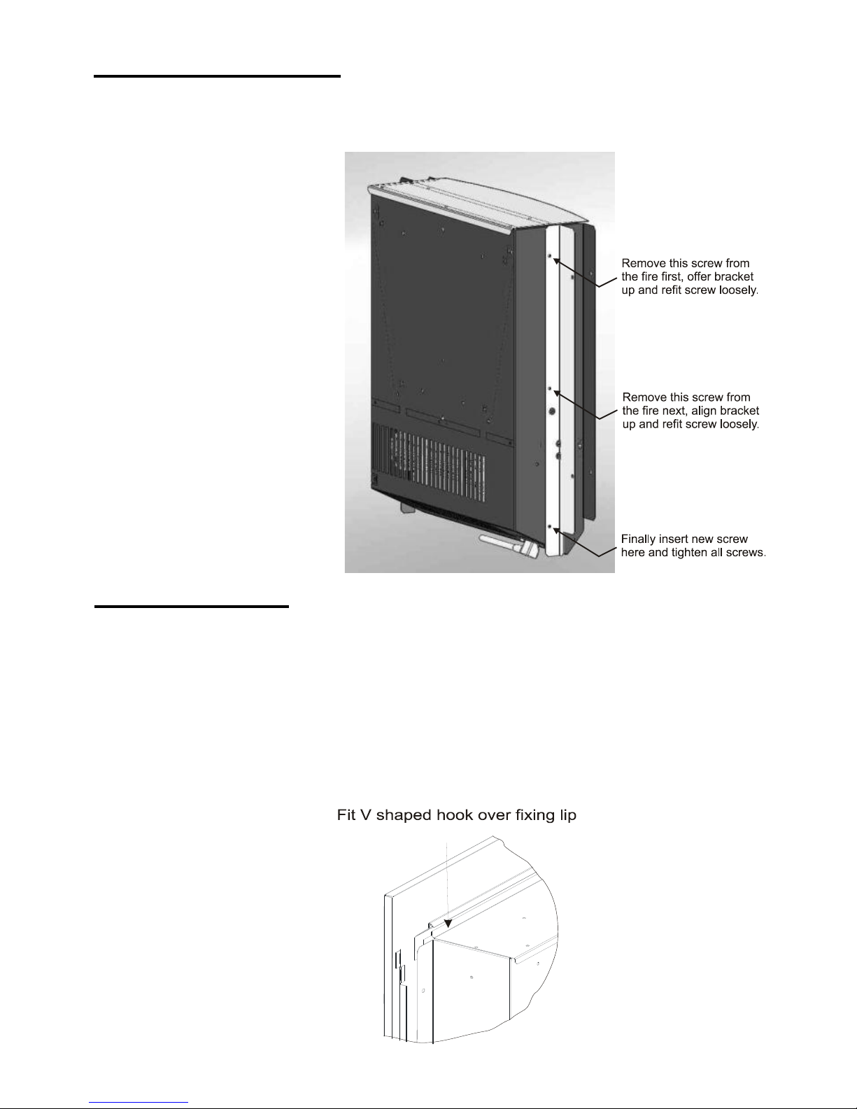
FITTING THE FACIA
The Fascia may now be fitted to the fire chassis as follows.
1. At the rear of the facia frame there is a large v shaped hook. Hook this over the
fixing lip located on the fire back. Fig 5
2. Carefully lower the bottom edge of the facia frame towards the fire back until the
magnets connect the facia frame to the fire back.
For Curvascape II models care should be taken when fitting the facia so as not to
damage the chrome trim or the fire fuel bed.
For Flamescape II models the glass panel fits to the fire in the same way as the
Curvascape II.
Fig 5
PARTIAL INSET FITTING:
To inset the fire an aperture must be cut into the wall of 450 wide by 510mm high.
OTHER DETAILS AS FOR “FULLY INSET FITTING” EXCEPT:
Ignore items 1 & 2 and follow
instructions as shown in
diagram right. Continue from
Item 1 “Then continue as
follows”.
6
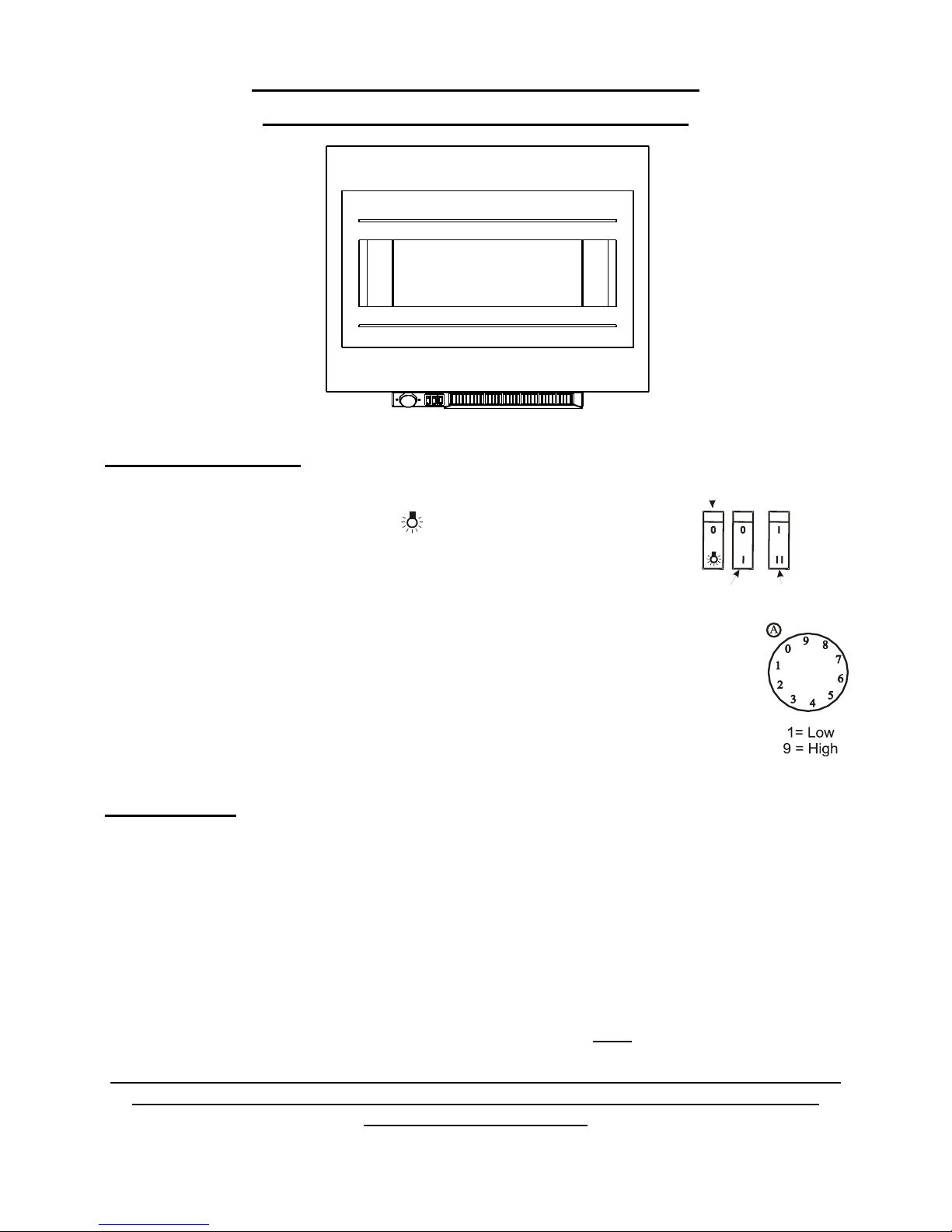
SECTION 2: ELECTRIC FIRE OPERATION
CURVASCAPE II AND FLAMESCAPE II MANUAL
Manual operation:
The three switches control the following:
Left hand switch - light effect only- ( = ON; 0 = OFF)
Middle switch -1kW Heat setting ( I = ON 1kW; 0 = OFF)
Right hand switch - 2 kW Heat Setting. (I = ON 1kW; II = ON 2kW)
Round Control – Thermostat - Note numbers do not represent temperature in
degrees.
Adjustment position indicated with marker - item A
The flame effect can be used without heat (if the thermostat is set to 0 then
there will be no heat output regardless of switch settings).
Thermostat:
The thermostat enables the room temperature to be controlled around a pre-set level and
can be used when the either of the two heat switches are depressed. To set the thermostat, first set the control fully clockwise to position 9 then turn on the heating elements and
heat the room to the desired temperature. When this temperature has been reached re-
duce the setting by turning the control anti-clockwise towards a lower figure until you hear
the thermostat click off and the heat from the fan cease. When the room temperature
drops the thermostat will turn the full heat from the fire back on again.
The thermostat control is designed to operate at room temperatures of 00C – 40
0
C.
At very low temperatures (approx. 6° C) the thermostat will NOT turn the fire off.
THE MAIN HEAT OUTLET IS BELOW THE FIRE FRONT. DO NOT TOUCH OR PLACE
ANY MATERIAL IN THIS AREA WHEN THE FIRE HAS RECENTLY BEEN IN USE
OR WHILST TURNED ON.
ON - OFF
Light Only
1 Heat Setting
st
2 Heat Setting
nd
 Loading...