

Page 1

Imperial
Cal. Products, Inc.
Installation Guide
And Users Manual
MODELS:
TG5000PS-SS – Island Hood
&
TW5000PS-SS – Wall Hood
425 Apollo St.
Brea, CA 92821
www.imperialhoods.com
800-851-4192
DO NOT THROW AWAY
PROPERTY OFTHE HOME OWNER
Page 2

Table of Contents
A. Important Safety Instructions …………………………….. P.01
- Installation ………………………………………………... P.01
- Operations …………………………………………….….. P.01
- Cleaning …………………………………………………... P.01
B. Before You Start ……………………………………………. P.02
C. Electrical requirements ……………………………………. P.03
D. List of Materials …………………………………………….. P.04
E. Planning for the instruction ………………………………... P.05
- Important ………………………………………………... P.05
- Venting Method ………………………………………… P.05
F. Installation Instructions ……………………………………. P.07
- For Island Type of Models……………………….………. P.07
- For Wall-Mount Type of Models ………………..………. P.09
G. Range hood operation……………………………………... P.10
H. Specification …………………………..,……………….........P.10
I. Trouble Shooting…………………….. ………………... P.11
J. Maintenance……………………….. ………………………. P.12
K. Wiring Diagram…………………………………………… P.13
READ AND SAVE THESE INSTRUCTIONS
SAVE THIS GUIDE FOR THE LOCAL ELECTRICAL INSPECTOR’S USE
APPROVED FOR RESIDENTIAL APPLIANCES
FOR RESIDENTIAL USE ONLY
* INSTALLATION MUST COMPLY WITH ALL LOCAL CODES
* Requirement 120V AC, 60Hz. 15 or 20 A Branch Circuit
* Must read the entire instructions before proceeding.
* Turn off power circuit at service panel and lock out panel, before wiring this appliance
INSTALLER: Must leave these instructions with this unit for the owner.
HOMEOWNER: Please retain these instructions for future reference and for local electrical inspectors’
use.
Page 3
A. IMPORTANT SAFETY INSTRUCTIONS
Read all Instructions before installing and operating this appliance.
Installation
Do not install if the outside/appearance of this appliance is already damaged.
1. The installation in this manual is intended for qualified installers, service technicians or someone with similar
qualified background NEVER attempt to install this appliance yourself.
2. Injury could result from installing the unit due to lack of appropriate electrical and technical background.
3. All electrical wiring must be properly installed, insulated and grounded. Old duct work should be cleaned or
replaced if necessary to avoid the possibility of a grease fire. Check all joints on duct work to insure proper
connection and all joints should be properly taped.
4. Personal Injury Hazard – Because of the weight and size of the rang hood, three or more people are needed to
move and safely install the range hood. Failure to properly lift range hood could result in damage to the product
or person.
5. SERVERE INJURY – Range hood may have sharp edges. Please wear protective gloves if it is necessary to
remove any parts for installing, cleaning or servicing.
Operations
1. Read all instructions in this manual before operating the appliance. Save these instructions for future reference.
2. Always leave safety grills and filters in place. Without these components, operating blowers could catch
on the hair, and loose clothing.
3. NEVER dispose cigarette ashes, ignitable substances, or any foreign objects into blowers.
4. NEVER leave cooking unattended. When frying, oil in the pan can easily overheat and catch fire. The risk of self
combustion is higher when the oil has been used several times.
5. NEVER cook on “open” flames under the range hood. Check deep-fryers during use: extremely hot oil may be
flammable.
Cleaning
DO NOT OPERATE BLOWERS WHEN FILTERS ARE REMOVED.
1. The saturation of greasy residue in the blower and filters may cause increased inflammability. Keep this
appliance clean and free of grease and residue build-up at all times to prevent possible fires.
2. Filters must be cleaned periodically and free from accumulation of cooking residue (see cleaning instructions
inside). Old and worn filters must be replaced immediately.
3. NEVER
disassemble parts to clean without proper instructions. Call our service center for removal instructions.
The manufacturer and distributors decline all responsibility in the event of failure to observe the instructions
given here for installation, maintenance and suitable use of the product.
The manufacturer and distributors further decline all responsibility for injury due to negligence and the
warranty of the unit automatically expires due to improper maintenance.
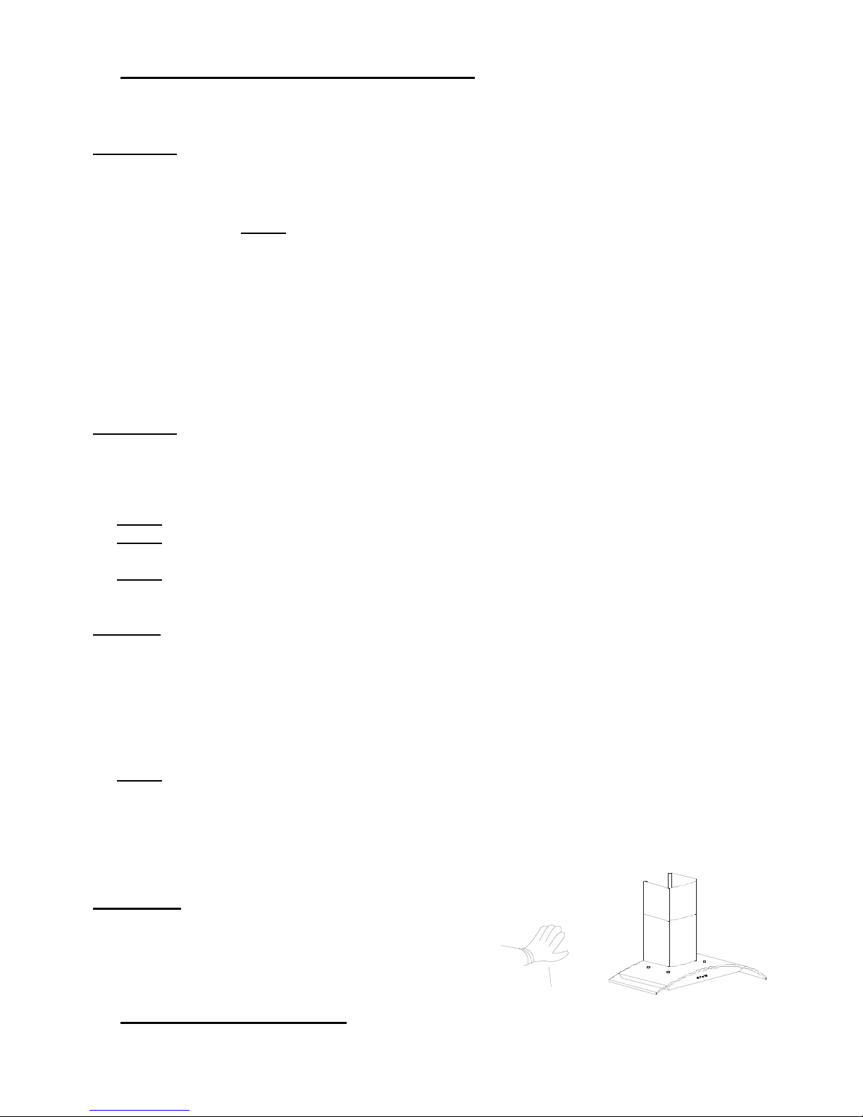
Safety Workman Gloves
Safety Note
Please wear “Safety Workman Gloves” for installation,
Cleaning, light bulb changing, and dismantling to
reduce the risk of any bodily injuries.
B. BEFORE YOU ST ART….
Page 4

It is very important for your safety and safety of others. Always read and obey all safety messages. All safety messages will inform you on
what the potential hazards are, how to reduce the chance of injury, and what can happen if the instructions are not followed.
These alerts are here to help you avoid potential hazards that can kill or hurt you. All
safety messages will follow the safety alert symbol and the word “WARNING”.
WAR NIN G
WARNING: TO REDUCE THE RISK OF FIRE, ELECTRIC SHOCK, OR INJURY TO PERSON OBSERVE THE FOLLOWING CAREFULLY :
1) Use this unit only in the manner intended by the manufacture. If you have any questions, please contact the distributor, importer, or
the manufacturer.
2) Before servicing or cleaning unit, switch power off at service panel and lock. When the service disconnecting means cannot be
locked, securely fasten a prominent warning device, such as a tag, to the service panel.
3) Installation work and electrical wiring must be done by qualified person(s) in accordance with all applicable codes and standards,
including fire-related construction.
4) Sufficient air is needed for proper combustion and exhausting of gases through the flue (Duct cover) of fuel burning equipment to
prevent back drafting. Follow the heating equipment manufacturer’s guideline and safety standards such as those published by the
National Fire Protection Association (NFPA), the American Society or Heating, Refrigeration and Air Conditioning Engineers
(ASHRAE), and the local code authorities.
5) When cutting or drilling into the wall or ceiling, do not damage electrical wiring and hidden utilities.
6) Dusted fans must always be vented to the outdoors.
WARNING: T O REDUCE THE RISK OF FIRE, USE ONLY METAL DUCT WORK.
CAUTION: FOR GENERAL VENTILA TING USE ONL Y. DO NOT
USE THE EXHAUST OVER HAZRDOUS OR EXPLOSIVE MATERIALS OR
VAPORS.
WARNING: TO REDUCE THE RISK OF INJURY TO PERSONS IN THE EVENT OF A RANGE TOP GREASE FIRE, OBSERVE THE
FOLLOWING: (Based in “Kitchen Fire safety Tips” published by NFPA)
1) SMOTHER FLAMES with a close-fitting lid, cookie sheet, or metal tray, then turn off the burner. BE CAREFUL TO PREVENT
BURNS. If the flames do not go out immediately, EVACUATE AND CALL THE FIRE DEPARTMENT.
2) NEVER PICK UP A FLAMING PAN – you may be burned.
3) DO NOT USE WATER, including wet dishcloths or towels – a violent steam explosion will result.
4) Use an extinguisher ONLY if: a) You know you have a class ABE extinguisher, and you already know how to operate it.
b) The fire is small and contained in the area where it started.
c) The fire department is being called.
d) You can fight the fire with your back to an exit.
CAUTION: TO REDUCE RISK OF FIRE AND TO PROPERLY EXHAUST AIR, BE SURE TO DUCT AIR GOES TO THE OUTSIDE –
DO NOT VENT EXHAUST AIR INTO SPACES WITHIN WALLS, CEILINGS, ATTICS, CRAWL SPACES, OR GARAGES.
WARNING: TO REDUCE THE RISK OF FIRE OR ELECTRIC SHOCK, DO NOT USE THIS HOOD WITH ANY EXTERNAL SOLID
STATE SPEED CONTROL DEVICE.
WARNING: TO REDUCE THE RISK OF A RANGE TOP GREASE FIRE
1) Never leave surface units unattended at high setting. Boil over cause smoking spillovers that may ignite. Heat oils slowly on low or
medium settings.
2) Always turn hood on when cooking at high heat or when cooking flambing foods. (i.e. Crepes Suzetter, Charries Jubilee, Peppercorn Beef Flamb).
3) Clean ventilating fans frequently. Grease should not be allowed to accumulate on fan or filter.
4) Use proper pan size. Always use cookware appropriate for the size of the surface element.
WARNING: T O REDUCE THE RISK OF FIRE, ELECTRIC SHOCK, OR INJURY TO PERSONS, OBSERVE THE FOLLOWING:
1) Use this unit only in the manner intended by the manufacture. If you have any questions, contact the manufacturer.
2) Before servicing or cleaning unit, switch the power off at service panel and lock switch power off at service panel to prevent power
from being switched on accidentally.
3) When the service disconnecting means cannot blocked, securely fasten prominent warning device such as a tag to service panel.
WARNING: TO REDUCE THE RISK OF A RANGE HTOP GREASE FIRE:
1) Never leave surface units unattended at high setting.
2) Boil overs cause smoking and greasy spillovers that may ignite.
3) Slowly heat oils on low or medium setting
4) Always turn hood ON when cooking at high heat or when cooking flaming foods.
5) Clean ventilating fans frequently.
Page 5
C. ELECTRICAL REQUIREMENTS
OBSERVE ALL GOVERNING CODES AND ORDINANCES
WARNING
* Electrical ground is required on this range hood.
* Check with a qualified electrician if you are not sure whether the range hood is properly grounded.
* Failure to follow electrical requirements may result in a fire.
* a fuse in the neutral or grounding circuit could result in electrical shock.
* If water pipe is interrupted by plastic nonmetallic gaskets or other materials, DO NOT use for grounding.
** DO NOT have a fuse in the neutral or grounding circuit.
** DO NOT ground to a gas pipe
IMPORTANT:
It is customer’s responsibility to contact a qualified electrical installer and assure that the electrical installation is adequate and in
conformance with National Electrical Code, or CSA standards and all local codes and ordinances.
A. Save installation instructions for electrical inspector’s use.
B. If codes permit and a separate ground wire is used, it is recommended that a qualified electrician determines that if the ground path is adequate.
C. Please remove the house fuse or open circuit before any installation for personal safety. DO NOT use extension cord or adapter plug
with this appliance.
D. RISK OF ELECTRICAL SHOCK – This range hood must be properly grounded.
E. The range hood must be connected with copper wire only.
F. The range hood should be connected directly to the fused disconnect (or circuit breaker) box through flexible, armored or nonmetallic
sheathed copper cable. Allow some slack in the cable so the appliance can be moved if servicing is ever necessary.
G. A UL or C.S.A. listed conduit connector mush be provided at each end of the power supply cable (at the range hood and at the junction box).
H. When making the electrical connection, cut a 1-1/4” hole in the wall. A hole cut through wood must be sanded until smooth a hole
through metal must have a grommet.
I. When cutting or drilling into wall or ceiling, do not damage electrical wiring and other hidden utilities.
J. Wire sizes must conform to the requirements of the National Electrical Code ANSI/NFPA 70- latest edition*, or CSA Standards C22.1-04,
Canadian Electrical Code Part 1 and C22.2 No. 0-M91 – latest edition** and all local codes and ordinances.
K. Connect three wires according to color (Black to Black, White to White, and Green to Green) to house wires and cap with wire connectors.
Black
White
Gre en
BLACK TO BLACK (Hot)
WHITE TO WHITE (Neutral)
GREEN TO GREEN (Ground)
D. LIST OF MATERIALS
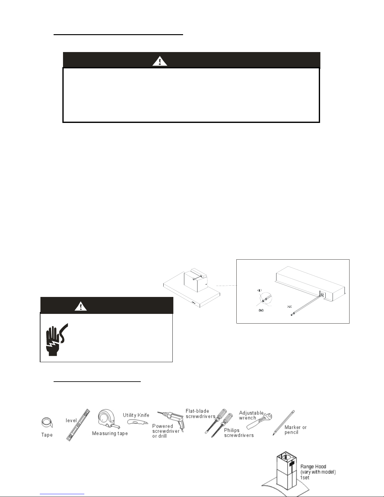
TOOLS FOR INSTALLATION:
PARTS SUPPLIED (Island type Model)
* National Fire Protection Association Batterymarch Park
Quincy, Massachusetts 02268
** CSA International 8501 East Pleasant Valley Road Cleveland
Ohio 44131-5575
HAZARD OF ELECTRICAL SHOCK!
Do not perform service on an electrically live system.
Disconnect the main electrical supply before servicing
this device. Touching electrical connectors or other
exposed electrical circuitry inside this range hood when
they are energized could result in death, serious bodily
injury, or property damage.
WARNI NG
Page 6

Descripti
on Quality
Main body (Body of Hood) include aluminum filter (s) 1 Set
Duct Cover Sets (Upper Duct & Lower Duct) 1 Set
Supporting frames (with 8 sets of 5mm x 16mm screw with washers) 1 Set
Duct Set (include O-ring) 1 Set
Installation Guide 1 Set
Φ5mm x 16mm Screw with Flat Washer
8 Sets
Φ4mm x 16mm Screw with Washers
8 Sets
Φ4mm x 16mm Screw
6 Pcs
Φ4mm x 25mm Socket Head Cap Screw and Washer
2 Sets
Screws Box
Hexagonal Wood Screws 4 Sets
Screws Box
PARTS SUPPLIED (Wall-Mount Type Model)
Description Quality
Main body (Body of Hood) include aluminum filter (s) 1 Set
Upper Duct Cover and Lower Duct Cover 1 Set
Duct Set (include O-ring) 1 Set
Installation Guide 1 Set
Φ5mm x 16mm Screw with Flat Washer
4 Sets
Φ4mm x 16mm Screw
6 Sets
Φ4mm x 8mm Tapping Screw
4 Pcs
Toggle Bolts ( #3/16" x 3") 4 Sets
Body Hook 2 Sets
Screws Box
Duct Cover's Fix Panel 1 Pc
Screws Box
NOTICE: 1. Remove the range hood from the carton packaging and place on a flat surface for assembly.
2. Check carefully to make sure that no mounting hardware or parts are missing.
3. DO NOT REMOVE THE PLASTIC COVERING ON THE DUCT COVERS AT THIS TIME.
As it protects the duct covers from scratches during installation.
E. PLANNING FOR THE INSTALLATION
WARNI N G
* Proper installation is your responsibility – Must have a qualified technician install this range hood.
* Read the entire installation guide and users manual thoroughly, and understand instructions and warnings.
* PERSONAL INJURY HAZARD – Because of the weight and size of the range hood, three or more people
are needed to move and safely install the range hood. Failure to properly lift range hood could result in
damage to the product or person injury.
* All opening in ceiling and wall where range hood will be installed must be sealed.
* Range hood location should be away from strong draft areas (windows, doors and strong heating vents).
* SEVERE INJURY – Rotating fan can cause severe injury. Stay clear of fan when motor is running.
* SEVERE INJURY – Range hood may have very sharp edges. Please wear protective gloves if it is
necessary to remove any parts fro installing, cleaning or servicing.
Page 7

A. Important: Must measure following steps before installation.
The Duct Covers are adjustable and designed
to meet various ceiling or wall height. The duct
covers can be adjusted for ceiling between 8ft
and 9ft depending on the distance between the
bottom of the hood and the cook top) For
shorter ceiling, have the duct cover cut at a
sheet metal shop. For higher ceilings buy an
extra upper duct cover which would replace the
original one that came with the hood.
1) Distance from the floor to the ceiling.
2) Distance between the floor to the counter
top/stove.
3) Distance between the counter/stove and
range hood (recommended 28” to 32”).
4) Height of range hood and duct covers
5) Height of the range hood installation.
B. Venting Methods
This range hood can be installed as either ducted or ductless.
WARNING: BEFORE MAKING ANY CUTS OR HOLES FOR INSTALLATION, DETERMINE WHICH
VENTING METHOD WILL BE USED AND CAREFULLY CALCULATE ALL MEASUREMENTS
(a). Outdoor Venting methods (for outdoor venting through the roof or wall only)
The hood is equipped with a transition "duct set" for discharge of fumes to the outdoor. Vent work can terminate
either through the roof or wall. To vent through a wall, a 90 degree elbow is needed.
IMPORTANT:
- Vent system must vent to the outside (through roof or side wall), unless using a ductless re-circulating kit.
- Do not terminate the vent system in an attic or any other enclosed area.
- Recommended to use metal / flexible aluminum vent only.
- Never use plastic vent.
- Always Keep the duct clean to ensure the proper airflow.
- NEVER exhaust air or terminate duct work into spaces between walls, crawl spaces, ceiling, attics or
garages. All exhaust must be ducted to the outside.
- Use caulking to seal exterior wall or roof opening around the cap.
- Do not use 4" (10.2cm) laundry-type wall caps.
- Always keep the duct clean to ensure proper airflow.
- It is recommended that the range hood be vented vertically through the roof through 7" round
metal/aluminum vent work. The size of the vent should be uniform.
- Use no more than three 90 degree elbows and do not install two elbows together.
- Make sure there is a minimum of 24"(61cm) of straight vent between the elbows if more than one elbow is
used. The length of vent system and number of elbows should be kept to a minimum to provide efficient
performance.
Page 8

- The vent system must have a damper. If roof or wall cap has a damper, Do Not use damper supplied with
the range hood.
- Use duct tape to seal all joints in the vent system.
- Fasten all connections with sheet metal screws and tape all joints with certified Silver Tape or Duct Tape.
Calculate the duct run length:
If ducted with the required minimum of 7" round duct work, the duct run should not exceed 35 equivalent feet.
Calculate the length of the duct work by adding the equivalent feet as below for each piece of duct in the system.
1. Use no more than three 90 degree Elbows.
2. Make sure that there is a minimum of 24" of straight
duct between elbows if more then one is used.
3. DO NOT install two elbows together.
4. If you must elbow right away, do it as far away from the hood's exhaust opening as possible.
45 Elbow - 3.0 f eet
90 Elbow - 5.0 fee t
90 Flat Elbow - 12.0 fe et
Wall Cap - 0. 0 feet
o
o
o
9 Feet Straight Du ct 9. 0 feet
2-90 E lb ow 10. 0 fee t
Wall Ca p 0 .0 fe et
Total Syste m 19 .0 fe et
o
(b). Ductless Re-circulating Kit (Charcoal Filter)
- Ductless conversion is intended for applications where an exhaust duct work is not possible to be installed. When
converted, the hood functions as a purifying hood rather than an exhaust hood. Fumes and exhaust from
cooking is drawn and filtered by a set of charcoal filters. The air is then purified and re-circulated back within the
home.
- Ductless conversion is a "purifying" unit, a set of charcoal filter and an air deflector are required in addition to it
standard aluminum filter set.
- The aluminum filter are intend to capture residue from cooking, the optional charcoal filter helps to purify fumes
exhausted from cooking, and the optional air deflector redirects filter clean air back to the house.
F. INSTALLATION INSTRUCTIONS
- Before making cutouts, make sure there is proper clearance within the ceiling or wall for exhaust vent.
- Check your ceiling height and the hood height maximum before you select and install your hood. The hood installation height
above cook top is users’ preference. The lower the hood above the cook top the more efficient the capturing of cooking odors,
grease and smoke. The hood shall be installed at 28" minimum to 32" above the countertop.
- Fitting material is provided to secure the hood to most types of ceilings or walls. However, a qualified technician must verify
suitability of the materials in accordance with the type of wall. Must consult a qualified installer and check if the screws and
drywall anchor fit perfectly with your wall.
Page 9

- Due to the size and weight of this range hood, the support must be firmly attached to the ceiling or wall. For plaster or sheet
rock ceilings, the support must be attached to the joists. If this is not possible, a support structure must be built behind the
plaster or sheet rock. The manufacturer assumes no responsibility for injury or damage caused by improper installations.
- Put a thick, protective covering over counter top, cook top or range to protect from damage or dirt. Remove any hazardous
objects around the area when installing.
WARNING: CHECK YOUR CEILING OR WALL COMPOSITION TO USE APPROPRIATE ANCHORS.
(1) FOR ISLAND TYPE OF MODELS:
INSTALLATION: SUPPORTING FRAMES
1. Drill four holes on the false ceiling (figure 1). Fasten two hexagonal wood screws into two of these holes opposite from each
other and reserve approximately 1/4" for the top support plate as shown in (figure. 2). For outdoor ducting method, cut out a
circle of 7-1/2" diameter for duct work.
2. Screw down the screws on the supporting frames then pull down the frames to adjust it to the length required then place outer
support frames onto the inner supporting frame (with top plate). Lock the support frames using sixteen 4 mm x 16 mm Phillips
head screws (figure 3).
3. Align the holes on top support plate with two screws on the ceiling. Push upward (1) and slide forward (2) so the top
supporting plate locks into place, (see figure 4). Fasten existing two hexagonal wood screws, insert two more on the last two
holes and fasten them. Make sure the supporting frame fixture is secure before releasing!
4. Install the duct set using six Φ4mm x 16mm screw (See figure 5).
INST
ALLATION: DUCT COVERS
5. Remove the plastic covering on the duct covers at this time. Be careful, there may be sharp edges on the duct cover.
Please wear protective gloves while installing the duct cover to prevent personal injury and prevents scratches on the cover
during installation.
6. Slide in both duct covers and screw the upper duct cover tightly by 2 sets of 4mm x 25mm socket head cap screws
Page 10

and washers. Pay extra attention to sharp edges on the duct covers and minimize duct cover movements to avoid
scratches on the duct covers. You may use a screw driver to prevent them from sliding down as illustrated in figure 6.
CAUTIO
N:
1. PAY EXTRA ATTENTION
TO SHARP EDGES ON THE
DUCT COVER AND MINIMIZE
DUCT COVERS MOVEMENTS
TO AVOID SCRATCHES ON
THE COVER!
2. MAKE SURE THE SCREW
DRIVER CAN WITHSTAND
THE WEIGHT!
INSTALLATION: HOOD BODY
WARNING: EXCESSIVE WEIGHT THREE OR MORE PEOPLE ARE NECESSARY.
CAUTION: MAKE SURE THE RANGE HOOD IS SECURE BEFORE RELEASING.
7. Install the hood body onto the supporting frame and secure it with eight 4mm x 16mm screws and washers (figure 8).
INSTALLATION: ALUMINUM TUBE
8. Install the aluminum duct on to the body of the hood and connect the duct to the exterior exhaust system after install the
hood body onto the supporting frame. Make sure all joints are secure and air tight. Use certified Silver Tape or Duct Tape
to make all joints secure and air tight. Figure 9.
9. Take down the screw driver and slide the lower duct cover into position slowly. Figure 10.
----- Then complete installation -----
(2) FOR WALL-MOUNT TYPE OF MODELS:
1. Locate an optimal location to place the range hood. Mark the leveling points for two Body Hooks (figure. 1) on the wall and
drill two holes insert two toggle bolts and reserve approximately 1/4" for the body hooks. Be sure to use appropriate anchors
for your wall.
Page 11

2. Use four sets of 5mm x 16mm screws with flat washer to install the body hooks onto the hood (see figure 2)
3. Install the duct set by using six 4mm x 16mm screw (See figure 3).
4. Find an optimal location for the duct cover's fix panel. The fix panel must be placed directly above and align with the two
body hooks. Drill two more holes insert two toggle bolts. Secure the fix panel with 2 toggle bolts and screw tightly. Be sure
to use appropriate anchors for your wall. (Figure 4)
5. Then hang the hood on the wall and tighten the screws as figure 4 shown.
CAUTION: MAKE SURE THE RANGE HOOD IS SECURE BEFORE RELEASING!
6. Install the aluminum duct on to the body of the hood and connect the duct to the exterior exhaust system. Make sure all
joints are secure and air tight. Use certified Silver Tape or Duct Tape to make all joints secure and air tight (figure 5).
7. Remove the plastic covering on the duct covers at this time. Be very careful, there may be sharp edges on the duct cover.
Please wear work protective gloves while installing
the duct cover to prevent personal injury and prevents scratch on the cover
during installation.
8. Place upper duct cover and lower duct cover over the body of the hood as shown in figure 6. Upper duct cover is the one that
contains holes on both side. Slide up the upper duct cover towards the duct cover's fix panel. Use two of 4mm x 8mm
tapping screws to secure the upper duct cover onto the panel. Finally secure the lower duct cover to the hood body by using
of 4mm x 8mm tapping screws.
Page 12

G. RANGE HOOD OPERATIONS
Lig ht Sw itch
Po we r Switc h
Low Speed
Medium Speed High Speed
TURN ON:
- Press the speed control (Low Speed, Medium Speed, High Speed) switch to select the desired level of
power.
Once button is pressed, the previous speed mode will be cancel.
- Press Light Switch to turn on the lights.
TURN OFF:
- Press the Power Switch to turn off the power.
- Press Light Switch to turn off the lights.
H. SPECIFICATIONS
Model Island Type of Range Hood Wall-Mount Type of Range Hood
Power Rating 120V / 60Hz ( USA & Canada standard )
General Input Power 164W ( 160W + 4 x 1W ) 162W (160W + 2 x 1W)
Motor Input Power 160W 160W
Motor Revolution 1400 R.P.M. (±10% ) 1400 R.P.M. (±10% )
Levels Of Speed Control 3 Levels 3 Levels
Air Pressure 280 Pa 280 Pa
Noise Level (dB/Sone) Approximately 55 / 2.8 to 59/ 3.8 (Lowest to highest Speed)
Motor Type Single motor Single motor
Fan Type Sirocco Sirocco
Control Type Push Button Push Button
Illumination 1W * 4 (LED Light) 1W * 4 (LED Light)
Venting Size 7" inch Round 7" inch Round
* Specifications subject to change without notice.
Page 13

I. TROUBLE SHOOTING
WARNI N G
HAZARD OF ELECTRICAL SHOCK!
Do not perform service on an electrically live systems. Disconnect
the main electrical supply before servicing this device. Touching
electrical connectors or other exposed electrical circuitry inside this
range hood when they are energized could result in death,
serious bodily injury, or property damage.
1. If the range hood does not operate after installation:
- Check if the range hood has been plugged in, make sure that all power has been turned back on and all
electrical wiring is properly connected.
- Check the power connection is connected properly.
- Make sure the wiring between the switch board and control board is connected properly.
2. The range hood vibrates when the blower is on:
- The range hood might not have been secured properly on to the wall.
- Check the motor to see if it is secured in place. If not, tighten the motor in place.
- Check to see if there is a damaged blower wheel; if so change the blower wheel.
3. The blowers seem weak:
- Check that the duct sized used is at least 7" or 3-1/4 x 10". Range hood WILL NOT function efficiently with
insufficient duct size.
- Check if duct is clogged or if damper unit is not opening properly. A tight mesh on a side wall cap unit might
also cause restriction to the air flow.
4. The lights work but the blower is not spinning at all, is stuck or is rattling:
- The blower might be jammed or scraping the bottom due to shipping damage.
- The motor is defective, possible seized - change the motor.
- The thermally protected system detects if the motor is too hot to operate and shuts the motor down. In this
case the motor will function properly after the thermally protected system cool down.
5. The hood is not venting out properly:
- Make sure the distance between the cook top and the bottom of the hood is between 28" and 32".
- Reduce the number of elbows and length of duct work. Check if all joints are properly connected, sealed,
and taped.
- Make sure the power is on high speed for heavy cooking
- Check weather the direction of duct opening is against the wind, if so then adjust the duct opening direction.
- Check to see if you are using correct duct sizes.
6. The light does not work:
- Check weather the light bulb is loose. If so then tighten the light bulb.
- Swap out light assembly to working ones to determine weather it is caused by defective light bulbs
NOTE: For all other inquiries, please contact us.
Page 14

J. MAINTENANCE
Prior to any maintenance operation ensure that the range hood is disconnected from the power supply.
WARNING : FAILURE TO CARRY OUT THE BASIC STANDARDS OF CLEANING THE R ANGE HOOD AND
REPLACEMENT OF THE FILTERS MAY CAUSE FIRE RISKS. THEREFORE WE RECOMMEND
OBSERVING THESE INSTRUCTIONS.
WARNI N G
BURNS HAZARD
Light bulb become extremely hot when turned on. DO NOT touch bulb until switched off and
cooled. Touching hot bulbs could cause serious burns.
SEVERE INJURY
Rotating fan can cause severe injury. Stay clear of fan when motor is running.
Range hood may have very sharp edges. Please wear protective gloves if it is necessary to
remove any parts for installing, cleaning or servicing.
Cleaning Exterior surfaces:
- The range hood should be cleaned regularly internally and externally.
- Clean periodically with hot soapy water and clean cotton cloth. Do not use corrosive/abrasive detergent (e.g. Comet
Power Scrub ®, EZ-off ® oven cleaner), or steel wool/scoring pads, which will scratch and damage the stainless steel
surface.
- For heavier soiled areas use a liquid degreaser such as "Formula 409® " or "Fantastic® " brand cleaners.
- After cleaning, you may use non abrasive stainless steel polish/cleaner such as 3M® or ZEP® , to polish and buff
out the stainless luster and grain. Always scrub lightly with clean cotton cloth, and with the grain.
Cleaning Aluminum Grease Filter / Stainless Steel Filter less Grill:
- The metal filters fitted by the factory are intended to filter out residue and grease from cooking. It need not be
replaced on a regular basis but should be kept clean.
- SUGGESTION: Filters should be cleaned once a month using non aggressive detergents, either by hand or in the
dish-washer. Dishwasher should be set to a low temperature and a short cycle.
- When washed in a dish washer, the grease filter may discolor slightly, but this does not affect its filtering capacity.
- Dry filters and re-install before using hood.
Page 15

Replacing the light bulb:
LED Light Design: - For LED Light replacement, please contact with distributor(s)/ dealer(s)
- Should the light bulb burned out due to age or prolonged use, replace with LED bulb.
- If new lights do not operate, make sure the light bulb is inserted correctly.
Before replacing LED light ensure the unit is switched off, when you want to change the LED light please always wear
working gloves.
WARNING: Disconnect the hood from electricity and be sure the lights are cool.
1. Turn off the range hood.
2. Make sure the lights are cool to touch, Use a flat hand screwdriver or equivalent tool carefully turn the inner ring
counter-clockwise with to pop out the protective covering of the light.
3. Using suitable tool (small screw driver) gently pry off the LED light set.
4. Taking off the wire connecter with LED light set.
5. Replace a new LED light set and reconnect the wire to the connecter.
6. Before push back to original LED light position, turn the switch on and test the LED light.
K. WIRING DIAGRAM
Bla ck
Capacitor
Black
Yell ow & Gre en
Coffee
Coffee
White
Black
Blue
Gray
Ye ll ow
Gray
Black
Bl u e
Ye ll o w
Red
Black
Green
Green
Yellow & Green
Red
Red
Black
LED
Light
Rectifier
White
White
Page 16

YOUR IMPERIAL WARRANTY
Proof of original purchase is needed to obtain service under warranty.
Warranty: One year, from the date of the original purchase, we will provide
In-home service for parts and labor. Parts ONLY for one additional year.
Call for service at: 800-851-4192.
Items Imperial Will NOT Pay For
1 Service calls to correct the installation of your appliance, to instruct you how to
use your appliance, to replace or repair house fuses or the correct housing
wiring or plumbing.
2 Service calls to repair or replace appliance light bulbs or filters.
3 Repairs when your appliance is used for other than normal, single family
household use.
4 Damage resulting from accident, alteration, misuse, abuse, fire, flood, acts of
God, improper installation, installation not in accordance with the electrical or
plumbing codes.
5 Replacement parts or repair costs for units operated outside the United States.
6 Pickup and delivery. This appliance is designed to be repaired in the home.
7 Repairs to parts or systems resulting from unauthorized modification made to
the appliance.
8 Expenses for travel and transportation for product service in remote locations.
9 The removal and reinstallation of your appliance if it is installed in an
inaccessible location or is not installed in accordance with the published
installation instructions.
10 Replacement parts or repair labor costs when the appliance is used in a
country other than the country in which it was purchased.
 Loading...