

Page 1
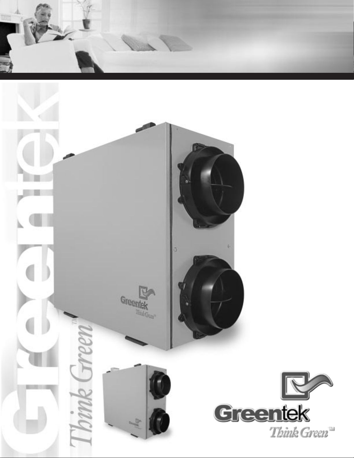
STATIC AND STATIC WITH MOTORIZED DAMPERS MODELS
INSTALLATION
GUIDE
Horizontal
series
• MODEL SH
TM
• MODEL SHM
TM
• MODEL SHM
TM
• MODEL SH
TM
Page 2
About Us
Imperial Air Technologies Inc. is the only manufacturer that offers you a complete range of products
designed to improve indoor air quality, and that provides a wide selection of accessories to facilitate
installation.
Our vision – To offer a complete range of GreentekTMproducts that satisfy environmental concerns.
Whether your needs involve ventilation, purification, humidification or filtration, Greentek
TM
has the
customized solution for you, with its range of quality products backed by the best warranty in the
industry.
Installation
1. Ventilation Needs
2. Typical Installation
3. GreentekTMHRV Systems
4. Finding a Suitable Installation Area for the HRV
5. Installation of the HRV
6. Rigid Duct
7. Insulated Flex
8. Motorized Damper Assembly (Model SHM only)
9. Condensation Drain Line
10. Outside Hoods
11. Balancing Damper
Functions and Controls
12. Control (Model SHM only)
13. Troubleshooting
Technical Information
14. Maintenance
15. Accessories
16. Wiring Diagram (Model SHM only)
17. Specification and Technical Information
PAGE
2
Greentek
TM
Peace of Mind
Limited
WARRANTY
All GreentekTMproducts are backed by
the best limited warranty in the industry,
for your peace of mind.
You benefit from a lifetime warranty on
the core, and a 5 year warranty on all
other components. So you can breathe
easy.
Safety
Considerations
for HRV
1. Read entire manual before
attempting to install the unit.
2. Always determine how the operation
of the unit will interact with
Combustion Appliances (i.e. Gas
furnace, Wood stoves, Oil furnace…)
3. Never install a unit in situations where
normal operation, lack of operation or
partial failure may result in
backdrafting or improper functioning
of Combustion Appliances.
4. Keep the units’ Fresh air intake a safe
distance from any potential source of
contamination, which may cause
health problems.
Redefining Indoor Air Quality
Solutions worthy
of nature...
TM
3
3
5
5
6
6
7
8
9
10
11
12
12
13
13
14
15
INFORMATION FOR INSTALLERS PAGE
INFORMATION FOR HOME OWNERS AND INSTALLERS PAGE
INFORMATION FOR HOME OWNERS AND INSTALLERS PAGE
Page 3
PAGE
3
STATIC AND STATIC WITH MOTORIZED DAMPERS MODELS
Determine Your
Ventilation Needs
installation
How much fresh air do I need? Good air
quality is based in part on the capacity of
the home’s ventilation system.
Usually, the HRV’s capacity is measured in
CFM (Cubic Feet per Minutes) or L/s
(Liters per Seconds) of fresh air being
distributed in the living space. The Room
Count Calculation or the Air Change per
Hour Method shows you how to
determine your ventilation needs.
Air Volume
Needed
installation
In a typical installation there must be an
adequate air volume passing through the
unit in proportion of the pressure from
the heating system.
Exemple: On the warm side*, the air volume needed is based on a 26’ rigid duct.
On the cold side*, the proportional eqivalent is 18’ of rigid duct.
* Between the model SH and the
forced air system.
**Between the model SH and the
outside intake.
A. Room Count Calculation
B. Air Change per Hour Method
2. Typical Installation
1.Ventilation Needs
LIVING SPACE
Master Bedroom
With Basement
Without Basement
Single Bedroom
Living Room
Dinning Room
Family Room
Recreation Room
Other
Kitchen
Bathroom
Laundry Room
Utility Room
TOTAL cu ft X 0.3 per hr = total
Take total and divide by 60 to get CFM
Number of Rooms CFM (L/s) CFM Required
x 20 cfm (10 L/s) =
x 20 cfm (10 L/s) =
x 10 cfm (5 L/s) =
x 10 cfm (5 L/s) =
x 10 cfm (5 L/s) =
x 10 cfm (5 L/s) =
x 10 cfm (5 L/s) =
x 10 cfm (5 L/s) =
x 10 cfm (5 L/s) =
x 10 cfm (5 L/s) =
x 10 cfm (5 L/s) =
x 10 cfm (5 L/s) =
TOTAL ventilation requirement (add last column) =
25’ x 40’ house with basement
1,000 sq. ft. x 8’ high x 2
(1stfloor = basement)= 16,000 cu. ft.
16,000 sq. ft. x 0.3 ACH
= 4,800 cu. ft.
4,800 sq. ft. / 60 Minutes
= 80 CFM
1 CFM = 0.47189 L/s
1 L/s = 3.6 m3/hr
80 CFM
is your ventilation needs
Example:
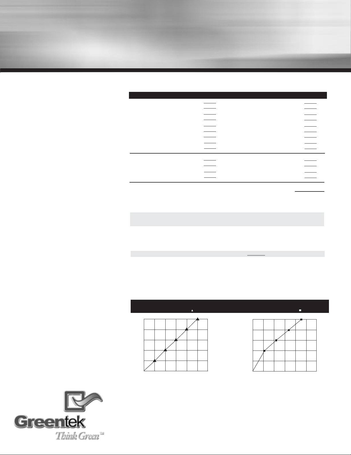
VENTILATION PERFORMANCE - MODEL SH
0.25
0.20
0.15
0.10
0.05
0.00
Supply
Return
60 70 80 90 100
Ft3/min. of HRV (Exhaust)
Supply
SUPPLY (“W.C.)
0.25
0.20
0.15
0.10
0.05
0.00
60 70 80 90 100
Ft3/min. of HRV (Fresh Air Intake)
Return
RETURN (“W.C.)
Page 4
Exhaust from the
supply and supply
in return
installation
Make sure that the Supply air from HRV is
at least 3 feet from the forced air system.
Can be different from a region to an
other. You should check with your local
code or the forced air system’s
manufacturer.
Airflow Direction
installation
Check the airflow direction before starting
the unit. If the airflow is not as indicated,
flip the core to the appropriate side.
Note: To install the core unit accordigly to
with the airflow, locate the four arrows on
the core decal and read the directions.
(Side A or side B)
PAGE
4
3. Typical Installation (continued)
Forced Air System
6’
18”
Heat
Recovery
Exhaust from supply and supply in return
FOR MINIMUM DISTANCE BETWEEN
RETURN AND FORCED AIR SYSTEM
Check with your local building codes and forced air system
manufacturer
3’
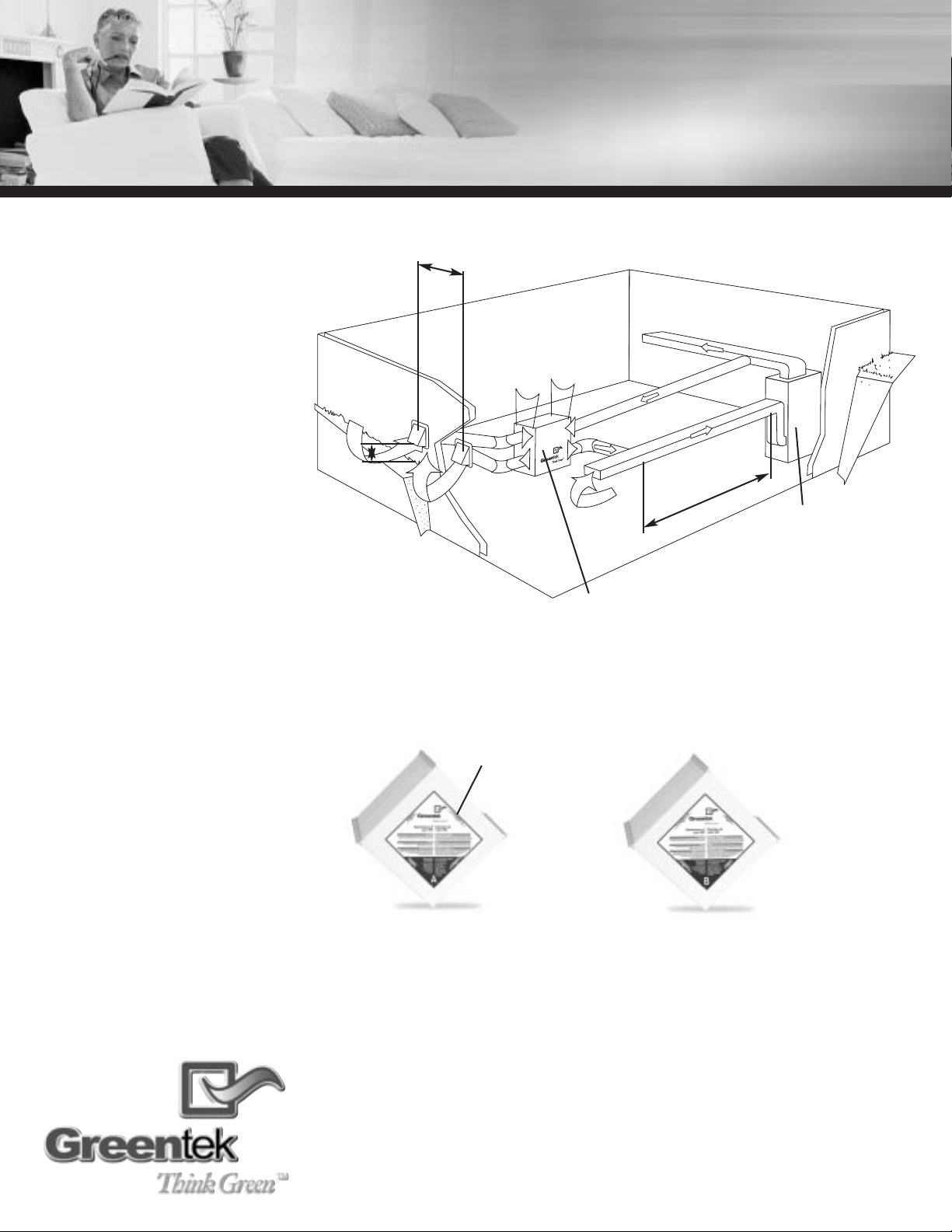
Figure 3.2 Core unit side A
Figure 3.3 Core unit side B
Read the arrows for
airflow direction
Page 5
PAGE
5
STATIC AND STATIC WITH MOTORIZED DAMPERS MODELS
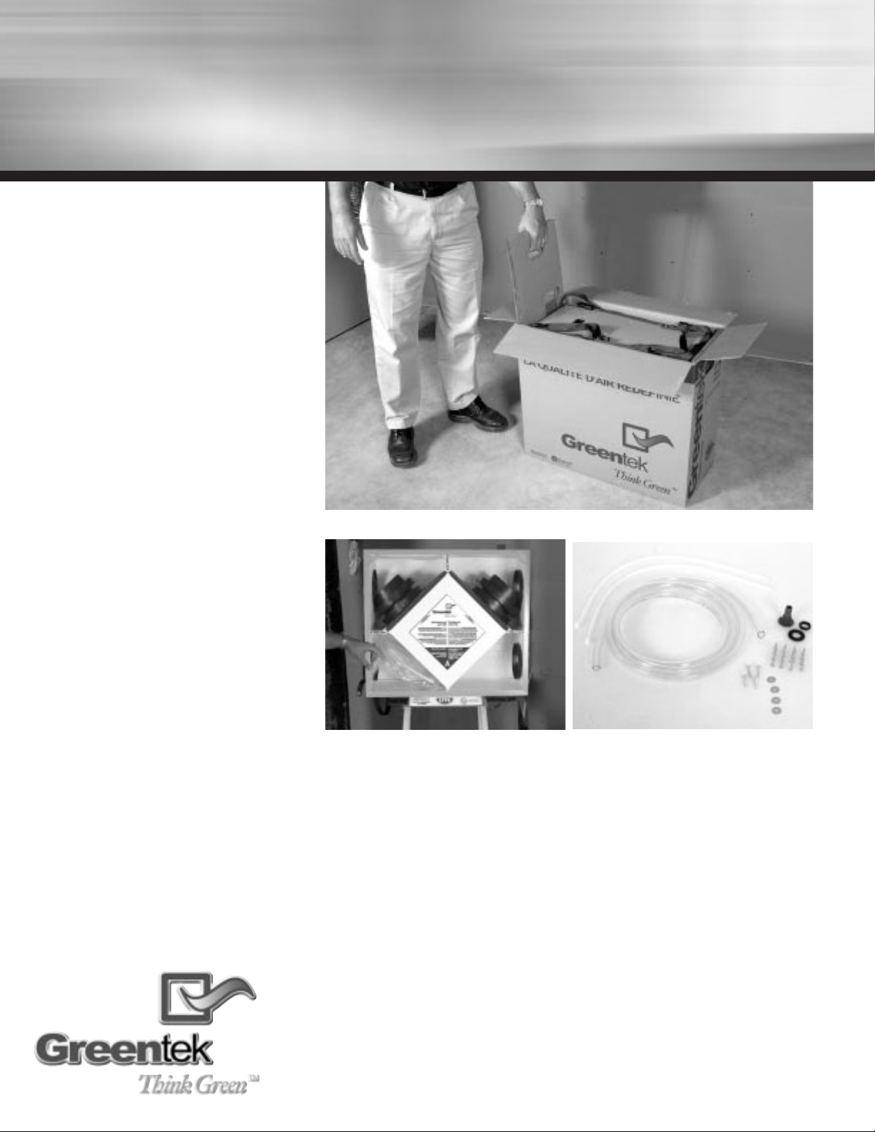
Installation Kit
Included in the installation kit:
• 4 Collars
• 1 Condensation Drain Line
• 1 Drain Adapter with Nut
• 2 Tie Wraps (30”)
• 16 screws (#10 x 5/8”)
• 4 screws (#10 x 1”)
Figure 3.1 Pull out the inserts first then use the straps to lift the unit out of the box
3. GreentekTMHRV Systems
4. Finding a suitable installation area for HRV.
Figure 3.2 Installation kit is shipped inside the unit
Figure 3.3 Installation kit
The HRV unit should be installed in a mechanical room or as close to an outside wall as possible.
This would assure a short run of insulated flexible duct.
The HRV unit must always be installed in an area where the air is tempered to avoid freezing of
the condensate line. The contractor should install the unit in area that is very accessible to allow
the homeowner easy access for maintenance.
You should have access to a condensate drain near the HRV to avoid the use of condensate pump.
Page 6

PAGE
6
figure 1.1
The SPM
TM
system is
supplied with the
HRV to allow one
person mounting of
unit.
SPM
TM
attachment system
The entire line of Greentek
TM
HRV products is designed for
installation by a single person.
“Single Person MountingTM” will
enable you to save time and effort
by offering you a variable attachment
system and maximizing your basement
space.
Greentek
TM
TIPS
to installer
If unit is not level, improper drainage will
occur and could lead to moisture and
leakage problems.
Greentek
TM
TIPS
to installer
Always use rigid ducting between HRV and
the forced air system.
figure 5.1 Place HRV on a stepladder
figure 5.2 Attach your four straps
to the floor joist making
sure that you attach
thru the grommets.
figure 5.3 Pull on the middle strap
and gently push
upward on the unit.
Repeat procedure on
other side.
figure 5.4 When completing the
procedure make sure
that the HRV is level.
5.Installation of the HRV
6. Rigid Duct
figure 6.1 Mount rigid ducting to HRV
Page 7

PAGE
7
STATIC AND STATIC WITH MOTORIZED DAMPERS MODELS
ISF
TM
collar system
(Patent Pending Technologies)
Quick and simple to install
thanks to our revolutionary
“Insert Slide and FixTM” collar
system. The “ISFTM” collar
system by GreentekTMenables you
to manipulate duct within your reach and
then insert the collar to the HRV by
sliding it in place, for a better and
quicker installation.
Greentek
TM
TIPS
to installer
To ensure a better installation and to
avoid an undesired bend in the duct,
align the duct with the collar before
securing over the four hooks.
The installer can now beneficiate from Greentek’s ISFTMSystem for his flex duct installation to the
unit. Take four collars out of the unit. Insert the flex over the interior flange of the collar. Make sure
that flex is pushed all the way, so the four tabs on the collar hooks on to the flex. Seal with tie wrap
(2 tie wrap supplied with unit).
Pull insulation over the interior flange. Pull vapor barrier over outer flange on the collar and seal
with duct tape.
Once insulated flex is attached to the collar, slide collar in keeper section, fixed collar to the unit
with four screws supplied in installation kit.
7. Insulated Flex
figure 6.1 ISF TMCollar System - Removable Part
figure 6.2 Insert vinyl duct over
the hooks and seal
with a 30” Tie wrap.
figure 6.3 Insert insulation inside
the collar.
figure 6.5 Slide collar on the unit.
figure 6.6 Fix and secure with four screws supplied.
figure 6.4 Finish by taping the
duct on the collar.
Page 8

PAGE
8
PROFESSIONAL, DELUXE AND FURNACE MODELS
8. Motorized Damper Assembly
(Model SHMTMOnly)
Motorized
Damper
balancing system
The HRV must be balanced
properly in order to operate at
maximum performance.
GreentekTMproducts are equiped with
balancing damper to help eliminate the
risks.
figure 8.5 Static model with motorized
dampers (Model SHM)
Mount the damper motor by aligning the pin on the damper motor to the hole on the unit’s top plate
and the align the damper motor coupling with the damper shaft. (figure 8.2)
Align the damper in the fully closed position. (figure 8.3) Using a 1/8” Allen key tool inserted in the
locking screw, rotate the coupling slightly clockwise just enough to exert a slight torque on the damper
mechanism and tighten the lock screw. (figure 8.4)
Dampers should now be in the fully closed position with no power. Identify desired wiring diagram
shown at page 14 of this guide. Activating the damper motor should open flaps to 90°. If the damper
flap do not open fully, coupling might need to be readjusted to allow for more or less spring tension
when fully closed.
figure 8.1 Motorized damper kit
figure 8.2 Assembling damper motor
figure 8.3 Closing damper
figure 8.4 Adjusting and tightening damper
coupling
Page 9

PAGE
9
STATIC AND STATIC WITH MOTORIZED DAMPERS MODELS
Sloped Drain
Pan
drainage system
GreentekTMHRV units are
equipped with an easy-access
sloped drain pan. Excess
condensation that might
accumulate inside the unit migrate to
the centre of the drain pan to be
evacuated.
9.Condensation Drain Line
Insert the threaded drain adapter thru the bottom of the HRV and hand tighten the plastic nut supplied with the drain kit.
Install the condensate line (10 feet included in drain kit). Insert condensate tubing by pushing clear
plastic line over drain adapter. Make condensate trap by looping the clear plastic tubing. This procedure is to avoid foul odor to enter the HRV .
figure 9.1 Hand screw the drain adapter
figure 9.2 Insert condensate line
figure 9.3 Make a loop in
condensate line
figure 9.4 Use a condensate
pump if you don’t
have access to the
floor drain
Page 10

PAGE
10
Greentek
TM
TIPS
to installer
figure 10.2- To make your installation easier
use our double collar to install your flex
pipe with the outside hooks.
Greentek
TM
INFO
to installer
We manufacture a wide
selection of :
• Insulated Flexpipe
• Hoods
Greentek
TM
TIPS
to installer
Extend the sheet metal sleeve 1.5” inside
the home. Attach GreentekTMspecialty ISF
TM
collar to sheet metal sleeve.
10. Outside Hoods
figure 10.1 Locating Outside Hoods
72”
18”
figure 10.4 Install Outside Hoods
figure 10.2 Insert vinyl duct over
the hooks. Fix the
collar on the floor joist.
figure 10.3 Insert insulation inside
the collar and finish by
taping the vapor
barrier on the collar.
figure 10.4 Finish by taping the
duct on the collar.
Page 11

figure 11.3 Magnehelic Gauge at «0»
PAGE
11
STATIC AND STATIC WITH MOTORIZED DAMPERS MODELS
Maximizing the
unit’s
performance
installation
The HRV must be balanced properly in
order to operate at maximum performance
and avoid problems.
Balancing the Unit
installation
Balancing the unit is an important step in
the installation of the HRV. The operation
consists of measuring and regulating the
volume of fresh air from outside passing
through the unit is equal with the exhaust
air from home.
A 10% variation is acceptable, in such case,
the volume of exhaust air from home
should be superior than the volume of fresh
air from outside.
Refer to Ventilation Needs, page 3 to
determine what is the volume of air needed
for your specific installation.
Before Starting
the Balancing
Operations
installation
A Magnehelic gauge equiped with an air
flow grid is used to measure the volume of
air passing through the unit and ducting system. Make sure that the airflow grid is the
same size as the conduit beeing mesured.
Check for size on grid. (Figure 11.6)
11. Balancing Damper
Step 1:
To get proper readings, mount the air flow
grid inside a rigid ducting at a minimum of 18 inches
from the unit. This will avoid getting unstable airflow
witch could offset the readings. (Figure 11.2)
Step 2:
Start with the fresh air from outside duct.
Drill a hole in the conduit and insert the air flow grid.
Make sure to mount the grid following the direction of
the airflow arrow. (Figure 11.3)
Step 3:
The magnehelic gauge needs to be leveled
and should read «0» before taking any readings.
Determine your airflow volume by consulting the grid’s
chart. It can differ from one gauge size to an other.
(Figure 11.4)
Step 4:
On this unit the airflow is regulated by a
balancing damper installed inside the ISFTMcollar system
located on the top right side of the HRV. (Figure 11.1)
Measure and regulate the «fresh air from outside»
damper until desired airflow volume. Repeat the same
steps for the «exhaust air from home» damper.
Step 5:
Finish the balancing operation by tapping
all the holes made from the mounting of the airflow
grid. (Figure 11.5)
figure 11.1 Balancing Dampers- Model SHMTMand Model SH
TM
figure 11.6 Magnehelic Gauge with Air Flow
Grid
figure 11.2 Minimum of 18”
figure 11.3 Inserting Air flow grid in duct
figure 11.5 Avoid leakage by sealing air flow
grid in duct with duct tape.
18”
Balancing Dampers
Page 12

Peace of Mind
Ensure your comfort in the
years to come by using
GreentekTMsystems and
accessories to install any
ventilation, humidification,
purification or filtration product.
Need help? You benefit from certified
customer service ready to guide you in
the installation or operation of your
GreentekTMsystem.
Call Toll free: 1 888 724-5211
FMA
TM
maintenance system
In order to improve air quality
and offer the best possible air
quality in your home,
GreentekTMhas developed one
of the first maintenance service
systems in the industry. The “Filter
Maintenance AdviserTM” will remind you
by e-mail when the filter of your HRV
system must be replaced, to maximize
its performance and efficiency.
For more information call toll free:
1 888 724-5211
or visit us at: www.greentek.ca
PAGE
12
12. Controls
(Model SHMTMOnly)
13. Troubleshooting
Control
The GreenThinkerTMmodel
control is offered with features
making your ventilation system
simple, easy to operate and
backed by a 5 year limited
warranty.
Greentek’s RD-1 modelTMallows the homeowner to select the indoor humidity level.
RD-1
model
TM
DEHUMIDISTAT
Features
• Dehumidistat to select the humidity level
GreenThinker
model
PROBLEMS
• Air is to dry
•Air to humid
SOLUTIONS
•Increase humidity level on dehumidistat.
•Switch ventilation mode from continuous to intermittent
•Install a Greentek humidifier
•Reduce the humidity level on the controller.
•Verify if dryer is venting in basement.
•Verify if heating wood is stored in basement.
•Wait for outside temperature to change.
Ex. Summer can be extremely humid.
•Verify balancing of the HRV.
• Run furnace blower continuously to increase ventilation rate.
Page 13

PAGE
13
STATIC AND STATIC WITH MOTORIZED DAMPERS MODELS
14. Maintenance
figure 14.1 Slide Out the Filters
figure 14.2 Vacuum the Filters
figure 14.3 Slide out the Energy Core
figure 14.4 Wash the Walls of the Unit
Greentek
TM
Accessories
Using the appropriate
accessories, your system will be
simple to install and its
performance will be optimal.
Choose from the complete range of
ventilation accessories and products by
“Imperial Air Technologies Inc”.
15. Accessories
figure 15.1 Ventilation Accessories
When should I
Service my
HRV?
service and accessories
HEAT RECOVERY CORE
UNIT
Once a year or as needed, vacuum the
four surfaces, let soak in warm water for
three hours, then spray rinse and let dry.
FILTERS
Four times a year or as needed, vacuum
the filters. Replace filters once a year.
INSIDE THE UNIT
Once a year or as needed, clean the
interior of the unit (walls and drain pan)
with a mild and non abrasive soap. It is
recommended to use products that are
environmentally-friendly
Page 14

PAGE
14
16. Wiring Diagram
(Model SHMTMOnly)
Note
to installer
On older thermostats, energizing the R
and G terminals at the forced air system
has the effect of energizing the Y terminal at the thermostat and therby activating the coolong system. If you identify
this type of thermostat, you must use
Option 3.
OPTION 3
OPTION 1
OPTION 2
Page 15

PAGE
15
Easy Access Door
removable top hinge door
Note
to installer
All GreentekTMproducts are backed by the
best limited warranty on the market.
Imperial Air Technologies Inc. reserves
the right to modify a product, without prior
notice, whether in design, colour or
specifications, in order to offer at all times
a quality product that is highly competitive.
Please consult local authorities to find out
whether the installation of electrical
products requires the services of a
certified technician or electrician.
21
1/2
”
23
7/8
”
17. Specification and Technical Information
SPECIFICATIONS
Size
Heat exchanger
(L x H x W)
CFM
Type of heat exchanger
SH 0.8 SH 0.12
23
7/8
"x21
1/2
"x11
3/8
"23
7/8
"x21
1/2
"x16
1/2
"
12" x 12" x 10" 12" x 12" x 15"
80* 120*
cross-flow (Polypropylene) cross-flow (Polypropylene)
SPECIFICATIONS
Size
Heat exchanger
(L x H x W)
CFM
Type of heat exchanger
SHM 0.8 SHM 0.12
23
7/8
"x21
1/2
"x11
3/8
"23
7/8
"x21
1/2
"x16
1/2
"
12" x 12" x 10" 12" x 12" x 15"
80* 120*
cross-flow (Polypropylene) cross-flow (Polypropylene)
SH 0.8 11
3/8
”
SH 0.12 16
1/2
”
SHM 0.8 11
3/8
”
SHM 0.12 16
1/2
”
STATIC AND STATIC WITH MOTORIZED DAMPERS MODELS
*Depending on the static pressure of the forced air system.
Page 16

We choose to use recyclable and non-toxic materials when ever possible
Imperial Air Technologies inc.
500 Ferdinand Blvd.
Dieppe, NB Canada
E1A 6B9
Toll free: 1 888 724-5211
Visit us at: www.greentek.ca
ITEM # 100320 REF 0503-004
Protect the natural world from
harmful activities of humans
 Loading...