

Page 1
Powered Liner
C2000
Installation Instructions
&
Warranty Information
425 Apollo Street
Brea, CA 92821
www.imperialhoods.com
(800) 851-4192
DO NOT THROW AWAY,
PROPERTY OF THE HOME OWNER!
Page 2
Imperial Cal Products, Inc.
Read Before Starting Installation!
Inspect your range hood prior to installing!
Any cosmetic defects must be reported to us prior to installation.
Once this hood is installed, ICP will NOT accept any responsibility
for any cosmetic blemishes, scratches or dents in the Canopy.
Save all original packaging if you wish to return for any reason!
FIRST:
Check your local building and electrical codes.
WARNING:
To reduce the risk of fire or electrical shock, Do Not use any two speed motor units with a Solid
State control devise.
CAUTION:
To reduce the risk of fire or personal injury and to properly exhaust air, be sure to duct air to the
outside. DO NOT vent exhaust air into spaces within wall, attics, ceilings, crawl spaces or garages.
When venting to the outside make duct run as short and straight as possible. Avoid using elbows if
at all possible. If elbows are used, we recommend that the first elbow is 24” from vent opening on
the hood (minimum of 12”)and at least 24” between it and the next elbow. We strongly recommend
no more then two 90 degree elbows in any duct run. No Performance Warranty when used above
BBQ Style Grills.
DO NOT use duct pipe smaller than the outlet duct opening on the hood, this will reduce
performance and void the warranty. DO NOT use flex ducting. Also, use either a Roof Cap or Wall
Cap to end run. Be sure that all joints are taped securely in place. It is essential to have the proper
distance between the bottom of the range hood and the cooking surface below. In most cases the
cooking appliance manufacturers specifications will establish the fire safe minimum distance
required, although there are other factors to consider:
Local Building Codes
Cross directional air movements ie: open windows, air conditioning/heating outlets, cooling
fans, etc.
Overall size of the cooking appliance and surrounding countertop surfaces.
Range hood model selected.
For best performance distance between cooking surface and the bottom of the hood is 30” and 36”.
Check local codes and appliance specifications. Keep in mind, increasing the distance will decrease
the performance.
THERMOSTAT: PS or BP Units ONLY. When cooking surface reaches 130 degrees, the unit will
automatically turn ON to the highest setting and won’t be able to be turned off until the area has
cooled down. For safety, it’s best to have unit on while cooking. (This thermostat will NOT prevent
fires. Fires are most often cause by excessive grease build up.)
TWIN UNITS ONLY - Transitioning two pipes into one is NOT recommended. CFMs are reduced
by 25% and the Performance Warranty will be void.
PROPERTY OF HOME OWNER, DO NOT THROW AWAY!
Page 3
Powered Liners Installation Detail:
MODELS: MODELS: MODELS:
C2000SD2 C2000SD4 C2000BP1
C2000BPC2000BP1-TW C2000PS C2000PS1-TW
C2000PSB (Baffle Filters)* C2000PS1-TWB (Baffle Filters)* C2000BPB (Baffle Filters)*
C2000BP1B (Baffle Filters)* C2000BP1-TWB (Baffle Filters)* C200SD4-12 NEW**
C2000PS-IS22, IS28
Island Style C2000PS1-TW-IS22, IS28 Island Style
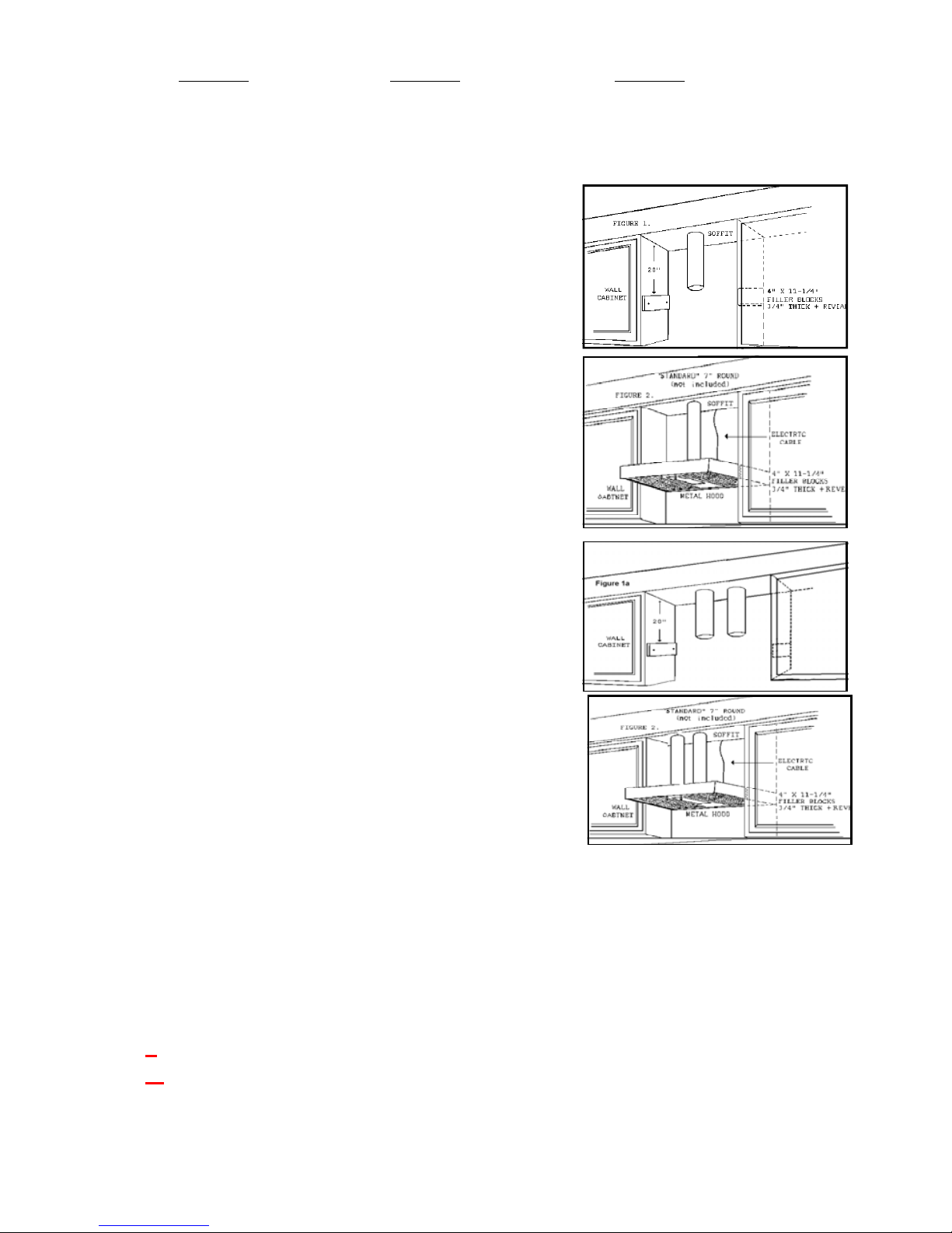
1. Scribe line below top of cabinet to meet with bottom of
hood. Repeat on the opposite cabinet. (Figure 1)
2. Position 4” x 11 1/4” x 3/4” wood block flat on side of
cabinet with end of filler block against wall and secure
with screws. Remove Filters.
3. Raise and position Power Liner so that bottom is level with
scribed lines on cabinets and drive screws through holes in
the ends of the Powered Liner. (Figure 2)
Use our exclusive positioning kit if needed. The duct pipe
or pipes should slip into the Automatic Seal Vent Collar.
Be sure to remove the black tape that holds the Damper
blades closed. *It is NOT recommended to use 2
dampers during installation. You have the option to put a
external damper or use the existing damper already
on the unit.
4. If required additional mounting at the Rear of unit:
Locate wall studs, drill holes through back of Powered
Liner to hit studs and attach the Liner to the wall with
screws.
5. Island and Peninsula Powered Liners should be mounted in
the same way except there will be no rear wall mount.
6. Bring conduit down 4” past the bottom of the liner.
Note: Top box for the C2000BP1 shows vent opening
Off set to the left (facing the hood).
7. Remove junction box cover from the C2000. (Be sure to
comply with all local electrical and safety Codes).
8. Hook up electrical wires and secure reattach junction box.
9. Replace junction box cover. Install lights and replace
filters. For Baffle Filters, install grease tray towards the back
of liner. Take one baffle, slide between steel strips towards
the front of the liner and push back into grease tray grooves,
then slide to one side. Insert second baffle the same way and
slide to opposite side. (Grease holes, on bottom of baffle
must be inserted into grease tray) Take Center Panel and Slide
in towards the front of the liner and push back into grease tray.
10. TWIN UNITS ONLY - Transitioning two pipes into one is NOT recommended. CFMs are
reduced by 25% and the Performance warranty will be void.
*Baffle Units Only - top box dimension is 6” high.
Duct Sizes Indicated in Model # (Ex: C2036PS-8-SS)
** - 8 = 8” DUCT PIPE
** - K=10” DUCT PIPE
Page 4

Powered Liners Installation Detail Continued:
Figure 1:
Figure one shows the included
elbow transition from 7” diameter
round to 3 1/4” x 10” rectangular.
This transition is used to return the
filtered air back to inside the
kitchen either through the canopy
face of if applicable the soffit
above. The customer must provide
the appropriate length of straight
7” round ducting that connects the
hood exhaust to the elbow
transition.
Figure 2
Figure two shows a typical air exit
terminating through the canopy
face. A customer supplied,
decorative 4” x 10” register cover
face plate should be used to finish
off the cut out opening.
Figure 3
Figure three shows a typical air exit
terminating through the soffit face
directly above the hood canopy.
Again the customer must provide
a 4” x 10” register face plate.
Re-Circulating, (Non-Vented) Series: C2000SD2-NV
For use when unable to terminate exhaust ducting to outside the structure.
NOTE: The C2000 NV Unit comes supplied with charcoal filters that will
accumulate the cooking grease and over time decrease the hoods
performance. The amount and style of cooking will dictate how often the
filters should be replaced. This type of filter is designed for replacement
only. Contact Imperial to purchase proper replacement filters.
The C2000SD2-NV requires one 50 Watt Halogen (Par 20) light that must
be purchased separately.
View from rear of the canopy.
Canopy Exit
Soffit Exit
Included
Not Included
Figure 1
Figure 2
4” x 10” Cover
Face Plate
4” x 10” Cover
Face Plate
Figure 3
Page 5

Imperial Cal Products, Inc.
To order replace parts or schedule service please call our office at
(800) 851-4192 or use our website… www.imperialhoods.com.
PARTS:
When ordering Parts we need the following information:
Model Number (not serial number) found on UL label inside hood.
Exact dimensions (in the case of filters)
You can find the model number on the inside of your hood on our UL label.
There will be a several model numbers listed, your model number should
have a colored dot or mark next to it to indicate the exact model you have.
In the case of Filters, we will need the exact dimensions of the filter needed.
Indicate which side has the pull tabs on it. Filters are not a warranty
replacement part. With care your filters should last many years.
Payment on Parts is handled one of three ways: PrePaid (you send a check
prior to our Shipping), call with credit card information, VISA or MasterCard,
COD or Cash if you decide to “Will Call”. Our Will Call hours are 8:30 to
3:30, Monday through Friday.
SERVICE:
When calling in for Service we need the following information:
Model Number (not serial number)
Proof of Purchase
Name of company you purchased the hood through.
Name & Phone number of the person to contact to set up the service
call.
Full address of the location where service is to be done.
Warranty is Seven Years, Parts and Labor.
Page 6

Maintenance & Warranty Information
RANGE HOOD CLEANING—When cleaning a painted hood, wash it with mild, soapy water
ONLY! Wipe the hood thoroughly with clean water and dry with soft cloth. When cleaning
Stainless Steel use a cleaner specifically for Stainless Steel. Always rub with the grain using
non-abrasive cleaning materials. AVOID detergents, disinfectants or cleaning products in aerosol
cans. NEVER use abrasive scouring powders on your hood! Some cleaning chemicals may
damage the hood finish!
BAFFLE FILTER CLEANING—To remove Baffle Filters, remove center panel by pulling panel
toward the front of the hood, lift up to remove. Move filters to the center of the hood, pull baffle
towards the front of the hood and lift out. To remove grease tray, slide tray to the top of the hood and
lift out. Grease will accumulate in grease tray. Clean with hot water and polish
with stainless steel cleaner.
SLIM BAFFLE & ALUMINUM MESH FILTER CLEANING
Clean filters often for the best performance. How often depends on cooking style. Use hot water
and a degreaser to clean. May be used in the dishwasher through the
RINSE cycle ONLY. Some detergents may discolor filters. For Slim
Baffles polish baffle side with stainless steel cleaner.
LIGHTING
50 Watt Halogen Flood (Par 20—Medium Base) OR 9.5
Watt LED Flood=50W (Par 20=50 Watt Halogen Equivalent/
Dimmable)
*SD4-12 ONLY—8.5 Watt LED Dimmable or 75 Watt Max.
Incandescent (Behind grease filters)
***Bulbs not included on any model.***
Warning: Do not use any bulbs that are not instructed by manufacturer. Do not use Halogen bulbs in
sockets not intended for their use! They are to be used only in the Front Light and Center Light
Panels.
Your Imperial Warranty: Proof of original purchase date is needed to obtain
service under warranty.
Deluxe Units: Seven Year Limited Warranty, Parts and Labor in the Continental USA.
Parts only outside the United States.
For seven years from date of original purchase, we will provide parts and service labor in your home
to repair or replace any part of the hood that fails due to a manufacturing defect.
Call for service at (800) 851-4192
NOTE: Service companies will perform Warranty Service, Monday through Friday from
7 a.m.—4: p.m. The service company will call and schedule a date and time with a 4 hour window.
If the service company arrives at your location, during the scheduled date and time, and no one is
home, you will be charged a trip charge by the service company for a return service call.
ITEMS IMPERIAL WILL NOT PAY FOR
1. Service calls to correct the installation of your appliance, to instruct you how to use your
appliance, to replace or repair house fuses or the correct housing wiring or plumbing.
2. Service calls to repair or replace appliance light bulbs or filters.
3. Repairs when your appliance is used for other than normal, single-family household use.
4. Damage resulting from accident, alteration, misuse, abuse, fire, flood, acts of God, improper
installation, installation not in accordance with electrical or plumbing codes.
5. Replacement parts or repair costs for units operated outside the United States.
6. Pickup and delivery. This appliance is designed to be repaired in the home.
7. Repairs to parts or systems resulting from unauthorized modification made to the appliance.
8. Expenses for travel and transportation for product service in remote locations.
9. The removal and reinstallation of your appliance if it is installed in an inaccessible location or is
not installed in accordance the published installation instructions.
10. Replacement parts or repair labor costs when the appliance is used in a country other than the
country in which it was purchased.
3”
LED HALOGEN
Page 7

SAFETY INSTRUCTIONS
Read and Save These Instructions
Warning: To reduce the risk of fire, electrical shock or injury to persons, observe the
following:
A. Use this unit only in the manner intended by the manufacturer. If you have any questions,
contact the manufacturer. Before servicing or cleaning unit, switch power off at service panel and
lock Service Disconnecting Means to prevent power from being switched on accidentally. When
the Service Disconnecting Means cannot be locked, securely fasten a prominent warning device,
such as a tag, to the service panel.
Warning: To reduce the risk of a range top grease fire:
A. Never leave surface units unattended at high settings. Boil-overs cause smoking and greasy
spillovers that may ignite. Heat oils slowly on low or medium settings.
B. Always turn hood ON when cooking at high heat or when Flambéing foods (i.e. Crepes
Suzette, Cherries Jubilee, Peppercorn Beef Flambé).
C. Clean ventilating fans frequently. Grease should not be allowed to accumulate on fans or
filters.
D. Use proper pan size. Always use cookware appropriate for the size of the surface element.
Warning: To reduce the risk of injury to persons in the event of a range top
grease fire, observe the following:
A. SMOTHER FLAMES with a close-fitting lid, cookie sheet or metal tray, then turn off the
burner. BE CAREFUL TO PREVENT BURNS. If flames do not go out immediately,
EVACUATE AND CALL THE FIRE DEPARTMENT.
B. NEVER PICK UP A FLAMING PAN - you may be badly burned.
C. DO NOT USE WATER, including wet dishcloths or towels, violent steam explosion will
result.
D. Use an extinguisher ONLY if:
You know you have a Class ABC extinguisher and you already Know how to use it.
The fire is small and contained in the area where it started.
The fire department is being called.
You can fight the fire with your back to an exit.
Warning: To reduce the risk of fire, electrical shock or injury to persons, observe the
following:
A. Installation work and electrical wiring must be done by a qualified person or persons in
accordance with all applicable codes and standards, including fire-rated construction.
B. Sufficient air is needed for proper combustion and exhausting of gases through the flue of
fuel burning equipment to prevent back drafting. Follow the heating equipment
manufacturer’s guideline and safety standards such as those published by the National Fire
Protection Association (NFPA), and the American society for Heating, Refrigeration & Air
conditioning Engineers (ASHRAE), and the local code authorities.
C. When cutting or drilling into a wall or ceiling, do not damage electrical wiring and other
hidden utilities.
D. Ducted fans must always be vented to the outdoors.
Warning: To reduce risk of fire, use only Smooth Metal Ducting!
PROPERTY OF HOME OWNER, PLEASE DO NOT THROW AWAY!
REV. 9/14
Page 8

Page 9

WARRANTY CARD
To better serve you with your service and warranty
needs, please fill out the purchase and product
information and return to Imperial Cal Products.
CUSTOMER NAME:_________________________________________________
PURCHASED FROM:________________________________________________
PURCHASE DATE:__________________________________________________ MODEL #:__________________________________________________________ SERIAL #___________________________________________________________
(Serial # beneath filters on white label)
Warranty card can be submitted via our website at:
www.imperialhoods.com or by mail.
Please keep receipt. Proof of original purchase date is needed to
obtain service under warranty.
Mail warranty card to:
Imperial Cal Products
ATTN: Warranty Department
425 Apollo St.
Brea, CA 92821
Or visit our website to complete warranty registration:
www.imperialhoods.com
 Loading...