

Imperial KWIK-COUPLER Instructions Manual
INSTRUCTIONS FOR KWIK-COUPLER™
CHARGING HOSE
U.S. Patent No. 4,458,719
CAUTION
WHEN SERVICING REFRIGERATION OR AIR-CONDITIONING SYSTEMS,
IMPROPER PROCEDURES CAN CAUSE REFRIGERANT GAS UNDER PRESSURE
TO VIOLENTLY EXPLODE. PRECAUTIONS MUST BE OBSERVED TO PROTECT
BOTH THE PERSON DOING THE WORK AND THE EQUIPMENT INVOLVED.
THIS SERVICE DEVICE IS INTENDED FOR USE ONLY BY PROFESSIONAL
SERVICE PEOPLE WHO ARE FAMILIAR WITH THE EQUIPMENT BEING
SERVICED AND THE PRECAUTIONS NECESSARY TO SAFELY COMPLETE THE
INTENDED SERVICE OPERATIONS IN ACCORDANCE WITH THESE
INSTRUCTIONS. FOR USE ONLY WITH REFRIGERANTS 12, 22, 500, 502, AND 134a.
APPLICATION INFORMATION
The Kwik-Coupler™ hose set is intended for use with refrigeration air conditioning service manifold
high (red), low (blue), and accessory (yellow) side service fittings. Conventional threaded connecting is
converted to push-pull operation which is faster, easier, and positive sealing at all times. The high and
low side Kwik-Couplers™ are intended for use when connecting to core valve-type fittings. Valve cores
are depressed automatically without adjustments or loss of refrigerant. The accessory side
Kwik-Coupler™ is intended for use when connecting to equipment, such as a tank or vacuum pump,
that does not utilize core valve-type fittings. The automatic shutoff valve in the hose is opened when the
Kwik-Coupler™ is engaged.
An automatic shutoff valve retains refrigerant pressure in a disconnected hose. This feature permits
transferring the high side hose refrigerant through the service manifold into the low side, thereby
eliminating waste and hazardous high pressure discharge. Hoses can also be stored under low side
pressure to prevent contamination, if desired.
Imperial Kwik Coupler Charging Hose can be obtained with SAE 1/4” connections, or with female coupler for
connecting to automotive air conditioning high side service fittings, utilizing a smaller 3/8-24 thread.
WARNING -- DO NOT ALLOW ANY REFRIGERANT CAN, CONNECTED
FOR CHARGING TO BE EXPOSED TO SYSTEM HIGH SIDE
PRESSURE - CAN EXPLOSION COULD RESULT.
PROP 65 WARNING: This product contains chemicals, including lead,
known to the State of California to cause cancer, and birth defects or
other reproductive harm. Wash hands after use.
Replacement Parts
08920261
Female coupler
(High Side-Automotive)
& Low Side Female Couplers
08920071
Sleeve
High Side - Automotive
08920077
O-Ring
(Lubricate)
08920072
Retainer
08920074
Female coupler
(Low Side)
05951125
Female coupler
(Accessory Side)
Identification Groove
Accessory Side Female Coupler
05951126
Sleeve
08920077
O-Ring
(Lubricate)
08920072
Retainer
08920263
High Side
O-Ring
Operating Instructions
1. No adjustment of valve core depressor is required.
2. Thread female coupler onto core valve service fitting - use finger tight torque.
3. To connect, engage couplers and push inward until spring loaded clip on male coupler engages slot on female
coupler. On systems with core valve-type fittings engagement is complete, and the manifold gauge should read
system pressure. On accessory equipment, such as storage tanks, that utilizes manual valves, the valves
should be opened after engaging the Kwik-Couplers™. The manifold gauge will then read system pressure.
4. Before disconnecting, the manual valves on accessory equipment should be closed. To disconnect
Kwik-Couplers™, depress spring loaded clip on male member and pull outward. An automatic shutoff in the
male coupler member will maintain the disconnected hose under pressure. High pressure can be transferred
through the manifold into the low side of the system. Hoses can be stored under low pressure or discharged
into an approved container.
DO NOT DISCHARGE REFRIGERANT INTO ATMOSPHERE UNDER PENALTY OF LAW.
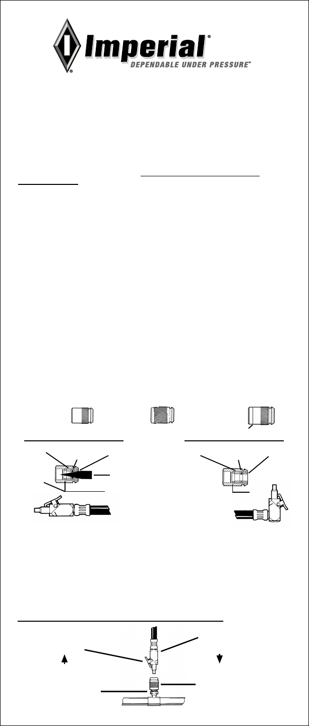
Connecting
Illustration
Disconnect
(Depress)
System Access Fitting
Tapered Object
08920073
Low Side Gasket
To replace, insert tapered object (pen or pencil) and
press against threaded retainer and unscrew. Install
new seal and tighten to zero clearance plus 1/8 turn.
Charging Hose
with attached
Male Coupler
Connect
Female Coupler
08920073
Gasket

CHARGING HOSE & ACCESS FITTING
INSTRUCTION FOR
ADJUSTABLE BRASS CORE DEPRESSOR
APPLICATION INFORMATION:
THE ANGLED END OF IMPERIAL CHARGING HOSES AND SWIVEL END
OF ACCESS FITTINGS ARE EQUIPPED WITH A THREADED NIPPLE AND
DEPRESSOR THAT PERMITS ADJUSTING THE DEPRESSOR TO MATCH THE
POSITION OF SYSTEM ACCESS FITTING CORE VALVES FOR A PROPERLY
SEALED CONNECTION EVERY TIME.
FOR A CORE VALVE RECESSED BELOW THE END OF THE ACCESS FIT-
TING, POSITION THE DEPRESSOR AN EQUAL AMOUNT ABOVE THE GASKET
END.
FOR A CORE VALVE PROTRUDING ABOVE THE END OF THE ACCESS
FITTING, POSITION THE DEPRESSOR AN EQUAL AMOUNT BELOW THE
GASKET END.
IMPORTANT
ADJUSTABLE DEPRESSOR
CAN ONLY BE INSTALLED
IN ANGLED END OF CHARGING
HOSES
ADJUSTABLE
BRASS
DEPRESSOR
CORE VALVE
REMOVAL CAP
(LONG NOSE PLIERS OPTIONAL)
RUBBER
GASKET
ADJUST BY ROTATING
REPLACEMENT
DEPRESSORS
ADJUSTABLE
BRASS
DEPRESSOR
REPLACES
ADJUSTABLE
NON-METALLIC
DEPRESSOR
ADJUSTING PROCEDURE:
THE BRASS CORE DEPRESSOR CAN BE ADJUSTED WITH AN ORDINARY
VALVE CORE REMOVAL CAP OR LONG NOSE PLIERS.
TO MAKE AN ADJUSTMENT, SIMPLY ENGAGE TOOL WITH END OF
DEPRESSOR AND ROTATE FOR THE DESIRED INWARD OR OUTWARD
ADJUSTMENT.
REPLACEMENT DEPRESSORS:
THE BRASS CORE DEPRESSOR CAN BE USED AS A REPLACEMENT IN
IMPERIAL CHARGING HOSES AND ACCESS FITTINGS THAT WERE ORIGINALLY
EQUIPPED WITH A NON-METALLIC ADJUSTABLE DEPRESSOR.
TO REPLACE DEPRESSOR, BACK OUT OLD DEPRESSOR. IF OLD
DEPRESSOR IS DAMAGED AND WILL NOT BACK OUT THROUGH GASKET,
REMOVE GASKET AND THEN THE DEPRESSOR.
TO INSTALL NEW DEPRESSOR, INSERT DEPRESSOR INTO RUBBER
GASKET AND ROTATE WHILE APPLYING INWARD FORCE. ADJUST TO
DESIRED POSITION.
30333 Emerald Valley Parkway • Glenwillow, Ohio 44139 USA
www.imperial-tools.com • info@stridetool.com © 2011 Stride Tool Inc.
PART NO. P0000432_E
 Loading...