

Page 1
OWNERS MANUAL
WARNING: Improper installatio n, adjustment,
FOR YOUR SAFETY
INSTALLATION, OPERATION, & MAINTENANCE INSTRUCTIONS
®
1128 Sherborn Street ▪ Corona, CA 92879-2089 ▪ (951) 281-1830 ▪ FAX (951) 281-1879
IR SERIES – RANGES & OVENS
and for installation in accordance with ANSI Z223.1/NFPA 54 ( la te st edition) of the National Fuel Gas Code, the
National Gas Installation Code, CSA/B149.1 or the Propane Installation code , CSA/B149.1, as applicable. Copies
may be obtained from the American Gas Association, 1515 Wilson Blvd, Arlington, VA 22209.
alteration, service or maintenance can cause property
damage, injury or death. Read the ins ta lla tion,
operating and maintenance instructions thoroughly
before installing or servicing this equ ipment.
Instructions to be followed in case the user smells gas are to be posted in a prominent location in the
kitchen area. This information shall be obtained by contacting the local gas company or gas supplier.
IMPORTANT
Safe and satisfactory operation of your equipment depends to a great extent on its proper installation.
Installation must conform to local codes, or in the absence of local codes, with the National Fuel Gas Code ANSI
Z223.1/NFPA 54 , the National Gas Installation Code, CSA/B149.1or the Propane Installation code, CSA/B149.1, as
applicable.
All Imperial Mfg. Co. equipment is manufactured for use with the type of gas specified on the rating plate
PLEASE RETAIN THIS MANUAL FOR FUTURE REFERENCE
DO NOT STORE OR USE GASOLINE OR OTHER
FLAMMABLE VAPORS OR LIQUIDS IN THE
VICINITY OF THIS OR ANY OTHER
APPLIANCE
.
Imperial cooking appliances are restaurant grade. Ranges are free standing and available in widths from
two to six feet. A large number of different range top arrangements are assembled over one or two ovens or a
cabinet base. Installation is the same for any range top regardless of whether it has an oven below or not; in like
manner, installation is the same for all cooking equipment regardless of t he top arrangement. This unit may also be
equipped with a salamander broiler. A Cheesemelter may be mounted on the high shelf as long as the Broiler is not
wider than the range.
IMPORTANT
Installing, Operating and Service Personnel:
Installation of the equipment should be performed by qualified, certified, licensed and/or authorized
personnel who are familiar with and exp e rienced in state/local installation codes. Operation of the equipment should
be performed by qualified or authorized personnel who have read this manual and are familiar with the function of
the equipme nt. Service of the equipment should be performed by qualified personnel who are knowledgeable with
Imperial Ranges
1
Page 2

SHIPPING DAMAGE CLAIM PROCEDURE
The equipment is inspected & crated carefully by skilled personnel before leaving factory. The transportation company
assumes full responsibility for safe d e livery upon acceptance of this equipment. If shipme nt arrives damaged:
1. Visible loss or damage: Note on freight bill or express delivery and have signed by person making delivery.
2. File claim for damages immediately: Regardless of extent of damages.
3. Concealed loss or damage: If damage is noticed after unpacking, notify transportation company immediately and file
“Concealed Damage” claim with them. This should be done within fifteen (15) days from date delivery is made to
you. Retain c ontainer for inspecti on.
GENERAL
(1) A manual gas shut -of f valve must be installed in the gas supply (service) line ahead of the appliance and
gas pressure regulator in the gas stream for safety and ease of future service.
(2) The gas pressure regulator supplied must be installed on the appliance prior to connecting the equipment to
the gas line. Failure to install a regulator will void the equipment warranty and r e sult in a potentially
hazardous condition.
(3) The appliance and its individual shut off valve must be disco nnected from the gas supply piping system
during any pressure testing of the s ys t em at test p ressures in excess of ½ PSI.
(4) The appliance must be isolated from the gas supply piping system by closing its individual manual shut off
valve during any pressure testing of the gas supply piping system at test pressures eq ual to or less than ½
PSI.
(5) Please contact the factory, the factory representative, or a local service company to perform maintenance
and repairs.
RATING PLATE
The rating plate is located in front of the range below the oven section (7” from the floor). Information on
this plate includes the model and serial numbers. When communicating with factory about a unit or requesting
special parts or information, this da ta is essential for proper identification. Other information on this plate is the
BTU/hr input of the burners, operating gas pressure in inches WC, a nd whether the unit is orificed for natural or
propane gas. Pilot lighting instructions (ovens only) are also located in the same area. The Salamander broiler or
Cheesemelter (if provided) is supp lied with its own rating plate located on the unit.
IMPERIAL COOKING APPLIANCES MUST BE CONNECTED
ONLY TO THE TYPE OF GAS IDENTIFIED ON THE RATING PLATE
CLEARANCES
The appliance area must be kept free and clear of all combustibles. This unit is design-certified for the following
installations only:
The clearances from combustible and noncombustible construction for ranges and range mounted Salamander
broiler or Cheesemelter are as follows:
Combustible Noncombustible
Back 4” 0
Sides 8” 0
If legs or casters are not used, the unit must extend 2” beyond the front edge of a noncombustible curb or platform.
2
Page 3

CAUTION
DO NOT PUSH against the end of the valve cover/landing ledge in an attempt to adjust the ranges position.
Although this part is de burred during manufacturing, an ac cident coul d occur if the range should move suddenly
HIGH SHELF ASS EMBLY
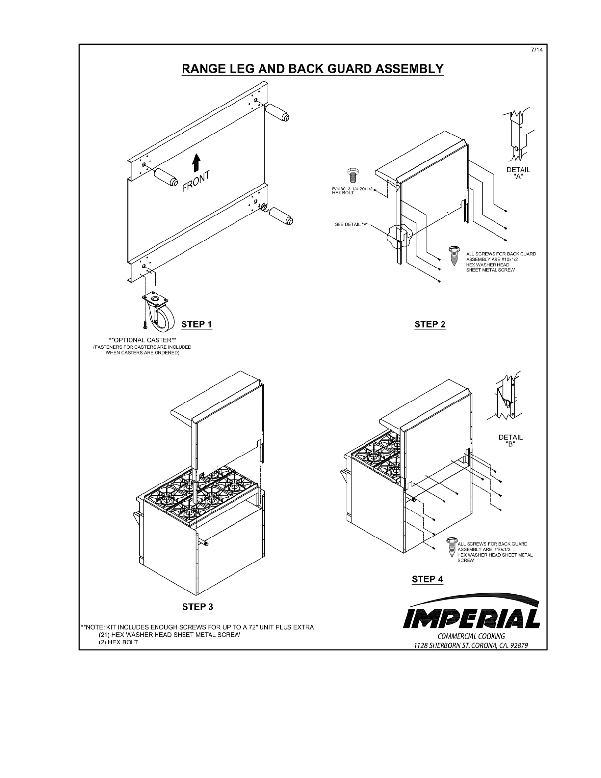
(1) Mount the blackguard to the range with #10 sheet metal screws.
(2) Mount the high shelf to the blackguard with #10 sheet metal screws provided (see attachment at the end of
this manual for a diagram that describes the installation of the blackguar d/flue riser).
NOTE: If a Salamander broiler/Cheesemelter is to be mounted on range, read installation instructions for
Salamander broiler/Cheesemelter before installing high shelf. Special care must be taken to ensure that the gas
supply piping and/or gas pressure regulator is not exposed to exhaust gases or elevated temperatures.
LEVELING
A carpenter’s level should be placed on the center across the range top and the unit leveled both front-toback and side-to-side. If it is not level, cakes, casseroles, and any other liquid or semi-liquid batter will not bake
evenly, burner combustion may be e rratic and the unit will not function efficiently. Except griddles which need to
slope forward 1/8” – ¼”.
while being pushed into position by hand.
If the floor is relatively smooth and level, the unit may be f urther leveled with adjustment in the foot of the
leg. Adjust to the high corner and level the unit with metal shims if the adjustment required exceeds the 1 ¼”
adjustment available. Units with casters must be leveled with shims. A unit will probably not return to the same
position after being moved, requiring re-leveling after each move.
AIR SUPPLY & V ENTILATION
The area in front of, around, and above the appliance must be kept clear to avoid any obstruction of the
flow of combustion and ventilation air. Adequate clearance must be maintained at all times in front and at the sides
of the appliances for servicing and proper operation.
Means must be provided for any commercial, heavy-duty cooking appliance to exhaust combustion waste
products to the outside of the build ing. Usual practice is to place the unit under an exhaust hood. Filters and drip
troughs should be part of any industrial hood, but consult local codes before construction and installing a hood.
Strong exhaust fans in this hood or in the overall air conditioning system can produce a slight vacuum in
the room and/or cause air drafts, either of which can interfere with pilot or burner performance and can also be hard
to diagnose. Air movement should be checked during installation; if pilot or burner outage problems persist, makeup air opening or baffles may have to be provided in the room.
CONVECTION OVEN – ELECTR ICAL CONNECT ION
Imperial ranges with CONVECTION OVEN requires a 120 volt supply to operate the ignition systems and
circulating fan. The supply cord provided on the appliance is equipped with a three prong (grounding) plug for
protection against shock hazard. The electrical service in the building must be equipped with a properly grounded
three prong receptacle, in accordance with local codes, or in the absence of local codes, with the National Electrical
Code, ANSI/NFPA 70 or the Canadian Electrical Code, CSA C22.2, as applicable. Do not cut or remove the
grounding prong from this plug. Wiring diagram is located on the backside of the side control panel. Disconnect
power supply before cleaning or servicing.
3
Page 4

NOTE: This appliance is not capable of being operated in the event of power failure. No attempt should be
made to operate this appliance during a power failure.
GAS CONNECTION
NOTE: The gas supply (service) line must be the same size or greater than the inlet line of the appliance. Imperial
ranges and ovens use a ¾” NPT inlet. Sealant on all pipe joints must be resistive to LP gas.
MANUAL SHUT-OFF VALVE
This installer –supplied valve must be installed in the gas service line ahead of the appliance and regulator
in the gas stream and in a p osition where it can be reached quic kly in the event of an emergency.
PRESSURE RE GULATOR
All commercial cooking equipment must have a pressure regulator on the incoming service line for safe
and efficient operation, since service pressure may fluctuate with local demand. The manual shut-off valve is
normally supplied by the installer, however, a pressure regulator is packed inside each Imperial range.
Failure to install a pressure regulator will void the equipment warranty
The regulators supplied for Imperial ranges, have ¾” inlet/outlet openings and are adjusted at the factory
for 5” WC (natural gas) or 10” WC (p ropane) depending on the c ustomer’s ordering ins tructions.
Prior to connecting the regulator, check the incoming line pressure, as these regulators can only withstand a
maximum pressure of ½ PSI (14” WC). If the line pressure is beyond this limit, a step-down regulator will be
required. The arrow forged into the bottom of the regulator body shows gas flow direction; it should point
downstream to the appliance. The air vent cap on the top regulator is part of the regulator and should not be
removed.
Any adjustments to regulators must be made only by qualified service personnel with the proper test
equipment.
RIGID CONNECTIONS
Double-check any installer-supplied intake pipes visually and/or blow them out with compressed air to
clear any dirt particles, threading chips, or other foreign matter before installing a service line. Those particles will
clog orifices when gas pressure is applied.
All connections must be sealed with a joint compound suitable for LP gas and all connections must be
tested with a soapy water solution be fore lighting any pilots.
FLEXIBLE COUPLINGS, CONNECTORS AND CASTERS
If the unit is to be installed with flexible c ouplings and/or quick-discon nect f ittings, the installer must use a
heavy-duty, AGA design-certified commercial flexible connector of at least ¾” NPT (with suitable strain reliefs).
The flexible connector must comply with the standard for Connectors for Movable Gas Appliances, ANSI Z21.69
(or latest edition) CSA 6. 16 (or latest edition) and a quick-disconnect device that complies with the standard for
quick-disconnect devices for use with Gas Fuel should comply with ANSI Z21.41(or latest edition) CSA 6.9 (or
latest edition). If disconnection of the restraint is necessary, make sure to reconnect restraint after the appliance has
been returned to its originally insta lle d position. Domestic gas or water connectors are not suitable.
Restraining device may be attached to the back frame/panel of the unit.
4
Page 5
If the unit is to be installed with casters, a flexible connector must be used and the same ANSI standards
CAUTION
apply. Locking front casters are provided to limit the movement of the appliance without depending on the
connector or associated piping. A suitable strain relief must be installed with the flexible connector.
All connections must be sealed with a joint compound suitable for LP gas and all connections must be
tested with a soapy water solution be fore lighting pilots.
INITIAL PILOT LIGHTING
When lighting pilots and checking for leaks, do not Stand with your face close to the combustion chamber
All Imperial Mfg. appliances are adjusted and tested before leaving the factory, effectively matching them
to sea level conditions. Adjustments and calibrations to assure proper operation may be necessary on installation to
meet local conditions, low gas characteristics, to correct possible problems caused by rough handling or vibration
during shipment, and are to be performed only by qualified service personnel. These adjustments are the
responsibility of the customer and/or dealer and are not covered by our warranty.
Check all gas connections for leaks with a soapy water solution before lighting any pilots. DO NOT USE
AN OPEN FLAME TO CHECK FOR LEAKS! Putting an open flame beside a new gas connecti on is extremely
dangerous. Before lighting any pilots, make sur e that burner valves and thermostats are turned “off”.
A. TOP BURNER/RAISED GRIDDLE-BROILER
All top section burners are equipped with constant-burning pilots. These are to be manually lighted
immediately after the gas is turned on and the system is checked for leaks. Burner pilots are proved for each
burner and can be rechecked for proper adjustment. Adjustments can be made with a screwdriver to the brass
pilot valve accessible through the valve cover.
B. HOT TOP
The pilot should be lighted immediately after the gas is turned on and the system is checked for leaks. The
pilot can be reached with a long match through the valve cover, or by lifting the plate upward and accessing
through the t op.
C. GRIDDLES
The griddle pilot is ignited in the same fash ion as the Hot Top section, using a long lig hted match placed
through the front control panel opening. Adjustment of the pilot flame can be made with a screwdriver to the
pilot valve, accessible through the valve cover.
For detailed service instructio ns to adjust by-pass (minimum burner) flame and to recalibrate oven
and griddle thermostatic controls, see attachment at the end of this manual.
D. STANDARD OVEN
Pilot gas is tapped from the thermostat, routed through tubing to a pilot burner.
Oven pilot lighting or relighting is to be completed in the following seq uence:
(1) Turn the oven thermostat knob to “off” and wait 5 minutes.
(2) Remove the oven’s lower kick plate by lifting up and out. This exposes the pilot bur ner.
(3) Make sure any accumulated gas has dispersed. Since propane gas is heavier than air, check near the
floor area for the odor of propane gas before attempting to light any pilot burner s.
(4) Rotate thermostat to pilot position and depress and hold it in throughout the lighting procedure.
(5) Light pilot burner.
(6) Continue to depress the thermo stat until the pilot remains lit when released .
(7) If pilot is extinguished, repeat steps 4 through 6 above.
5
Page 6

(8) Turn the oven thermostat knob “on” and set to desired temperature setti ng, watch to make sure the
oven burner ignites from the pilot and that there are no yellow flames from the burner.
(9) Turn the oven thermostat to “pilot” and replace the lower kick plate.
NOTE: It may be necessary to relight the pilot several times until the lines are purged of any trapped air and a
constant gas flow is attained.
E. CONVECTION OVEN
(a) Turn the thermostat dial to the “OFF” position. p lace the power switch to the “OFF” position.
(b) Wait 5 minutes.
(c) Place power switch to the “ON” position. Turn the oven thermostat to the desired te mperature.
(d) For a complete shutdown, place the thermostat and power switch in the “OFF” position.
TO CHECK FOR LEAKS
(1) Remove the kick plate (See #2 above).
(2) Check pilot tubing and burner tubing for leaks where they en ter the gas valve with a soapy water solution.
(3) Light the pilot as described above.
(4) Check the connection of the pilot t ubing leaving the gas valve with a soapy water solution.
(5) Turn the thermostat to any setting and burner shoul d light.
(6) Check the burner orifice elbow connection downstream of the safety valve with a soapy water solution.
(7) Check the burner visually for blue flame. There s hould be no yellow tips or soot. If yellow tipping occurs,
call an authorized service person to adjust the burner air shutter.
FINAL PREPARATION
A. TOP SECTION
New units are wiped clean with solvent s a t the factory to remove any visible signs o f dirt, oil, or
grease remaining from thin film or nontoxic rust protectant. Food preparation surface should be washed
thoroughl y with hot, soa py water b efore being used.
The top grates should be removed and washed before use. With these removed, it will be possible
to remove any plastic tie cords hol ding the bur ners in place.
B. GRIDDLE
New griddles should be s easoned following this sequence:
(1) Clean the griddle surface thoroughly with hot, soapy water to remove the protective oil coating wiped
on at the factory.
(2) Rinse with a mixture of ¼ cup vinegar to one quart wa ter.
(3) Spread unsalted solid shortening or liquid frying compound evenly over the entire gridd le surface.
(4) Turn all griddle burners to “medium” or thermostats to 350 degrees and wait until the shortening
begins to smoke, then turn the burners “off”.
(5) Rub the now-melted shortening into t he griddle s urface with burlap, moving in the direction of the
surface’s polish marks and covering the entire surface.
(6) Let the griddle cool, then repeat steps 3,4, & 5.
(7) When the griddle is cool after the sec ond seasoning, wipe it once again with a thin fil m of shorteni ng
or cooking oil.
C. HOT TOP
These should be washed in place to remove the solvent and oil fi lms, then given a light coating of
cooking oil before being used for food preparation. To remove the hot top, use a flat tip screwdriver as a
lever in fro nt.
D. OVENS
On initial i ns tallation, turn the o ven to 250 degrees and operate for about 1 hour, then reset the t hermostat
to its maximum and operate for another hour. This will drive off any solvents remaining in the unit. At the
end of this second hour, t urn the thermostat OFF, open the door and allow the unit to cool. Oven should
then be thoroughly was hed using hot, soapy water before being used.
6
Page 7
CLEANING AND MAINTENANCE
CAUTION
Any piece of equipment works better and lasts longer when maintained properly. Cooking equipment is no
exception. Your Imperial range and oven must be kept clean during the working d ay and thoroughly clea ned at the
end of the day.
DAILY:
OPEN BURNERS:
1. Lift all the open grates.
2. Lift off the burner heads and venturies by raising the head slightly, sliding to the rear of the range and
lifting upwards.
3. Wash all of the above in hot, soapy water.
4. Reinstallation of the top burners is the reverse of removal.
GRIDDLES:
1. Scrape with a nylon griddle scrapper to remove cooked on spills. Use a fine grained stone only when
absolutely necessary.
2. Wipe away any griddle stone dust and food particles with burlap.
3. Wash with hot, soapy wate r, then rinse with vinegar and water.
4. Rinse again with clear water.
5. Re-oil with shortening or liquid frying compound.
6. DO NOT FLOOD A HOT GRIDDLE WITH COLD WATER! This promotes griddle warping and can
cause the griddle to crack if continued over a long period of time.
NEVER USE AMMONIA IN AN OVEN THAT IS WARMER THAN
ROOM TEMPERATURE AND ALWAYS HAVE DIRECT VENTALATION!
HOT TOPS:
1. Scrape off any food spills.
2. Wash with hot, soapy water then rinse and lightly oil.
ALL OVENS AND SALAMANDER BROILERS:
1. Remove the baking racks. Wash in hot soapy water and replace after the rest of the oven is cleaned.
2. Remove the oven botto m by lifting it out from the front then s l iding forward, out of the oven.
3. Scrape off any food particles with a nylon griddle scraper. Be very careful about scratching the porcelain
finish on the oven liner panels.
4. Wash all the above with hot soapy water, then reassemble.
5. Baked on spills may be loosened and stubborn stains removed with ordinary household ammonia and
scrubbing with a nylon pad in a cold oven only.
6. Do not allow spray type oven cleaners to come into contact with the temperature probe in the oven.
7. After cleaning the oven, rinse well with ¼ cup of vinegar to one quart of clear water solution to neutralize
any caustic residue of the cleaning compound. Wipe dry.
8. Infra-red burners, available on ICMA Cheesemelters and ISB Salamanders are self cleaning. The use of
any solvents or wire brushes may damage tiles.
7
Page 8

CONVECTION OVEN:
9. To increase the life of the motor follow these instructions:
a. Never run oven with motor off.
b. After you finish cooking and the oven is not to be used for more than ½ hour, place the toggle s witch
to the “COOL DOWN” position and open the door. When oven temperature is equal to room
temperature turn unit off.
PERIODIC CLEANING:
Check the ventilation system per iodically to se e that nothing has fallen down into t he stub back, high riser
or high shel f exhaust ve nts.
Lubricate the pivot pins of the oven door hinge where the right and left arms connect to the door. Use a
multipurpose lubricating oil sparingly so as to not drip oil needlessly.
Your Imperial range should be checked for safe and efficient operation at least yearly by a qualified service
company.
STAINLESS STEEL:
All stainless steel body parts should be wiped regularly with hot soapy water during the day and with a
liquid cleaner designed for this material at the end of each day. DO NOT USE steel wool. Abrasive cloths, cleansers
or powders to clean stainless surface! If it is necessary to scrape stainless steel to remove encrusted materials, soak
in hot water to loosen the material, then use a wood or nylon scraper. DO NOT USE a metal knife, spatula, or any
other metal tool to scrape stainless steel! Scratches are almost impossible to remove.
TIPS ON USING IMPERIAL CONVECTION OVEN
1. In general, reduce temperature 50° from conventional recipe.
a. B akery products, reduce temperature 50°. Time 25 to 33% less.
b. Casserole cookery, reduce temperature about 50° and time 25 to 50%
c. Meat ro asting, reduce temperature to 275° - 300°. Use meat thermometer. Cooking time may be
reduced up to 50%.
2. Use fan for p reheating a nd baking.
3. Check product at ½ stated time of regular recipe.
4. Level pans bake more evenly: warpe d pans will give uneven baking results.
8
Page 9
9
 Loading...