

Imperial G3000 SERIES Installation Instructions Manual
Imperial
Kitchen Ventilation
Flush Mount
G3000 / 3000 Series
Installation Instructions
&
Warranty Information
www.imperialhoods.com
425 Apollo S treet
Brea, CA 92821
(800) 851-4192

Read Before Starting Installation!
Inspect your range hood prior to installing!
Any cosmetic defects must be reported to us prior to installation.
Once this hood is installed, ICP will NOT accept any responsibility
for any cosmetic blemishes, scratches or dents in the Canopy.
Save all original packaging if you wish to return for any reason!
FIRST:
Check your local building and electrical codes.
WARNING:
To reduce the risk of fire or electrical shock, Do Not use any two speed motor units with a Solid State
control devise.
CAUTION:
To reduce the risk of fire or personal injury and to properly exhaust air, be sure to duct air to the outside. DO
NOT vent exhaust air into spaces within wall, attics, ceilings, crawl spaces or garages. When venting to the
outside make duct run as short and straight as possible. Avoid using elbows if at all possible. If elbows are used,
we recommend that the first elbow is 24” from vent opening on the hood (minimum of 12”)and at least 24”
between it and the next elbow. We strongly recommend no more then two 90 degree elbows in any duct run.
No Performance Warranty when used above BBQ Style Grills.
DO NOT use duct pipe smaller than the outlet duct opening on the hood, this will reduce performance and void
the warranty. DO NOT use flex ducting. Also, use either a Roof Cap or Wall Cap to end run. Be sure that all
joints are taped securely in place.
It is essential to have the proper distance between the bottom of the range hood and the cooking surface below. In
most cases the cooking appliance manufacturers specifications will establish the fire safe
minimum distance required, although there are other factors to consider:
Local Building Codes
Cross directional air movements ie: open windows, air conditioning/heating outlets, cooling fans, etc.
Overall size of the cooking appliance and surrounding countertop surfaces.
Range hood model selected.
*REDUCING duct size will VOID Warranty.
Minimum distance between cooking surface and the bottom of the hood is 30” and 36” is the maximum distance.
Keep in mind, increasing the distance will decrease the performance.

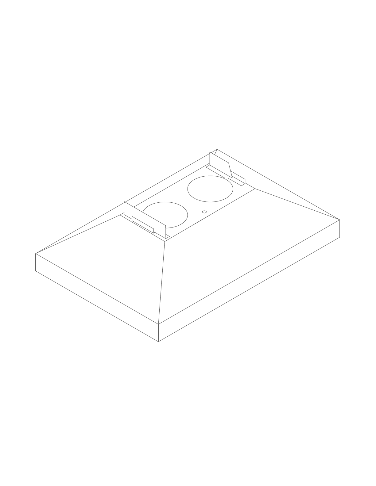
Flush Mount Installation Details:
CABINET: Be sure cabinet bottom is level, side to
side and front to rear.
For the “SD” units prepare cabinet by cutting an
8” x 8” hole in bottom, 3/4” from wall and on
Center line.
For the “PS1” units prepare the cabinet by
cutting a 10 3/8” (D) x 20 1/4” (W) hole in the
bottom, 1/2” from wall and center line.
Shelves and top to be cut to clear 7” round pipe.
Also, cut holes for electrical wires.
4-
6"
3/
"
4
1/
7/8"
1-
NOTE: Bolts, washers and nuts supplied.
Remove the Drawer before positioning the hood
under the cabinet. *See next page on how to
17-1/4"
remove.
Position hood against cabinet bottom and against
wall. Mark the underside of cabinet through
1
-
3
each key-hole for location of each bolt hole.
Drill 3/16” holes through cabinet bottom. Insert
bolts with small washer under head of bolt
through cabinet bottom from inside the cabinet.
Again, position hood under cabinet with bolts
"
2
/
1
1/2"
”
4
/
"
3
-
1
/
1
1
-
4
1
6
0
-
1
/
4
7"
8
"
through key-holes. Starting with front key-holes,
place large washer on bolt, attach the wing-nut to
6"
bolt, secure both front wing-nuts. Push hood
back against wall, secure large washer and the
wing-nuts on rear bolts.
Re-install the pull out drawer.
Connect duct and tape all joints.
Replace Filters
21-3/4"
ELECTRICAL:
Stub enough wire into cabinet to reach in front of vent pipe.
Remove Black Tape that holds dampers in closed position.
Enter the cabinet 3 1/4” left of center for (SD unit) or 2 1/4” for the (PS1 unit).
Remove splice box cover before mounting the hood.
After hood is mounted attach house wires to leads in hood.
Secure locknut to conduit and check wiring for compliance with all local codes.
Replace splice box cover.
Standard Duct size is 7” Round. Increase CFM by increasing duct size:
7” to 8” transitions to increase CFM by 20%. (Available on PS1 models only)
1
4"
7"
1
3-
2"
/
1
/
4
"
-
1
-
7/8"
1
/
4
"
"
4
/
1
-
4
"
0
2
”
4
/
6"
3
-
1
/
1
4-
2"
/
,
"
30
"
8
/
1
1
1
-
3
/
4
9
4
,
"
36
1
1
-
9
-
1
/
8
"
5"
3
,
"
0
3
"
-
1
/
8
"
"
8
4
or
2"
3
/
4
"
"
2
4
r
o
"
6
Models are indicated with an
8 for 8” duct.
Example: G3036PS1-8 or 3036PS1-8
 Loading...