

Imperial DG950, DG950R Users Manual

2
2
2
3
3
3
3
4
5
5
9
10
10
10
10
11
11
12
13
13
13
13
13
13
13
14
14
14
14
14
15
15
15
15
15
16
16
17
18
19
22
28
28
29
29
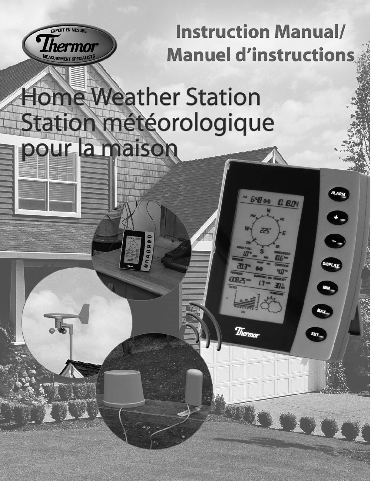
Home Weather Station (HWS)
Instruction Manual
Table of Contents
1. Introduction
2. Safety Notes
3. Weather Station Function and Features
Features of the Home Monitor
Features of the Thermometer-Transmitter Sensor
Features of the Wind Sensor
Features of the Rain Sensor
4. Components of your Home Weather Station
5. Setting up the Weather Station
A.Mounting
B.Powering up your HWS (for the first time)
C.Changing the transmitter batteries
D.Connecting the Sensors
6. Wireless Tr ansmission
7. LCDOverview
8. LCDBreakdown
9. Optimum Viewing Angle
10. Button Breakdown
11. Setting the Home Monitor
Time
Date
Wind Speed
Temperature
Pressure
Rainfall
12. Setting the Alarm
Alarm Clock
Indoor T emperatur e Alarm
Outdoor T emper ature Alarm
13. Turning off the Alarm(s)
14. Minimum or Maximum Memory Recall
15. Minimum or Maximum Memory Reset
16. Rainfall Measurement Reset
17. Rain Gauge Maintenance
18. Trend Chart
19. Weather Forecasting
20. Barometric Pressure
Elevation of Major Cities in Canada
Elevation of Major Cities in the US
21. Barometric Pressure Conversions
22. Troubleshooting
23. Product Specifications
24. Warranty
25. Resources to Look At
26. FCC Information

This instruction manual is part of this product and should be kept in a safe place for future reference.It contains
important information on setup and operation.
1. INTRODUCTION
Thank you for purchasing Thermor’s Wireless Home Weather Station (HWS). Developed with state of the art
technology and digital electronics,this device provides instant readouts of the weather conditions around you.
To understand how to properly install and program your weather station,please read this instruction manual
carefully and keep it in a safe place.
The Home Weather Station and its accuracy is meant for personal use. This information should not be used for
scientific purposes.
2.SAFETY NOTES
• Damage caused by failure to comply with this instruction manual will invalidate any warranty! The manufacturer
and supplier will not be held liable for any damages due to failure to comply with this product!
• In case of harm or damage to a person or property caused by improper handling or failure to comply with this
instruction manual,the manufacturer and supplier cannot be held liable.
• For reason of safety and operation,alteration to this device is strictly prohibited.
• To operate the weather station,use only supplied adapter and batteries of the recommended type.
• Do not leave discharged batteries in the device as these may corrode and release chemicals that may damage
the unit.
• Inserting batteries in an incorrect polarity will cause damage to this product.
• Do not dispose of new or used batteries in a fire as the may explode or release dangerous chemicals into the
environment.
• This product is not a toy;keep out of the reach of children.
• This product is not to be used for medical purposes or for public information.
• Any modification or alteration to this product is strictly prohibited without the manufacturer’s authorization and
may prohibit the user’s further use to this product.
3.WEATHER STATION FUNCTION AND FEATURES
The home monitor measures the indoor environment of its surrounding area (temperature, humidity and
atmospheric pressure) and receives weather data from the following three outdoor sensors:
1) Thermometer-T ransmitter Sensor
2) Wind Sensor (speed and direction)
3) Rain Gauge Sensor (cumulative rainfall)
The data from the outdoor sensors is transmitted every 128 seconds to bring you the latest weather information
which is displayed on the home monitor’s LCD (updating the information faster is prohibited by FCC criteria and
would drastically reduce battery life). The outdoor thermometer-transmitter sensor is the main data
communication unit. The thermometer-transmitter connects to the wind and rain sensors via insulated cables,
whereby power and weather information is transferred. The collected data is then transmitted by the
thermometer-transmitter back to the home monitor. Weather data is sent from the thermometer-transmitter
sensor by wireless transmission -- 433MHz (up to 100 meters in open space).
2
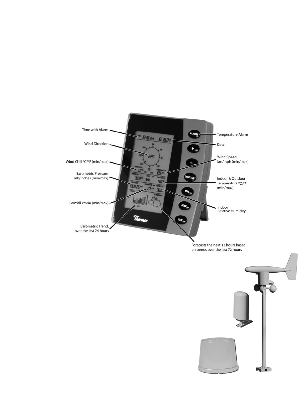
Features of the Home Monitor
• Displays time and date with alarm clock
• Displays weather conditions and records minimum and maximum values
• Displays indoor and outdoor temperature in Fahrenheit (°F) or Celsius (°C) -- user selectable
• Displays indoor relative humidity (RH%)
• Displays barometric (air) pressure reading in inches of mercury (inHg) or millibars (mb) -- user selectable
• Displays cumulative rainfall data since last reset in inches (in) or centimeters (cm) – user selectable
• Displays wind speed in miles per hour (mph) or kilometers per hour (km) -- user selectable
• Wind direction display with LCD compass as well as numerical (e.g.225°) and abbreviated characters (e.g.NE)
• Wind chill temperature display
• Displays weather forecast using weather icons (sunny,partly cloudy,cloudy or rainy)
• Barometric trend chart in inches of mercury (inHg) or millibars (mb) -- user selectable
• Indoor and outdoor temperature alarms that are set by the user (rising temperature alarm only)
Features of the Thermometer-Transmitter Sensor
The thermometer-transmitter sensor measures the outdoor temperature. It also collects
readings from the rain gauge and wind sensor,then transmits the data to the home monitor
via wireless 433MHz transmission. The transmitter uses two AA batteries (not included).
Features of the Wind Sensor
The wind sensor measures wind speed and wind direction and sends
the data to the thermometer-transmitter sensor,which in turn
transmits the data to the home monitor.Operating power is taken
from the thermometer-transmitter sensor by cable connection.
Features of the Rain Sensor
The Rain Sensor measures cumulative rainfall and sends the data to the
thermometer-transmitter sensor via cable connection,which is then
transmitted back to the home monitor. The cable connection also
supplies operating power from the thermometer-transmitter sensor to
the Rain Sensor.
Thermometer-
Transmitter
Sensor
Rain Sensor
Wind
Sensor
3
4.COMPONENTS OF YOUR HOME WEATHER STATION
Before setting up,carefully unpack the contents onto a table or flat surface and check that the following pieces are
included in the package:
4
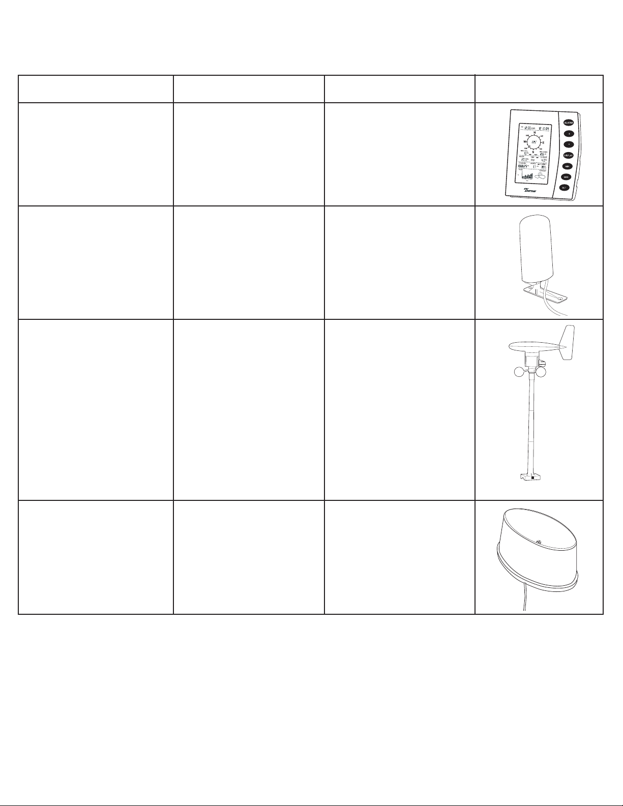
Item Components Fittings Illustration
Home Monitor
Thermometer & Transmitter
Sensor
Wind Sensor
Rain Sensor
• Main unit
• Main unit
• Rain protection cover
• Base bracket
• Main unit with wind vane
• 30ft cable (9 m) (already
attached to the main unit)
• Mast
• Base bracket
• Main unit
• 30ft cable (9 m) (already
attached to the main unit)
• AC/DC 120V power
• Adapter – primary use
(included)
NOTE: 3 x AA batteries
should be used for back-up
purposes only.
• 2 x 1.75”wall mounting
screws
• Plastic anchors for screws
*requires 2 x AAbatteries
(Recommendation: use lithium
AA batteries (view “Battery
Installation”section)
• 2 x U–bolts to secure to a
mast
• 8 x washers
• 4 x nuts
• 8 x 0.25”screws (to fix
mast to main unit and
base bracket)
• 4 x 2.75”screws (to fix
base bracket to a flat
surface)
• 2 x 2.75”screws (to fix rain
sensor to a flat surface)
5.SETTING UP THE WEATHER STATION
CAUTION: Great care must be taken when mounting the Home Weather Station components.The
manufacturer/supplier can not be held liable for personal or property damage when setting up the components.
Please use caution when choosing a mounting point.
A.Mounting
IMPORTANT: Prior to drilling mounting holes and permanently affixing any of the units,please ensure the
following points are considered:
1.Cable lengths of the units meet with your distance requirements at mounting points.
2.Signal from the thermometer-transmitter sensor can be received by the Home Monitor at mounting point.
3.Make sure the transmitter is easily accessible. You will have to periodically replace batteries. Mount it as close to
the ground as possible.
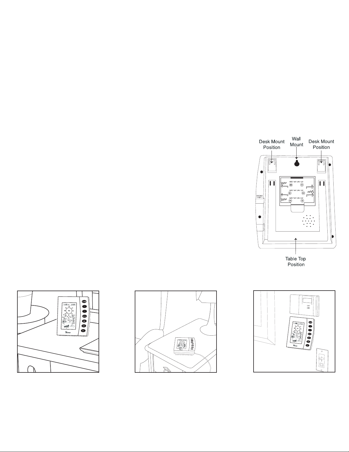
Mounting
Home Monitor
With three retractable legs at the back of the Home Monitor,the unit can be placed
onto any flat surface or mounted on a wall by using a nail or screw (not provided).
• To prevent improper temperature measurements,make sure that the Home
Monitor is not placed in direct sunlight, or placed in an area with drafts caused by
heaters or air conditioners.
• Do not mount the home monitor on a wall which has metal heat/air conditioning
ductwork or high voltage wiring in the wall behind the station,it may interfere
with its ability to receive data from the transmitter.
• For proper data transmission,do not mount the home monitor closer than 5 feet
from a computer,fluorescent lights or other electrical appliances. Such devices
dramatically decrease signal reception,and in some cases,prevent all signals from,
reaching the thermometer-transmitter sensor.
• If the main unit is in an area of transmission interference (e.g.on or near concrete
walls,home appliances,computers or metal objects) the distance of transmission
will be drastically reduced or non-existent.
5
T able Top Position
Desk Mount Position
Wall Mount
Mounting
Wind Sensor
First,choose whether the wind sensor will be mounted vertically or
horizontally (on a mast). Make sure that you position the wind sensor
in a free,open area that is not protected by objects,which may distort
or interfere with the wind (e.g.large buildings,trees,chimney,etc.).
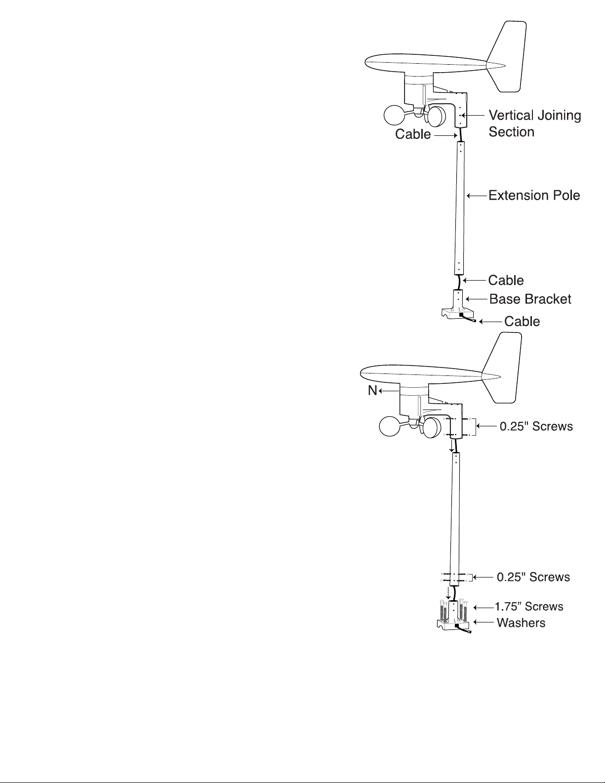
Cable Preparation for Vertical Mounting
1.Run the cable that is already fastened to the wind sensor through
the vertical joining section (see right).
2.Run the cable through the extension pole but do not secure the
pole to any sections yet.
3.Now run the cable through the top of the base-bracket and the
through the small rectangular section found on one side of the
base-bracket.
NOTE: Make sure that you completely pull the cable through the
wind sensors extension pole and base-bracket to reduce the
amount of slack on the cord.
Vertical mount
1.Make sure that the wind vane can rotate freely before fastening
the unit permanently into position.
2.Insert one end of the pole extension provided into the basebracket.
3.Secure the connection point of the pole extension and basebracket using the 0.25”metal screws provided to prevent rotation
at the joining point.(Use 4 x 0.25”screws to ensure stability).
4.Insert the vertical joining section on the bottom of the wind
sensor into the top of the pole extension. (Ensure that you pull
all cable slack through the side of the base-bracket to prevent
creasing or cutting the cable).
5.Secure the wind sensor to the mounting pole using the 0.25”
screws provided to make sure that the pole connection does not
rotate.(Use 4 x 0.25”screws to ensure stability).
IMPORTANT:For accurate readings,it is important to mount the
wind sensor so that the directional prints on the casing are facing
their respective directions (e.g.“N”on the casing is facing north).
If necessary,use a standard compass to determine north.
6. .Using 4 x 1.75”screws provided,secure the wind sensors basebracket to a flat surface.
NOTE: Make sure that when you are securing the base bracket with
the 1.75“ screws,you are aware of the cable.Prevent driving a screw
through a cable!
6
VERTICAL
MOUNT
Horizontal Mounting
Cable Preparation for Horizontal Mounting
1.Run the cable that is already fastened to the wind sensor through the horizontal joining section (see below).
2.Run the cable through the extension pole but do not secure the pole to any sections yet.
3.Now run the cable through the top of the base-bracket and then through the small rectangular section found
on one side of the base-bracket.
NOTE: Make sure that you completely pull the cable through the wind sensor's extension pole and base-bracket
to reduce the amount of slack on the cord.
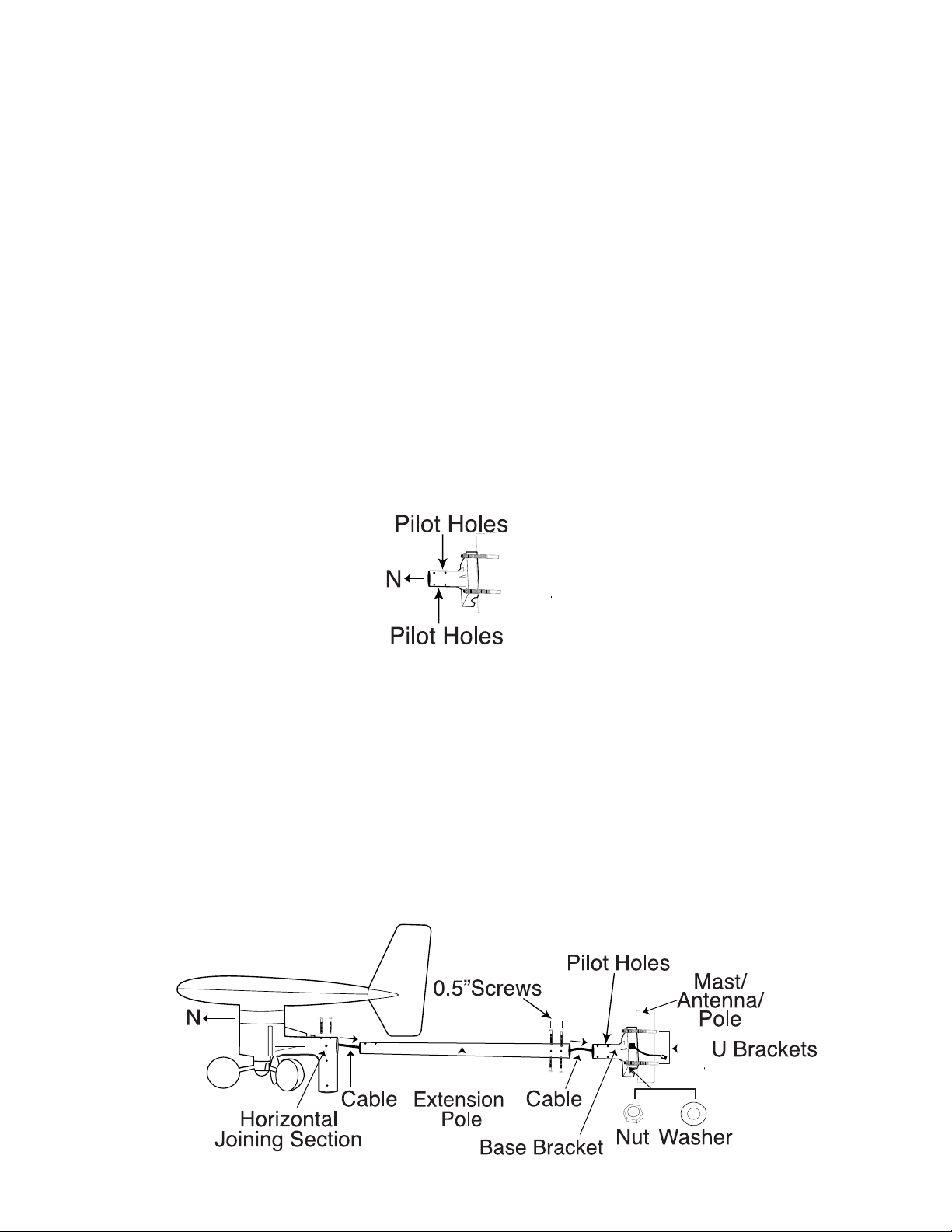
Horizontal mount – using a mast/antenna/pole
NOTE:It is not recommended to secure the wind sensor horizontally from a wall or chimney because doing so will
interrupt the flow of wind from at least one direction.
MOUNT WITH “N“ FACING NORTH:
For accurate readings,it is important to mount the wind sensor so that the directional prints on the casing are
facing their respective directions (e.g.“N”on the casing is facing north). If necessar y,use a standard compass to
determine north.
1.Make sure that the wind vane can rotate freely before fastening the unit permanently.
2.Using 2 x U-bolts,4 x nuts and 4 x washers,secure the base-bracket of the wind sensor to a stable
mast/antenna/pole. (M asts made of lead or other materials will cause faulty readings).
IMPORTANT:Make sure that the pole insert of the base-bracket is facing north (N) and
the pilot holes are on the top AND bottom.
3.Use the pole extension provided to distance the wind sensor from the stable mast/antenna/pole. Insert one end
of the pole extension into the base-bracket.
4.Secure the connection point of the pole extension and base-bracket using the 0.25”screws provided to prevent
rotation at joining point. (Use 4 x 0.25”screws to ensure stability).
5.Insert the pole extension into the horizontal joining section.(Ensure that you pull all cable slack through the side
of the base-bracket to prevent creasing or cutting the cable).
6.Secure the horizontal joining section to the mounting pole using the 0.5”screws provided to make sure that the
pole connection does not rotate.
HORIZONTAL MOUNT
7
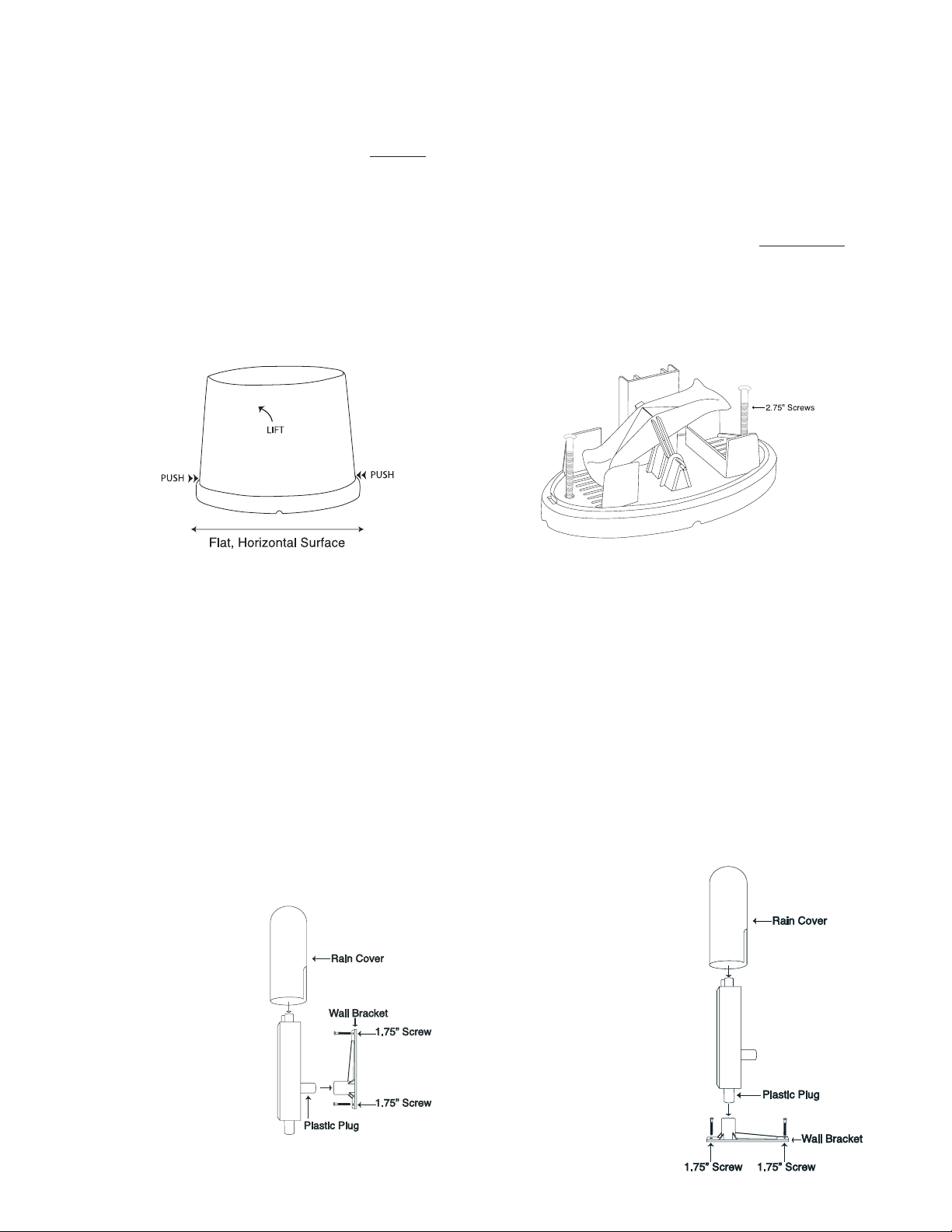
Mounting
Rain Sensor
It is important that the rain sensor has the correct exposure to ensure accurate rainfall measurements. Place the rain
sensor as far away as possible from tall buildings,trees or other obstructions. It is suggested that the rain sensor
should be no closer to tall objects or obstructions than twice the height of the object compared to the sensor.
However, low bushes,fences or walls in the vicinit
y of the gauge are not objectionable,as these usually help break
up the force of the wind during stormy weather conditions.
NOTE: I t is recommended by Environment Canada that you mount the rain sensor 18“ (46 cm) above ground or
surface to prevent water from splashing off the ground/surface,into your rain gauge.
1. In order for the rain sensor to work properly,you MUST place the rain sensor on a flat,hor
iz
ontal surface.
2.Remove the rain gauge lid by pushing on the tabs at either end,and pulling it upwards off the base.
3.Test that water can flow freely between the base of the rain sensor and horizontal mounting surface – pour clear
water over the water collection device and view the flow.
4.Using 2 x 2.75”screws,secure the base of the rain gauge to the flat,horizontal surface.
Mounting
Thermometer-Transmitter Sensor
It's recommended to mount the thermometer-transmitter sensor on a lower level wall on your home.
Wall Mount
1.Affix the wall bracket onto a desired wall using the 1.75”screws provided.
2.Insert the plastic plug on the back of the thermometer-transmitter sensor into the wall bracket socket.
Vertical Mount
1.Affix the wall bracket onto a flat,horizontal surface using the 1.75”screws provided.
2.Plug in the thermometer-transmitter using the plastic plug found on the bottom of the sensor into the wall
bracket socket. DO NOT mount the thermometer-transmitter sensor upside down.
8
WALL MOUNT
VERTICAL MOUNT
 Loading...