

Page 1
Powered Liner—C2000
Installation Instructions
&
LNR/9.17
Warranty Information
425 Apollo Street
Brea, CA 92821
www.imperialhoods.com
(800) 851-4192
DO NOT THROW AWAY,
PROPERTY OF THE HOME OWNER!
Page 2
Imperial Cal Products, Inc.
Any cosmetic defects must be reported to us prior to installation.
Once this hood is installed, ICP will NOT accept any responsibility
for any cosmetic blemishes, scratches or dents in the Canopy.
Save all original packaging if you wish to return for any reason!
FIRST:
Check your local building and electrical codes.
WARNING:
To reduce the risk of fire or electrical shock, Do Not use any two speed motor units with a Solid
State control devise.
CAUTION:
To reduce the risk of fire or personal injury and to properly exhaust air, be sure to duct air to the
outside. DO NOT vent exhaust air into spaces within wall, attics, ceilings, crawl spaces or
garages. When venting to the outside make duct run as short and straight as possible.
Avoid using elbows if at all possible as this will reduce your performance. Every elbow will
decrease the performance and we will not guarantee the effectiveness of the range hood.
No Performance Warranty when used above BBQ Style Grills.
DO NOT use duct pipe smaller than the outlet duct opening on the hood, this will reduce
performance and void the warranty. DO NOT use flex ducting. Also, use either a Roof Cap or
Wall Cap to end run. Be sure that all joints are taped securely in place. It is essential to have the
proper distance between the bottom of the range hood and the cooking surface below. In most
cases the cooking appliance manufacturers specifications will establish the fire safe minimum
distance required, although there are other factors to consider:
Local Building Codes
Cross directional air movements ie: open windows, air conditioning/heating outlets, cooling
fans, etc.
Overall size of the cooking appliance and surrounding countertop surfaces.
Range hood model selected.
For best performance distance between cooking surface and the bottom of the hood is 30” and
36”. Check local codes and appliance specifications. Keep in mind, increasing the distance will
decrease the performance.
THERMOSTAT: PS or BP Units ONLY. When cooking surface reaches 130 degrees, the unit will
automatically turn ON to the highest setting and won’t be able to be turned off until the area has
cooled down. For safety, it’s best to have unit on while cooking. (This thermostat will NOT prevent
fires. Fires are most often cause by excessive grease build up.)
TWIN UNITS ONLY - Transitioning two pipes into one is NOT recommended. CFMs are reduced
by 25% and the Performance Warranty will be void.
DISCLAIMER
Imperial assumes no liability regarding the improper installation or misapplication of its products. It
is the installer’s responsibility to check for proper installation. Under no circumstances will Imperial
be liable for any labor charged or travel time incurred installation of its products. Damage caused
by improper installation is the installers responsibility and Imperial assumes no liability.
Read Before Starting Installation!
Inspect your range hood prior to installing!
Page 3
Powered Liners Installation Detail:
MODEL MESH FILTERS MODEL BAFFLE FILTERS
C2000SD2 (SD2-NV) C2000BPB
C2000SD4 (SD4-12) C2000PSB
C2000BP (BP1-duct is offset to the left) C2000BP1-TW / TWB (requires 2 duct pipes)
C2000PS C2000PS1-TW / TWB (requires 2 duct pipes)
C2000PS-IS22 (Island Application)
C2000PS-IS28 (Island Application)
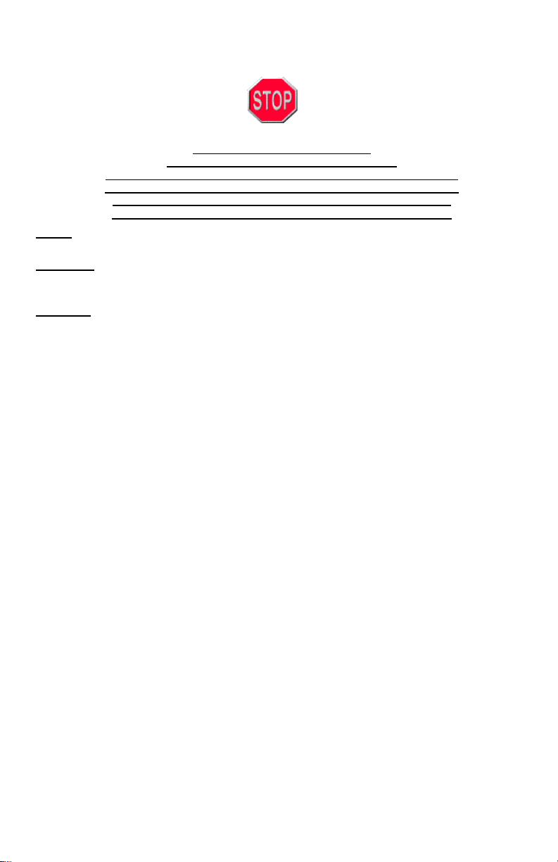
1. Line up powered liner to underside
of cabinet or canopy. If unable to
drill directly into cabinet or canopy,
use 4” x 11-1/4” x 3/4” wood blocks
(Figure 1) on the inside of canopy, left
and right side and secure with
screws.
2. Remove Filters of powered liner.
Remove the BLACK tape that holds
the damper blades closed.
(Figure 2) (It
is NOT recommended to use two (2)
dampers during installation. You have the option to use an external damper or use the
existing damper already on our unit.)
3. Raise and position powered liner so that the bottom is level with
cabinet and screw through holes on either side of liner. DO NOT
use Motor Mounts as Gripping Points. The duct pipe or pipes
should slip into the Automatic Seal Vent Collar. Additional Duct
Tape can be use if needed.
4. If required, additional mounting at the rear of the unit: Locate wall
studs, drill holes through back of insert to hit studs and attach the
liner to the wall with screws.
5. Island and Peninsula liners should be mounted in the same way
except there will be no rear wall mount.
6. Bring conduit down 4” past the bottom of the liner. NOTE: Top box
for the C2000BP1 shows vent opening Off-Set to the left (facing the hood). The lower
box will be the same size as the other models.
7. Remove junction box cover from C2000. (Be sure to comply with all local electrical and
safety codes.) Units are to be hard wired
. It is not recommended to add a powercord. Adding a power cord can loosen existing wires inside junction box causing
electrical failure.
8. Hook up electrical wires and secure inside junction box. Replace junction box cover.
Install lights and replace filters. For Baffle filters installation, see baffle installation
page enclosed.
TWIN UNITS ONLY—Transitioning two pipes into one is NOT recommended. CFMs are
reduced by 25% and will VOID the Performance Warranty.
DUCT SIZE INDICATOR - Our standard units have a 7” Round which can be transitioned to
8” Round or 10” Round to increase CFM.
See example below:
C2000PS-8 = 8” Round Transition
C2000PS-K = 10” Round Transition
(FIGURE 1)
(FIGURE 2)
Page 4
Powered Liners Installation Detail Continued:
Re-Circulating, (Non-Vented) Series: C2000SD2-NV
For use when unable to terminate exhaust ducting to outside the structure.
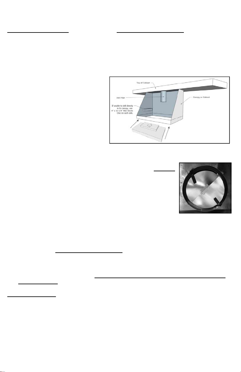
Figure 1:
Figure one shows the included elbow
transition from 7” diameter round to 3
1/4” x 10” rectangular. This transition is
used to return the filtered air back to
inside the kitchen either through the
canopy face of if applicable the soffit
above. The customer must provide
the appropriate length of straight
7” round ducting that connects the
hood exhaust to the elbow
transition.
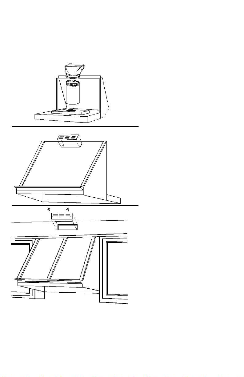
Figure 2
Figure two shows a typical air exit
terminating through the canopy face. A
customer supplied, decorative 4” x 10”
register cover face plate should be
used to finish off the cut out opening.
Figure 3
Figure three shows a typical air exit
terminating through the soffit face
directly above the hood canopy.
Again the customer must provide a
4” x 10” register face plate.
Figure 1
Not Included
Canopy Exit
Figure 2
Soffit Exit
Figure 3
View from rear of the canopy.
Included
4” x 10” Cover
Face Plate
4” x 10” Cover
Face Plate
NOTE: The C2000 NV Unit comes supplied with charcoal filters that will accumulate
the cooking grease and over time decrease the hoods performance. The amount and
style of cooking will dictate how often the filters should be replaced. This type of filter
is designed for replacement only. Contact Imperial to purchase proper replacement
filters.
Page 5

Imperial Cal Products, Inc.
To order replace parts or schedule service please call our office at (800) 851-4192
or use our website… www.imperialhoods.com.
PARTS:
When ordering Parts we need the following information:
Model Number (not serial number) found on UL label inside hood.
Exact dimensions (in the case of filters)
You can find the model number on the inside of your hood on our UL label. There will be a
several model numbers listed, your model number should have a colored dot or mark next to
it to indicate the exact model you have.
In the case of Filters, we will need the exact dimensions of the filter needed.
Indicate which side has the pull tabs on it. Filters are not a warranty replacement part. With
care your filters should last many years.
Payment on Parts is handled one of three ways: PrePaid (you send a check prior to our
Shipping), call with credit card information, VISA or MasterCard, COD or Cash if you decide
to “Will Call”. Our Will Call hours are 8:30 to 3:30, Monday through Friday.
SERVICE:
When calling in for Service we need the following information:
Model Number (not serial number)
Proof of Purchase
Name of company you purchased the hood through.
Name & Phone number of the person to contact to set up the service call.
Full address of the location where service is to be done.
Warranty is Seven Years, Parts and Labor.
Page 6

Maintenance & Warranty Information
RANGE HOOD CLEANING—When cleaning a painted hood, wash it with mild, soapy
water ONLY! Wipe the hood thoroughly with clean water and dry with soft cloth. When
cleaning Stainless Steel use a cleaner specifically for Stainless Steel. Always rub with the
grain using non-abrasive cleaning materials. AVOID detergents, disinfectants or cleaning
products in aerosol cans. NEVER use abrasive scouring powders on your hood! Some
cleaning chemicals may damage the hood finish!
BAFFLE FILTER CLEANING—To remove Baffle Filters, remove center panel by pulling
panel toward the front of the hood, lift up to remove. Move filters to the center of the hood,
pull baffle towards the front of the hood and lift out. To remove grease tray, slide tray to the
top of the hood and lift out. Grease will accumulate in grease tray. Clean with hot water and
polish with stainless steel cleaner.
SLIM BAFFLE & ALUMINUM MESH FILTER CLEANING
Clean filters often for the best performance. How often depends on cooking style. Use hot
water and a degreaser to clean. May be used in the dishwasher through the RINSE
cycle ONLY. Some detergents may discolor filters. For Slim Baffles polish baffle side
with stainless steel cleaner.
LIGHTING
38 or 50 Watt Halogen Flood (Par 20—Medium Base) OR 7 Watt or 9.5 Watt LED
Flood. LED MUST be the equivalent of the 50 Watt Halogen-Par 20 Dimmable)
LED Bulbs will protrude approx. 1/4” to 1/2” down from panel.
Warning: Do not use any bulbs that are not instructed by manufacturer. Do not use
Halogen bulbs in sockets not intended for their use! They are to be used only in the Front
Light and Center Light Panels.
Your Imperial Warranty: Proof of original purchase date is needed to obtain
service under warranty.
Deluxe Units: Seven Year Limited Warranty, Parts and Labor in the Continental
USA. Parts only outside the United States.
For seven years from date of original purchase, we will provide parts and service labor in
your home to repair or replace any part of the hood that fails due to a manufacturing defect.
Call for service at (800) 851-4192
NOTE: Service companies will perform Warranty Service, Monday through Friday from
7 a.m.—4: p.m. The service company will call and schedule a date and time with a 4 hour
window. If the service company arrives at your location, during the scheduled date and
time, and no one is home, you will be charged a trip charge by the service company for a
return service call.
ITEMS IMPERIAL WILL NOT PAY FOR
1. Service calls to correct the installation of your appliance, to instruct you how to use your
appliance, to replace or repair house fuses or the correct housing wiring or plumbing.
2. Service calls to repair or replace appliance light bulbs or filters.
3. Repairs when your appliance is used for other than normal, single-family household use.
4. Damage resulting from accident, alteration, misuse, abuse, fire, flood, acts of God, improper
installation, installation not in accordance with electrical or plumbing codes.
5. Replacement parts or repair costs for units operated outside the United States.
6. Pickup and delivery. This appliance is designed to be repaired in the home.
7. Repairs to parts or systems resulting from unauthorized modification made to the appliance.
8. Expenses for travel and transportation for product service in remote locations.
9. The removal and reinstallation of your appliance if it is installed in an inaccessible location or
is not installed in accordance the published installation instructions.
10. Replacement parts or repair labor costs when the appliance is used in a country other than
the country in which it was purchased.
Page 7

SAFETY INSTRUCTIONS
Read and Save These Instructions
Warning: To reduce the risk of fire, electrical shock or injury to persons, observe the
following:
A. Use this unit only in the manner intended by the manufacturer. If you have any questions,
contact the manufacturer. Before servicing or cleaning unit, switch power off at service
panel and lock Service Disconnecting Means to prevent power from being switched on
accidentally. When the Service Disconnecting Means cannot be locked, securely fasten a
prominent warning device, such as a tag, to the service panel.
Warning: To reduce the risk of a range top grease fire:
A. Never leave surface units unattended at high settings. Boil-overs cause smoking and
greasy spillovers that may ignite. Heat oils slowly on low or medium settings.
B. Always turn hood ON when cooking at high heat or when Flambéing foods (i.e. Crepes
Suzette, Cherries Jubilee, Peppercorn Beef Flambé).
C. Clean ventilating fans frequently. Grease should not be allowed to accumulate on fans or
filters.
D. Use proper pan size. Always use cookware appropriate for the size of the surface
element.
Warning: To reduce the risk of injury to persons in the event of a range top
grease fire, observe the following:
A. SMOTHER FLAMES with a close-fitting lid, cookie sheet or metal tray, then turn off the
burner. BE CAREFUL TO PREVENT BURNS. If flames do not go out immediately,
EVACUATE AND CALL THE FIRE DEPARTMENT.
B. NEVER PICK UP A FLAMING PAN - you may be badly burned.
C. DO NOT USE WATER, including wet dishcloths or towels, violent steam explosion will
result.
D. Use an extinguisher ONLY if:
You know you have a Class ABC extinguisher and you already Know how to use it.
The fire is small and contained in the area where it started.
The fire department is being called.
You can fight the fire with your back to an exit.
Warning: To reduce the risk of fire, electrical shock or injury to persons, observe the
following:
A. Installation work and electrical wiring must be done by a qualified person or persons in
accordance with all applicable codes and standards, including fire-rated construction.
B. Sufficient air is needed for proper combustion and exhausting of gases through the flue of
fuel burning equipment to prevent back drafting. Follow the heating equipment manu-
facturer’s guideline and safety standards such as those published by the National Fire
Protection Association (NFPA), and the American society for Heating, Refrigeration & Air
conditioning Engineers (ASHRAE), and the local code authorities.
C. When cutting or drilling into a wall or ceiling, do not damage electrical wiring and other
hidden
utilities.
D. Ducted fans must always be vented to the outdoors.
Warning: To reduce risk of fire, use only Smooth Metal Ducting!
Page 8

Liner alimenté—C2000
Instructions d'installation
&
Informations sur la garantie
425 Rue Apollo
Brea CA 92821
www.imperialhoods.com
(800) 851-4192
PROPRIÉTÉ DU PROPRIÉTAIRE DE LA MAISON,
NE PAS JETER !
Page 9

Impériale Cal Products, Inc.
Lire avant de commencer l'Installation !
Inspecter avant d'installer votre hotte de cuisinière !
Les défauts cosmétiques doivent nous être signalés avant l'installation.
Une fois cette hotte est installée, ICP n'acceptera aucune responsabilité
pour toute les imperfections cosmétiques, rayures ou bosses dans la canopée.
registrer tous les emballages d'origine si vous voulez
retourner pour n'importe quelle raison !
TOUT D'ABORD :
Vérifiez vos locales de construction et les codes de l'électricité.
AVERTISSEMENT :
Pour réduire le risque d'incendie ou d'électrocution, ne pas utiliser n'importe quelle unité
de moteur à deux vitesses avec un Solid State devise de contrôle.
MISE EN GARDE :
Pour réduire le risque d'incendie ou de lésions corporelles et pour bien évacuer l'air,
n'oubliez pas d'évacuer l'air vers l'extérieur. N'évacuez pas l'air dans des espaces dans le
mur, les greniers, les plafonds, les espaces confinés ou les garages. Lorsque la décharge
à l'extérieur faire conduit tourner aussi court et aussi droit que possible. Évitez d'utiliser
des coudes si possible. Si les coudes sont utilisés, nous recommandons que le premier
coude est 24 "d'ouverture sur le capot (minimum de 12 po) et au moins 24" entre elle et le
coude du prochain. Nous ne recommandons vivement aucuns plus puis exécutez deux
coudes de 90 degrés dans n'importe quel canal. Aucune garantie de Performance lors
de l'utilisation au-dessus des grilles de Style BBQ.
N'utilisez pas conduit plus petite que la sortie du conduit d'ouverture sur le capot, cela
réduira les performances et annuler la garantie. N'utilisez pas de conduits flexibles. Aussi,
utilisez soit un capuchon de toit ou de mur à la course de fin. N'oubliez pas que tous les
joints sont scellés
solidement en place. Il est essentiel d'avoir la bonne distance entre le bas de la hotte et la
table de cuisson ci-dessous. Dans la plupart des cas, les spécifications de fabricant
appareil cuisson établira la distance minimale sécuritaire de feu requise, bien qu'il existe
d'autres facteurs à considérer : LocalBâtimentCodes Traverser c'est à dire les
mouvements d'air directionnel : ouvrir les fenêtres, prises d'air conditionné/chauffage,
refroidissement, ventilateurs, etc.. Taille globale de l'appareil de cuisson et les surfaces
environnantes de comptoir. Hotte d'aspiration modèle sélectionné.
Pour la meilleure distance de performance entre la surface et le fond de la hotte de
cuisine est 30 "et 36". Consulter les codes locaux et spécifications de l'appareil. Gardez à
l'esprit, augmente la distance diminue les performances.
TWIN unités seulement- Phase de transition de deux tuyaux en un seul n'est pas
recommandé. SSFC est réduits de 25 % et la garantie de Performance seront annulée.
En-
Page 10

Détail d'Installation Liners alimenté :
MODEL MESH FILTERS MODEL BAFFLE FILTERS
C2000SD2 (SD2-NV) C2000BPB
C2000SD4 (SD4-12) C2000PSB
C2000BP (BP1-duct is offset to the left) C2000BP1-TW / TWB (requires 2 duct pipes)
C2000PS C2000PS1-TW / TWB (requires 2 duct pipes)
C2000PS-IS22 (Island Application)
C2000PS-IS28 (Island Application)
1 Line up doublure alimenté pour dessous d’armoire ou de la verrière. Si incapable de
percer directement dans l’armoire ou
verrière, utilisez les blocs de bois 4 "x
11-1/4" x 3/4"
(Figure 1) à l’intérieur de
la verrière, gauche et droite côté
et fixer avec les vis.
2
Supprimer des filtres de doublure
sous tension. Supprimer le
ruban adhésif qui maintient les
lames clapet fermé.
pas recommandé d’utiliser deux 2
amortisseurs lors de l’installation.
Vous avez la possibilité d’utiliser un clapet externe ou utiliser le clapet existant déjà sur
notre unité.)
3
Relance et position propulsé doublure afin que le fond est à niveau avec armoire et vis
dans les trous de chaque côté de la membrane. Ne pas utiliser
des supports moteur comme Points de préhension. Le
conduit ou les tuyaux doit glisser dans le collet de l’évent
automatique joint. Supplémentaires du ruban adhésif peut
être utilisé si nécessaire.
4
Si nécessaire, supplémentaires de montage à l’arrière de
l’appareil : localiser les montants du mur, percez les trous arrière
de puissance suffisante pour frapper les goujons et fixez la toile
au mur avec des vis.
5
Doublures de l’île et la péninsule doivent être montés de la même
manière, sauf qu’il n’y aura pas de montage paroi arrière.
6
Conduit Bring down 4" passé le fond de la cocotte. Remarque : Top box pour le
C2000BP1 montre ouverture décalée vers la gauche (en face de la hotte). La
zone inférieure sera la même taille que les autres modèles.
7
Supprimer la boîte de jonction couvercle de C2000. (Veillez à respecter tous les codes
de sécurité et les locaux d’électricité).
pas recommandé d’ajouter un cordon d’alimentation. Ajout d’un cordon
d’alimentation peut se dégager des fils existants à l’intérieur de la boîte
de jonction, causant des pannes électriques.
8 Boîte de jonction
Replacer le couvercle de la boîte de jonction. Installer des lumières et remplacer les
filtres.
Pour déflecteur installation des filtres, voir page installation d’un
crochet vers le haut de fils électriques et sécurisé à l’intérieur.
déflecteur.
Deux unités seulement — Transition deux tuyaux en une seule est pas recommandé.
SSFC sont réduits de 25 % et sera vide la garantie Performance.
Indicateur de taille de conduit -Nos unités standards ont un 7" rond qui peuvent être
passés à 8" rond ou 10" rond pour augmenter pi3/min.
Noir
(Figure 2) (Il n’est
(FIGURE 1)
(FIGURE 2)
Unités doivent être câblés dur. Il n’est
Page 11

Détail Installation Liners propulsé a continué :
Série recyclée, (Non ventilé): C2000SD2-NV
Pour être incapable de clore la sécheuse au dehors de la structure.
Figure 1
Not Included
Canopy Exit
Figure 2
Soffit Exit
Figure 3
View from rear of the canopy.
Included
4” x 10” Cover
Face Plate
4” x 10” Cover
Face Plate
La figure 1 :
La figure montre la transition de coude
inclus de 7 "diamètre rond de 3 1/4 « x
10 » rectangulaire. Cette transition est
utilisée pour retourner la filtrée à l'air à
l'intérieur de la cuisine, soit par le biais
de la verrière face du cas échéant le
soffite ci-dessus. Le client doit fournir à la
longueur appropriée de ligne droite
7 "tour de gaines qui relie la sortie de la
hotte au coude transition.
La figure 2
La figure deux montre une sortie d'air
typique se terminant par le visage
couvert. Un client fourni, décoratifs de 4
« x 10 » Registre couverture têtière
devrait servir à en finir avec la découpe
de l'ouverture.
La figure 3
La figure que 3 montre une sortie d'air
typique se terminant par le visage de
soffite directement au-dessus de la hotte.
Encore une fois, le client doit fournir
une plaque frontale de Registre
4 po. x 10 po.
NOTE : L'unité de NV C2000 est fournie avec des filtres à charbon qui sera
accumuler de la graisse de cuisson et au fil du temps réduire la performance de
hottes. Le montant et le style de la cuisine vont dictera combien de fois les filtres
devraient être remplacés. Ce type de filtre est conçu pour le remplacement seulement.
Contact Imperial d'acheter des filtres de rechange appropriée.
Page 12

Impériale Cal Products, Inc.
Pour commander des pièces ou annexe service, veuillez appeler notre bureau au (800)
851-4192 ou utiliser notre site Web... www.imperialhoods.com.
PIÈCES :
Lorsque vous commandez des pièces nous avons besoin des informations suivantes :
Numéro de modèle (pas les numéro de série) sur l'étiquette d'UL à l'intérieur de la hotte.
Dimensions exactes (dans le cas des filtres)
Vous pouvez trouver le numéro de modèle à l'intérieur de votre hotte sur notre label UL. Il
y a plusieurs numéros de modèle dans la liste, votre numéro de modèle doivent avoir un
point de couleur ou de marque à côté de lui pour
indiquer exactement le modèle vous avez.
Dans le cas de filtres, nous devrons les dimensions exactes du filtre
nécessaire. Indiquer de quel côté a les tirettes sur elle. Les filtres ne sont pas une pièce
de rechange de garantie. Avec soin vos filtres doivent depuis plusieurs ans.
Paiement sur pièces est assurée de trois façons : prépayé (vous envoyez un chèque
avant l'expédition), appelez avec informations de carte de crédit, VISA ou MasterCard,
morue ou argent comptant si vous décidez de "Appellera". Our appellera heures sont de
08:30 à 03:30, du lundi au vendredi.
SERVICE :
Lors de l'appel service nous avons besoin des informations suivantes :
Numéro de modèle (pas les numéro de série)
Preuve d'achat
Nom de l'entreprise qu'a été achetée le capot à travers.
Nombre nom et téléphone de la personne à contacter pour configurer
l'appel de service.
Adresse complète de l'emplacement où le service doit être fait.
La garantie est de sept ans, pièces et main-d'œuvre.
Page 13

Entretien & garantie Information
Ce produit est le plus simple des exigences en matière de nettoyage. Pour supprimer les
filtres de baffles, enlever le panneau Centre en tirant le panneau vers l'avant de la hotte,
soulever pour la supprimer. Déplacer les filtres au centre du capot, déflecteur de tirer vers
l'avant de la hotte et sortez. Pour retirer le bac à graisse, faites glisser le plateau vers le
haut de la hotte et sortez. Filtres propres souvent pour des performances optimales.
Combien de fois dépend de quantité et le type de cuisson. Utilisez l'eau chaude et un
produit dégraissant pour nettoyer. Peut être utilisée dans le lave-vaisselle, selon les
détergents, les filtres peuvent décolorer. Lors du nettoyage d'une hotte peinte, lavez-le
avec de l'eau savonneuse tiède ! Essuyer la hotte soigneusement à l'eau claire et sécher
avec un chiffon doux. Quand acier inoxydable utiliser un nettoyant pour acier inoxydable.
Toujours frotter avec le grain à l'aide de produits de nettoyage non abrasif. Évitez les
détergents, de désinfectants ou de produits nettoyants en aérosol. N'utilisez jamais de
poudre à récurer abrasive sur votre capot ! Certains produits chimiques de nettoyage
peuvent endommager le fini de la hotte !
38 or 50 Watt Halogen Flood (Par 20—Medium Base) OR 7 Watt or 9.5 Watt
LED Flood. LED MUST be the equivalent of the 50 Watt Halogen-Par 20
Dimmable)
LED Bulbs will protrude approx. 1/4” to 1/2” down.
Mise en garde : Ne pas utiliser des ampoules qui ne sont pas mandatés par fabricant.
Ne pas utiliser des lampes halogènes dans des douilles ne pas destinés à leur usage !
Ils doivent être utilisés que dans le phare avant et les panneaux lumineux central.
Votre garantie impériale : Preuve de la date d'achat est requise pour obtenir la
service sous garantie.
Unités de luxe : Garantie limitée de 7 ans, pièces et main-d'œuvre aux USA conti-
nentaux. Pièces uniquement en dehors des États-Unis.
Pendant sept ans à compter de la date d'achat initiale, nous fournirons des pièces et la
main-d'œuvre service à votre domicile pour réparer ou remplacer toute partie de la hotte
qui échoue en raison d'un défaut de fabrication. Appel de service au (800) 851-4192
REMARQUE :
Sociétés de services effectuera le Service sous garantie, lundi au vendredi, de 7 a.m.—4: h La société service appellera et programmer une date et heure
avec une fenêtre de 4 heures. Si la société de service arrive à votre emplacement, au
cours de la date prévue et l'heure, et personne n'est à la maison, vous serez facturé frais
de transport par la société de service pour une visite de retour de service.
ÉLÉMENTS IMPÉRIAL NE PAIERA PAS POUR
1. Les visites de service pour corriger l'installation de votre appareil, pour expliquer comment
utiliser votre appareil, remplacer ou réparer les fusibles, le câblage du logement correct ou la
plomberie.
2. Les visites de service pour réparer ou remplacer l'appareil des ampoules ou des filtres.
3. Réparations lorsque l'appareil est utilisé pour les autres que l'usage unifamilial normal.
4. Dommages causés par accident, altération, mauvaise utilisation, abus, incendie, inondation,
cas de force majeure, une mauvaise installation, installation non conforme électrique ou
codes de plomberie.
5. Pièces de rechange ou des frais de réparation pour les unités utilisées en dehors des
États-Unis.
6. Cueillette et livraison. Cet appareil est conçu pour être réparé dans la maison.
7. Réparations aux pièces ou systèmes résultant d'une modification non autorisée sur
l'appareil.
8. Frais de transport pour le service de produit dans des endroits éloignés.
9. La dépose et la réinstallation de votre appareil si celui-ci est installé dans un endroit
inaccessible ou n'est pas installé conformément aux instructions d'installation publiées.
10. Pièces de rechange ou des frais de réparation lorsque l'appareil est utilisé dans un pays
autre que le pays dans lequel il a été acheté.
Page 14

AVERTISSEMENT : Pour réduire le risque d'incendie, de chocs électriques ou de
blessures, respectez les points suivants :
CONSIGNES DE SÉCURITÉ
Lire et conserver ces Instructions
Utilisez cet appareil que de la façon prévue par le fabricant. Si vous avez des ques-
tions, contactez le fabricant. Avant de réparer ou de nettoyer l'appareil, coupez l'alimentation électrique hors tension au panneau électrique et verrouillez Service moyens de
déconnexion pour éviter sa marche accidentellement. Si les moyens de déconnexion
du Service ne peut être verrouillés, fixez un avertisseur éminents, comme une étiquette,
sur le panneau de service.
AVERTISSEMENT : Pour réduire le risque d'une gamme prendrait feu :
Jamais laisser des éléments de surface sans surveillance à vif. Débordements pro-
voquent des fumeurs et graisseux des débordements qui peuvent s'enflammer. Faire
chauffer les huiles lentement sur les réglages de faibles ou moyennes.
Toujours allumer la hotte lorsque vous cuisinez à feu vif ou quand flamber des aliments
(p. ex.: crêpes Suzette,
Cerises jubilé, steak au poivre Flambé).
Propres ventilateurs fréquemment. Graisse ne puissent pas s'accumuler sur les venti-
lateurs ou les filtres.
Utilisez pan de bonne taille. Toujours utiliser des ustensiles de cuisson adaptée à la
taille de l'élément de surface.
AVERTISSEMENT : Pour réduire le risque de blessures corporelles dans le cas d'une
cuisinière incendie de graisse, respectez les points suivants :
Étouffez les flammes avec un couvercle hermétique, une tôle à biscuits ou un plateau
métallique, puis éteignez le brûleur. VEILLEZ À ÉVITER LES BRÛLURES. Si les
flammes ne vont pas sortir immédiatement, évacuer et appeler les pompiers.
Ne prenez jamais un poêlon - vous pourriez vous brûler gravement.
N'utilisez pas d'eau, mouillés ou serviettes, explosion de vapeur.
Utilisez un extincteur seulement si :
Vous savez que vous avez un extincteur de classe ABC et vous savez déjà comment
l'utiliser.
L'incendie est petit et limité à l'endroit où il a débuté.
Le service des incendies est appelé.
Vous pouvez combattre le feu avec le dos à une sortie.
AVERTISSEMENT : Pour réduire le risque d'incendie, de chocs électriques ou de
blessures, respectez les points suivants :
Travaux d'installation et le câblage électrique doivent être faits par une personne quali-
fiée ou personnes conformément aux codes et normes, y compris la construction résistant au feu.
Quantité d'air suffisante est nécessaire pour assurer la combustion et l'évacuation des
gaz par le conduit de l'appareil pour éviter tout refoulement. Suivre et sécurité les normes les directives du fabricant de l'équipement de chauffage telles que celles publiées
par la National Fire Protection Association (NFPA) et l'American society for Heating,
Refrigeration & Air conditioning Engineers (ASHRAE), and des autorités locales.
Quand coupant ou perçant un mur ou un plafond n'endommagent pas câblage électri-
que et autres caches utilitaires.
Ventilateurs de recirculation doivent toujours se faire vers l'extérieur.
Page 15

Page 16

WARRANTY CARD
Warranty card can be submitted via our website at:
needs, please fill out the purchase and product
To better serve you with your service and warranty
Mail warranty card to:
Imperial Cal Products
ATTN: Warranty Department
425 Apollo St.
Brea, CA 92821
Or visit our website to complete warranty registration:
www.imperialhoods.com
information and return to Imperial Cal Products.
CUSTOMER NAME:_________________________________________________
PURCHASED FROM:________________________________________________
PURCHASE DATE:__________________________________________________ MODEL #:__________________________________________________________ SERIAL #___________________________________________________________
(Serial # beneath filters on white label)
www.imperialhoods.com or by mail.
obtain service under warranty.
Please keep receipt. Proof of original purchase date is needed to
 Loading...