

Imperial 2699W, 2699A Owner's Manual

Imperial
Side-by-Side Refrigerator
Owner's Manual
Contents
!
!
Electrical Requirements
Electrical Requirements .............................................. 2
Model Identification ..................................................... 2
Service ........................................................................3
Proper Disposal of your Refrigerator ............................ 3
Installation Instructions................................................ 3
Refrigerator and Freezer Controls ................................ 6
Setting Controls .......................................................... 6
Refrigerator Features................................................... 6
Refrigerator Shelves .............................................. 6
Deli Fresh Drawer ................................................. 7
Crisper Drawers .................................................... 7
Covered Storage Bucket ....................................... 7
Dairy Center ......................................................... 7
Snack Shelf .......................................................... 8
Beverage Chiller Compartment.............................. 8
Door Buckets and Shelves.................................... 8
T all Package Retainer........................................... 9
Freezer Features......................................................... 9
Automatic Ice Maker............................................. 9
Freezer Shelves.................................................. 1 0
Ice and Water Dispenser ..................................... 10
Water Dispenser Operation................................. 10
Ice Dispenser Operation ..................................... 10
Removing Ice Bucket .......................................... 1 1
Dispenser Light................................................... 1 1
T aste and Odor ................................................... 1 1
Care and Cleaning..................................................... 1 2
General............................................................... 1 2
Odor Removal ..................................................... 1 2
Adhesives ........................................................... 12
Door Gaskets ..................................................... 12
Condenser Coils ................................................. 12
Glass Shelves .................................................... 1 2
Light Bulbs ......................................................... 13
Normal Operating Sounds ......................................... 1 4
Before Calling For Service ......................................... 15
Energy Tips............................................................... 16
V acation Tips ............................................................ 16
Warranty ................................................................... 17
Installation Checklist ................................................. 18
Recognize this symbol
as a safety precaution.
WARNING
T o avoid electrical shoc k which can cause severe
personal injury or death do not cut or remove the
round grounding prong from the plug. Refrigerator
must be grounded at all times. Do not remove
warning tag from power cord.
Do not use a two-prong adapter . Do not use an
extension cord.
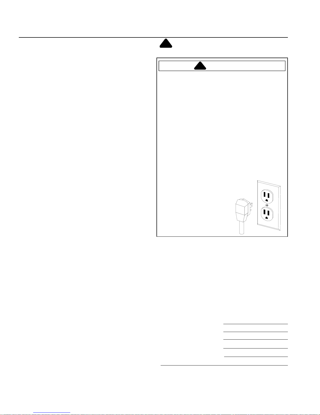
Electrical Grounding Instructions — This refrigerator is
equipped with a three-prong (grounding) plug for
protection against possible shock hazards. If you
encounter a two–prong receptacle, contact a qualified
electrician and have the two-prong wall receptacle
replaced with a properly grounded three-prong wall
receptacle in accordance with the National Electrical
Code.
Refrigerator is designed to operate on a separate 103 to
126 volt, 15 amp., 60 cycle line.
Model Identification
Thank you for purchasing this Imperial® refrigerator.
Please read this Owner's Manual thoroughly . This manual
provides proper maintenance information.
When contacting Broich Enterprises, Inc., provide product
information. Product information is on the serial plate,
located on (upper left corner, ceiling) of Fresh Food
section. Record the following information:
Model Number:
Manufacturing Number:
S/N or Serial Number:
Date of purchase:
Dealer’s name and address:
2
Service
!
!
!
Installation Instructions
Keep a copy of sales receipt for future reference or in
case warranty service is required. Any questions or to
locate an authorized servicer, call 612-941-2270 Monday
through Friday , 8:30 AM through 4:30 PM CST . W arranty
service must be performed by an authorized servicer.
Broich Enterprises, Inc., also recommends contacting an
authorized servicer if service is required after warranty
expires.
DANGER
Proper Disposal of Your
Refrigerator
IMPORTANT: Child entrapment and suffocation
are not problems of the past. Junked or abandoned
refrigerators are still dangerous-even if they will sit for "just a few days." If you
discard an old refrigerator, please follow the
instructions below to help prevent accidents.
BEFORE YOU THROW A W AY YOUR OLD
REFRIGERATOR OR FREEZER:
Proper installation will ensure this refrigerator operates
most efficiently . Broich Enterprises, Inc. cannot be
responsible for improper installation.
1. Remove doors if necessary.
WARNING
T o avoid electrical shock which can cause severe
personal injury or death, disconnect power to
refrigerator before removing doors. After replacing
doors, connect power.
a. Remove toe grille.
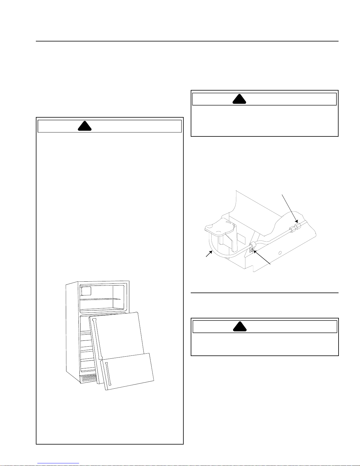
b. Dispenser Models
Loosen water tube clamp screw. Loosen plastic
water tube union nut. Pull water tube away from
union nut and through tube clamp.
A
• T ake off the doors.
• Leave the shelves in place so that children may
not easily climb inside.
C
B
A. Plastic water tube union nut
B. Water tube clamp screw
C. Water tube
Front water line disconnect
c. Remove top hinge covers. (A below)
WARNING
T o avoid electrical shock which can cause severe
personal injury or death, green ground wire must
remain attached to hinge.
3
d. Dispenser Models
!
!
!
g
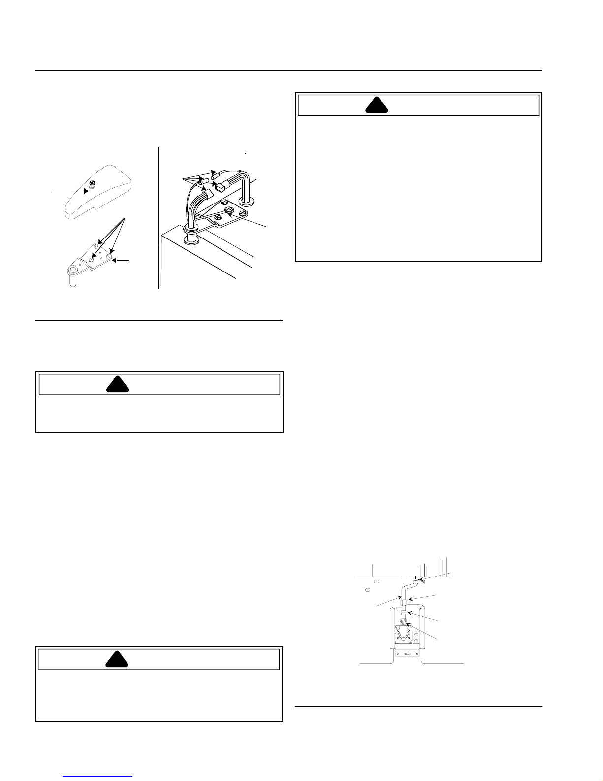
Unplug top hinge wire connectors. Do not remove
green ground wire from hinge. Carefully lift and remove
top hinges. Do not disturb position of hinge shims. (B)
A
C
D
E
C. Hinge cover F. Wire connectors
D. Door hinge screws G. Green ground wire
E. Top hinge
Top hinge removal
e. Remove doors.
B
F
CAUTION
T o avoid property damage, protect soft vinyl or other
flooring with cardboard, rugs, or other protective
material when moving refrigerator.
f. Slide appliance cart under side of refrigerator. W rap
refrigerator with blanket or pad. Thread cart strap
around refrigerator and tighten. Do not overtighten
strap. Move refrigerator in front of final location.
g. Rehang doors by reversing steps a–g. Use a dime at
top of doors to space doors 3/4" (18 mm) from cabinet.
2. Install Water Filtration Cartridge
a. Remove bypass cartridge from water filter head in rear
right corner of refrigerator section. Twist cartridge
counterclockwise 1/4 turn and pull down to remove.
Save bypass for use at a later date.
b. See
Water Filtration System Installation and
Operating Instructions
cartridge for filter installation and operation.
provided with water filter
3. Connecting Water Supply
WARNING
T o avoid electrical shock which can cause severe
personal injury or death, disconnect power to
refrigerator before connecting water supply . After
connecting water supply , connect power.
CAUTION
T o avoid property damage, observe the following:
• Confirm water pressure to water valve is between 20
and 100 pounds per square inch.
• If water filter will be installed, water pressure to water
valve must be a minimum of 35 pounds per square
inch.
• Tighten nut by hand to avoid cross threading. Finish
tightening nuts with pliers and wrenches. Do not
overtighten.
G
• Check for water leaks and correct if necessary
before returning refrigerator to normal location and 24
hours after connecting.
Important
• Before connecting water supply, contact a plumber to
connect copper tubing to household plumbing in
compliance with local codes and ordinances.
• A self–piercing or 3/16" (4.8 mm) saddle valve is not
recommended. Both reduce water flow, become
clogged with time and may cause leaks if repair is
attempted. The correct type of shut off valve requires
a 1/4" (6 mm) hole to be drilled in water supply pipe
prior to valve attachment. The manufacturer is not
responsible for property damage caused by improper
water connection.
Materials Required
1
/4" (6 mm) flexible copper tubing. Length of copper tubing
must reach from water supply connection plus an
additional 8' (2 m) for service loop behind refrigerator.
Procedure
1. Remove plastic cap from water valve inlet port. Place
brass nut and brass sleeve on copper tubing. Insert
copper tubing into water valve inlet port. Connect
brass nut on copper tubing to water valve inlet port.
Confirm copper tubing is secure by pulling on copper
tubing.
"P" clamp
Brass nut
Copper
tubin
A. “P” clamp B. Copper tubing
C. Brass nut D. Brass sleeve
E. Water valve inlet connection
Water supply line connection
Brass sleeve
Water valve
inlet connection
4
2. Turn on water supply to refrigerator and check for
leaks. Correct any leaks.
3. Create service loop using extreme care to avoid
kinks. Secure copper tubing to refrigerator
cabinet with a “P” clamp.
4. Plug in power cord.
5. Move refrigerator into final location.
6. Stabilize refrigerator and align doors.
If refrigerator rocks or is not stable on floor perform
the following:
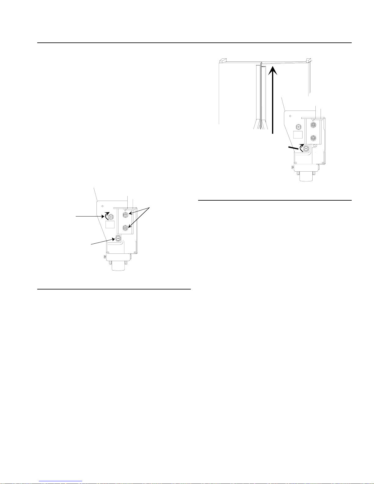
• Determine which rear corner is rocking.
• Remove toe grille to gain access to roller
adjustment screws.
• Turn rear roller adjustment screw clockwise to raise
corner that is rocking.
B
A
B
A
A. Turn roller adjustment screw clockwise to raise door.
B. Continue to turn screw clockwise until doors are level.
Leveling doors
7. Review “Installation Checklist” at back
of manual.
C
A. Rear roller adjustment screw
B. Door hinge screws
C. Front roller adjustment screw
Stabilizing refrigerator
• Check alignment of top of doors. If doors are level
replace toe grille.
If tops of doors are not level perform the following
steps:
• Determine which door must be raised (if toe grille
has not been removed, remove at this time).
• Turn front roller adjustment screw clockwise to
raise front corner of door that needs to be raised.
Roller adjustment screw should be turned until
doors are level.
• Replace toe grille.
5

Controls
!
!
This refrigerator is designed to operate at normal
household temperatures of 55° to 1 10°F (13° to 43°C).
Refrigerator and Freezer Controls
Refrigerator and freezer controls are located on upper rear
wall of refrigerator section.
A
B
A. Freezer control
B. Refrigerator control
Controls
Refrigerator Features
CAUTION
T o avoid property damage, confirm shelf is secure
before placing items on shelf.
Refrigerator Shelves
Model features glass shelves. Shelves adjust up or down
to meet individual storage needs. Shelves hold simple
spills for easier cleaning.
CAUTION
T o avoid personal injury or property damage, handle
tempered glass shelves carefully . Shelves may break
suddenly if nicked, scratched, or exposed to sudden
temperature change.
• Remove shelves by lifting front, releasing hooks
from metal track then pulling out.
• Replace shelves by inserting hooks into metal track
and lowering front.
When freezer control is set to
freezer sections will cool. Initially , set both controls to 4.
Wait 24 hours for refrigerator and freezer sections to
reach desired temperatures. 1 is warmest setting and 7 is
coldest.
off
, neither refrigerator nor
Setting Controls
Set controls with a household thermometer that includes
temperatures between -5°– 50°F (-21°–10°C).
Put thermometer snugly between frozen packages in
freezer section. Wait 5–8 hours. If freezer temperature is
not 0°–2°F (-17°– -16°C), adjust control, 1 number at a
time. Check again after 5–8 hours.
Put thermometer in a glass of water in middle of
refrigerator section. Wait 5–8 hours. If refrigerator
temperature is not 38°–40°F (3°–4°C), adjust control, 1
number at a time. Check again after 5–8 hours.
Shelves
6
 Loading...