

Impediment RS-0800-LVD User Manual

RS-0800-LVD Installation
and User Guide
Part No. 34981-02A
Issue 2.0
January 15, 2004

Notices
The information in this document is subject to change without notice.
While every effort has been made to ensure that all information in this document is accurate, the Authors
accept no liability for any errors that may arise.
No part of this document may be transmitted or copied in any form, or by any means, for any purpose,
without the written permission of the Authors.
Issue 2.0 January 15, 2004 Part No. 34981-02A
ii
RS--0800-LVD User Guide

Contents
iii
Contents
Preface ................................................................................................................................................. vii
International Standards ......................................................................................................................... vii
Potential for Radio Frequency Interference .......................................................................................... vii
European Regulations ............................................. .................................... ... ...................................... viii
Safety .................................................................................................................................................... viii
Rack System Precautions ....................................................................................................................... x
ESD Precautions .................................................................................................................................... x
Data Security ......................................................................................................................................... xi
Special Tools and Equipment ................................................................................................................ xi
Related Documentation ......................................................................................................................... xi
Revision History .................................................................................................................................... xii
1 Introduction ..................................................................................................................................... 1
1.1 RS-0800-LVD Storage System ..................................................................................................1
1.2 The Enclosure Core Product ....................................................................................................... 2
1.2.1 Enclosure Chassis .............................................................................................................. 2
1.2.2 Status Indicator LEDs ......................................................................................................... 3
1.3 The Plug-in Modules ............................................... ... .. ..................................... ... ... .................... 4
1.3.1 Power Supply Module ........................................................................................................4
1.3.2 Cooling Modules ................................................................................................................. 5
1.3.3 Input/Output Module ........................................................................................................... 6
1.3.4 Drive Carrier Modules ........................................................................................................ 9
1.3.5 Dummy Carrier Modules .................................................................................................. 10
1.3.6 Blank Modules .................................................................................................................. 10
1.4 Visible Alarms .............................. ... ...................................................................... ..................... 10
1.5 Technical Specification .............................................................................................................. 11
1.5.1 Dimensions ....................................................................................................................... 11
1.5.2 Weight .............................................................................................................................. 11
1.5.3 Power ............................................................................................................................... 11
1.5.4 Power Cords ..................................................................................................................... 11
1.5.5 Environment ..................................................................................................................... 12
1.5.6 Interfaces .......................................................................................................................... 12
1.5.7 Ultra-320 SCSI I/O Module Specification ......................................................................... 13
1.5.8 Drive Carrier Module Specification ................................................................................... 13
2 Getting Started .............................................................................................................................. 15
2.1 Introduction ................................................................................................................................ 15

iv
RS--0800-LVD User Guide
2.2 Planning Your Installation ......................................................................................................... 15
2.2.1 Enclosure Bay Numbering Convention ............................................................................ 16
2.3 Enclosure Installation Procedures ............................................................................................. 17
2.3.1 Pre-Requisites ................................................................................................................. 17
2.3.2 Rack Mounting Rail Kit .....................................................................................................17
2.3.3 Chassis Installation .......................................................................................................... 18
2.4 Power Supply Module Installation .............................................................................................19
2.4.1 Parts Check List ............................................................................................................... 19
2.4.2 Procedure ........................................................................................................................ 19
2.5 Cooling Module Installation ....................................................................................................... 20
2.5.1 Parts Check List ............................................................................................................... 20
2.5.2 Procedure ........................................................................................................................ 20
2.6 I/O Module Configuration .......................................................................................................... 21
2.6.1 Ultra-320 SCSI Internal Channel Configurations ............................................................. 21
2.6.2 Device SCSI ID Ranges ................................................................................................... 22
2.7 I/O Module Installation .............................................................................................................. 23
2.7.1 Parts Check List ............................................................................................................... 23
2.7.2 Drive Address Ranges ..................................................................................................... 23
2.7.3 Installation Procedure ...................................................................................................... 24
2.7.4 Interface Cable Attachment ............................................................................................. 24
2.8 Drive Carrier Configuration ................................ .. ... .................................................................. 25
2.8.1 Planning and Configuring Your Installation ...................................................................... 25
2.9 Drive Carrier Installation ........................................................... ... .............................................. 25
2.9.1 Parts Check List ............................................................................................................... 25
2.9.2 Procedure ........................................................................................................................ 26
2.9.3 Dummy Carrier Modules .................................................................................................. 28
2.9.4 Engaging the Anti-tamper Locks ...................................................................................... 28
2.10 Power Cord Connection ............................................................................................................ 28
2.10.1 Parts Check List ............................................................................................................... 28
2.10.2 Procedure ........................................................................................................................ 28
2.11 Grounding Checks .......................................... ... .................................... ... .......................
......... 29
3 Operation ....................................................................................................................................... 31
3.1 Before You Begin ................................................. ..................................... ................................ 31
3.2 Power On .......................................................................................................... ........................ 31
3.3 Operator Panel LEDs ................................................................................................................ 31
3.4 Starting the Drives ..................................................................................................................... 32
3.4.1 Disk Drives LEDs ............................................................................................................. 32
3.5 Power Down ................................................................................ .............................................. 32
4 Troubleshooting and Problem Solving ................................................................................ ....... 33
4.1 Overview ................................................................................................................................... 33
4.1.1 Initial Start-up Problems . .................................................................................................. 33
4.2 LEDs ......................................................................................................................................... 34
4.2.1 Power Supply and Cooling Module LEDs ........................................................................ 34
4.2.2 ESI/Ops Pane LEDs ........................................................................................................ 34
4.2.3 Disk Drives LEDs ............................................................................................................. 35
4.3 Troubleshooting ........................................................................................................................ 35
4.3.1 System Faults ........................................ ... ....................................................................... 35
4.3.2 Power Supply Faults ............................................................. .................................... ... ....35
4.3.3 Cooling Module Faults ..................................................................................................... 36

Contents
v
4.4 Drive Carrier Module Faults ...................................................................................................... 36
4.5 Dealing with Hardware Faults ................................................................................................... 36
4.6 Continuous Operation During Replacement .............................................................................. 37
4.7 Replacing a Module ...................................... .. ..................................... ... ................................... 37
4.7.1 Power Supply Module ...................................................................................................... 37
4.7.2 Cooling Module ................................................................................................................ 39
4.7.3 I/O Modules ...................................................................................................................... 40
4.7.4 Drive Carrier Module ........................................................................................................ 42
4.8 Spare Parts and Ancillary Items ................................................................................................ 42
Glossary ................................................................................................................................................ 43
Index ..................................................................................................................................................... 45

vi
RS--0800-LVD User Guide

Preface
vii
Preface
What is in this guide
This user guide gives you step-by-step instructions on how to install, configure and connect the RS-0800LVD storage subsystem to your host computer system, and how to use and maintain the system.
Who should use this guide
This user guide assumes that you have a working knowledge of the Ultra-320 Small Computer Systems
Interface (Ultra-320 SCSI) environment into which you are installing the RS-0800-LVD system. If you do
not have these skills, or are not confident with the instructions in this guide, do not proceed with the
installation.
International St andards
The RS-0800-LVD storage system complies with the requirements of the following agencies and
standards:
• CE to IEC 950/EN60951
• UL 60950
•cUL
Potential for Radio Frequency
Interference
USA Federal Communications Commission (FCC)
Note This equipment has been tested and found to comply with the limits for a class B digital device, pursuant
to Part 15 of the FCC rules. These limits are designed to provide reasonable protection against harmful
interference when the equipment is operated in a commercial environment. This equipment generates,
uses and can radiate radio frequency energy and, if not installed and used in accordance with the
instruction manual, may cause harmful interference to radio communications. Operation of this
equipment in a residential area is likely to cause harmful interference in which case the user will be
required to correct the interference at his own expense.
Properly shielded and grounded cables and connectors must be used in order to meet FCC emission
limits. The supplier is not responsible for any radio or television interference caused by using other than
recommended cables and connectors or by unauthorized changes or modifications to this equipment.
Unauthorized changes or modifications could void the user’s authority to ope rate the equipment.
This device complies with Part 15 of the FCC Rules. Operation is subject to the following two conditions:
(1) this device may not cause harmful interference, and (2) this device must accept any interference
received, including interference that may cause undesired operation.
RS--0800-LVD User Guide
viii
European Regulations
This equipment complies with European Regulations EN 55022 Class B: Limits and Methods of
Measurement of Radio Disturbance Characteristics of Information Technology Equipments and EN
50082-1: Generic Immunity.
Safety
All plug-in modules are part of the fire enclosure and must only be removed when a replacement can be
immediately added. The system must not be run without all units in place.
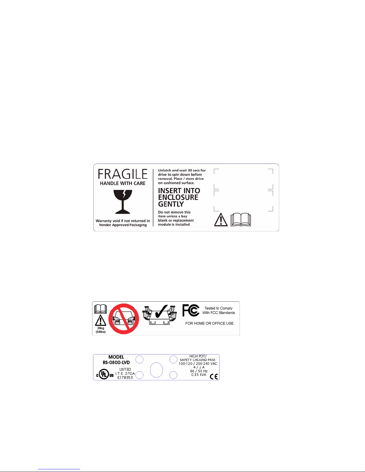
Permanently unplug the unit if you think that it has become damaged in any way and before you move it.
Drive Carrier Module Caution Label: Do not operate with modules missing; spin down time 30
seconds
• An RS-0800-LVD enclosure can weigh up to 24kg (53lb ). Do not try to lift it by your self.
• Do not lift the RS-0800-LVD by the handles on the PSU module, they are not designed to support
the weight of the populated enclosure.
Chassis Labels
• In order to comply with applicable safety, emission and thermal requirements no covers should be
removed and all bays must be fitted with plug-in modules.

Preface
ix
Plug-in Module Caution Label: Do not operate with modules missing
• The RS-0800-LVD unit must only be operated from a power supply input voltage range of 100 -120
VAC or 200- 240 VAC.
• The plug on the power supply cord is used as the main disconnect device. Ensure that the socket
outlets are located near the equipment and are easily accessible.
• If powered by multiple AC sources, disconnect all supply power for complete isolation
PSU Warning Label: Power Hazards
• The power connection must always be disconnected prior to removal of the Power Supply module
from the enclosure.
• A safe electrical earth connection must be provided to the power cord. Check the grounding of the
enclosure before applying power.
• Provide a suitable power source with electrical overload protection to meet the requirements laid
down in the technical specification.
Caution Caution: If this equipment is used in a manner not specified by the manufacturer, the protection provided
by the equipment may be impaired.
Warning The rear modules are retained by 2 off brackets (+ 4 fixing screws) and are not operator
removable. these modules must only be removed by trained maintenance technicians who are
aware of the hazards associated with the PSUs.
Power must not be applied to the PSU when it is out of the RS-0800-LVD enclosure.The PSU does
not have complete safety covers.
Do not remove covers from the PSU. Danger of electric shock inside. Return the PSU to your
supplier for repair.

RS--0800-LVD User Guide
x
Rack System Precautions
The following safety requirements must be considered when the unit is mounted in a rack.
• The rack design should incorporate stabilizing features suitable to prevent the rack from tipping or
being pushed over during installation or in normal use.
• When loading a rack with the units, fill the rack from the bottom up and empty from the top down.
• The rack should comply with the airflow requirements detailed in the user guide.
• The system must be operated with low pressure rear exhaust installation (back pressure) created
by rack doors and obstacles not to exceed 5 pascals (0.5mm water gauge).
• The rack design should take into consideration the maximum operating ambient temperature for the
unit, which is 35°C with a single cooling module fitted and 40°C when dual cooling modules are
fitted.
• The rack should have a safe electrical distribution system. it must provide overcurrent protection for
the unit and must not be overloaded by the total number of units installed in the rack. Consideration
of the units nameplate rating should be used when addressing these concerns.
• The electrical distribution system must provide a reliable earth for each unit and the rack.
• Each power supply in each unit has an earth leakage current of 0.8mA. The design of the electrical
distribution system must take into consideration the total earth leakage current from all the power
supplies in all the units. The rack will require labelling with "HIGH LEAKAGE CURRENT. Earth
connection essential before connecting supply".
• The rack when configured with the units must meet the safety requirements of UL60950 and IEC
60950.
• Each power supply in each unit has an earth leakage current of 0.8mA. The design of the electrical
distribution system must take into consideration the total earth leakage current from all the power
supplies in all the units. The rack will require labelling with "HIGH LEAKAGE CURRENT. Earth
connection essential before connecting supply".
• The rack when configured with the units must meet the safety requirements of UL1950 and IEC
60950.
ESD Precautions
Caution It is recommended that you fit and check a suitable anti-static wrist or ankle strap and observe all
conventional ESD precautions when handling RS-0800-LVD plug-in modules and components. Avoid
contact with backplane components and module connectors, etc.

Preface
xi
Data Security
• Power down your host computer and all attached peripheral devices before beginning installation.
• Each enclosure contains up to 8 removable disk drive modules. Disk units are fragile. Handle them
with care, and keep them away from strong magnetic fields.
• All the supplied plug-in modules and blanking plates must be in place for the air to flow correctly
around the enclosure and also to complete the internal circuitry.
• If the subsystem is used with modules or blanking plates missing for more than a few minutes, the
enclosure can overheat, causing power failure and data loss. Such use may also invalidate the
warranty.
• If you remove any drive module, you may lose data.
– If you remove a drive module, replace it immediately. If it is faulty, replace it with a drive module
of the same type and capacity
• Ensure that all disk drives are removed from the enclosure before attempting to manhandle or move
the rack installation.
• Do not abandon your backup routines. No system is completely foolproof.
Special Tools and Equipment
There are no special tools required but in order to complete the assembly of some configurations you may
need the following (not supplied):
• Cross head and slotted screwdrivers.
• Security keys (one of these should be included with your RS-0800-LVD enclosure for use with the
drive locks).
Related Documentation
• RS-0800-LVD Quick Installation Guide (P/N 34943-03)
• RS-Salient Series Rack Installation Guide (P/N 43638-02)

RS--0800-LVD User Guide
xii
Revision History
Version Date Description of Change
1.0 January, 2002 Initial Release
2.0 January, 2004 Revised throughout to include additional safety and insta llation
information and editorial enhancements.
Preface
• Safety information revised and illustrations of various safety labels
included.:
Chapter 1
• New illustrations of PSU, Cooling and I/O modules inserted.
Chapter 2
• New illustrations of.rack mounting kit and retaining brackets
inserted.
Chapter 4
• New illustrations showing removal of PSU, Cooling and I/O modules
inserted.
Introduction
1
Chapter 1
Introduction
1.1 RS-0800-LVD Storage System
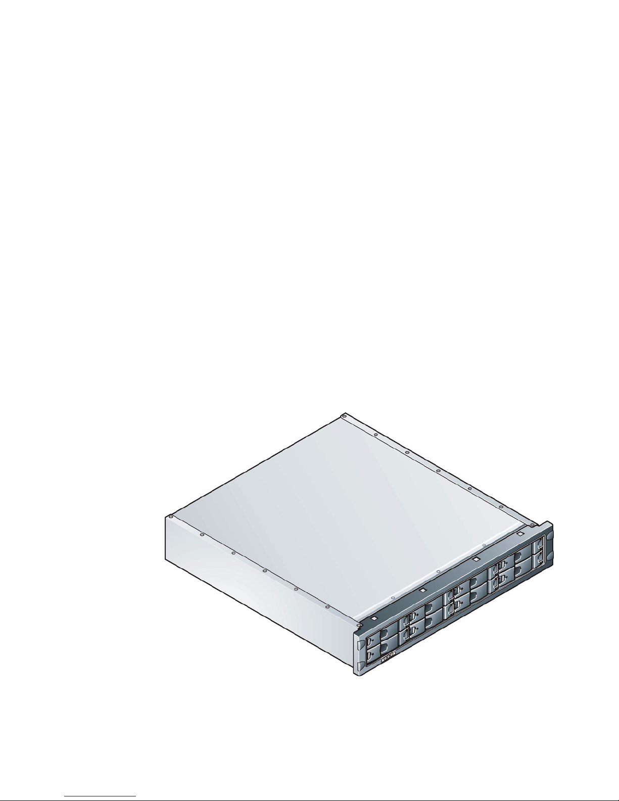
This manual provides information to assist in the installation and maintenance of an RS-0800-LVD Two
Channel enclosure subsystem.
Figure 1–1 The RS-0800-LVD System
RS--0800-LVD User Guide
2
1.2 The Enclosure Core Product
The RS-0800-LVD enclosure design concept is based on a subsystem together with a set of plug-in
modules.
The RS-0800-LVD subsystem as supplied comprises:
• Chassis and Backplane with integral status indicator LEDs.
• Power Supply plug-in modules, in accordance with your required configuration (see Figure 1–7).
• Cooling plug-in module (see Figure 1–9
• Ultra-320 SCSI Input/Output module. (See Figure 1–10).
• optional Loopback module
• Ultra-320 SCSI Drive Carrier modules and associated dummy carrier modules (see Figure 1–15).
• Blank modules, as required to complete your planned configuration and installation.
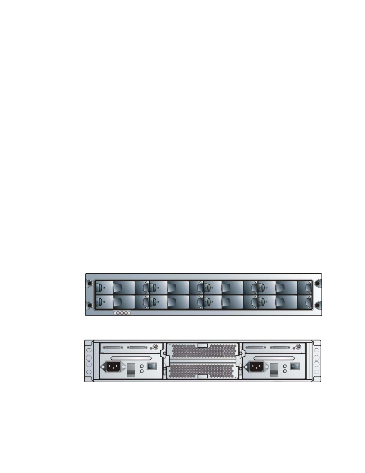
1.2.1 Enclosure Chassis
The chassis consists of a sheet metal enclosure assembly containing a Backplane PCB and module
runner system.
The chassis assembly contains 8 drive bays at the front, each of which accommodates a plug-in drive
carrier module. The 8 drive bays are arranged in 2 rows of 4 drives. At the rear, the chassis assembly
contains 6 module bays to house Power Supply modules, Cooling modules and SCSI I/O modules.
The Backplane PCB provides logic level signal and low voltage power distribution paths. Figure 1–2 and
Figure 1–3 show front and rear views of an RS-0800 chassis respectively.
• The chassis is fitted with 19 inch Rack mounting features which enables it to be fitted to standard 19
inch racks and uses 2EIA units of rack space.
Figure 1–2 Enclosure Chassis (Front)
Figure 1–3 Enclosure Chassis (Rear, 2 x 4 I/O Modules fitted)
Introduction
3
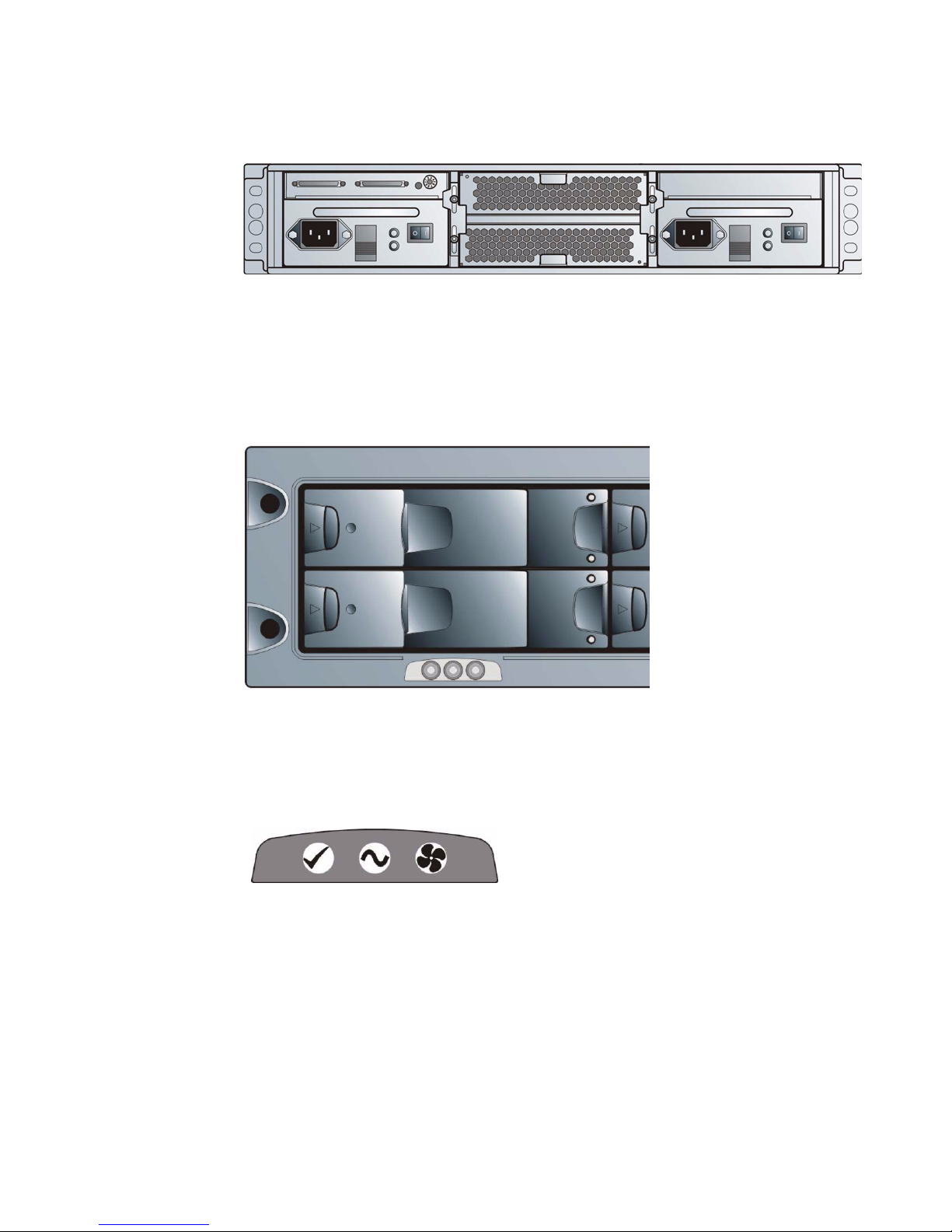
1.2.2 Status Indicator LEDs
Supplied as part of the Enclosure core product, the Enclosure System Interface/Operators (ESI/Ops)
panel is shown in Figure 1–5
‘
The ESI/Ops Panel provides the enclosure with a micro controller which is used to monitor and control
all elements of the Enclosure. Each element (Power, Cooling, Device status) is interfaced to the
processor.
1.2.2.1 Ops Panel Indicators
The Operator Panel includes Light Emitting Diode (LED) indicators which show the status for all modules.
The indicators listed in the following table are located from left to right on the panel, as shown in Figure
1–6.
Figure 1–4 Enclosure Chassis (Rear, 2 x 4 I/O and 1 x 8 Loopback Modules fitted)
Figure 1–5 ESI/Ops Panel
Figure 1–6 Ops Panel Indicators
RS--0800-LVD User Guide
4
1.3 The Plug-in Modules
An RS-0800-LVD Enclosure requires one or more of the following modules for normal operation:
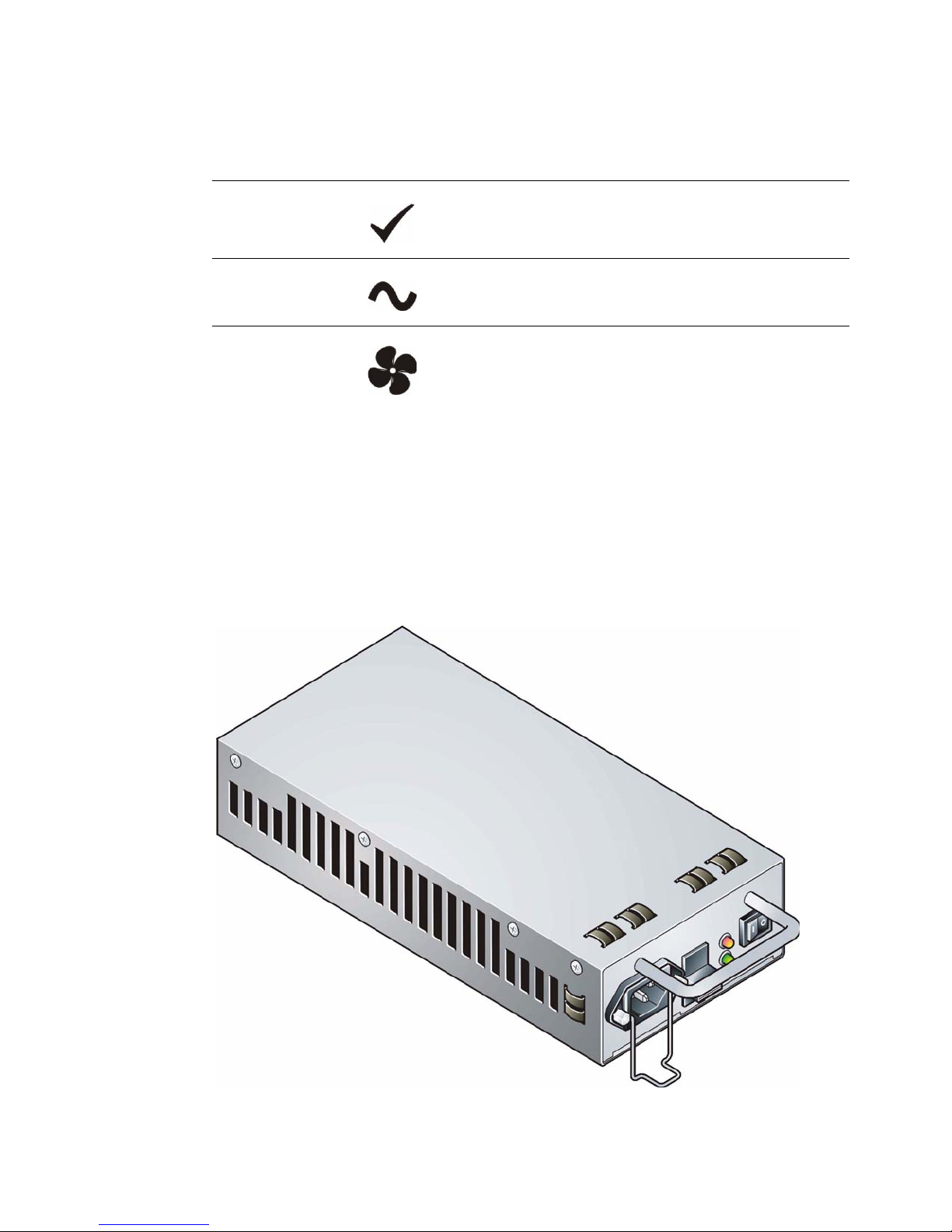
1.3.1 Power Supply Module
One Power Supply module is supplied mounted in the rear of the enclosure as part of the subsystem core
product. (Figure 1–7)
LED Indicator Symbol Meaning
System Status Green to signify that there is power applied to the enclosure.
Amber if the ESI processor has failed.
Power Status Green if the power supply/supplies are functioning normally,
Amber if there is a PSU failure in a dual powered en cl o s ure.
Cooling Status Green if all fans are functioning correctly.
Amber if there is a fan failure in any module.
Figure 1–7 Power Supply Module
Introduction
5
Optionally, a second Power Supply plug-in module can be fitted.
PSU voltage operating ranges are nominally 115V or 230V, selected automatically.
Two LEDs are mounted on the front panel of the Power Supply module (see Figure 1–4). To indicate the
status of the PSU.
1.3.1.1 Multiple Power Supply Modules
If you have two Power Supply modules fitted, they operate together. If one fails the other maintains the
power supply while you replace the faulty unit.
Important Module replacement should only take a few minutes to perform but must be completed within 10
minutes from removal of the failed module. Alternatively, if there is no replacement module
available, a Power Supply blanking module could be fitted after removing the faulty module.
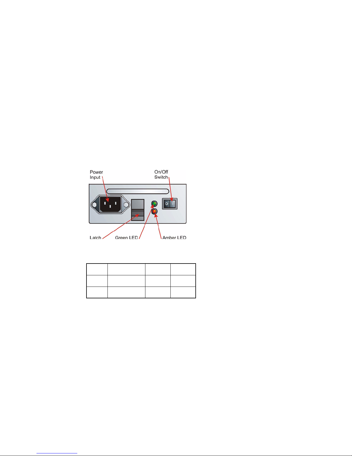
1.3.1.2 Power Supply Indicators
PSU Panel
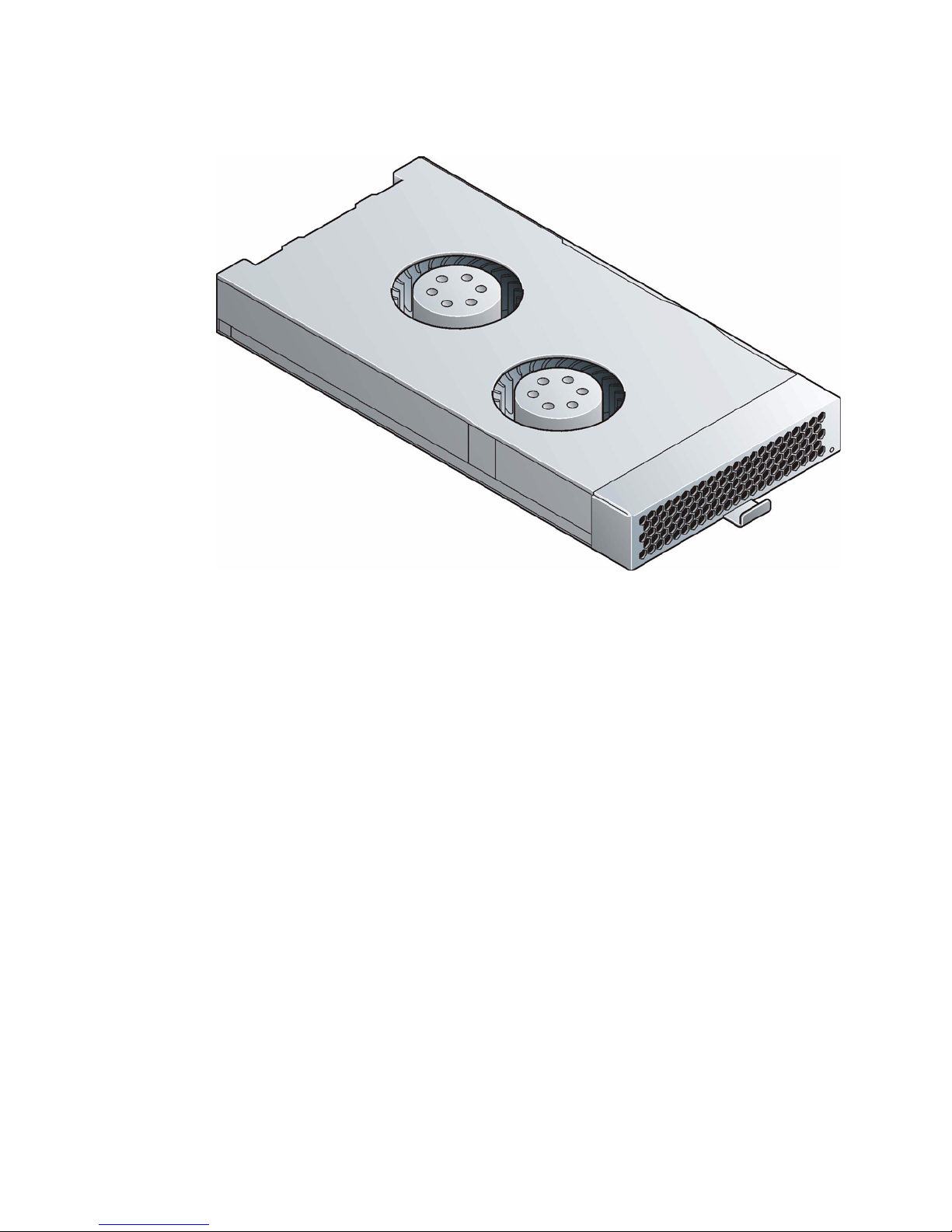
1.3.2 Cooling Modules
One Cooling module is supplied mounted in the rear of the enclosure as part of the subsystem core
product (Figure 1–9).
Figure 1–8 PSU LEDs
Table 1–1PSU LEDs
LED Definition Normal Fault
Green Power Output ON OFF
Amber PSU/Fault OFF ON
RS--0800-LVD User Guide
6
A status indicator LED is mounted on the front panel of the Cooling module.
Optionally, a second Cooling module can be fitted.
1.3.3 Input/Output Module
The Input/Output (I/O) modules have been designed for integration into an RS-0800-LVD enclosure,
utilizing Ultra-320 SCSI interfacing with the host computer system.
Three versions of I/O module are available:
• 2 x 4 I/O module (Figure 1–10) incorporates 2 VHDCI connectors for main I/O purposes and switch
to set the SCSI-ID range. Two of these modules will be required for the 2 x 4 configuration and one
will be used in the 1 x 8 configuration.
• 1 x 8 Ultra-320 SCSI Loopback module (Figure 1–11) with no external connectors. This will be used
in conjunction with a 2 x 4 I/O module to create a 1 x 8 bus structure. This module has no switches
fitted.
• 1 x 8 Ultra-160 SCSI Loopback module (Figure 1–12) with no external connectors. This will be used
in conjunction with a 2 x 4 I/O module to create a 1 x 8 bus structure. This module has no switches
fitted.
The 2 Channel Ultra-320 SCSI I/O modules are housed in the top right and left hand rear bays. If a
loopback module is used it must only be fitted in the right hand bay, as viewed from the rear.
Important Two modules are always required.
Figure 1–9 Cooling Module
 Loading...