

Page 1

Owner's Manual
Split Type Wall-mounted Air Conditioner
Model:
Thank you for choosing our product.
For proper operation, please read and keep this manual carefully.
If you have lost the Owner’s Manual, please contact the local agent or
visit www.impecca.com for an electronic version.
ISMO-1821
v
. 1.1
Page 2
In line with the company
’s policy of continual product improvement, the aesthetic and dimensional
characteristics, technical data and accessories of this appliance may be changed without notice.
CONTENTS
Conformity And Range
The Instructions Before Use
Name of Parts
Technical Data
GENERAL
INFORMATION
Outdoor Unit Working Temperature Range
Electrical Connections
Installing The Outdoor Unit
Bleeding
Maintenance
Installation Dimension Diagram
INSTALLER
Check After Installation
GENERAL INFORMATION
1
2
3
4
4
5
8
6
7
7
8
The products in this manual may be different with the rea one, according to different models, l
some models have displayer and some models without displayer, the position and shape of
the displayer please refer to the real one.
This appliance is not intended for use by persons (including children) with reduced physical,
sensory or mental capabilities, or lack of experience and knowledge, unless they have been
given supervision or instruction concerning use of the appliance by a person responsible for
their safety.
Children should be supervised to ensure that they do not play with the appliance.
This marking indicates that this product should not be disposed with other
household wastes throughout the EU. To prevent possible harm to the
environment or human health from uncontrolled waste disposal, recycle
it responsibly to promote the sustainable reuse of material resources. To
return your used device, please use the return and collection systems or
contact the retailer where the product was purchased. They can take this
product for environmental safe recycling.
Page 3
Explanation of Symbols
Indicates a hazardous situation that, if not avoided, will result in death
or serious injury.
Indicates a hazardous situation that, if not avoided, could result in death
or serious injury.
Indicates a hazardous situation that, if not avoided, may result in minor
or moderate injury.
Indicates important but not hazard-related information, used to indicate
risk of property damage.
Indicates a hazard that would be assigned a signal word
WARNING or CAUTION.
CONFORMITY AND RANGE
Please read this owner's manual carefully before operating the unit and keep it carefully for consultation.
Instructions for installation and use of this product are provided by the manufacturer.
Only use the air conditioner as instructed in this booklet. These instructions are not intended to
cover every possible condition and situation. As with any electrical household appliance, common sense
and caution are therefore always recommended for installation, operation and maintenance.
GENERAL INFORMATION
1
Page 4
THE INSTRUCTIONS BEFORE USE GENERAL INFORMATION
WARNING
When having a burning smell or
★ ★
smoke,please turn off the power
supply and contact with the service center.
If the abnormity still exists,the unit
may be damaged,and may cause
electric shock or fire.
Power must adopts the special
★
circuit to prevent fire.
Otherwise, it can cause electric
shock or fire.
★ ★
Otherwise,the accumulated dusts
may cause overheating or fire.
The power supply must adopt the
special circuit that with air switch
protection and assure it has enough capacity.The unit will be turned
on or off according to your requirement automatically,please do not
turn on or turn off the unit frequently,otherwise disadvantage effect
may be caused to the unit.
Disconnect the power supply if
long putting the air conditioner
out of use.
Never cut off or damage power
★
cables and control wires. If the
power cable and signal control
wire were damaged, change
them by professional.
Never damage the electric wire
or use the electric wire which is
not appointed.
Otherwise,it will cause overheating
or fire.
When cleaning,it is necessary
★ ★
to stop driving and turn off the
power supply.
Cut off power supply
Otherwise,it may cause electric
shock or damage.
Please note whether the insta-
★ ★
lled stand is firm enough or not.
Rated voltage of this air conditioner 220-240V, 60Hz, The compressor will vibrate sharply if the
voltage is too low, resulting in
damage to refrigerating system.
Electrical component are easy to
damage if the voltage is too high.
Don't step on the top of the
outdoor unit or place something
on it.
Don't attempt to repair the air
★
conditioner by yourself.
The wrong repair will lead to an
electric shock or fire,so you should
contact the service center to repair.
Earthing: The unit must be reli-
★
ably earthed.The earthing cable
shall be connected to the special earthing device in the construction.
If it is damaged, it may lead to the
fall of the unit and cause the injury.
As falling off the outdoor unit can be
dangerous.
2
Page 5
NAME OF PARTS
GENERAL INFORMATION
WARNING
Be sure to cut off the power supply before cleaning the air conditioner; otherwise electric
shock might happen.
Wetting of air conditioner may cause the risk of electric shock. Make sure not to wash
your air conditioner in any case.
Volatile liquids such as thinner or gasoline will cause damage to the appearance of air
conditioner. (Only use soft dry cloth moist cloth clean the air conditioner cabinet).
This product must not be disposed together with the domestic waste.
This product has to be disposed at an authorized place for recycling of electrical and
electronic appliances.
The temperature of refrigerant circuit will be high,please keep the interconnection cable
away from the copper tube.
1
OUTDOOR UNIT
No. Description
1 Air outlet grille
2 Valve
Note: The above figures are only intended to a simple
diagram of the appliance and may not correspond to the
appearance of the units that have been purchased.
2
TECHNICAL DATA GENERAL INFORMATION
MODE
Electrical data
Electricity supply
Fuse or air switch
Minimum power cord section
Size and clearance
L
P
L
P
H
H
ISMO-1821
208/230V,60HZ
20
2.5
890
362
700
mm
mm
mm
mm
2
OUTDOOR UNIT WORKING TEMPERATURE RANGE GENERAL INFORMATION
OutdoorsideDB/WB(c)
Maximum cooling
Maximum heating
48/27/-
3
Page 6
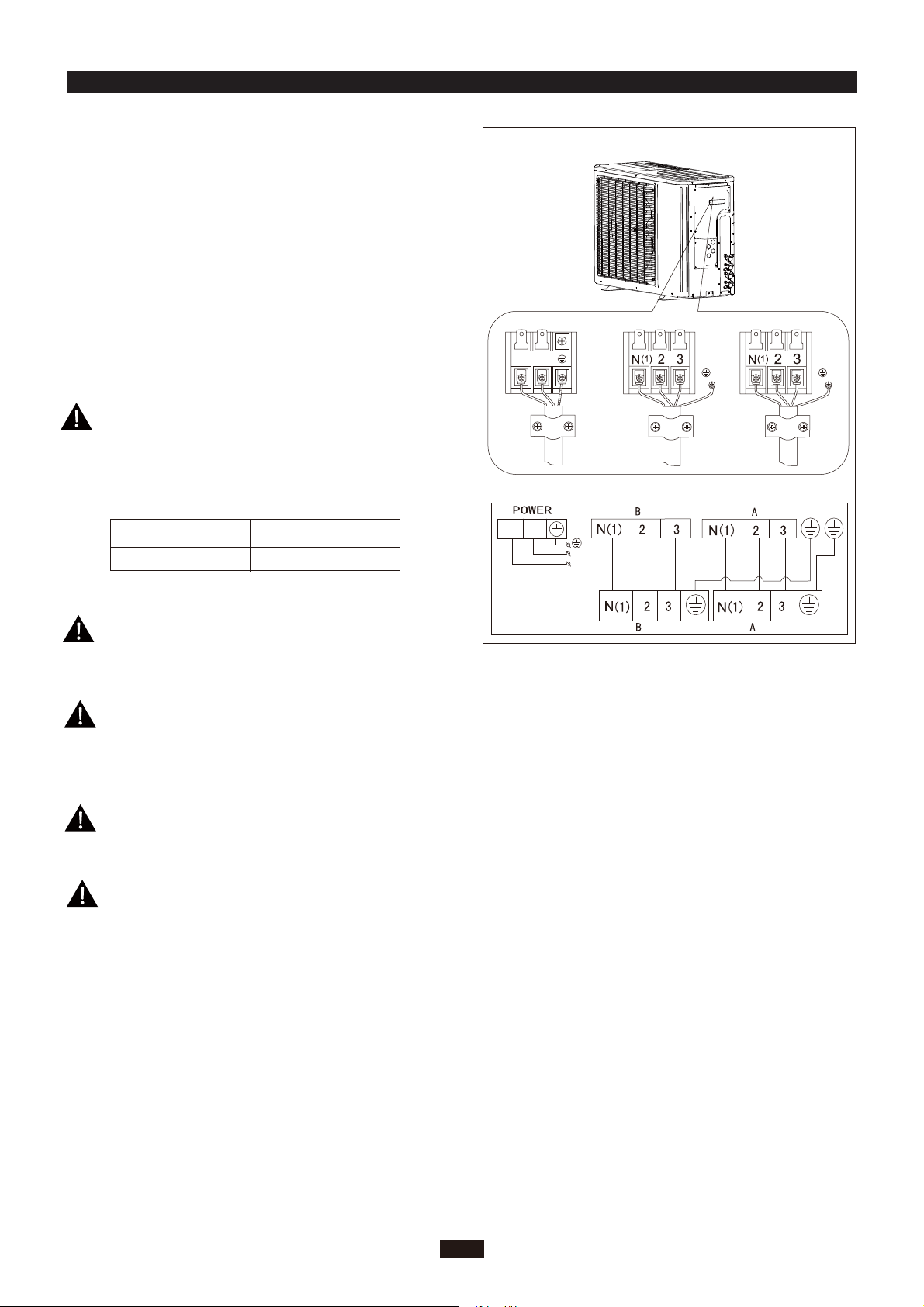
ELECTRICAL CONNECTIONS
1. Remove the handle at the right side plate of the outdoor
unit (one screw).
2. Remove the cable clamp, connect the power connection
cable with the terminal at the row of connection and fix
the connection. The fitting line distributing must be
consistent with the indoor unit. terminal of line bank.
Wiring should meet that of indoor unit.
3. Fix power connection wire by wire clamp.
4. Ensure wire has been fixed well.
To unit A
INSTALLER
To unit B
5. Install the handle.
Including an air switch with suitable capacity,
please note the following table. Air switch
should be included magnet buckle and heating
buckle function, it can protect the circuit-short
and overload. (Caution: please do not use the
fuse only for protect the circuit)
Air switch capacityAir-conditioner
ISMO-1821
25A
An all-pole disconnection switch having a contact
separation of at least 3mm in all pole should be
connected in fixed wiring.
Wrong wire connection may cause malfunction of
some electric components.After fixing cable, ensure
that leads between connection to fixed point have
some space.
L1
L1 L2
L2
Power cord
connecting
cable
L2
L1
connecting
cable
To the power supply
The connection pipes and the connectiong wirings
of the unit A and unit B must be corresponding to
each other respective.
The appliance shall be installed in accordance with
national wiring regulations.
Note: the above figures are only intended to be a simple
diagram of the appliance and may not correspond to the
appearance of the units that have been purchased.
4
Page 7
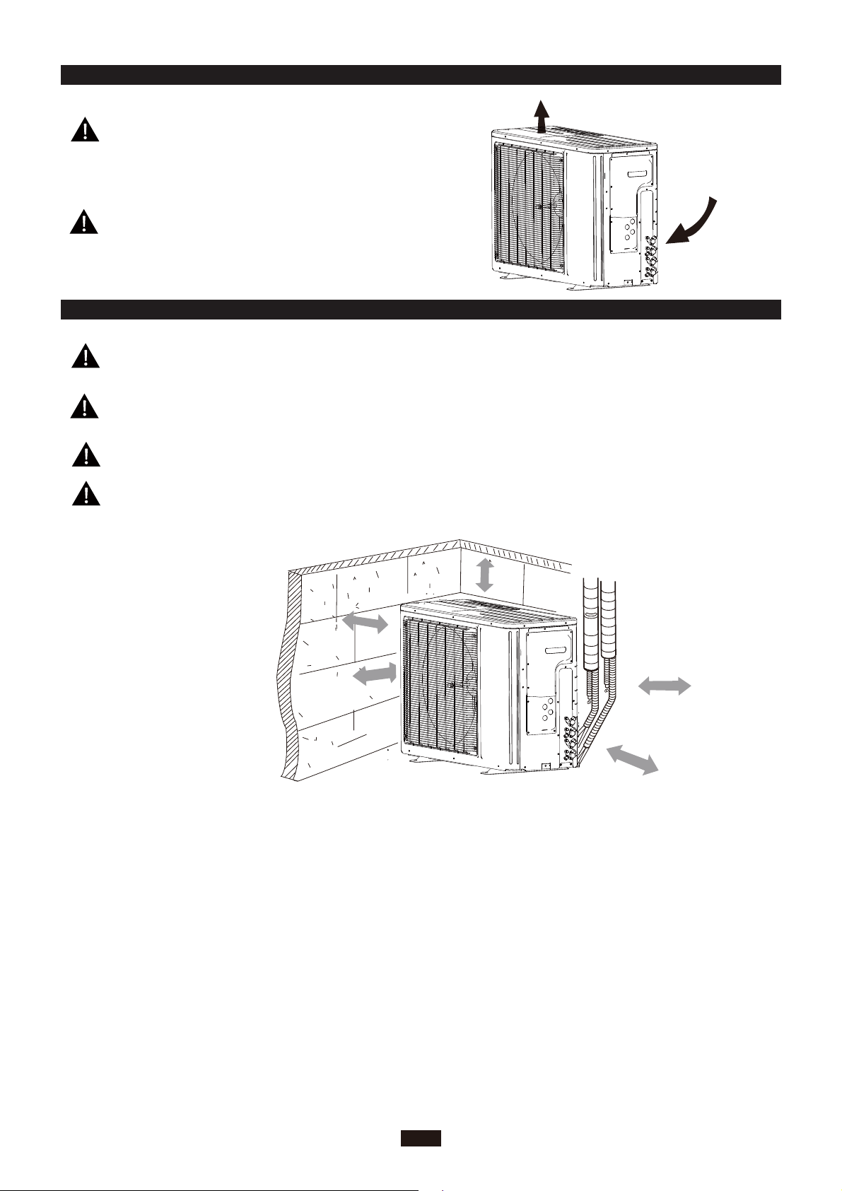
INSTALLING THE OUTDOOR UNIT INSTALLER
Location
Use bolts to secure the unit to a flat, solid floor.
When mounting the unit on a wall or the roof, make
sure the support is firmly secured so that it cannot
move in the event of intense vibrations or a strong
wind.
Do not install the outdoor unit in pits or air vents
●
Installing the pipes
Use suitable connecting pipes and equipment for
the refrigerant R410A.
Model(m) 1821x2
Max. connection pipe length
Max. connection pipe length
(Simple one indoor unit)
The refrigerant pipes must not exceed the maximum
heights 5m(1821K).
Wrap all the refrigerant pipes and joints.
Tighten the connections using two wrenches wor-
king in opposite directions.
Caution: Installation Must be Performed in Accordance
with the NEC/CEC by Authorized Personnel Only.
20
10
Install the drain fitting and the drain hose
(for model with heat pump only)
Condensation is produced and flows from the outdoor unit when the appliance is operating in the
heating mode. In order not to disturb neighbours
and to respect the environment,install a drain fitting
and a drain hose to channel the condensate water.
Install the drain fitting and rubber washer on the
outdoor unit chassis and connect a drain hose to it
as shown in the figure.
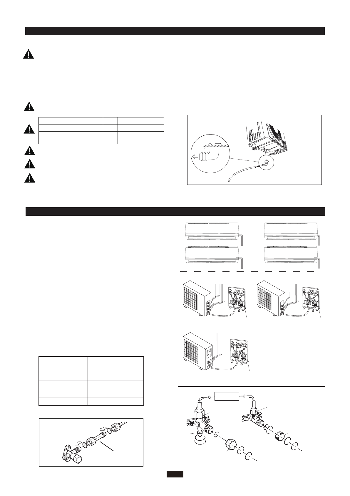
BLEEDING INSTALLER
Humid air left inside the refrigerant circuit can cause compressor malfunction. After having connected the indoor
and outdoor units, bleed the air and humidity from the
refrigerant circuit using a vacuum pump.
(1) Unscrew and remove the caps from the 2-way and 3-
way valves.
(2) Unscrew and remove the cap from the service valve.
(3) Connect the vacuum pump hose to the service valve.
(4) Operate the vacuum pump for 10-15 minutes until an
absolute vacuum of 10 mm Hg has been reached.
(5) With the vacuum pump still in operation, close the
low-pressure knob on the vacuum pump coupling.
Stop the vacuum pump.
(6) Open the 2-way valve by 1/4 turn and then close it
after 10 seconds. Check all the joints for leaks using
liquid soap or an electronic leak device.
(7) Turn the body of the 2-way and 3-way valves. Discon nect the vacuum pump hose.
(8) Replace and tighten all the caps on the valves.
Diameter (mm)
Φ9.52
Φ16
Φ12
Φ19
Twisting moment (N.m)
15-20Φ6
35-40
60-65
45-50
70-75
18K unit need to be installed the indoor unit
18K MODE:
conversion joint
Service
inlet
(2)Turn
(8) Secure
Refrigerant fluid di
3-way valve
Vacuum pump Vacuum pump
Vacuum pump
INDOOR
UNIT
rection of fiow
(7)Turn to open fully
Valve cap
(8) Secure
2-way valve
(6) Open by 1/4 turn
(7)Turn to open fully
(2)Turn
alve cap
V
(2)Turn
(8) Secure
Connect to the
indoor unit
5
Page 8
MAINTENANCE INSTALLER
Use suitable instruments for the refrigerant R410A.
Do not use any other refrigerant than R410A.
●
Do not use mineral oils to clean the unit.
INSTALLATION DIMENSION DIAGRAM INSTALLER
The installation must be done by trained and qualified service personnel with reliability according to this
manual.
Contact service center before installation to avoid the malfunction due to unprofessional installation.
When picking up and moving the units, you must be guidedby trained and qualified person.
Ensure that the recommende dspace is left around the appliance.
50c
Space to the cover
or above
30cm
Space to the cover
or above
200cm
(Air outlet side)
m
or more
30cm
(Air inlet side)
50cm
Space to the wall
or above
or above
6
Page 9
CHECK AFTER INSTALLATION INSTALLER
Check Items
Is the installation reliable?
Has the gas leakage been checked?
Is the thermal insulation of the unit
sufficient?
Is the drainage smooth?
Does the power supply voltage accord
with the rated voltage specified on the
nameplate?
Are the lines and pipelines correctly
installed?
Has the unit been safely grounded?
Problems Owing to Improper Installation
The unit may drop, vibrate or make noises
May cause unsatisfactory cooling (heating)
effect
May cause condensation and water dropping
May cause condensation and water dropping
The unit may bread down or the components
may be burned out
The unit may bread down or the components
may be burned out
Risk of electrical leakage
Are the models of lines in conformity
with requirements?
Are there any obstacles near the air
inlet and outlet of the indoor and outdoor units?
Have the length of refrigerating pipe
and refrigerant charge amount been
recorded?
The unit may bread down or the components
may be burned out
The unit may bread down or the components
may be burned out
It is not easy to decide the charge amount
of refrigerant.
7
Page 10

CUSTOMER S
Before contacting customer support, please see the troubleshooting guide above.
Visit our website to contact us, find answers to Frequently Asked Questions, and for other
resources which may include an updated version of this user's guide.
UPPORT
WWW.IMPECCA.COM
If you wish to contact us by phone, please be sure to have your model number and serial
number ready and call us between 9:00am and 6:00pm ET, at +1 866-954-4440.
Keep tabs on Impecca's newest innovations & enter contests via our social network feeds:
www.facebook.com/Impecca/
www.instagram.com/impecca/
@impeccausa
Page 11

Page 12

© 2016 Impecca, a division of LT Inc., Wilkes Barre, PA.
Page 13

Flex Series R410A GMV Multi VRF
Floor and Ceiling Type
Indoor Unit (For North America)
Owner's Manual
Commercial Air Conditioners
Models:
ISMI-FC18
ISMI-FC24
Thank you for choosing Commercial Air Conditioners, please read this
owner’s manual carefully before operation and retain it for future reference.
v 1.1
Page 14

User Notice
When installing, the entire capacity of the cooperating indoor unit should be not larger than
◆
150% of outdoor unit, otherwise, it will cause the shortage of cooling (heating) capacity.
The power supply of the entire unit must be the power supply of outdoor unit. And disconnect
◆
the main power of outdoor unit before cleaning.
In order to start up the unit successfully, the main power switch should be opened 8 hours
◆
before the operation.
After receiving the turn off signal, every indoor unit will continue to work for 20-70sec to
◆
make good use of the rest cool air or the rest heat air in the heat exchanger, which will prepare for
the next operation. And this is normal.
When the selected operating mode of the indoor unit is conflicted to the operating mode of
◆
the outdoor unit, 5 sec later, the malfunction hint will be shown on the indoor unit or wired controller,
then the indoor unit will stop. At this time, change the operating mode of the indoor unit to the one
that would not conflict with the outdoor operating mode to make the operation normal. The HEAT
mode conflicts with each of the COOL mode, DRY mode and FAN mode, while the COOL mode,
DRY mode and FAN mode are compatible between each other.
The appliance shall not be installed in the laundry. The appliance shall not be used by
◆
children without supervisor.
Power supply fluctuating range (+/-10%, +/-1Hz)
◆
Humidity range: 30%~95%.
◆
Main switch provided by end user: main switch handle should be black or gray, it can be
◆
locked in “OFF” position with padlock.
The main disconnection device should be installed at a height of 0.6~1.7m. Over current
◆
protection is required(UL 1995,CSA C22.2).
The cooling range of the unit is the outdoor ambient temp -5~48℃ DB, the heating range of
◆
the unit (only for the heat pump type unit) is the outdoor ambient temp. -15~27℃ DB.
This appliance is not intended for use by persons (including children) with reduced physical,
◆
sensory or mental capabilities, or lack of experience and knowledge, unless they have been given
supervision or instruction concerning use of the appliance by a person responsible for their safety.
Children should be supervised to ensure that they do not play with the appliance.
This product must not be disposed together with the domestic waste. This product has
to be disposed at an authorized place for recycling of electrical and electronic appliances.
Thank you for selecting Impecca air conditioner. Before use, please read this
manual carefully and keep it properly for furthur reference.
Page 15

Contents
1 Safety Precautions .......................................................................................... 1
2 Installation Precautions and Location Choosing ............................................. 2
2.1 Installation Precautions ......................................................................................... 2
2.2 Location Choosing ................................................................................................ 2
2.3 Imappropriate Location ......................................................................................... 2
3 Installation of Floor and Ceiling Type Indoor Unit ............................................ 3
3.1 Space Dimension for Unit Installation ................................................................... 3
3.2 Important Notice .................................................................................................... 3
3.3 Installation Description .......................................................................................... 3
3.4 Electrical Wiring .................................................................................................... 6
3.5 Drainpipe Installation ............................................................................................ 7
3.6 Install the Connection Pipes ................................................................................. 8
4 Part Names of Floor and Ceiling Type Indoor Unit ........................................ 10
5 Working Temperature Range ......................................................................... 11
6 Maintenance Method ..................................................................................... 12
6.1 Cleaning the Air Filters ........................................................................................ 12
6.2 Cleaning the Unit ................................................................................................ 12
6.3 At the Start of the Season ................................................................................... 12
6.4 During the off Season ......................................................................................... 12
7 Operating Instructions ................................................................................... 13
8 Malfunction Analysis ...................................................................................... 15
8.1 Service Center ..................................................................................................... 15
8.2 After-sales Service ............................................................................................... 16
Page 16

Flex Series for North America
1 Safety Precautions
Please read this manual carefully before using this unit. Operate it correctly according to the
guide in this manual.
Please pay special attention to the indicating meaning of these two marks:
Warning! This mark means that the unit may cause property damage, personal injury or
loss of life if the operation is incorrect.
Caution! This mark means that the unit may cause minor or moderate property damage or
personal injury.
Warning!
The unit should be earthed reliably. Do not connect the earth line to the gas pipe, water pipe,
◆
drainage pipe or other unsafe places in potential.
Air conditioner must use special power supply circuit and switches for creepage protect and
◆
air with enough capacity should be installed in the circuit.
Ensure that the connecting of power cord is reliable, otherwise, electric shock or fire may
◆
happen.
Do not cut off the power supply when the unit is running, otherwise the lifetime of the unit will
◆
be shortened.
Do not damage wires or use the wires that are not recommended, otherwise, electric shock
◆
or fire may happen
Please don’t operate the unit with wet hands, or electric shock may happen.
◆
Do not put a finge , a rod or other objects into the air outlet or inlet to avoid of damage or
◆
injury.
Cut down the main power supply immediately if any abnormality happens (such as smell of
◆
fire etc.). Contact with the service center and consult the qualified technician
Do not repair or adjust the air conditioner by yourself. Please contact the service center or
◆
Impecca technicians for help.
Do not use the fuse with unsuitable capacity or iron thread instead of fuse, otherwise, it will
◆
cause malfunction or fire
Switch off the power supply of the unit before cleaning the air conditioner, otherwise, electric
◆
shock or damage may happen.
Please turn off the main power of the whole unit before cleaning the conditioner, otherwise
◆
electric shock or harm may be happened.
Chemical sprayer should be placed 1m or more away from the unit, otherwise fire or
◆
explosion may happen.
Do not block air inlets or outlets. Impaired air flow may result in insufficient performance or
◆
trouble.
1
Page 17

Flex Series for North America
2 Installation Precautions and Location Choosing
2.1 Installation Precautions
The installation of air conditioner must be conform to national and local safety
laws.
Installation quality will directly affect the normal use of air conditioner. Do not
attempt to install the air conditioner by yourself. Please contact your dealer after buying
this machine. Professional installation workers will provide installation and test services
according to installation manual.
Do not connect to power until all installation work is completed.
2.2 Location Choosing
Such a place where cool air can be distributed throughout the room.
*
Such a place where condensate water could be easily drained out.
*
Such a place that can handle the weight of indoor unit.
*
Such a place, which is easy for maintenance.
*
Such a place where is easy to get connected with the outdoor unit.
*
Such a place where is 1m or more away from other electric appliances such as television,
*
audio device, etc.
Avoid a location where there is heat source, high humidity or inflammable gas
*
Do not use the unit in the moist surroundings, such as a laundry, a bath, a shower or a
*
swimming pool.
Be sure that the installation conforms to the installation drawings.
*
2.3 Imappropriate Location
Where there is too much of oil.
*
Where it is acid base area.
*
Where there is irregular electrical supply.
*
2
Page 18

Flex Series for North America
3 Installation of Floor and Ceiling Type Indoor Unit
3.1 Space Dimension for Unit Installation
The space around the unit is adequate for ventilation. (Refer to Fig.1)
>1500
POWER
RUN
TIMER
>600
>300
>600
>1000
>600
>200
>600
>2300
>1500
>300
Fig.1
3.2 Important Notice
(1). The unit must be installed by the professional personnel according to this install instruction
to ensure the well use.
Please contact the local Impecca special nominated repair department before installation. Any
malfunction caused by the unit that is installed by the department that is not special nominated
by
Impecca would not deal with on time by the inconvenience of the business contact.
(2). It should be done by professional personnel when the air conditioner unit is moved to other
place.
3.3 Installation Description
Ceiling type
*
Floor type
*
These two types of units have similar installing procedure as follows:
(1). Determine the mounting position on ceiling or wall by using paper pattern to indicate indoor
frame. Mark the pattern and pull out the paper pattern.(Refer to Fig.2)
(2). Remove the return grill, the side panel and the hanger bracket from the indoor unit as per
procedure bellow.
Press the fixing knob of the air intake grills, the grilles will be opened wider and then pull
*
them out from the indoor.
Loosen the side panel fixing screw and remove the side panel. (Refer to Fig.3
*
Loosen two hanger bracket setting bolts (M8) on each side for less than 10mm. Remove two
*
hanger bracket fixing bolts (M6) on the rear side. Detach the hanger bracker by pulling it backward
3
Page 19

(Refer to Fig.5).
Flex Series for North America
Installation
paper plank
Fig.2 Fig.3
(3). Set the suspension bolt. (Use W3/8 or M10 size suspension bolts)
Adjust the distance from the unit to the ceiling slab beforehand. (Refer to Fig.4)
*
(4). Fix the hanger bracket to the suspension bolt.
Warning!
Make sure that extended suspension bolt from the ceiling stays inside the appointed
*
position. Readjust the hanger bracket when it is out of the appointed position. (Refer to Fig.6)
Suspension bolt is fixed in the cap of indoor unit. Never remove the cap
*
(5). Lift the unit and slide forward unit in place. (Refer to Fig.7)
(6). Screw tightly both hanger bracket-setting bolts (M8). (Refer to Fig.5)
(7). Screw tightly both hanger bracket-fixing bolts (M6) to prevent the displacement of the
indoor unit. (Refer to Fig.5)
(8). Adjust the height so that rear side of the drainpipe slightly inclines to improve drainage.
Caution!
Adjust the height by rotating the nut with a spanner.
*
Insert the spanner into the hanger bracket through the interspace. (Refer to Fig.8)
*
In case of hanging
It is possible to install hanger brackets by not removing the brackets from the indoor unit. (Refer
to Fig.9)
Only the specified accessories and parts for installation work could be used
Side panel fixing screw(M4)
4
Page 20

Flex Series for North America
40 or less
Hanger bracket
Celling
Suspension bolt
Fig.4
Celling slab
Hanger bracket
BOLT POSITION
INWARD
Hanger bracket
Hanger bracket
setting bolt(M8)
Hanger bracket
fixing bolt(M6)
Fig.5
Fig.6 Fig.7
Fig.9Fig.8
When installing the indoor unit, you can refer the paper pattern for installation. Make sure that
the drainage side must be 10mm lower than the other side in order to drain the condensate water
easily.
H
A
C
B
D
Unit:mm
5
Page 21

Flex Series for North America
Model A B H C D
ISMI-FC18
ISMI-FC24
1220 225 700 1158 280
3.4 Electrical Wiring
Caution:
The power of every indoor unit should be connected in outdoor unit.
①.
Open front panel.
②.
Remove the electrical box cover.
③.
Route the power connection cord from the back of the indoor unit and pull it toward the front
through the wiring hole upward.
④.
Put the 4-core cable through the hole of the chassis and the bottom of the appliance
upward, and then connect the power line and the communication line from the outdoor
unit to the corresponding terminals N(1), 2, 3 , and grounding terminal of the indoor unit.
Wiring shall be done properly as per the wiring diagram. (Note: Be sure the wring terminals
A/B/C/D and piping joints A/B/C/D of the indoor unit match with that of the outdoor unit
respectively).
⑤.
Reassemble the electrical box cover.
⑥.
Reinstall the front panel.
⑦.
Do not use copper tube at interconnection part as the temperature of refrigerant circuit is
high.
POWER
INDOOR UNIT D
INDOOR UNIT C
INDOOR UNIT B
INDOOR UNIT A
XT
XT XT2
OUTDOOR UNIT
6
L
N
Page 22

Flex Series for North America
INDOOR UNIT E
XT6
G
XT5
G
XT4
T CINDOOR UNIT D
OUTDOOR UNI
G
T
XT3
G
INDOOR UNIT AINDOOR UNIT BINDOOR UNI
XT2
G
L
XT1
POWER
N
Caution!
① .
The incorrect of wiring connection would lead malfunction of some of the electric parts.
② .
Be sure to leave some space between the connecting end and the clamp end after the
wiring is fixed
③ .
The installing operation should comform to national wiring regulations.
3.5 Drainpipe Installation
Make sure the drain ows out
(1). Drain piping.
7
Page 23

Flex Series for North America
Either the right rear or right side of the unit is suitable for fixing the drainpipe
*
The diameter of the drainpipe should be equal to or greater than that of the connecting pipe.
*
Take the drainpipe as short as possible and slope downward at a gradient of at least 1/100
*
to prevent air pockets.(Refer to Fig.10)
Use the attached drain hose ④and clamp⑤.
*
Insert the drain hose completely into the drain socket. Tighten the clamp within the range of
*
gray tape until the screw head is less than 4mm from the hose. (Refer to Fig.11,Fig.12)
Wrap the attached sealing pad
*
No folding of drain hose inside the indoor unit. (Refer to Fig.13)
*
(2). Confirm that smooth drainage is achieved after the piping work
Pour 600cc of water into the drain pan from the air outlet for confirming drainage.(Refer to
Fig.14)
(When drain hose is connected)
over the clamp and drain hose to insulate. (Refer to Fig.12)
11
Incling the drain hose
Not to be lifted
No foldings
Not to be
soaking in water
Taping area(Gray)
Clamp⑤
Drain hose④
Fig.10 Fig.11
Cramp⑤
(Accessory)
4mm or less
Large seeing pad⑤
(Accessory)
11
Fig.12 Fig.13 Fig.14
3.6 Install the Connection Pipes
Air outlet
Watering can
8
Page 24

Flex Series for North America
PipePipe Flare Nut
Spanner
Nut-Required Torque
Pipe Diameter (mm) Required Torque
φ6.35 15--30
φ9.52 35-40
φ12 45-50
φ15.9 60-65
(1). Align the flared end of the copper tube with the threaded connector, and then hand-tighten
the flared nut
(2). Further tighten the flared nut with a torque wrench until the t rque wrench sounds a “crack”.
(3). The bending of the pipe shall not be too small, otherwise the pipe may crack. A pipe bender
must be used when bending the pipe.
(4). Wrap the thermally untreated pipe and connectors with sponge and then tighten the sponge
with plastic tape.
Notes:
① .
During the piping, do not pull any connector forcefully to prevent the capillary and other
pipes from cracking, which then would result in leakage.
② .
The pipe should be properly supported in the way that its weight will not be borne by the
unit.
If the specification of the outdoor unit pipe joint does not conform to that of the indoor unit, then
the joint specification of the outlet pipe of the indoor unit takes precedence. A reducing nipple shall
be installed at the joint of the outdoor unit so as to make the joint of the outdoor unit compatible
with that of the indoor unit.
9
Page 25

Flex Series for North America
4 Part Names of Floor and Ceiling Type Indoor Unit
Air outlet
Guide louver
Front panel
Air filter, purifier
(in air inlet grille)
Air inlet
Note: Different models of air conditioners as shown above have the same appearances.
Connecting
pipe
10
Page 26

Flex Series for North America
5 Working Temperature Range
Working Temperature Range
Indoor side state
Dry bulb
temp.
℉(℃)
Rated. Cooling 80.0(26.7) 67.0(19.4) 95.0(35.0) 75.0(23.9)
Max. cooling 80.0(26.7) 67.0(19.4)
Min. cooling 67.0(19.4)
Rated. Heating
Max. heating 80.0(26.7) — 75.0(23.9)
Low Ambient heating
70
.0(21.1)
70
.0(21.1)
℉(℃)
Wet bulb
temp.
℉(℃)
57
.0(13.9) 67.0(19.4)
60
.0(15.6)
60
.0(15.6)
temp.
Outdoor side state
Dry bulb
℉(℃)
115
.0(46.1) 75.0(23.9)
47
.0(8.3)
5
.0(-15.0)
Wet bulb
temp.
57
43
65
3.2(-16.0
℉(℃)
℉(℃)
.0(13.9)
.0(6.1)
.0(18.3)
)
11
Page 27

Flex Series for North America
6 Maintenance Method
Warning!
① .
Turn off the unit and cut off the power supply when cleaning the air conditioner, otherwise,
electric shock may happen.
② .
Do not let the air conditioner get wet, or it will cause electric shock. Ensure that the air
conditioner will not be cleaned by water rinse under any circumstances.
③ .
Volatile liquid like thinner or gasoline would damage the appearance of air conditioner.
(Note: Only soft cloth and wet cloth that moistened by neutral cleaning fluid could be used to clean
the front panel of air conditioner.)
6.1 Cleaning the Air Filters
Warning!
Air lters should be cleaned by professionals with proper operation to ensure personal
safety.
Suggestion:
If the air filter is dirty, it will
influence normal airflow. As a result,
the unit will be overloaded and
consume 6% additional electric energy.
So regular cleaning is necessary.
6.2 Cleaning the Unit
Clean the air conditioner and the remote control with dry cloth or a vacuum cleaner. If damp
cloth is used, remove moisture by using dry cloth afterward.
Caution
① .
gasoline, thinners or polishing products for
cleaning.
② .
40
deformed.
6.3 At the Start of the Season
Check if there is blockage at inlet and outlet of the air conditioner.
*
Check if the batteries in wireless remote controller has been exchanged.
*
Check if the batteries in wireless remote controller had been exchanged.
*
Check if the air filter has been installed well by professionals
*
In order to start up the air conditioner smoothly after long period stop, switch on the main
*
power supply 8 hours before turning on the air conditioner.
Notice: All the operations above should be operated by professionals.
*
6.4 During the off Season
Switch off the main power supply.
*
Clean the air filters and other parts by professionals
*
Keep the fan running for 2-3 hours to dry out the inside of the unit.
*
Notice: All the operations above should be operated by professionals.
*
!
Do not use benzine solvent,
Do not wash with hot water (above
). Some parts of the unit may be
℃
12
Page 28

Flex Series for North America
7 Operating Instructions
The expected temperature should
*
be set at a moderate level to avoid of
unnecessary energy consumption.
Clean the air filter every week for
*
higher efficiency by professional.
Airflow direction will be changed by
*
adjusting the louvers and flaps as shown,
accordingly well air condition the room
temperature.
Close the window and door while operating
*
the unit for saving energy.
Cover windows with a blind or a curtain
*
to prevent heat source from sunlight when
the unit is cooling, which helps to reduce
energy consumption.
In case of ineffective ventilation,
*
open the window to ventilate room air
occasionally, meanwhile, close the window
timely for saving energy.
13
Page 29

Check electrical system (voltage and
*
frequency). Use the power supply indicated
on the nameplate of the unit to operate the
air conditioner and only fuses with specified
capacity should be done by technicians. Do
not use pieces of wire instead of fuse.
Do not insert objects into the air inlet or
*
outlet when the air conditioner is running
as it may cause damage or personal injury.
Also pay special attention when children
are around.
Flex Series for North America
If electric shock suddenly happens, turn
*
off the unit. If the unit is not to be used
for a long period, cut off the main power
supply.
Do not place any obstacles around
*
the indoor and outdoor unit to avoid of
inefficient performance or malfunction
*
Never expose infants, aged persons or
patients directly to the air flo .
Do not locate a heater or any other
*
heat source close to the unit. The heat
may deform plastic parts.
14
Page 30

Flex Series for North America
8 Malfunction Analysis
Warning!
Repairing work should be done by Impecca technicians. For saving your time and spending,
please check the following malfunction analysis before contacting customer service center.
Malfunction Phenomena Malfunction Analysis
After turning off the air
conditioner, the unit could not
restart immediately.
Odor gives out when the unit
just turns on.
Slight noise is heard when the
unit is running.
There is mist coming from air
outlet under cooling mode.
Creak sound is heard when the
unit is running or shut down.
The air conditioner could not
run.
The cooling (heating) effect of
the air conditioner is not good.
Wireless remote controller
doesn't work.
The overload protection switch of the unit needs 3 mins before
restarting.
When air conditioning, odor or smoke that was sucked in is
discharged again.
The refrigerant flows in the liquid pipe will make some noise.
Indoor temperature declines too fast.
When the ambient temperature changes, the panel and other
parts expand or shrink, which might cause some grating sound.
Whether the unit is powered off.
Whether the unit is disconnected with power supply.
Whether the circuit breaker trips off.
Whether the voltage is too high or too low.
Whether the TIMER has been s
controller.
Notice: All the operations above should be done by
Impecca
Wether the temperature is set properly.
Whether the inlet or outlet of the unit is blocked.
Whether the air filter is too dirty to cause blockage.
Whether the windows and doors are closed.
Whether the airflow volume is set at low speed.
Whether there is any heat source in the room.
If the wireless remote controller doesn't work with new
batteraries, remove the back cover and press ”ACL” button to
make it normal.
The air conditioner is under abnormal disturbance orchanging
function too frequently, to make wireless remote controller cannot
control. Cut off main power supply and re-electrify could resume
normal operation.
Whether the controller is within the signal receiving area;
Whether there is blockage;
Check if the batteries in wireless remote controller are worn out,
otherwise change the batteries.
technicians.
et in the wireless remote
8.1 Service Center
When the following phenomena appears, please stop operating immediately, cut off the power
supply and contact service center for help.
Harsh sound is heard when the unit is running.
*
When the fuse melts or the circuit breaker trips off frequently.
*
When some objects or water is sucked in the unit accidently.
*
15
Page 31

Flex Series for North America
When there is water leakage from indoor unit.
*
When the power cord is overheating.
*
Odor gives out when the unit is running.
*
8.2 After-sales Service
Please contact the dealer if the air conditioner has any quality problems.
8.3 CUSTOMER SUPPORT
Before contacting customer support, please see the troubleshoot
Visit our website to contact us, find answers to Frequently Asked Questions, and for other
resources which may include an updated version of this user's guide.
ing guide above.
WWW.IMPECCA.COM
If you wish to contact us by phone, please be sure to have your model number an
ready and call us between 9:00am and 6:00pm ET, at +1 866-954-4440.
Keep tabs on Impecca's newest innovations & enter contests via our social network feeds:
www.facebook.com/Impecca/
www.instagram.com/impecca/
@impeccausa
d serial number
16
Page 32

© 2016 Impecca, a division of LT Inc., Wilkes Barre, PA.
Page 33

Wired Controller
IS-TT850
User's Manual
Thank you for choosing Impecca Air Conditioners. Please read this
owner’s manual carefully before operation and retain it for future reference.
Page 34

User Notice
Please carefully read this manual before installation and use of this product
ƹ
(QVXUHthere is separate SRZHUVXSSO\IRUHDFKLQGRRUXQLW
ƹ
Never install wired controller in a
ƹ
Shielded twisted pair line must be substituted as signal line for wired controller if the unit is
installed in the place where there is electromagnetic interference.
ƹ
Make sure communication line is connected into correct port to avoid communication
malfunction.
ƹ
Never knock, throw or frequently disassemble the wired controller.
ƹ
Never operate the wired controller with wet hand.
wet place or under direct sunlight.
Page 35

Contents
1 Display Section................................................................................................ 1
1.1 Controller's LCD ........................................................................................1
1.2 Instruction to LCD ....................................................................................... 2
2 Buttons ............................................................................................................3
2.1 Layout of Buttons .......................................................................................3
2.2 Functions of Buttons ...................................................................................3
3 Operation Instructions .....................................................................................4
3.1 On/Off ......................................................................................................... 4
3.2 Mode Setting .............................................................................................. 4
3.3 Temperature Setting ...................................................................................4
3.4 Fan Setting ................................................................................................. 5
3.5 Timer Setting .............................................................................................. 5
3.6 Swing Setting .............................................................................................7
3.7 Sleep Setting .............................................................................................. 8
3.8 Turbo Setting .............................................................................................. 9
3.9 E-heater Setting .......................................................................................10
3.10 Blow Setting ........................................................................................... 11
3.11 Other Functions ......................................................................................12
4 Installation and Dismantlement .....................................................................12
4.1 Connection of the Signal Line of the Wired Controller ............................. 12
4.2 Installation of the Wired Controller ........................................................... 12
4.3 Dismantlement of the Wired Controller .................................................... 14
5 Errors Display ................................................................................................ 14
Page 36

1 Display Section
Wired Controller IS-TT850
Fig1.1.1 Diagram of wired controller
1.1 LCD Display of Wired Controller
Fig.1.1.2 LCD display
1
Page 37

Wired Controller IS-TT850
1.2 Instruction to LCD Display
Table 1.1
No. Symbols Description
1
2
3
4
5
6
7
8
9
10
11
12 SHIELD
13 Turbo Turbo function state
14 MEMORY
Swing function
Air exchange function (this function is yet unavailable for this unit).
Sleep function (Only sleep 1).
Each kind of running mode of indoor unit (auto mode)
Cooling mode
Dry mode
Fan mode
Heating mode
Defrosting function for the outdoor unit.
Gate-control function (this function is yet unavailable for this unit).
Lock function.
Shield functions (Button operation, temperature setting, On/Off operation,
Mode setting are disabled by the remote monitoring system.)
Memory function (The indoor unit resumes the original setting state after
power failure and then power recovery).
15
16
17
18 E-HEATER Electric auxiliary heating function.
19 BLOW Blow function.
20
21 QUIET
SAVE
It blinks under on state of the unit without operation of any button.
Energy-saving function (this function is yet unavailable for this unit).
Ambient/setting temperature value
Timing value.
Quiet function (two types: quiet and auto quiet)
(this function is yet unavailable for this unit).
2
Page 38

2 Buttons
2.1 Layout of Buttons
2.2 Functions of Buttons
Table 2.1
No. Name Function
Wired Controller IS-TT850
1 Enter/Cancel Function selection and cancellation.
2 Ÿ
6 ź
3 Fan
4 Mode Setting of the Cooling/Heating/Fan/Dry/Auto mode of the indoor unit.
5 Function Switchover among the functions of Turbo/Save/E-heater/Blow etc..
7 Timer Timer setting.
8 On/Off
4+2 Mode + Ÿ
3+6 )DQź
4+6
2+6 Ÿź
Mode ź
ķ
Running temperature setting of the indoor unit, range:
F(16°C-30°C).
Setting of the low/middle/high/auto fan speed.
Turn on/off the indoor unit.
With the A/C powered off, press these two buttons together for 5
seconds to toggle the Memory function. With Memory on, the unit will
return the the previous setting after resuming from a power failure.
With Memory toggled off, it will stay off
With the A/C powered off, press these two buttons together for 5 seconds
to determine if your unit is capable of just cooling or both cooling and
heating, indicated by the symbols shown.
With the A/C powered off, press these two buttons together for 5 seconds to
toggle between Fahrenheit and Celsius.
Press these two buttons together for 5 seconds to toggle the lock function.
ĸ
Timer setting, range:0.5(30 minutes) - 24 (hours).
61°F-86°
3
Page 39

Wired Controller IS-TT850
3 Operation Instructions
3.1 On/Off
Press On/Off button to toggle your A/C's power.
Note: The state shown in Fig.3.1.1 indicates the “Off” state of the unit after power has been restored
to the unit. The
3.2 Mode Setting
Under ON state of the unit, press the Mode to switch the operation modes as the
following sequence: Auto–Cooling–Dry–Fan–Heating.
screen shown in Fig.3.1.2 indicates the “On” state of the unit after power on.
Fig.3.1.1 “Off” State Fig.3.1.2 “On” State
3.3 Temperature Setting
3UHVVŸRUźWRLQFUHDVHGHFUHDVHWKHSUHVHWWHPSHUDWXUH,ISUHVVLQJHLWKHURIWKHP
continuously, the temperature will be increased or decreased by 1° every half a second,as
shown in Fig.3.3.1.
In the Cooling, Dry, Fan or Heating mode, the temperature setting range is 61°F-86°
F(16°C-30°C). In the Auto mode, the setting temperature not manually adjustable.
Fig.3.3.1 Fig.3.4.1
4
Page 40

Wired Controller IS-TT850
3.4 Fan Setting
While the unit is powered on, press
circularly as shown in Fig.3.4.1.
Fan
and then fan speed of the indoor unit will change
Low Middle
High
(Fig. 3.4.1)
3.5 Timer Settings
While the unit is powered on, pressing the Timer button allows you to
unit turns off. While the unit is powered off, pressing the Timer button allows you to set the dealy
until the unit turns on.
• 7LPHURQVHWWLQJ details
With the unit turned off, and no timer already programmed, press the Timer button. The
display will show "0.5" with "Hour on" blinking. PressŸorźbutton to adjust delay until unit
turns on and press Timer or Enter/Cancel to confirm.
• Timer off setting details:
With the unit turned on, and no timer already programmed, press the Timer button. The display
will show "0.5" with "Hour off" blinking.
• Timer off setting details:
With the unit turned on, and no timer already programmed, press the Timer button. The display will
show "0.5" with "Hour off" blinkingSUHVVŸRUźEXWWRQWRDGMXVWdelay until unit turns on and press
Timer or Enter/Cancel to confirm.
&DQFHOWLPHU
After setting of timer, if Timer button is pressed, LCD won’t display xx. Hour so that timer setting is
Timer off setting under the “On” state of the unit is shown as Fig.3.5.1.
canceled.
set the delay until the
Fig.3.5.1 Timer off Setting under the “On” State of the Unit
5
Page 41

Wired Controller IS-TT850
Timer on setting under the “Off” state of the unit is shown as Fig.3.5.2.
Fig.3.5.2 Timer on Setting under the “Off” State of the Unit
7LPHUUDQJHKU(YHU\SUHVVRIŸRUźZLOOPDNHWKHVHWWLPHLQFUHDVHGRUGHFUHDVHGE\
0.5hr. If either of them is pressed continuously, the set time will increase/ decrease by 0.5hr every
0.5s.
6
Page 42

Wired Controller IS-TT850
3.6 Swing Setting
Swing On: Press Function under on state of the unit to activate the swing function. In this case,
ZLOOEOLQN$IWHUWKDWSUHVV(QWHU&DQFHOWRPDNHDFRQ¿UPDWLRQ
Swing Off: When the Swing function is on, press Function to enter the Swing setting
interface,with
shown as Fig.3.6.1.
blinking. After that, press Enter/Cancel to cancel this function. Swing setting is
Fig.3.6.1 Swing Setting
Notes:
ķ
Sleep, Turbo or Blow setting is the same as the Swing setting.
ĸ
After the setting has been done, it has to press the key “Enter/Cancel” to back to the setting
VWDWXVRUTXLWDXWRPDWLFDOO\¿YHVHFRQGVODWHU
7
Page 43

Wired Controller IS-TT850
3.7 Sleep Setting
Sleep on: Press Function under the On state of the unit till the unit enters the Sleep setting
VWDWH$IWHUWKDWSUHVV(QWHU&DQFHOWRFRQ¿UPWKLVVHWWLQJ
Sleep off: When the Sleep function is activated, press Function to enter the Sleep setting
status. After that, press Enter/Cancel to cancel this function.
In the Cooling or Dry mode, the temperature will increase by 1°C after the unit runs under
Sleep1 for 1hr and 1°C after another 1hr.After that, the unit will run at this temperature.
In the Heating mode, the temperature will decrease by 1°C after the unit runs under Sleep 1 for
1hr and 1°C after another 1hr. After that, the unit will run at this temperature.
Sleep setting is shown as Fig.3.7.1.
Fig.3.7.1. Sleep Setting
8
Page 44

Wired Controller IS-TT850
3.8 Turbo Setting
Turbo function: The unit at the high fan speed can realize quick cooling or heating so that the
room temperature can quickly approach the setting value.
In the Cooling or Heating mode, press Function till the unit enters the Turbo setting status and
WKHQSUHVV(QWHU&DQFHOWRFRQ¿UPWKHVHWWLQJ
When the Turbo function is activated, press Function to enter the Turbo setting status and then
press Enter/Cancel to cancel this function.
Turbo function setting is as shown in Fig.3.8.1.
Fig.3.8.1 Turbo Setting
9
Page 45

Wired Controller IS-TT850
3.9 E-heater Setting
E-heater (auxiliary electric heating function): In the Heating mode, E-heater is allowed to be
WXUQHGRQIRULPSURYHPHQWRIHI¿FLHQF\
Once the wired controller or the remote controller enters the Heating mode, this function will be
turned on automatically.
Press Function in the Heating mode to enter the E-heater setting interface and then press
Enter/Cancel to cancel this function.
Press Function to enter the E-heater setting status, if the E-heater function is not activated,
and then press Enter/Cancel to activate it.
The setting of this function is shown as Fig.3.9.1 below:
Fig.3.9.1 E-heater Setting
10
Page 46

Wired Controller IS-TT850
3.10 Blow Setting
Blow function: After the unit is turned off, the water in evaporator of indoor unit will be
automatically evaporated to avoid mildew.
In the Cooling or Dry mode, press Function till the unit enters the Blow setting status and then
press Enter/Cancel to active this function.
When the Blow function is activated, press Function to the Blow setting status and then press
Enter/Cancel to cancel this function.
Blow function setting is as shown in Fig.3.10.1
Fig.3.10.1 Blow Setting
Notes:
ķ
When the Blow function is activated, if turning off the unit by pressing On/Off or by the
remote controller, the indoor fan will run at the low fan speed for 2 min, with “BLOW” displayed on
the LCD. While, if the Blow function is deactivated, the indoor fan will be turned off directly.
ĸ
Blow function is unavailable in the Fan or Heating mode.
11
Page 47

Wired Controller IS-TT850
3.11 Other Functions
a. Lock
8SRQVWDUWXS RI WKHXQLWZLWKRXWPDOIXQFWLRQ RUXQGHUWKH³2II´ VWDWHRIWKH XQLW SUHVVŸDQG ź at
the same time for 5s till the wired controller enters the Lock function. In this case, LCD displays
.
After that, repress these two buttons at the same time for 5s to quit this function.
Under the Lock state, any other button press won’t get any response.
b. Memory
0HPRU\VZLWFKRYHU 8QGHUWKH³2II´VWDWHRI WKHXQLWSUHVV 0RGHDQGŸDWWKH VDPHWLPHIRU
5s to switch memory states between memory on and memory off. When this function is activated,
Memory will be displayed. If this function is not set, the unit will be under the “Off” state after power
failure and then power recovery.
Memory recovery: If this function has been set for the wired controller, the wired controller after
power failure will resume its original running state upon power recovery. Memory contents: On/
Off,Mode, set temperature, set fan speed and Lock function.
4 Installation and Dismantlement
4.1 Connection of the Signal Line of the Wired Controller
Ɣ2SHQWKHFRYHURIWKHHOHFWULFFRQWUROER[RIWKHLQGRRUXQLW
Ɣ/HWWKHVLQJOHOLQHRIWKHZLUHGFRQWUROOHUWKURXJKWKHUXEEHUULQJ
Ɣ&RQQHFWWKHVLJQDOOLQHRIWKHZLUHGFRQWUROWRWKHSLQVRFNHWRIWKHLQGRRUXQLW3&%
Ɣ7LJKWHQWKHVLJQDOZLUHZLWKWLHV
Ɣ7KHFRPPXQLFDWLRQGLVWDQFHEHWZHHQWKHPDLQERDUGDQGWKHZLUHGFRQWUROOHUFDQEHXSWR
20 meters ( the standard distance is 8 meters)
4.2 Installation of the Wired Controller
PVC Pipe
1
3 4 52
Fig.4.1 Accessories for the Installation of the Wired Controller
Table 4.1
No.12345
Front Panel
of the Wired
Controller
Screw
ST 2.9X6*
Name
*Not included
Socket box
embedded
in the wall
*
Back-plate of
the Wired
Controller
Screw
M4X25
*
12
Page 48

Wired Controller IS-TT850
1
7
8 9
2
3 4
6
5
10
Fig.4.2
Fig.4.2 shows the installation steps of the wired controller, but there are some issues that need
your attention.
1) Prior to the installation, please firstly cut off the power supply of the wire buried in the
installation hole, that is, no operation is allowed with electricity during the whole installation.
2) Pull out the four-core twisted pair line from the installation holes and then let it go through
the rectangular hole behind the back-plate of the wired controller.
6WLFNWKHVROHSODWHRIWKH ZLUHGFRQWUROOHU WRWKH ZDOORYHU WKHLQVWDOODWLRQKROHDQGWKHQ¿[LW
with screws M4X25.
4) Insert the four-core twisted pair line into the slot of the wired controller and then buckle the
front panel and the back-plate of the wired controller together.
)LQDOO\¿[WKHIURQWSDQHODQGWKHVROHSODWHRIWKHZLUHGFRQWUROOHUWLJKWO\E\VFUHZV67;
CAUTION!
Please pay special attention to the followings during the connection to avoid the malfunction of
the air conditioning unit due to electromagnetic interference.
ķ
Separate the signal and communication lines of the wired controller from the power cord
13
Page 49

Wired Controller IS-TT850
and connection lines between the indoor and outdoor unit, with a minimum interval of 20cm,
otherwise the communication of the unit will probably work abnormally.
ĸ
If the air conditioning unit is installed where is vulnerable to electromagnetic
interference,then the signal and communication lines of the wired controller must be the shielding
twisted pair lines.
4.3 Dismantlement of the Wired Controller
1 3 42
5 Errors Display
If there is an error occurring during the operation of the system, the error code will be displayed
on the LCD, as show in Fig.5.1. If multi errors occur at the same time, their codes will be displayed
circularly.
Note: In event of any error, please turn off the unit and contact the professionally skilled
personnel.
Fig.5.1
14
Page 50

Wired Controller IS-TT850
Table 5.1 Meaning of Each Error
Error
Return air temperature sensor open/
short circuited
evaporator temperature sensor open/
short circuited
Indoor unit liquid valve temperature
sensor open/short circuited
Indoor gas valve temperature sensor
open/ short circuited
IPM temperature sensor open/short
circuited
Outdoor ambient temperature sensor
open/ short circuited
Outdoor unit condenser mid-tube
temperature sensor open/short circuited
Discharge temperature sensor open/
short circuited
Indoor and outdoor communication error E6 Compressor startup failure Lc
DC bus under-voltage protection PL High discharge temperature protection E4
DC bus over-voltage protection PH Overload protection E8
Compressor phase current sensing
circuit error
Compressor demagnetization protection HE Over phase current protection P5
PFC protection Hc Compressor desynchronizing H7
IPM Temperature Protection P8 IPM Current protection H5
Over-power protection L9
System charge shortage or blockage
protection
Capacitor charging error PU
High pressure protection E1
Low pressure protection E3
Compressor stalling LE
Over-speeding LF
Drive board temperature sensor error PF Indoor unit full water error E9
AC contactor protection P9 Anti-freezing protection E2
Temperature drift protection PE AC input voltage abnormal PP
Sensor connection protection Pd Whole unit current sensing circuit error U5
DC bus voltage drop error U3 4-way valve reversing error U7
Outdoor fan 1 error protection L3 Motor stalling H6
Outdoor fan 2 error protection LA PG motor zero-crossing protection U8
Error
Code
F1 Drive board communication error P6
F2 Compressor overheating protection H3
b5 Indoor and outdoor units unmatched LP
Communication line misconnected or
b7
expansion valve error
P7 5XQQLQJPRGHFRQÀLFW E7
F3 Pump-down Fo
F4 Jumper error C5
F5 Forced defrosting H1
U1 Whole unit over-current protection E5
Compressor phase loss/reversal
protection
Frequency restricted/reduced with whole
F0
unit current protection
Frequency restricted/reduced with IPM
current protection
Frequency restricted/reduced with high
discharge temperature
Frequency restricted/reduced with anti-
freezing protection
Frequency restricted/reduced with
overload protection
Frequency restricted/reduced with IPM
temperature protection
Error
Error
Code
dn
Ld
F8
En
F9
FH
F6
EU
15
Page 51

Technical Support
Before calling technical support, please see the troubleshooting guide above. You may also visit
our website at www.impecca.com for answers to Frequently Asked Questions and to contact us.
Email: support@impecca.com
Phone: +1 866–954–4440
Web: www.impecca.com
 Loading...