

Impco HHI Service Manual
2007-
2009
LPG
& Bi
2.0L
Service Manual
HHI
Emission Certified
-Fuel
System
Engine
Revision A/June, 2009

Table of Contents
General Information
................................
An overview
of this Service Manual
Maintenance
................................
General maintenance and maintenance interval information
LPG Fuel System
................................
An overview of the LPG fuel system and its components
LPG Fuel System Diagnosis
How to identify a general problem
LPG Symptom Diagnos
tics
How to correct a specific problem
Gasoline Fuel System
................................
An overview of the
Gasoline
Gasoline Fuel System Diagn
How to identify a general problem
Gasoline
Symptom Diagnostics
How to correct a specific problem
Electrical Section
................................
Diagnostic Scan Tool
................................
Using the DST for testing and trouble shooting
Wire Schematic
................................
Engine wiring schematic
Engine Wire Harness Repair
Repairing a wire harness on the vehicle
Diagnost
ic Trouble Codes (DTCs)
Application, schematic and DTC specific code information
................................
................................
................................
................................
................................
................................
................................
................................
................................
................................
................................
................................
fuel system (bi-fuel models only)
and its components
osis................................
................................
with the Gasoline fuel system bi-
fuel
................................
................................
with the Gasoline fuel system (bi-
fuel model
................................
................................
................................
...........................
................................
................................
................................
................................
................................
................................
.....5
............... 11
....... 19
..................... 29
....................... 39
55
.............. 63
models only)
............... 71
s only)
....... 85
87
..... 121
................ 125
...... 129

Servicing the Fuel System
Step by step instructions on how
Definitions
................................
Definitions of phrases and acronyms used throughout this Service Manual
Tool Kit & Accessories
................................
Definitions of phrases and acronyms used throughout this Service Manual
Appendix
................................
Altitude vs. Barometric Pressure
................................
................................
repair and/or replace fuel related c
omponents
................................
................................
................................
..............................
................................
................................
& Ignition System Specifications
........................ 457
.................. 475
481
.................... 483

4

5
General Information

GENERAL INFORMATION
6
INTRODUCTION
This service manual supplement has been
developed to provide the service technician
with the basic understanding of the IMPCO
certified fuel and emission systems for the
2.0L engine. This manual should be used in
conjunction with the base engine manual and
the OEM service manual when diagnosing
fuel or electrical problems.
HOW TO IDENTIFY THE ENGINE YEAR
The 2.0L engine blocks have been stamped
with a serial number. The number can be
found on the left side of the top edge of the
engine block near the exhaust manifold.
Engine Identification Number Table
SERVICING YOUR EMISSIONS
CERTIFIED ENGINE
Any maintenance and repair should be performed by trained and experienced service
technicians. Proper tools and equipment
should be used to prevent injury to the servic-
ing technician and damage to the vehicle or
components. Service repairs should always
be performed in a safe environment and the
technician should always wear protective
clothing to prevent injury.
For parts or labor to be reimbursed under the
IMPCO Technologies Inc. emission warranty,
only work performed by IMPCO or OEM
trained technicians using only IMPCO specified parts will qualify for reimbursement.
Refer to the IMPCO Labor Time Guide for additional information.
For parts or labor not reimbursed under warranty, a repair shop or person of the owner’s
choosing may maintain, replace, or repair
emission-control devices and systems. It is
highly recommended that any replacement
parts used for maintenance or for the repair of
emission control systems be new OEM replacement parts. The use of other than
genuine IMPCO replacement parts may impair the effectiveness of emission control
systems, therefore, the owner should assure
that such parts are warranted by their manufacturer to be equivalent to genuine IMPCO
OEM parts in performance and durability.
FUEL QUALITY
LPG
Note that LPG engines are designed to operate
on HD–5 or HD–10 specification LPG fuel. Fuel
other than HD–5 or HD–10 may cause harm to
the engine’s emission control system and a warranty claim may be denied on this basis if
operators can readily find the proper fuel*.
Use of any other fuel may result in your engine no
longer operating in compliance with CARB or
EPA emissions requirements.
*Not Applicable in the state of California.
GENERAL INFORMATION
7
Gasoline
IMPCO recommends the use of name brand
high detergent gasoline. Gasoline is a mixture
of many different hydrocarbons, including olefins, which are heavy, waxy compounds. Over
time, these deposits can build up and clog the
fuel injectors. The formation of these deposits
is a normal consequence of engine operation,
so detergents are added to high quality gasoline to help keep the injectors clean. The use
of low quality low detergent gasoline may
cause fuel injectors to fail. Fuel injector replacement or cleaning is expensive, and the
cleaning procedure requires special equipment that may not be practical in the industrial
lift truck market. Speak with your fuel supplier
to verify that the fuel you are supplied contains the necessary fuel additives to keep
your fuel system clean. IMPCO may deny
emissions related warranty claims due to the
use of low quality low detergent gasoline.
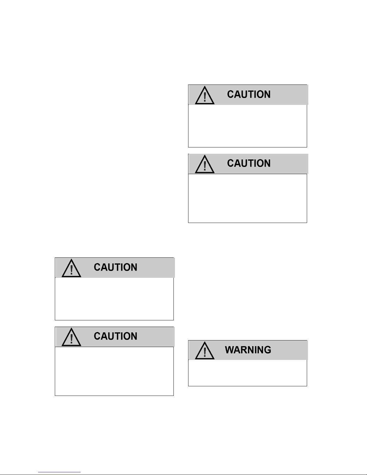
FUEL SYSTEM CAUTIONS
Do not smoke, carry lighted tobacco or
use a lighted flame of any type when
working on or near any fuel related
component. Highly flammable air-fuel
mixtures may be present and can be
ignited causing personal injury
Do not allow LPG to contact the skin.
LPG is stored in the fuel tank as a liquid. When LPG contacts the
atmosphere, it immediately expands
into a gas, resulting in a refrigeration
effect that can cause severe burns to
the skin.
Do not allow LPG to accumulate in
areas below ground level such as in a
service pit or underground ventilation
systems. LPG is heavier than air and
can displace oxygen, creating a dangerous condition
Do not make repairs to the LPG fuel
system if you are not familiar with or
trained to service LPG fuel system.
Contact the dealer who sold you the
vehicle to locate a repair facility with
trained technicians to repair your fuel
system
WARNINGS, CAUTIONS AND NOTES
This manual contains several different Warnings, Cautions, and Notes that must be
observed to prevent personal injury and or
damage to the vehicle, the fuel system or
personal property.
A “WARNING“ is an advisement that by performing a process or procedure listed in this
manual improperly may result in serious bodily injury, death and/or serious damage to the
vehicle or property.
Typical Warning Label:
Failure to heed instructions could result in death, injury, or property
damage.
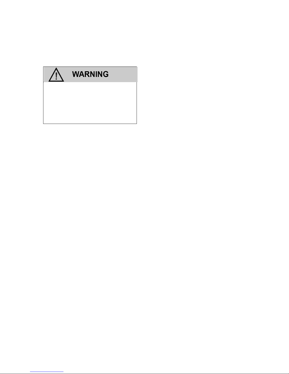
A “CAUTION” label or statement is used when
it has been determine that by performing a
process or procedure defined in the manual
improperly a less severe result may occur. It

GENERAL INFORMATION
8
could however, result in serious bodily injury,
and or serious damage to the vehicle or property damage.
Less severe than WARNING but has the
potential to cause injury or damage.
Also used to notify of situations that
could lead to eventual failure, injury or
damage.
This caution label may also appear in area of
this manual that applies to service and repair
procedures which could render the fuel and
emissions control system non-compliant. In
addition it may also be used to indicate a failure to observe which may influence the terms
of the warranty.
An “IMPORTANT” statement generally denotes a situation that requires strict
adherence to the assembly, tightening, or
service procedure. Failure to observe this
procedure could result in an unsafe condition
or improper performance of the vehicle or a
component.
A “NOTE” statement applies to a specific item
or procedure that is to be followed during the
servicing of the vehicle or its components.
PROPER USE OF THIS SERVICE MANUAL,
TOOLS AND EQUIPMENT
To reduce the potential for injury to the technician or others and to reduce damage to the
vehicle during service repairs the technician
should observe the following steps:
The service procedures defined in this
manual, when followed, have been found
to be a safe and efficient process to repair
the fuel system. In some cases special
tools may be required to perform the necessary procedures to safely remove and
replace a failed component.
The installed IMPCO fuel system has
been certified with the Environmental Protection Agency (EPA) and the California
Air Resources Board (CARB) and complies with the regulation in effect at the
time of certification. When servicing the
fuel and emission control system you
should follow all the recommended service and repair procedures to insure the
fuel and emissions system is operating as
designed and certified. Purposely or knowingly defeating or disabling any part or
the fuel and emission system may be in
violation of the anti-tampering provision of
the EPA’s Clean Air Act.
Tools identified in this manual with the
prefix “J” or “BT” can be procured through
SPX in Warren, Michigan.
Tools identified in this manual with a prefix
“ITK” can be acquired through OEM Parts
Distribution.
IMPORTANT
It is important to remember that there may be
a combination of Metric and Imperial fasteners used in the installation of the IMPCO fuel
system. Check to insure proper fit when using
a socket or wrench on any fastener to prevent
damage to the component being removed or
injury from “slipping off” the fastener.
The IMPCO fuels system utilizes fuel lines
hoses with swivel connections which attach to
fixed mating connectors. You should always
use a wrench of the proper size on both the
swivel and fixed fitting to prevent turning of
the fixed fitting. Turning of the fixed fitting may
cause a “twisting” or “kinking” of the hose and
may result in a restriction of the fuel line or a
leak.
GENERAL INFORMATION
9
Always leak check any fuel system
connection after servicing! Use an
electronic leak detector and/or a liquid
leak detection solution. Failure to leak
check could result in serious bodily
injury, death, or serious property damage.

10

11
Maintenance
12
MAINTENANCE
The maintenance of an engine and related components are critical to its operating performance
and lifespan. Industrial engines operate in environments that often include hot and cold
temperatures and extreme dust. The recommended maintenance schedule is listed in this
section, however, environmental operating conditions and additional installed equipment may
require more frequent inspection and servicing.
The owner and/or service agent should review the
operating conditions of the equipment to determine the inspection and maintenance intervals.
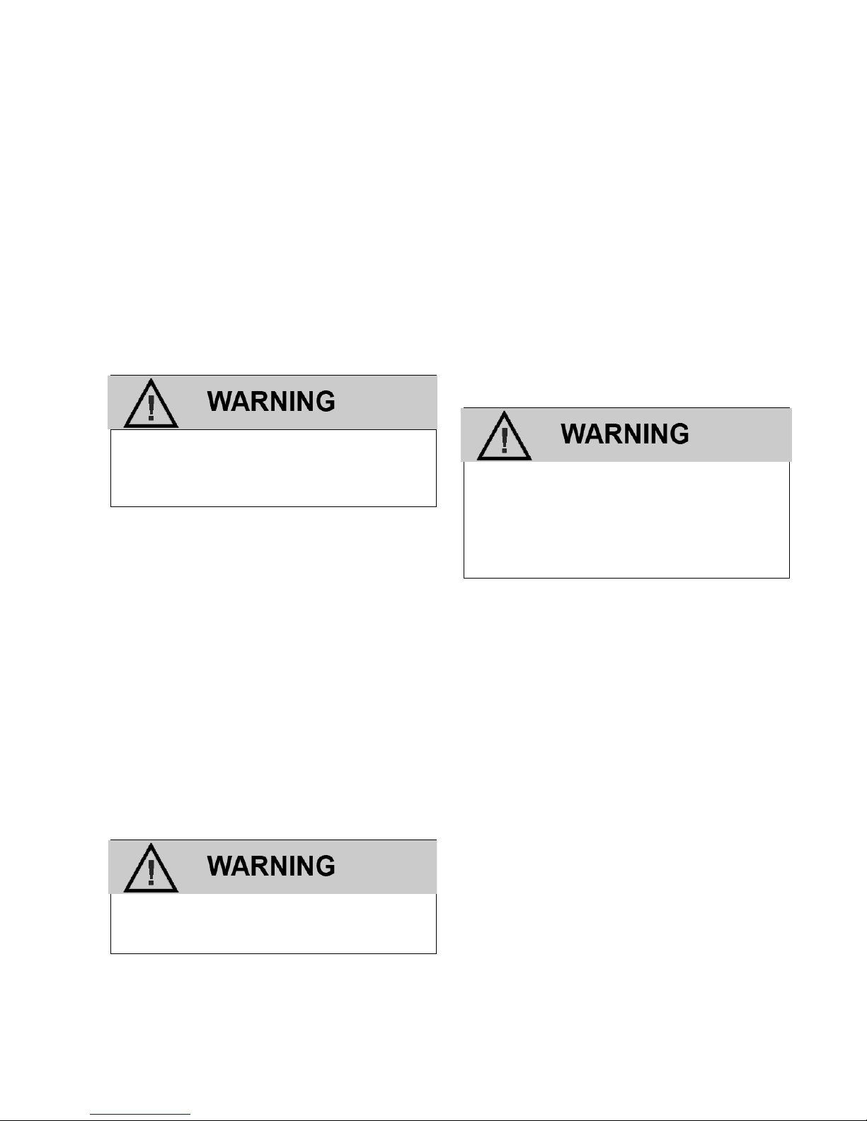
When performing maintenance on the engine,
turn the ignition OFF and disconnect the battery negative cable to avoid injury or damage
to the engine.
The engine installed in this equipment uses a serpentine drive belt con
figuration that drives the
water pump, alternator and additional pumps or
devices. It is important to note that the drive belt
is an integral part of the cooling and charging system and should be inspected according to the
maintenance schedule in this section. When inspecting the belts check for:
Cracks
Chunking of the belt
Splits
Material hanging loose from the belt
Glazing, hardening
If any of these conditions exist the belt should be
replaced with the recommended OEM replacement belt.
Alcohol or Methanol based anti-freeze or plain
water are not recommended for use in the
cooling system at anytime.
SERPENTINE BELT SYSTEM
Serpentine belts utilize a spring-loaded tensioner
to keep the belt properly adjusted. Serpentine
belts should be checked according to the maintenance schedule in this section.
IMPORTANT:
The use of “belt dressing” or “anti-slipping
agents” on belts is not recommended.
COOLING SYSTEM
It is important that the cooling system of the engine be maintained properly to ensure proper
performance and longevity.
Do not remove the cooling system pressure
cap (radiator cap) when the engine is hot.
Allow the engine to cool and then remove the
cap slowly to allow pressure to vent. Hot
coolant under pressure may discharge violently.
Note that the LPG vaporizer is connected to the
cooling system and the fuel system may be adversely affected by low coolant levels and
restricted or plugged radiator cores. Therefore,
the cooling system must be maintained according
to the recommend maintenance schedule in this
section and also include:
The regular removal of dust, dirt and debris
from the radiator core and fan shroud.
Inspection of coolant hoses and components
for leaks, especially at the radiator hose connections. Tighten hose clamps if necessary.
Check radiator hoses for swelling, separation,
hardening, cracks or any type of deterioration.
If any of these conditions exist the hose
should be replaced with a recommended OEM
replacement part.
Inspect the radiator cap to ensure proper seal-
ing.

13
COOLANT
Check coolant level in coolant recovery tank and
add coolant as required. Add 50/50 mixture of
ethylene glycol antifreeze and distilled water or
coolant per engine manufacturer’s instructions.
Do not add plain water. Replace coolant per the
recommended schedule.
IMPORTANT:
The manufacturers of the engine and fuel system
do not recommend the use of “stop leak” additives
to repair leaks in the cooling system. If leaks are
present the radiator should be removed and repaired or replaced.
ENGINE ELECTRICAL SYSTEM MAINTNANCE
The engine’s electrical system incorporates computers to control various related components. The
electrical system connections and ground circuits
require good connections. Follow the recommended maintenance schedule in this section to
maintain optimum performance. When inspecting
the electrical system check the following:
Check Positive and Negative cables for corro-
sion, rubbing, chafing, burning and to ensure
tight connections at both ends.
Check battery for cracks or damage to the
case and replace if necessary.
Inspect engine wire harness for rubbing, chaf-
ing, pinching, burning, and cracks or breaks in
the wiring.
Verify that engine harness connectors are cor-
rectly locked in by pushing in and then pulling
the connector halves outward.
Inspect primary ignition coil wires for harden-
ing, cracking, arcing, chafing, burning,
separation, split boot covers.
Check spark plug wires for hardening, crack-
ing, chafing, arcing or burning, separation, and
split boot covers.
Replace spark plugs at the required intervals
per the recommended maintenance schedule.
Verify that all electrical components are se-
curely mounted to the engine or chassis.
Verify that any additional electrical services
installed by the owner are properly installed in
the system.
Verify that the MIL, charging, and oil pressure
lights illuminate momentarily during engine start.
ENGINE CRANKCASE OIL
OIL RECOMMENDATION
Select an engine oil that will best match the prevailing daytime temperature:
Motor oils meeting this spec receive the API
(American Petroleum Institute) starburst symbol:
The recommended API classification: Above SG.
The oil capacity for the 2.0L engine including a
new filter is 1.1 gallons (4.0L)
IMPORTANT:
Oils recommended by the engine manufacturer
already contain a balanced additive treatment.
Oils containing “solid” additives, non-detergent
oils, or low quality oils are not recommended by
the engine manufacturer. The supplemental additives added to the engine oil are not necessary
and may be harmful. The engine and fuel system
14
supplier do not review, approve or recommend
such products.
SYNTHETIC OILS
Synthetic oils have been available for use in industrial engines for a relatively long period of
time and may offer advantages in cold and hot
temperatures. However, it is not known if synthetic oils provide operational or economic
bene
fits over conventional petroleum-based oils
in industrial engines. Use of synthetic oils does
not permit the extension of oil change intervals.
CHECKING/FILLING ENGINE OIL LEVEL
IMPORTANT:
Care must be taken when checking engine oil level. Oil level must be maintained between the
“ADD” mark and the “FULL” mark on the dipstick.
To ensure that you are not getting a false reading,
make sure the following steps are taken before
checking the oil level.
1. Stop engine.
2. Allow approximately five minutes for the oil to
drain back into the oil pan.
3. Remove the dipstick. Wipe with a clean cloth
or paper towel and reinstall. Push the dipstick
all the way into the dipstick tube.
4. Remove the dipstick and note the amount of
oil on the dipstick. The oil level must be between the “FULL” and “ADD” marks.
Figure 2 Engine Oil Dip tick (Typical)
5. If the oil level is below the “ADD” mark reinstall
the dipstick into the dipstick tube and proceed
to Step 6.
6. Remove the oil
filler cap from the valve cover.
7. Add the required amount of oil to bring the
level up to, but not over, the “FULL” mark on
the dipstick Reinstall the oil
filler cap to the
valve rocker arm cover and wipe any excess
oil clean.
CHANGING THE ENGINE OIL
IMPORTANT:
When changing the oil, always change the oil
filter.
1. Start the engine and run until it reaches normal operating temperature.
An overfilled crankcase (oil level being too
high) can cause an oil leak, a fluctuation or
drop in oil pressure. When overfilled, the engine crankshafts splash and agitate the oil,
causing it to aerate or foam.
IMPORTANT:
Change oil when engine is warm and the old oil
flows more freely.
2. Stop engine
IMPORTANT:
Engine oil will be hot. Use protective gloves to
prevent burns. Engine oil contains chemicals
which may be harmful to your health. Avoid skin
contact.
3. Remove drain plug and allow the oil to drain.
4. Remove and discard oil
filter and its sealing
ring.
5. Coat sealing ring on the new
filter with clean
engine oil, wipe the sealing surface on the
filter mounting surface to remove any dust, dirt
or debris. Tighten filter securely (follow filter
manufacturer’s instructions). Do not over tigh-
ten.
6. Check sealing ring on drain plug for any damage, replace if necessary, wipe plug with clean
rag, wipe pan sealing surface with clean rag
and re-install plug into the pan. Tighten to
25.3-32.4 ft.lbs (34.3-44.1 Nm).
IMPORTANT:
Always use a new drain plug gasket when changing the oil.
7. Fill crankcase with oil.
8. Start engine and check for oil leaks.

15
9. Dispose of oil and filter in a safe manner.
FUEL SYSTEM INSPECTION AND
MAINTENANCE
LPG FUEL SYSTEM
The LPG fuel system installed on this industrial
engine has been designed to meet the emission
standard applicable for the 2007-2009 model
years. To ensure compliance to these standards,
follow the recommended maintenance schedule
contained in this section.
INSPECTION AND MAINTENANCE OF THE
FUEL STORAGE CYLINDER
The fuel storage cylinder should be inspected
daily or at the beginning of each operational shift
for any leaks, external damage, adequate fuel
supply and to ensure the manual service valve is
open. Fuel storage cylinders should always be
securely mounted, inspect the securing straps or
retaining devices for damage ensure that all locking devices are closed and locked. Check to
ensure that the fuel storage cylinder is positioned
with the locating pin in the tank collar on all horizontally mounted cylinders this will ensure the
proper function of the cylinder relief valve.
When refueling or exchanging the fuel cylinder,
check the quick
fill valve for thread damage. Also
verify O-ring is in place and inspect for cracks,
chunking or separation. If damage to the o-ring
is found, replace prior to
filling. Check the ser-
vice line quick coupler for any thread damage.
IMPORTANT:
When refueling the fuel cylinder, wipe both the
female and male connection with a clean rag prior
to
filling to prevent dust, dirt and debris from being
introduced to the fuel cylinder.
INSPECTION AND REPLACEMENT OF THE
LPG FUEL FILTER
The LPG system on this emission certified engine
utilizes an in-line replaceable fuel filter element.
This element should be replaced, at the intervals
speci
fied in the recommended maintenance sche-
dule. When inspecting the fuel
filter check the
following:
Check for leaks at the inlet and outlet fittings,
using a soapy solution or an electronic leak
detector and repair if necessary.
Check to make sure filter is securely mounted.
Check filter housing for external damage or
distortion. If damaged replace fuel filter.
REPLACING THE LPG FUEL FILTER:
1. Move the equipment to a well ventilated area
and verify that sparks, ignition and any heat
sources are not present.
2. Start the engine.
3. Close the LPG tank valve.
4. When the engine stalls when it runs out of
fuel, turn the ignition key to the OFF position
and disconnect the battery negative cable.
IMPORTANT:
A small amount of fuel may still be present in the
fuel line. Use gloves and proper eye protection
to prevent burns. If liquid fuel continues to
flow
from the connections when removed, make sure
the manual valve is fully closed.
5. Slowly loosen the inlet
fitting and disconnect.
6. Slowly loosen the outlet fitting and disconnect.
7. Remove the filter housing form the equipment.
8. Check for contamination.
9. Tap the opening of the
filter on a clean cloth.
10. Check for debris.
11. Check canister for proper mounting direction.
12. Reinstall the
filter housing to the equipment.
13. Tighten the inlet and outlet fittings to specifica-
tion.
14. Open the LPG tank valve.
IMPORTANT:
The fuel cylinder manual valve contains an
Excess Flow Check Valve. Open the valve slowly
to prevent activating the Excess Flow Check
Valve.
15. Check for leaks at the inlet and outlet
fittings,
and the filter housing end connection using a
soapy solution or an electronic leak detector, if
leaks are detected make repairs.

16
ELECTRONIC PRESSURE REGULATOR (EPR)
MAINTENANCE AND INSPECTION
IMPORTANT:
The Electronic Pressure Regulator (EPR) components have been speci
fically designed and
calibrated to meet the fuel system requirements
of the emission certi
fied engine.
If the EPR fails to operate or develops a leak, it
should be repaired or replaced with the OEM
recommended replacement parts. When inspecting the regulator check for the following items:
Check for any fuel leaks at the inlet and outlet
fittings.
Check for any fuel leaks in the regulator body.
Check the inlet and outlet fittings of the coo-
lant supply lines for water leaks.
Check the coolant supply lines for hardening,
cracking, chafing or splits. If any of these conditions exist replace coolant lines.
Check coolant supply hose clamp connec-
tions, ensure they are tight.
Check to ensure the EPR is securely mounted
and the mounting bolts are tight.
Check EPR for external damage.
Check EPR electrical connection to ensure the
connector is seated and locked.
CHECKING/DRAINING OIL BUILD-UP IN THE
ELECTRONIC PRESSURE REGULATOR
During the course of normal operation oil or
“heavy ends” may build inside the secondary
chamber of the Electronic Pressure Regulator
(EPR). These oil and heavy ends may be a result
of poor fuel quality, contamination of the fuel, or
regional variation of the fuel make up. A significant build up of oil can affect the performance of
the secondary diaphragm response. The Recommended Maintenance Schedule found in this
section recommends that the oil be drained periodically. This is the minimum requirement to
maintain the emission warranty. More frequent
draining of the EPR is recommended for special
situation where substandard fuel may be a problem. IMPCO recommends the EPR be drained at
every engine oil change if contaminated or substandard fuel is suspected or known to have been
used or in use with the emission complaint fuel
system. This is known as special maintenance,
and failure to follow this recommendation may be
used to deny a warranty claim.
IMPORTANT:
Draining the regulator when the engine is warm
will help the oils to
flow freely from the regulator.
To drain the EPR, follow the steps below:
1. Move the equipment to a well ventilated area
and ensure no external ignition sources are
present.
2. Start the engine.
3. With the engine running close the LPG tank
valve.
4. When the engine runs out of fuel turn OFF the
key when the engine stops and disconnect the
negative battery cable.
IMPORTANT:
A small amount of fuel may still be present in the
fuel line, use gloves to prevent burns, wear proper eye protection. If liquid fuels continues to
flow
from the connections when loosened check to
make sure the manual valve is fully closed.
5. Slowly loosen the inlet
fitting and disconnect.
6. Loosen the hose clamp at the outlet hose
fitting and remove the hose.
7. Remove the Retaining Pin in the LPG Temperature Sensor and remove from the EPR
8. Remove the EPR mounting bolts.
9. Place a small receptacle in the engine compartment.
10. Rotate the EPR to 90° so that the outlet
fitting
is pointing down into the receptacle and drain
the EPR.
11. Inspect the secondary chamber for any large
dried particles and remove.
12. Remove the receptacle and reinstall the EPR
with the two retaining bolts and tighten to
speci
fications.
13. Reinstall the outlet fitting and secure with the
previously removed Retaining pin.
14. Reconnect the electrical connector (push in
until it clicks and securely locks), then pull on
the connector to ensure it is locked.
15. Connect the vacuum line.
16. Reconnect the outlet hose and secure the
hose clamp.
17. Reinstall the fuel inlet line and tighten connection to speci
fication.
18. Slowly open the LPG tank valve.

17
IMPORTANT:
The fuel cylinder manual valve contains an
Excess Flow Check Valve. Open the manual
valve slowly to prevent activating the Excess
Flow Check Valve.
19. Check for leaks at the inlet and outlet
fittings
using a soapy solution or an electronic leak
detector. If leaks are detected make repairs.
Check coolant line connections to ensure no
leaks are present.
20. Start engine recheck for leaks at the regulator.
21. Dispose of any drained material in safe and
proper manner.
AIR FUEL MIXER/THROTTLE CONTROL
DEVICE MAINTENANCE AND INSPECTION
IMPORTANT:
The Air Fuel Mixer components have been
speci
fically designed and calibrated to meet the
fuel system requirements of the emission certi
fied
engine. The mixer should not be disassembled or
rebuilt. If the mixer fails to operate or develops a
leak the mixer should be replaced with the OEM
recommended replacement parts.
When inspecting the mixer check for the following
items:
Leaks at the inlet fitting.
Fuel inlet hose for cracking, splitting or chaff-
ing, replace if any of these condition exist.
Ensure the mixer is securely mounted.
Inspect air inlet hose connection and clamp.
Also inspect inlet hose for cracking, splitting or
chafing. Replace if any of these conditions exist.
Inspect Air cleaner element according to the
Recommended Maintenance Schedule found
in this section.
Check Fuel lines for cracking, splitting or chaf-
ing. Replace if any of these conditions exist.
Verify Throttle Body return action to ensure
throttle shaft is not sticking. Repair if necessary.
Check for leaks at the Throttle Body and in-
take manifold.
EXHAUST SYSTEM AND CATALYTIC
CONVERTER INSPECTION AND
MAINTENANCE
IMPORTANT:
The exhaust system on this emission certi
fied engine contains a Heated Exhaust Gas Oxygen
Sensor (HEGO) which provides feed back to the
ECM on the amount of oxygen present in the exhaust stream after combustion.
The measurement of oxygen in the exhaust
stream is measured in voltage and sent to the
ECM. The ECM then makes corrections to the
fuel air ratio to ensure the proper fuel charge and
optimum catalytic performance. Therefore, it is
important that the exhaust connections remain
secured and air tight.
IMPORTANT:
The HEGO sensor is sensitive to silicone based
products. Do not use silicone sprays or hoses
which are assembled using silicone lubricants.
Silicone contamination can cause severe damage
to the HEGO.
When inspecting the Exhaust system check the
following:
Exhaust manifold at the cylinder head for
leaks and that all retaining bolts and shields (if
used) are in place.
Manifold to exhaust pipe fasteners to ensure
they are tight and that there are no exhaust
leaks repair if necessary.
HEGO electrical connector to ensure connec-
tor is seated and locked, check wires to
ensure there is no cracking, splits chafing or
“burn through.” Repair if necessary.
Exhaust pipe extension connector for leaks
tighten if necessary
Visually inspect converter to ensure muffler is
securely mounted and tail pipe is properly
aimed.
Check for any leaks at the inlet and outlet of
the converter.
18
LPG
& BI
-
FUEL
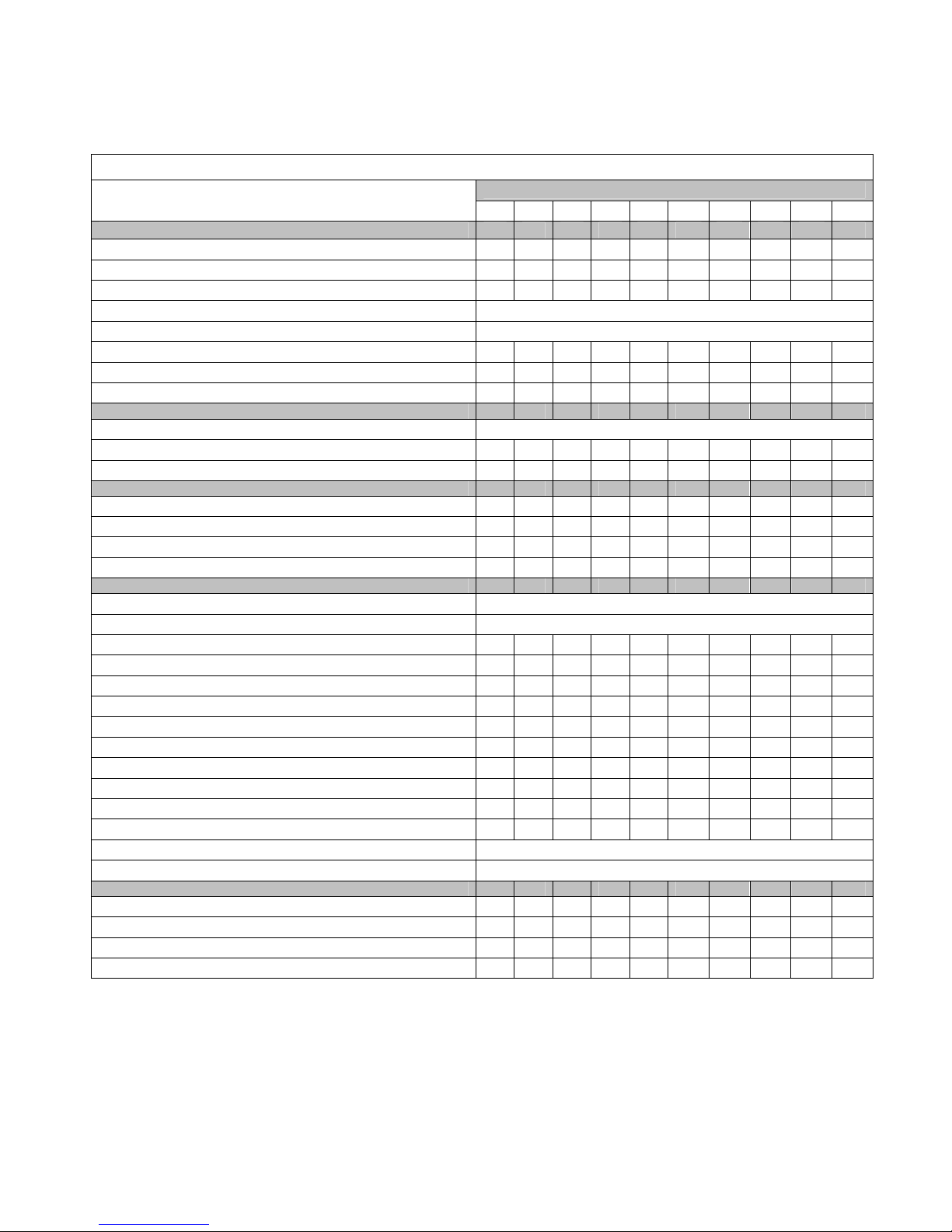
CERTIFIED ENGINE MAINTENANCE REQUIREMENTS
Perform the following maintenance on the engine at the hours indicated and at equivalent hour intervals thereafter.
Interval Hours
Daily 1000 1500 2000 2500 3000 3500 4000 4500 5000
General Maintenance Section
Visual check for fluid leaks
X
Check engine oil level
X
Check coolant level
X
Change engine oil and filter
Every 100 hours or 60 days of operation
Check LPG
system for leaks Prior to any service or maintenance activity
Inspect accessory drive belts for cracks, breaks, splits or glazing
X X X X X
Inspect
electrical system wiring for cuts, abrasions or corrosion X X
Inspect all vacuum lines and fittings for cracks, breaks or harden
ing X X
Engine Coolant Section
Clean debris from radiator core
Every 100 hours or 60 days of operation
Change coolant
X X X X X
Inspect coolant hoses for cracks, swelling or deterioration
X X X X X
Engine Ignition System
Inspect Battery case for leaks or damage
X X X X X
Inspect battery cables for damage corrosion or contamination
X X X X X
Check all electrical connector retainer locks
X X X X X
Replace spark plugs
X X
Fuel System Maintenance
Inspect air cleaner
Every 200 hours, or every 100 hours in dusty environment
Replace filter element
Annually, or Bi-annually in dusty environments
Replace PCV Valve
X
Replace inline LPG fuel filter
X X X X X
Check LPG shut off solenoid valve function
X X
Replace fuel filter
(Bi-fuel only) X X X X X
Inspect
Shut-off Valve for leaks and closing X X
Leak check
fuel lines X X
Check air induction for leaks
X X
Check manifold for
vacuum leaks X X
Check fuel injector s& rail for leaks (Bi-fuel only) X X
Replace fuel injectors (Bi-fuel only) X
Inspect
EPR for coolant leaks
Annually or every 2000 hours
Drain
EPR oil build up
Every 2500 hrs
Engine
Exhaust System
Inspect exhaust manifold for leaks
X X
Inspect exhaust piping for leaks
X X
Check HEGO sensor connector and wires for burns, cuts or damage
X X
Inspect catalyst for mechanical damage
X X
This maintenance schedule represents the manufacturer’s recommended maintenance intervals to maintain proper engine/equipment function. Federal, State, or Local regulations may require additional or more frequent inspection or maintenance
intervals than those specified above. Check with the authority having jurisdiction for details. Note that LPG engines are designed to
operate on HD–5 or HD–10 specification LPG fuel. Fuel other than HD–5 or HD–10 may cause harm to the engine’s emission
control system and a warranty claim may be denied on this basis if operators can readily find the proper fuel*. Use of any other fuel
may result in your engine no longer operating in compliance with CARB or EPA emissions requirements.
*Not Applicable in the state of California.

19
LPG Fuel System

20
LPG FUEL SYSTEM OPERATION
21
DESCRIPTION AND OPERATION OF THE FUEL
SYSTEMS
LPG FUEL SYSTEM
The primary components of the LPG fuel system
are the Fuel Storage Tank, Electronic Pressure
Regulator (EPR), Fuel Mixer, Throttle Control Device, electric Shut-Off Valve, Engine Control
Module (ECM), Oxygen Sensor and a Catalytic
Converter. The system operates at pressures which
range from 355.60mm (14.0 inches) of water column up to 21.5 BAR (312 psi).
LPG FUEL TANK
LPG is stored in the fuel tank as a liquid. The approximate pressure of the fuel in the tank is 8.8 bar
(130 psi) when the tank is full at an ambient temperature of 27° C (81°F). The boiling point,
(temperature at which the liquid fuel becomes vapor) is approximately 40° C (-40° F). When the fuel
changes from liquid to vapor the fuel expands and
creates pressure inside the tank. When the tank
service valve is opened the pressure inside the
tank forces the liquid fuel out though the pickup
tube located near the bottom of the fuel cylinder.
Because the LPG is stored under pressure the tank
is equipped with a safety valves which are normally
set at 25.8 bar (375 psi) to prevent tank rupture due
to over-pressurization of the cylinder. The service
valve mounted in the end of the cylinder controls
the
flow of fuel from the tank. By turning the handle
to its “open” position, fuel flows out of the tank and
into the service line. The service valve is also
equipped with a safety feature called an excess
flow check valve. This feature reduces the flow
from the service valve in the event of a rupture of
the fuel line or any downstream.
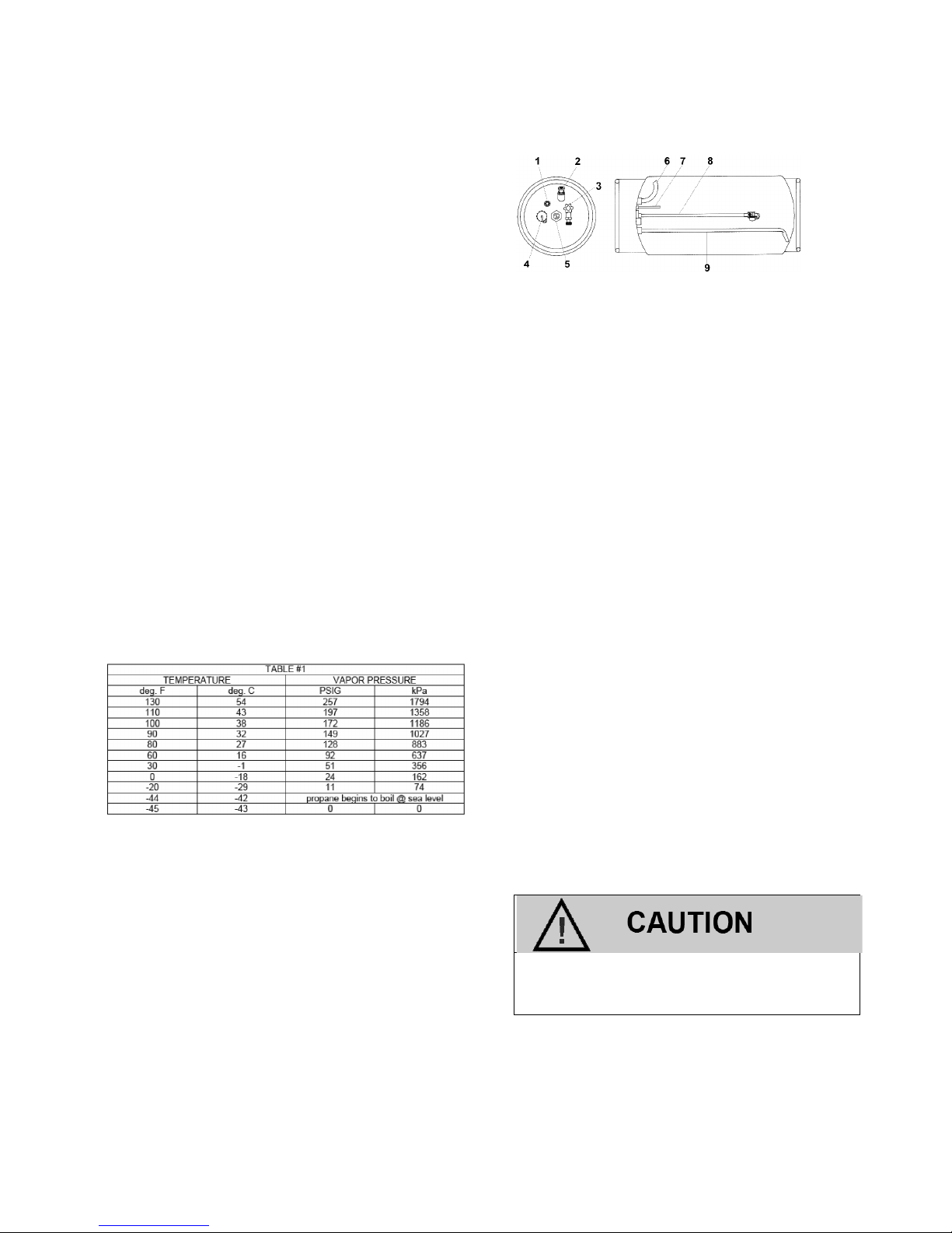
Typical LPG Cylinder
1. Liquid Outage Fill Check Valve
2. Pressure Relief Valve
3. Liquid Outage Valve w/quick disconnect coupling (also referred to as the manual shut-off
valve or MSV).
4. Filler Valve
5. Fuel Gauge
6. Vapor Withdrawal Tube (when applicable)
7. 80% Limiter Tube
8. Fuel Level Float
9. Liquid Withdrawal Tube
SERVICE LINE
LPG flows from the fuel tank to the electric LPG
Shut-Off Valve via the service line. The service
line is connected to the tank utilizing a quick
coupler. The other end of the service line is connected to a bulkhead connector mounted on the
equipment sheet metal. This bulkhead connector
allows for a safe means of passing through the
equipments engine compartment sheet metal and
into the engine compartment. If a bulkhead connector is used a pressure relief device is mounted
in the service line or the connector itself to prevent over pressurization. The service line is
made of high pressure hose with special material
or possibly tubing which is compatible with the
LPG fuel and should always be replaced with an
OEM supplied part.
The bulkhead assembly should never be
removed. Never run a service line through
the sheet metal.
22
FUEL FILTER
LPG, fuel like all other motor fuels is subject to
contamination from outside sources. Refueling of
the equipment tank and removal of the tank from
the equipment can inadvertently introduce dirt
and other foreign matter into the fuel system. It is
therefore necessary to
filter the fuel prior to entering the fuel system components downstream of
the tank. An inline fuel
filter has been installed in
the fuel system to remove the dirt and foreign
matter from the fuel, which is replaceable as a
unit only. Maintenance of the
filter is critical to
proper operation of the fuel system and should be
replaced according to the maintenance schedule
or more frequently under severe operating conditions.
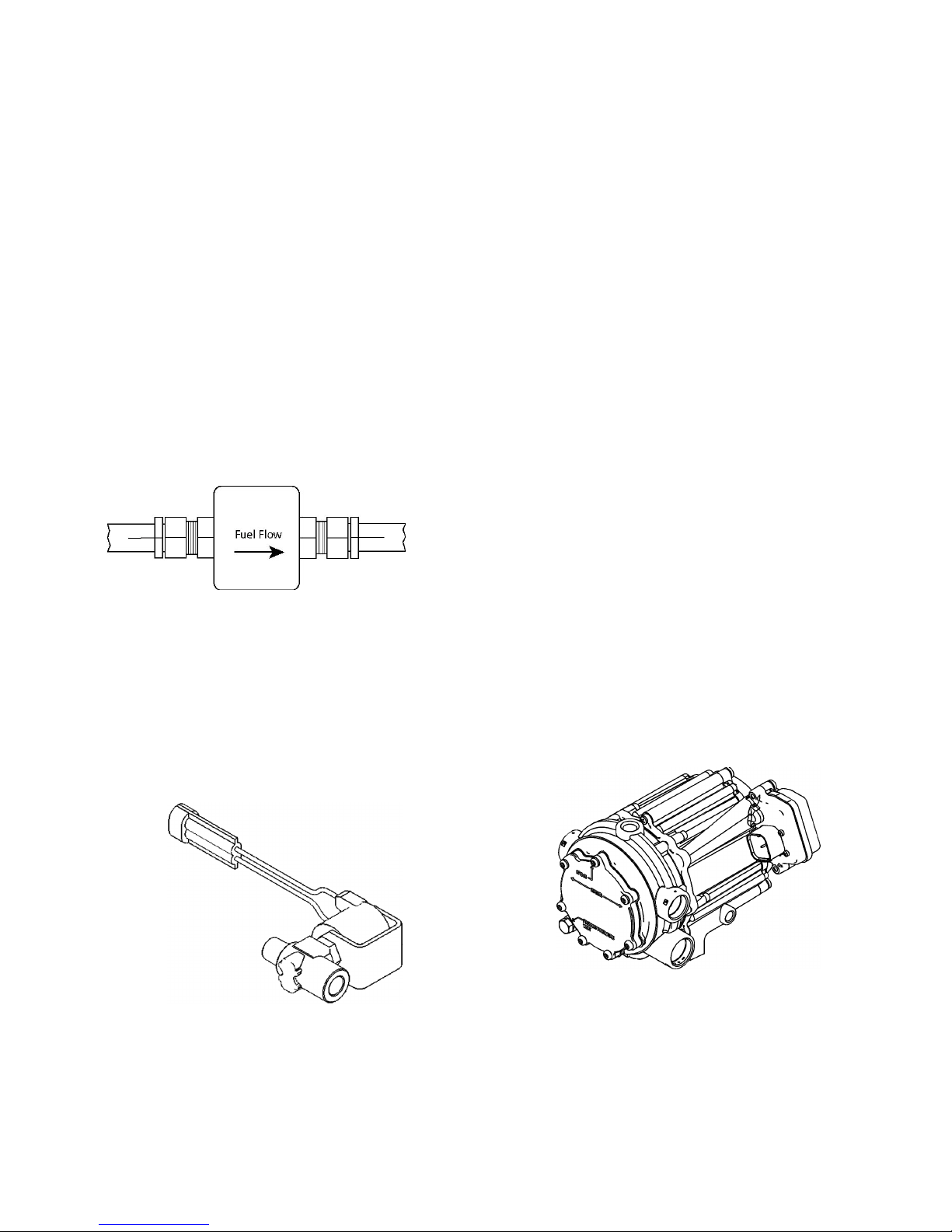
Inline Fuel Filter
LPG SHUT-OFF VALVE
The LPG Shut-Off Valve is an integrated assembly
consisting of a 12 volt solenoid and a normally
closed valve. When energized, the solenoid opens
the valve and allows the LPG fuel to
flow through
the device. The valve opens during cranking and
engine run cycles.
LPG Shut-Off Valve
Voltage to the LPG Shut-Off Valve is controlled by
the engine control module (ECM).
ELECTRONIC PRESSURE REGULATOR (EPR)
The EPR is a combination vaporizer and pressure
regulating device. The EPR functions as a negative pressure two stage regulator that is normally
closed with the ability to supply additional fuel by
command from the ECM. When the engine is
cranking or running, a partial vacuum is created
in the fuel line which connects the regulator to the
mixer. This partial vacuum opens the regulator
permitting fuel to
flow to the mixer.
LPG fuel enters the primary port of the EPR and
passes through the primary jet and into the primary/heat exchanger chamber and expands as it
heats up, creating pressure inside the chamber.
When the pressure increases above 10.34 kPa
(3.5 psi), sufficient pressure is exerted on the
primary diaphragm to cause the diaphragm plate
to pivot and press against the primary valve pin,
thus closing off the
flow of fuel. When the engine
is cranking, sufficient vacuum will be introduced
into the secondary chamber from the mixer drawing the secondary diaphragm down onto the
spring loaded lever and opening the secondary
valve. An increase in vacuum in the secondary
chamber increases the downward action on the
secondary lever, causing it to open wider and
permitting more fuel
flow to the mixer.
Electronic Pressure Regulator
23
The EPR is an emission control device
and should only be serviced by qualified
technicians.
AIR FUEL MIXER
The air valve mixer is a completely self-contained
air-fuel metering device. The mixer is an air valve
design, utilizing a relatively constant pressure drop
to draw fuel into the mixer from cranking to full load.
The mixer is mounted in the air stream ahead of the
throttle control device.
When the engine begins to crank it draws in air with
the air valve covering the inlet, and negative pressure begins to build. This negative pressure signal
is communicated to the top of the air valve chamber
through 4 vacuum ports in the air valve assembly.
A pressure/force imbalance begins to build across
the air valve diaphragm between the air valve vacuum chamber and the atmospheric pressure
below the diaphragm. The air valve vacuum spring
is calibrated to generate from 101.6 mm (4.0 inches) of water column at start to as high as 355.60
mm (14.0 inches) of water column at full throttle.
The vacuum being created is referred to as Air
Valve Vacuum (AVV). As the air valve vacuum
reaches 101.6mm (4.0 inches) of water column, the
air valve begins to lift against the air valve spring.
The amount of AVV generated is a direct result of
the throttle position. At low engine speed the air
valve vacuum and the air valve position is low thus
creating a small venturi for the fuel to
flow. As the
engine speed increases the AVV increases and the
air valve is lifted higher thus creating a much larger
venturi. This air valve vacuum is communicated
from the mixer venturi to the EPR secondary
chamber via the low pressure fuel supply hose. As
the AVV increases in the secondary chamber the
secondary diaphragm is drawn further down forcing
the secondary valve lever to open wider.
The mixer is equipped with a low speed mixture
adjustment retained in a tamper proof housing.
The mixer has been preset at the factory and
should not require adjustment. In the event that the
idle adjustment should need to be adjusted refer to
the Fuel System Repair section of this manual.
The air/fuel mixer is an emission control
device. Components inside the mixer are
specifically calibrated to meet the engine’s
emissions requirements and should never
be disassembled or rebuilt. If the mixer
fails to function correctly, replace with an
OEM replacement part.
THROTTLE CONTROL DEVICE—DRIVE BY
WIRE
Drive By Wire Engine speed control is maintained
by the amount of pressure applied to the foot
pedal located in the engine compartment. In a
Drive By Wire (DBW) application, there is no direct connection between the operator pedal and
the throttle shaft. Speed and load control are determined by the ECM. Defaults programmed into
the ECM software and throttle position sensors
allow the ECM to maintain safe operating control
over the engine. In a drive by wire application the
Electronic Throttle Control device or throttle body
assembly is connected to the intake manifold of
the engine. The electronic throttle control device
utilizes an electric motor connected to the throttle
shaft. In addition, a Foot Pedal Position sensor
(FPP) is located in the operator’s compartment.
When the engine is running electrical signals are
sent from the foot pedal position sensor to the
engine ECM when the operator depresses or release the foot pedal. The ECM then sends an
electrical signal to the motor on the electronic
throttle control to increase or decrease the angle
of the throttle blade thus increasing or decreasing
the air/fuel charge to the engine. The electronic
throttle control device incorporates two internal
Throttle Position Sensors (TPS) which provide
output signals to the ECM as to the location of the
throttle shaft and blade. The TPS information is
used by the ECM to correct for speed and load
control as well as emission.

24
CATALYTIC CONVERTER
The Catalytic Converter is a component of the
emissions system which is designed and calibrated to meet the emission standards in effect
for 2007-2009 model year.
The exhaust gases pass through the honeycomb
catalyst which is coated with a mixture of metals
(such as platinum, palladium, and rhodium) to
oxidize and reduce CO, HC and NOX emission
gases.
Catalytic Converter/Muffler
ENGINE CONTROL MODULE
To obtain maximum effect from the catalyst and
accurate control of the air fuel ratio, the emission
certi
fied engine is equipped with an onboard
computer or Engine Control Module (ECM). The
ECM is a 32 bit controller which receives input
data from sensors mounted to the engine and fuel
system and then outputs various signals to control engine operation.
Engine Control Module (ECM)
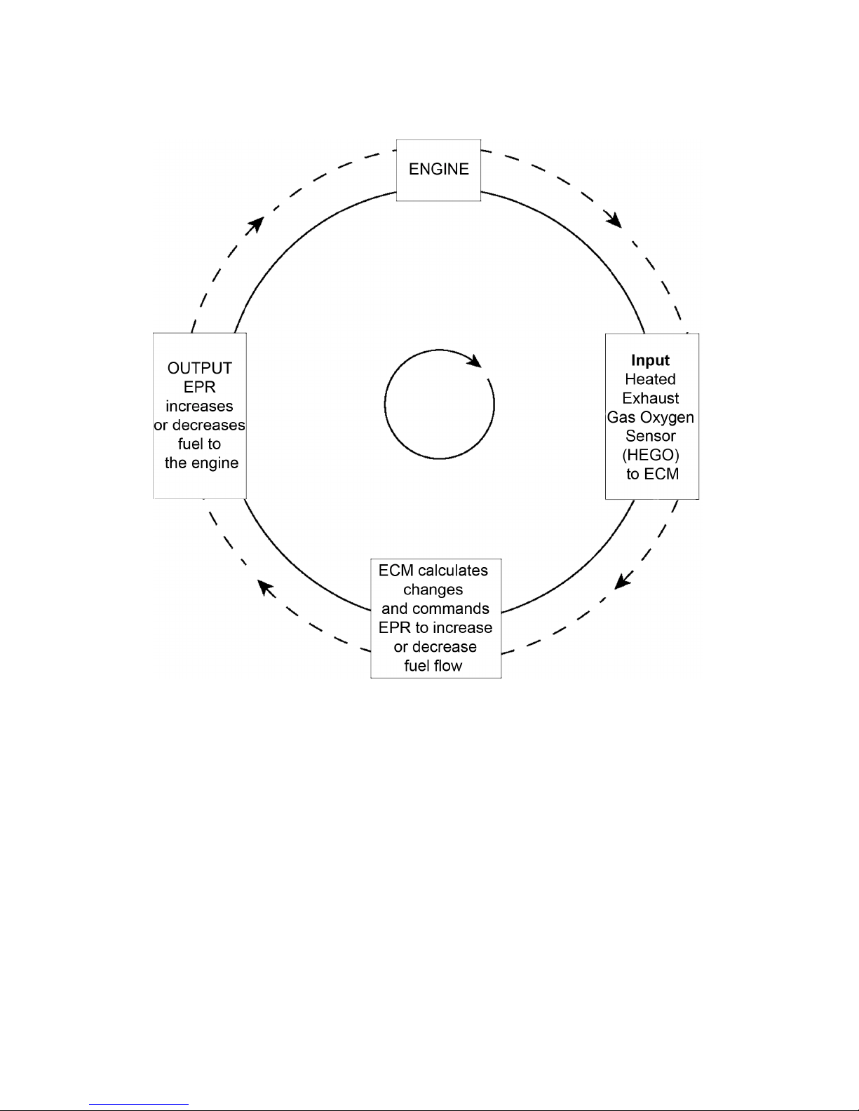
One specific function of the controller is to maintain a closed loop fuel control which is
accomplished by use of the Heated Exhaust Gas
Oxygen sensor (HEGO) mounted in the exhaust
system. The HEGO sensor sends a voltage signal to the controller which then outputs signals to
the EPR to change the amount of fuel being delivered from the regulator or mixer to the engine.
The controller also performs diagnostic functions
on the fuel system and noti
fies the operator of
engine malfunctions by turning on a Malfunction
Indicator Light (MIL) mounted in the dash. Malfunctions in the system are identi
fied by a
Diagnostic Trouble Code (DTC) number. In addition to notifying the operator of the malfunction in
the system, the controller also stores the information about the malfunction in its memory. A
technician can than utilize a computerized diagnostic scan tool to retrieve the stored diagnostic
code and by using the diagnostic charts in this
manual to determine the cause of the malfunction. In the event a technician does not have the
computerized diagnostic tool, the MIL light can be
used to identify the diagnostic code to activate
the “blink” feature and count the number of blinks
to determine the diagnostic code number to locate the fault in the system.
HEATED EXHAUST GAS OXYGEN SENSORS
The Heated Exhaust Gas Oxygen (HEGO) Sensors are mounted in the exhaust system, one
upstream and one downstream of the catalytic
converter. The HEGO sensors are used to
measure the amount of oxygen present in the exhaust stream to determine whether the fuel air
ratio is to rich or to lean. It then communicates
this measurement to the ECM. If the HEGO sensor signal indicates that the exhaust stream is too
rich, the ECM will decrease or lean the fuel mixture during engine operation. If the mixture is too
lean, the ECM will richen the mixture. If the ECM
determines that a rich or lean condition is present
for an extended period of time which cannot be
corrected, the ECM will set a diagnostic code and
turn on the MIL light in the dash.
By monitoring output from the sensor upstream
and the sensor downstream of the catalytic converter, the ECM can determine the performance
of the converter.
25
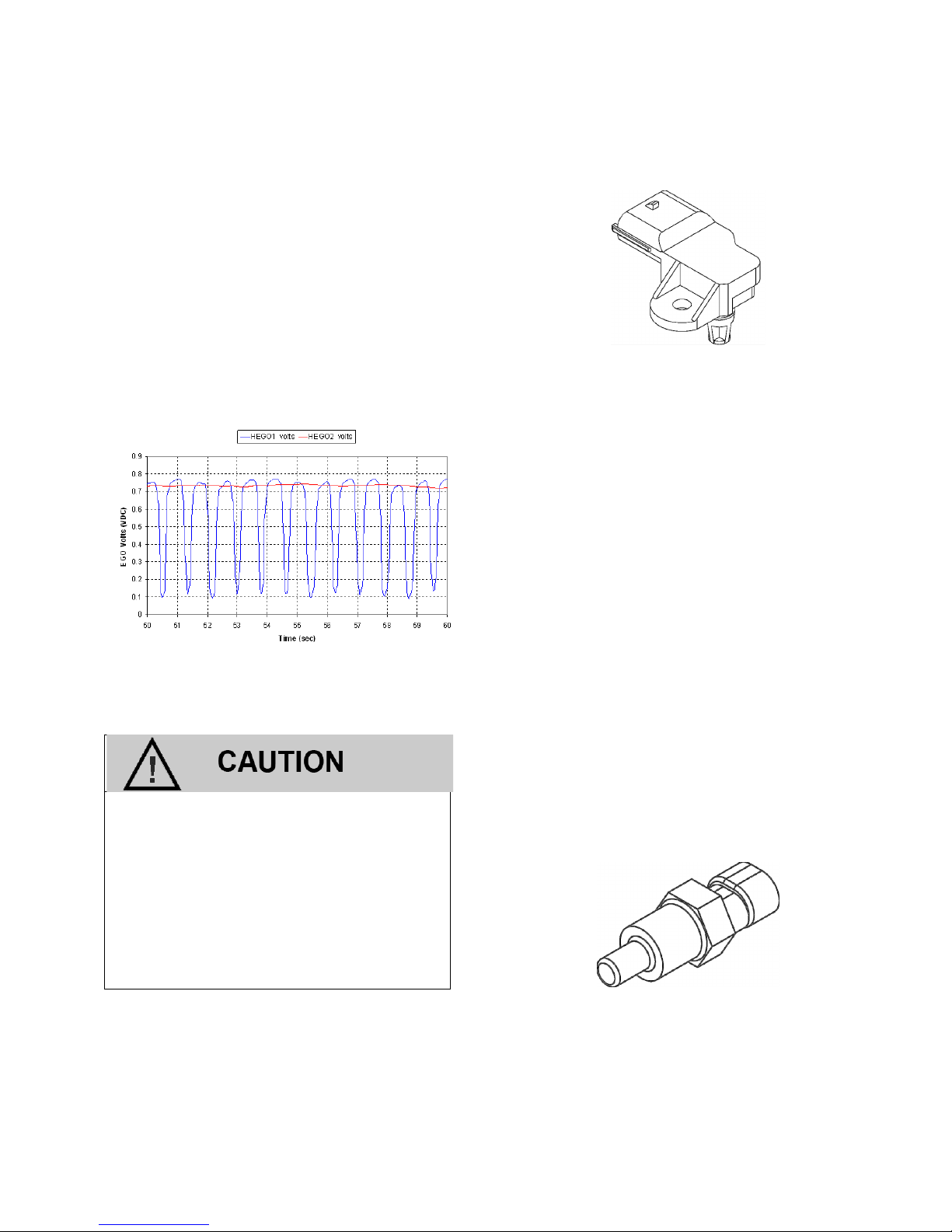
The Heat Exhaust Gas Oxygen (HEGO) Sensor
HEGO1 (upstream or before the catalytic converter) and HEGO2 (downstream) voltage
output.
The Heated Exhaust Gas Oxygen Sensor
(HEGO) is an emissions control component. In the event of a failure, the HEGO
should only be replaced with the recommended OEM replacement part. The
HEGO is sensitive to silicone based products and can become contaminated.
Avoid using silicone sealers or air or fuel
hoses treated with a silicone based lubricant.
TMAP SENSOR
T–MAP Sensor
The Air Temperature/Manifold Absolute Pressure
or TMAP sensor is a combination of two sensors:
1) A variable resistor used to monitor the differ-
ence in pressure between the intake manifold
and outside or atmospheric pressure. The
ECM monitors the resistance of the sensor to
determine engine load (the vacuum drops
when the engine is under load or at wide
open throttle). When the engine is under load,
the computer may alter the fuel mixture to improve performance and emissions.
2) The intake air temperature or IAT sensor is a
variable resistance thermistor located in the air
intake passage which measures the temperature of the incoming air. The ECM uses the
resistance value to monitor incoming air temperature and calculate the engine’s airflow
requirement. The ECM provides a voltage divider circuit so that when the air is cool, the
signal reads a higher voltage, and lower when
warm. On cold starts, the ECM richens the
fuel/air mixture.
COOLANT TEMPERATURE SENSOR
ECT
The Engine Coolant Temperature sensor or ECT
is a variable resistance thermistor that changes
resistance as the engine's coolant temperature
26
changes. The sensor's output is monitored by
the ECM to determine a cold start condition and
to regulate various fuel and emission control
functions via a closed loop emission system.
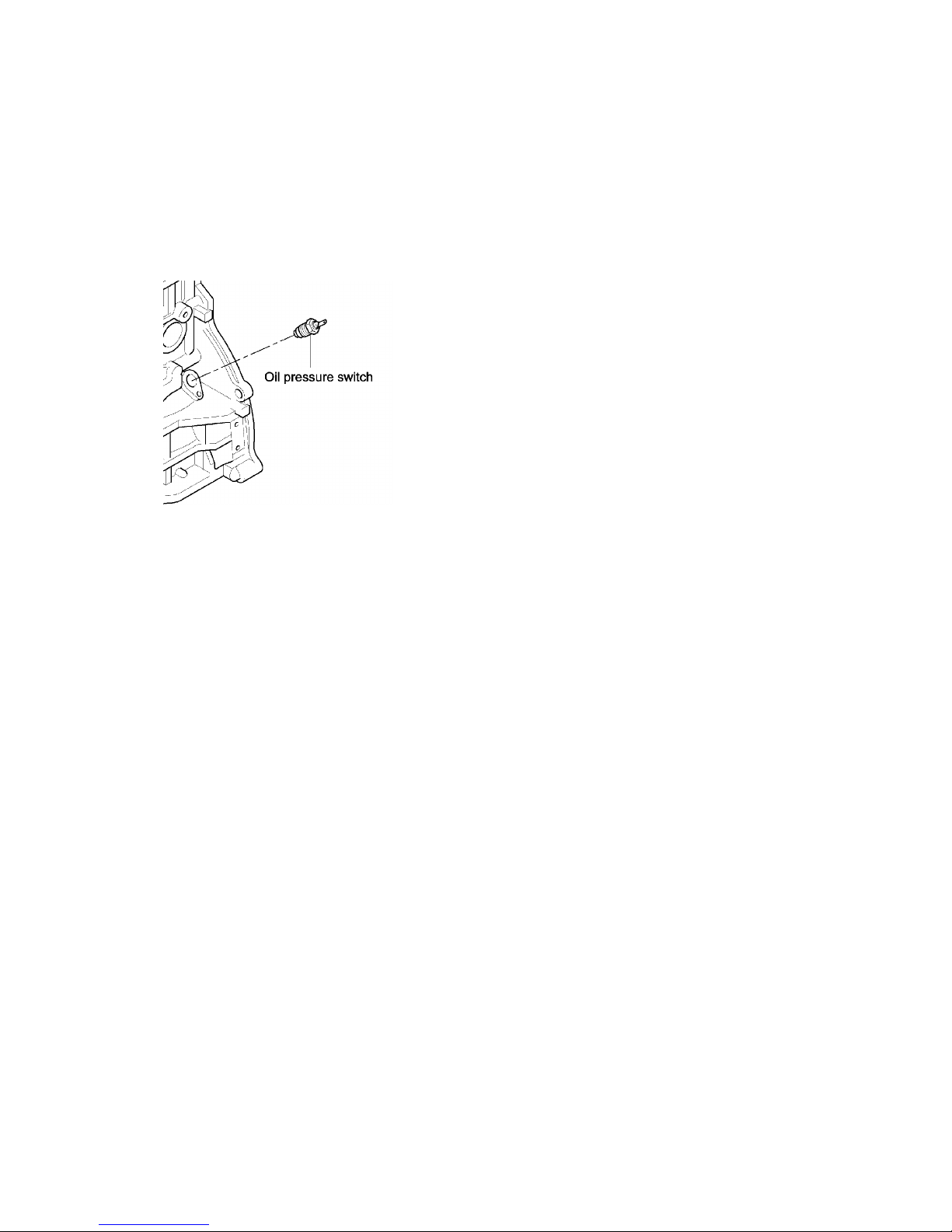
OIL PRESSURE SENDER/SWITCH
The Oil Pressure Switch is Mounted on the
side of the Engine Block
The Engine Oil Pressure switch or sender is designed to ensure adequate lubrication throughout
the engine. It provides a pressure value for the
oil pressure gauge and is monitored by the ECM.
If the pressure drops, an MIL will occur.
27
LPG Closed Loop Schematic

28

29
LPG System Diagnosis

30
LPG FUEL SYSTEM DIAGNOSIS
The Electronic Pressure Regulator Assembly (EPR), Shown with Port Fittings and Shut-off Valve.
FUEL SYSTEM DESCRIPTION
The Engine Control Module (ECM) receives information from various engine sensors in order
to control the operation of the Electronic Pressure Regulator (EPR) and Shut-Off Valve. The
Shut-Off Valve solenoid prevents fuel
flow un-
less the engine is cranking or running.
LPG is stored in the tank as a liquid and delivered under pressure of up to 21.5 BAR (312
psi). At Key ON, the EPR receives a two (2)
second prime pulse from the ECM, allowing
time for the LPG to
flow from the tank through
the fuel
filter and fuel lines to the EPR. Inside of
the EPR, fuel is vaporized and reduced in pressure in two stages. The
first stage reduces the
tank pressure to approximately 20.68 kilopascals (3.0 psi). The second stage then reduces
the pressure to approximately negative 38.1
mm (1.5” of water column) when vacuum from
the engine draws in fuel.
The fuel is then drawn in from the secondary
chamber of the EPR by the vacuum generated
by air
flowing through the Mixer. This vacuum
is also generates lift for the mixer air valve and
is commonly referred to as air valve vacuum.
Once in the mixer, the fuel is combined with air
and is drawn into the engine for combustion.
DIAGNOSTIC AIDS
This procedure is intended to diagnose a vehicle operating on LPG. If the vehicle will not
continue to run on LPG, refer to Hard Start for
preliminary checks. Before starting this proce-
dure, complete the following tasks to verify that
liquid fuel is being delivered to the EPR:
Inspect fuel tank to verify it has a sufficient
amount of fuel.
Verify manual shut off valve on the LPG
tank is fully opened.
Verify that the excess flow valve has not
been activated.
Inspect fuel tank to ensure it is properly
mounted and rotated to the correct position.
Inspect the hoses leading from the tank en-
suring they are properly connected and do
not have any kinks or damage.
 Loading...