

Impassa SCW9055D-433, SCW9055G-433, SCW9055I-433, SCW9055D-868, SCW9055G-868 User Manual
...
Self Contained Wireless Alarm System
WWW.DIYALARMFORUM.COM
Models:
SCW9055(D)(G)(I)-433/868
SCW9057(D)(G)(I)-433/868
Used with:
WT5500-433/868
WT5500(P)-433/868
v1.0 Installation Guide
WARNING: This manual contains information on limitations regarding product use and
function and information on the limitations as to liability of the manufacturer. The entire
manual should be carefully read.

WWW.DIYALARMFORUM.COM

Table of Contents
WWW.DIYALARMFORUM.COM
1 Introduction. . . . . . . . . . . . . . . . . . . . . . . . . . . . . . . . . . . . . . . . . . . . . . . . . . . . . . . . . . . . 1
1.1 SCW9055/57 Model Differences . . . . . . . . . . . . . . . . . . . . . . . . . . . . . . . . . . . . . . . . . . . . . . . . . . . . . . . . . . . . . . . . . . 1
1.2 Compatible Wireless Devices . . . . . . . . . . . . . . . . . . . . . . . . . . . . . . . . . . . . . . . . . . . . . . . . . . . . . . . . . . . . . . . . . . . . 1
1.3 Product Specifications . . . . . . . . . . . . . . . . . . . . . . . . . . . . . . . . . . . . . . . . . . . . . . . . . . . . . . . . . . . . . . . . . . . . . . . . . . 2
1.4 Controls & Indicators . . . . . . . . . . . . . . . . . . . . . . . . . . . . . . . . . . . . . . . . . . . . . . . . . . . . . . . . . . . . . . . . . . . . . . . . . . . 3
1.5 Data Entry . . . . . . . . . . . . . . . . . . . . . . . . . . . . . . . . . . . . . . . . . . . . . . . . . . . . . . . . . . . . . . . . . . . . . . . . . . . . . . . . . . . 3
2 Installation . . . . . . . . . . . . . . . . . . . . . . . . . . . . . . . . . . . . . . . . . . . . . . . . . . . . . . . . . . . . 5
2.1 Mounting . . . . . . . . . . . . . . . . . . . . . . . . . . . . . . . . . . . . . . . . . . . . . . . . . . . . . . . . . . . . . . . . . . . . . . . . . . . . . . . . . . . . 5
2.2 Wiring. . . . . . . . . . . . . . . . . . . . . . . . . . . . . . . . . . . . . . . . . . . . . . . . . . . . . . . . . . . . . . . . . . . . . . . . . . . . . . . . . . . . . . . 6
2.3 Wireless Device Setup. . . . . . . . . . . . . . . . . . . . . . . . . . . . . . . . . . . . . . . . . . . . . . . . . . . . . . . . . . . . . . . . . . . . . . . . . . 7
2.4 Alternate Communicator Module Setup/Initialization . . . . . . . . . . . . . . . . . . . . . . . . . . . . . . . . . . . . . . . . . . . . . . . . . . . 9
3 Operation . . . . . . . . . . . . . . . . . . . . . . . . . . . . . . . . . . . . . . . . . . . . . . . . . . . . . . . . . . . . 10
3.1 Operating Modes . . . . . . . . . . . . . . . . . . . . . . . . . . . . . . . . . . . . . . . . . . . . . . . . . . . . . . . . . . . . . . . . . . . . . . . . . . . . . 10
3.2 Language Selection . . . . . . . . . . . . . . . . . . . . . . . . . . . . . . . . . . . . . . . . . . . . . . . . . . . . . . . . . . . . . . . . . . . . . . . . . . . 10
3.3 [ ✱ ] Commands. . . . . . . . . . . . . . . . . . . . . . . . . . . . . . . . . . . . . . . . . . . . . . . . . . . . . . . . . . . . . . . . . . . . . . . . . . . . . . 10
3.4 Function Keys . . . . . . . . . . . . . . . . . . . . . . . . . . . . . . . . . . . . . . . . . . . . . . . . . . . . . . . . . . . . . . . . . . . . . . . . . . . . . . . 13
3.5 System Removal Prevention . . . . . . . . . . . . . . . . . . . . . . . . . . . . . . . . . . . . . . . . . . . . . . . . . . . . . . . . . . . . . . . . . . . . 13
4 Programming . . . . . . . . . . . . . . . . . . . . . . . . . . . . . . . . . . . . . . . . . . . . . . . . . . . . . . . . . 14
4.1 Template Programming . . . . . . . . . . . . . . . . . . . . . . . . . . . . . . . . . . . . . . . . . . . . . . . . . . . . . . . . . . . . . . . . . . . . . . . . 14
4.2 DLS Programming . . . . . . . . . . . . . . . . . . . . . . . . . . . . . . . . . . . . . . . . . . . . . . . . . . . . . . . . . . . . . . . . . . . . . . . . . . . . 17
4.3 Installer Programming . . . . . . . . . . . . . . . . . . . . . . . . . . . . . . . . . . . . . . . . . . . . . . . . . . . . . . . . . . . . . . . . . . . . . . . . . 17
5 Advanced Programming. . . . . . . . . . . . . . . . . . . . . . . . . . . . . . . . . . . . . . . . . . . . . . . . . 18
5.1 How to Program. . . . . . . . . . . . . . . . . . . . . . . . . . . . . . . . . . . . . . . . . . . . . . . . . . . . . . . . . . . . . . . . . . . . . . . . . . . . . . 18
5.2 Index to Programming Worksheets and Descriptions . . . . . . . . . . . . . . . . . . . . . . . . . . . . . . . . . . . . . . . . . . . . . . . . . 19
5.3 Programming Worksheets . . . . . . . . . . . . . . . . . . . . . . . . . . . . . . . . . . . . . . . . . . . . . . . . . . . . . . . . . . . . . . . . . . . . . . 20
5.4 Programming Descriptions. . . . . . . . . . . . . . . . . . . . . . . . . . . . . . . . . . . . . . . . . . . . . . . . . . . . . . . . . . . . . . . . . . . . . . 40
6 Testing and Troubleshooting . . . . . . . . . . . . . . . . . . . . . . . . . . . . . . . . . . . . . . . . . . . . . 67
Appendix A: Reporting Code Formats. . . . . . . . . . . . . . . . . . . . . . . . . . . . . . . . . . . . . . . . 70
Appendix B: 2-Way Audio Verification (SCW9057 only) . . . . . . . . . . . . . . . . . . . . . . . . . . 73
Appendix C: Communicator Format Options. . . . . . . . . . . . . . . . . . . . . . . . . . . . . . . . . . . 74
Appendix D: Regulatory Approvals Information . . . . . . . . . . . . . . . . . . . . . . . . . . . . . . . . 75

SAFETY INSTRUCTIONS for SERVICE PERSONNEL
WWW.DIYALARMFORUM.COM
WARNING: When using equipment connected to the TELEPHONE NETWORK, there are basic safety instructions that should always
be followed. Refer to the SAFETY INTRUCTIONS provided with this product; save them for (future) reference. Instruct the end-user
regarding the safety precautions that shall be observed when operating this equipment.
Before Installing The Equipment
Ensure your package includes the following items:
• Installation and User Manuals, including the SAFETY INSTRUCTIONS.
READ and SAVE These Instructions!
Follow All WARNINGS AND INSTRUCTIONS specified within this document and/or on the equipment
• SCW905x alarm controller
• Power Supply, direct plug-in
• Mounting hardware
Selecting A Suitable Location For The Alarm Controller
Use the following list as a guide to find a suitable place for this equipment:
• Locate near a telephone socket and power outlet.
• Select a place free from vibration and shocks.
• Place the alarm controller on a flat, stable surface and follow the installation Instructions.
DO NOT locate this product where persons may walk on the secondary circuit cable(s).
DO NOT connect the alarm controller to electrical outlets on the same circuit as large appliances.
DO NOT select a place that exposes your alarm controller to direct sunlight, excessive heat, moisture, vapors, chemicals or dust.
DO NOT install this equipment near water. (e.g., bath tub, wash bowl, kitchen/laundry sink, wet basement, near a swimming
pool).
DO NOT install this equipment and its accessories in areas where there is a risk of explosion.
DO NOT connect this equipment to electrical outlets controlled by wall switches or automatic timers;
AV O I D interference sources.
AV O I D setting up the equipment near heaters, air conditioners, ventilators, and/or refrigerators.
AV O I D locating this equipment close to or on top of large metal objects (e.g., metal wall studs).
SAFETY Precautions Required During Installation
• NEVER install this equipment and/or telephone wiring during a lightning storm.
• NEVER touch uninsulated telephone wires or terminals unless the telephone line has been disconnected at the network interface.
• Position cables so that accidents can not occur. Connected cables must NOT be subject to excessive mechanical strain.
• Use only the power supply provided with this equipment. Use of unauthorized power supplies may cause damage.
• For direct plug-in versions, use the transformer supplied with the device.
WARNING:
THIS EQUIPMENT HAS NO MAINS ON/OFF SWITCH. THE PLUG OF THE DIRECT PLUG-IN POWER SUPPLY IS
INTENDED TO SERVE AS THE DISCONNECTING DEVICE IF THE EQUIPMENT MUST BE QUICKLY DISCONNECTED. IT
IS IMPERATIVE THAT ACCESS TO THE MAINS PLUG AND ASSOCIATED MAINS SOCKET/OUTLET IS NEVER
OBSTRUCTED.
IMPORTANT NOTE!
This Alarm System shall be installed and used within an
environment that provides the pollution degree max 2 and overvoltages category II NON-HAZARDOUS LOCATIONS, indoor
only. The equipment is DIRECT PLUG-IN (external transformer)
and is designed to be installed, serviced and/or repaired by
service persons only; [service person is defined as a person
having the appropriate technical training and experience
necessary to be aware of hazards to which that person may be
exposed in performing a task and of measures to minimize the
risks to that person or other persons]. There are no parts
replaceable by the end-user within this equipment. The wiring
(cables) used for installation of the Alarm System and
accessories, shall be insulated with PVC, TFE, PTFE, FEP,
Neoprene or Polyamide.
(a) The equipment enclosure must be secured to the building
structure before operation.
(b) Internal wiring must be routed in a manner that prevents:
- Excessive strain or loosening of wire on terminal
connections;
- Damage of conductor insulation
(c) Disposal of used batteries shall be made in accordance
with local waste recovery and recycling regulations.
(d) Before servicing, DISCONNECT the power and telephone
connection.
(e) DO NOT route any wiring over circuit boards.
(f) It is the installer’s responsibility to ensure that a readily
accessible disconnect device is incorporated in the building
for permanently connected installations.
The power supply must be Class II, FAIL SAFE with double or reinforced insulation between the PRIMARY and SECONDARY circuit/
ENCLOSURE and be an approved type acceptable to the local authorities. All national wiring rules shall be observed.
i
Guidelines for Locating Smoke & CO Detectors
WWW.DIYALARMFORUM.COM
The following information is for general guidance only and it is recommended that local fire codes and regulations be consulted when
locating and installing smoke and CO alarms.
Smoke Detectors
Research indicates that all hostile fires in homes generate smoke to a greater or lesser extent. Detectable quantities of smoke precede
detectable levels of heat in most cases. Smoke alarms should be installed outside of each sleeping area and on each storey of the home.
DSC recommends that additional smoke alarms beyond those required for minimum protection be installed. Additional areas that
should be protected include: the basement; bedrooms, especially where smokers sleep; dining rooms; furnace and utility rooms; and
any hallways not protected by the required units.
On smooth ceilings, detectors may be spaced 9.1m (30 feet) apart as a guide. Other spacing may be required depending on ceiling
height, air movement, the presence of joists, uninsulated ceilings, etc. Consult National Fire Alarm Code NFPA 72, CAN/ULC-S55302 or other appropriate national standards for installation recommendations.
• Do not locate smoke detectors at the top of peaked or gabled ceilings; dead air space in these locations may prevent smoke detection.
• Avoid areas with turbulent air flow, such as near doors, fans or windows. Rapid air movement around the detector may prevent
smoke from entering the unit.
• Do not locate detectors in areas of high humidity.
• Do not locate detectors in areas where the temperature rises above 38
Smoke detectors should always be installed in USA in accordance with Chapter 11 of NFPA 72, the National Fire Alarm Code:
11.5.1.1. Where required by applicable laws, codes, or standards for a specific type of occupancy, approved single- and multiple-sta-
tion smoke alarms shall be installed as follows:
1. In all sleeping rooms and guest rooms.
2. Outside of each separate dwelling unit sleeping area, within 6.4 m (21 ft) of any door to a sleeping room, the distance measured
along a path of travel.
3. On every level of a dwelling unit, including basements.
4. On every level of a residential board and care occupancy (small facility), including basements and excluding crawl spaces and
unfinished attics.
5. In the living area(s) of a guest suite.
6. In the living area(s) of a residential board and care occupancy (small facility).
oC
(100oF) or falls below 5oC (41oF).
Figure 3a
Figure 3
Figure 1
Figure 2
CO Detectors
CO gas moves freely in the air. The human body is most vulnerable to the effects of CO gas during
sleeping hours. For maximum protection, a CO alarm should be located outside primary sleeping
areas or on each level of your home. Figure 5 indicates the suggested locations in the home. The
electronic sensor detects carbon monoxide, measures the concentration and sounds a loud alarm
before a potentially harmful level is reached.
Do NOT place the CO alarm in the following areas:
• Where the temperature may drop below -10ºC or exceed 40 ºC.
• Near paint thinner fumes.
• Within 5 feet (1.5 meters) of open flame appliances such as furnaces, stoves and fireplaces.
• In exhaust streams from gas engines, vents, flues or chimneys.
• Do not place in close proximity to an automobile exhaust pipe; this will damage the detector.
BEDROO M
BEDROOM
GROUND
FLOOR
CARBON M ONOXIDE DETECTOR
BEDROOM
KITCHE N
BASEMEN T
Figure 5
Figure 4
GARAGE
ii

Digital Security Controls warrants the original purchaser that for a period of twelve months from the date of purchase, the product shall be free of defects in materials and
WWW.DIYALARMFORUM.COM
Limited Warranty
workmanship under normal use. During the warranty period, Digital Security Controls shall, at its option, repair or replace any defective product upon return of the product to
its factory, at no charge for labour and materials. Any replacement and/or repaired parts are warranted for the remainder of the original warranty or ninety (90) days, whichever
is longer. The original purchaser must promptly notify Digital Security Controls in writing that there is defect in material or workmanship, such written notice to be received in
all events prior to expiration of the warran ty period. There is absolutely no warranty on software and all software products are sold as a user license under the terms of the
software license agreement included with the product. The Custom er assumes all responsibility for the proper selection, installation, operation and maintenance of any
products purchased from DSC. Custom products are only warranted to the extent that they do not function upon delivery. In such cases, DSC can replace or credit at its option.
International Warranty
The warranty for international customers is the same as for any customer within Canada and the United S tates, with the exception that Digital Security Controls shall not be
responsible for any customs fees, taxes, or VAT that may be due.
Warranty Procedure
To obtain service under this warranty, please return the item(s) in question to the point of purchase. All authorized distributor s and dealers have a warranty program. Anyone
returning goods to Digital Security Controls must first obtain an authorization number. Digital Security Controls will not accept any shipment whatsoever for which prior
authorization has not been obtained.
Conditions to Void Warranty
This warranty applies only to defects in parts and workmanship relating to normal use. It does not cover:
• damage incurred in shipping or handling;
• damage caused by disaster such as fire, flood, wind, earthquake or li ghtning;
• damage due to causes beyond the control of Digital Security Controls such as excessive voltage, mechanical shock or water damage;
• damage caused by unauthorized attachment, alterations, modifications or foreign objects;
• damage caused by peripherals (unless such peripherals were supplied by Digital Security Controls Ltd.);
• defects caused by failure to provide a suitable installation environment for the products;
• damage caused by use of the products for purposes other than those for which it was designed;
• damage from improper maintenance;
• damage arising out of any other abuse, mishandling or improper application of the products.
WARNING - READ CAREFULLY
Note to Installers
This warning contains vital information. As the only individual in contact with system users, it is your responsibi lity to bring each item in this warning to the attention of the
users of this system.
System Failures
This system has been carefully designed to be as effective as possible. There are circumstances, however, involving fire, burglary, or other types o f emergencies where it may
not provide protection. Any alarm system of any type may be compromis ed deliberately or may fail to operate as expected for a variety of reasons. Some but not all of these
reasons may be:
• Inadequate Installation
A security system must be installed pro perly in order to provide adequate protection. Every installa tion should be evaluated by a security professional to ensure that all acce ss
points and areas are covered. Locks and latches on windows and doors must be secure and operate as intended. Windows, doors, wa lls, ceilings and other building materials
must be of sufficient strength and construction to provide the level of protection expected. A reevaluation mu st be done during and after any construction activity. An evaluation
by the fire and/or police department is highly recommended if this service is avail able.
• Criminal Knowledge
This system contains security features which were known to be effective at the time of manufacture. It is possible for persons with criminal intent to develop techniques which
reduce the effectiveness of these features. It is important that a security system be reviewed periodically to ensure t hat its features remain effective and that it be updated or
replaced if it is found that it does not provide the protection expected.
• Access by Intruders
Intruders may enter through an unpr otected access point, circumvent a sensing device, evade detection by moving throu gh an area of insufficient coverage, disconnect a
warning device, or interfere with or prevent the proper operation of the system.
• Power Failure
Control units, intrusion detectors, smoke detectors and many other security devices require an adequate power supply for proper operation. If a device operates from batteries,
it is possible for the batteries to fail. Even if the batteries have not failed, they must be charge d, in good condition and installed correctly. If a device operates only by AC power,
any interruption, however brief, will render that device inoperative while it does not have power. P ower interruptions of any length are often accom panied by voltage
fluctuations which may damage electronic equipment such as a security system. After a power interruption has occurred, immediately conduct a complete system test to
ensure that the system operates as intended.
• Failure of Replaceable Batteries
This system’s wireless transmitters have been designed to provide several years of battery life under normal conditions. The expected battery life is a function of the device
environment, usage and type. Ambient conditions such as high humidity, high or low temperatures, or large temperature fluctuations may reduce the expected batt ery life.
While each transmitting device has a low battery monitor which identifies when the batteries need to be replaced, this monitor may fail to operate as expected. Regular testing
and maintenance will keep the system in good operating condition.
• Compromise of Radio Frequency (Wireless) Devices
Signals may not reach the receiver under all circumstances which could include metal objects placed on or near the radio path or deliberate jamming or other inadvertent
radio signal interference.
• System Users
A user may not be able to operate a panic o r emergency switch possibly due to permanent or temporary physic al disability, inability to reach the device in time, or unfamiliarity
with the correct operation. It is important that all system users be trained in the correct operation of the alarm system and that they know how to respond when the system
indicates an alarm.
IMPORTANT - READ CAREFULLY: DSC Software purchased with or without Products and Components
• This End-User License Agreement (“EULA”) is a legal agreement between You (the company, individual or entity who acquired the Software and any
relate d Hardware) an d Digital S ecurity Co ntrols, a division of Tyco Safety Products Canada Ltd. (“DSC”), the manufacturer of the integrated security
systems and the developer of the software and any related products or components (“HARDWARE”) which You acquired.
• If the DSC software product (“SOFTWARE PRODUCT” or “SOFTWARE”) is intended to be accompanied by HARDWARE, and is NOT accompanied by
new HARDWARE, You may not use, copy or install the SOFTWARE PRODUCT. The SOFTWARE PRODUCT includes computer software, and may
include associated media, printed materials, and “online” or electronic documentation .
• Any s oftware provide d along with the SOFTWARE PROD UCT that is associated with a separate end-user license agreement is licensed to You under the
terms of that license agreement.
• By installing, copying, downloading, storing, accessing or otherwise using the SOFTWARE PRODUCT, You agree unconditionally to be bound by the
terms of this EULA, even if this EULA is deemed to be a modification of any previous arrangement or contract. If You do not agree to the terms of this
EULA, DSC is unwilling to license the SOFTWARE PRODUCT to You, and You have no right to use it.
SOFTWARE PRODUCT LICENSE
The SOFTWARE PRODUCT is protected by copyright laws and international copyright treaties, as well as other intellectual property laws and treaties. The
SOFTWARE PRODUCT is licensed, not sold.
1.GRANT OF LICENSE This EULA grants You the following rights:
(a) Software Installation and Use - For each license You acquire, You may have only one copy of the SOFTWARE PRODUCT installed.
(b) Storage/Network Use - The SOFTWARE PRODUCT may not be installed, accessed, displayed, run, shared or used concurrently on or from different
computers, including a workstation, terminal or other digital electronic device (“Device”). In other words, if You have several workstations, You will
have to acquire a license for each workstation where the SOFTWARE will be used.
(c) Backup Copy - You may make back-up copies of the SOFTWARE PRODUCT, but You may only have one copy per license installed at any given time.
You may use the back-up copy solely for archival purposes. Except as expressly provided in this EULA, You may not otherwise make copies of the
SOFTWARE PRODUCT, including the printed materials accompanying the SOFT WARE.
2. DESCRIPTION OF OTHER RIGHTS AND LIMITATIONS
(a) Limitation s on Reverse Engineering, Decom pilation and Disassembly - You may not reverse engineer, decompile, or disassemble the SOFTWARE
PRODUCT, except and only to the extent that such activity is expressly permitted by applicable law notwithstanding this limitation. You may not make any
changes or modifications to the Software, without the writt en permission of an officer of DSC. You may not remove any proprietary notices, marks or
labels from the Software Product. You shall institute reasonable measures to ensure compliance with the terms and condi tions of this EULA.
(b) Separation of Components - The SOFTWARE PRODUCT is licensed as a single product. Its component parts may not be separated for use on more
than one HARDWARE unit.
(c) Single INTEGRATED PRODUCT - If You acquire d this SOFTWARE with HARDWARE, then the SOFTWARE PRODUCT is licensed with the HARDWARE
as a single integrated product. In this case, the SOFTWARE PRODUCT may only be used with the HARDWARE as set forth in this EULA.
(d) Rental - You may not rent, lease or lend the SOFTWARE PRODUCT. You may not make it available to others or post it on a server or web site.
(e) Software Product Transfer - You may transfer all of Your rights under this EULA only as part of a permanent sale or transfer of the HARDWARE,
provided You retain no copies, You transfer all of the SOFTWARE PRODUCT (including all component parts, the media and printed materials, any
upgrades and this EULA), and provided the recipient agrees to the terms of this EULA. If the SOFTWARE PRODUCT is an upgrade, any transfer must
also include all prior versions of the SOFTWARE PRODUCT.
is copyrighted and is purchased under the following license terms:
Items Not Covered by Warranty
In addition to the items which vo id the Warranty, the following items shall no t be covered by Warranty: (i) freight co st to the repair centre; (ii) products which are not identified
with DSC's product label and lot number or serial number; (iii) products disassembled or repaired in such a manner as to adversely affect performance or prevent adequate
inspection or testing to verify any warranty claim. Access cards or tags returned for replacement under warranty will be credited or replaced at DSC's option. Products not
covered by this warranty, or otherwise out of warranty due to age, misuse, or damage shall be evaluated, and a repair estimate shall be provided. No repair work will be
performed until a valid purchase order is received from the Customer and a Return Merchandise Authorization number (RMA) is issued by DSC's Customer Service.
Digital Security Controls Ltd.’s liability for failure to repair the product under this warranty after a reasonable number of attempts will be limited to a r eplacement of the product,
as the exclusive remedy for breach of warranty. Under no circumstances shall Dig ital Security Controls be liable for any special, incident al, or consequential damages based
upon breach of warranty, breach of contract, negligence, strict liability, or any other legal theory. Such damages include, but are not limited to, loss of prof its, loss of the
product or any associated equipment, cost of capital, cost of substitute or replacement equipment, facilities or services, down time, purchaser’s time, the claims of third
parties, including customers, and injury to property. The laws of some jurisdictions limit or do not allow the disclaimer of consequential damages. If the laws of such a
jurisdiction apply to any claim by or against DSC, the limitations and disclaimers contained here shall be to the greatest extent permitted by law. Some states do not allow the
exclusion or limitation of incidental or consequential damages, so that the above may not apply to you.
Disclaimer of Warranties
This warranty contains the entire warranty and shall be in lieu of any and all other warranties, whether expressed or impl ied (including all implied warranties of merchantability
or fitness for a particular purpose) and of all other obligations or liabilities on the part of Digital Security Controls. Digital Security Controls neither assumes responsibility for,
nor authorizes any other person purporting to act on its behalf to modify or to change this warranty, nor to assume for it any other warranty or liability concerning this product.
This disclaimer of warranties and limited warranty are governed by the laws o f the province of Ontario, Canada.
WARNING: Digital Security Controls recommends that the entire system be completely tested on a regular basis. However, despite frequent
testing, and due to, but not limited to, criminal tampering or electrical disruption, it is possible for this product to fail to perform as expected.
Out of Warranty Repairs
Digital Security Controls will at its option repair or replace out-of-warranty products which are returned to its factory according to the following conditions. Anyone returning
goods to Digital Security Controls must first obtain an authorization number. Digital Security Controls will not accept any shipment whatsoever for which prior authorization has
not been obtained.
Products which Digital Security Controls determines to be repairable will be repaired and returned. A set fee which Digital Security Controls has predetermined and which may
be revised from time to time, will be charged for each unit repaired .
Products which Digital Security Controls determines not to be repairable will be replaced by the nearest equivalent product available at that time. The current market price of
the replacement product will be charged for each replac ement unit.
• Smoke Detectors
Smoke detectors that are a part of this system may not properly alert occupants of a fire for a number of reasons, some of which follow. The smoke detectors may have been
improperly installed or positioned. Smoke may not be able to reac h the smoke detectors, such as when the fire is in a chimney, walls or roofs, or on the other side of closed
doors. Smoke detectors may not detect smoke from fires on another level of the residence or building.
Every fire is different in the amount of smoke produced and the rate of burning. Smoke detectors cannot sense all types of fires equally well. Smoke detectors may not provide
timely warning of fires caused by carelessness or safety hazards such as smoking in bed, violent explosions, escaping gas, impro per storage of flammable materials,
overloaded electrical circuits, children playing with matches or arson.
Even if the smoke detector operates as intended, there may be circumstances when there is insufficient warning to allow all occupants to escape in time to avoid injury or death.
• Motion Detectors
Motion detectors can only detect motion within the designated areas as shown in their respective installation instructions. They cannot discriminate between intruders and
intended occupants. Motion detectors do not provide volumetric area pr otection. They have multiple beams of detection and motion can only be detected in unobstructed
areas covered by these beams. They cannot detect motion which occurs behind walls, ceilings, floor, closed doors, glass partitions, glass doors or windows. Any type of
tampering whether intentional or unintentional such as masking, painting, or spraying of any material on the lenses, mirrors, windows or any other part of the detection system
will impair its proper operation.
Passive infrared motion detectors operate by sensing changes in temperature. However their ef fectiveness can be reduced when the ambient temperature rises near or above
body temperature or if there are intentional or unintentional sources of heat in or near the detection area. Some of these heat sources could be heaters, radiators, stoves,
barbeques, fireplaces, sunlight, steam vents, lighting and so on.
• Warning Devices
Warning devices such as sirens, bells, horns, or strobes may not warn people o r waken someone sleeping if there is an intervening wall or d oor. If warning devices a re located
on a different level of the residence or premise, then it is less likely that the o ccupants will be alerted or awakened. Audible warning devices may be inte rfered with by other
noise sources such as stereos, radios, televisions, air conditioners or other appliances, or passing traffic. Audible warning devices, however loud, may not be heard by a
hearing-impaired person.
elephone Lines
• T
If telephone lines are used to transmit alarms, they may be out of service or busy for certain periods of time. Also an intruder may cut the telephone line or defeat its operation
by more sophisticated means which may be difficult to detect.
• Insufficient Time
There may be circumstances when the system wil l operate as intended, yet the occupants will not be protected from the emergency due to their inability to respond to the
warnings in a timely manner. If the system is monitored, the response may not occur in time to protect the occupants or their belongings.
• Component Failure
Although every effort has been made to make this system as reliable as possible, the system may fail to function as intended due to the failure of a componen t.
• Inadequate Testing
Most problems that would prevent an alarm system from opera ting as intended can be found by regular testing and maintenance. The complete system should be tested
weekly and immediately after a break-in, an att empted break-in, a fire, a storm, an earthquake, an accident, or any kind of construction activity inside or outside the premises.
The testing should include all sensing devices, keypads, consoles, alarm indicating devices and any other operational devices t hat are part of the system.
•Security and Insurance
Regardless of its capabilities, an alarm system is not a substitute for property or life insurance. An alarm system also is not a substitute for property owners, renters, or other
occupants to act prudently to preve nt or minimize the harmful effects of an emergency si tuation.
(f) Termination - Without prejudice to any other rights, DSC may terminate this EULA if You fail to comply with the terms and conditions of this EULA.
In such event, You must destroy all copies of the SOFTWARE PRODUCT and all of its component parts.
(g) Trademarks - This EULA does not grant You any rights in connection with any trademarks or service marks of DSC or its suppliers.
3. COPYRIGHT - All title and intellectual property rights in and to the SOFTWARE PRODUCT (including but not limited to any images, photographs, and
text incorporated into the SOFTWARE PRODUCT), the accompanying printed materials, and any copies of the SOFTWARE PRODUCT, are owned by DSC
or its suppliers. You may not copy the printed materials accompanying the SOFTWARE PRODUCT. All title and intellectual property rights in and to the
content which may be accessed through use of the SOFTWARE PRODUCT are the property of the respective content owner and may be protected b y
applicable copyright or other intellectual property laws and treaties. This EULA grants You no rights to use such content. All rights not expressly granted
under this EULA are reserved by DSC and its suppliers.
4. EXPORT RESTRICTIONS - You agree that You will not export or re-export the SOFTWARE PRODUCT to any country, person, or entity subject to
Canadian export restrictions.
5. CHOICE OF LAW - This Software License Agreement is governed by the laws of the Province of Ontario, Canada.
6. ARBITRATION - All disputes arising in connection with this Agreement shall be determined by final and binding arbitration in accordance with the
Arbitration Act, and the parties agree to be bound by the arbitrator’s decision. The place of arbitration shall be Toronto, Canada, and the installation
manual of the arbitration shall be English.
7. LIMITED WARRANTY
(a) NO WARRANTY - DSC PROVIDES THE SOFTWARE “AS IS” WITHOUT WARRANTY. DSC DOES NOT WARRANT THAT THE SOFTWARE WILL MEET YOUR
REQUIREMENTS OR THAT OPERATION OF THE SOFTWARE WILL BE UNINTERRUPTED OR ERROR-FREE.
(b) CHANGES IN OPERATING ENVIRONMENT - DSC shall not be responsible for problems caused by changes in the operating characteristics of the
HARDWARE, or for problems in the interact
(c) LIMITATION OF LIABILITY; WARRANTY REFLECTS ALLOCATION OF RISK - IN ANY EVENT, IF ANY STATUTE IMPLIES WARRANTIES OR CONDITIONS
NOT STATED IN THIS LICENSE AGREEMENT, DSC’S ENTIRE LIABILITY UNDER ANY PROVISION OF THIS LICENSE AGREEMENT SHALL BE LIMITED
TO THE GREATER OF THE AMOUNT ACTUALLY PAID BY YOU TO LICENSE THE SOFTWARE PRODUCT AND FIVE CANADIAN DOLLARS (CAD$5.00).
BECAUSE SOME JURISDICTIONS DO NOT ALLOW THE EXCLUSION OR LIMITATION OF LIABILITY FOR CONSEQUENTIAL OR INCIDENTAL
DAMAGES, THE ABOVE LIMITATION MAY NOT APPLY TO YOU.
(d) DISCLAIMER OF WARRANTIES - THIS WARRANTY CONTAINS THE ENTIRE WARRANTY AND SHALL BE IN LIEU OF ANY AND ALL OTHER
WARRANTIES, WHETHER EXPRESSED OR IMPLIED (INCLUDING AL L IMPLIED WARRANTIES OF MERCHANTABILITY OR FITNESS FOR A
PARTICULAR PURPOSE) AND OF ALL OTHER OBLIGATIONS OR LIABILITIES ON THE PART OF DSC. DSC MAKES NO OTHER WARRANTI ES. DSC
NEITHER ASSUMES NOR AUTHORIZES ANY OTHER PE RSON PURPORTING TO ACT ON ITS BEHALF TO MODIFY OR TO CHANGE THIS WA RRANTY,
NOR TO ASSUME FOR IT ANY OTHER WARR ANTY OR LIABILITY CONCERNING THIS SOFTWARE PRODUCT.
(e) EXCLUSIVE REMEDY AND LIMITATION OF WARRANTY - UNDER NO CIRCUMSTANCES SHALL DSC BE LIABLE FOR ANY SPECIAL, INCIDENTAL,
CONSEQUENTIAL OR INDIRECT DAMAGES BASED UPON BRE ACH OF WARRANTY, BREACH OF CONTRACT, NEGLIGENCE, STRICT LIABILITY, OR
ANY OTHER LEGAL THEORY. SUCH DAMAGES INCLUDE, BUT ARE NOT LIMITED TO, LOSS OF PROFITS, LOSS OF THE SOFTWARE PRODUCT OR
ANY ASSOCIATED EQUIPMENT, COST OF CAPITAL, COST OF SUBSTITUTE OR REPLACEMENT EQUIPMENT, FACILITIES OR SERVICES, DOWN
TIME, PURCHASERS TIME, THE CLAIMS OF THIRD PARTIES, INCLUDING CUSTOMERS, AND INJURY TO PROPERTY.
WARNING: DSC recommends that the entire system be completely tested on a regular basis. However, despite frequent testing, and
due to, but not limited to, criminal tampering or electrical disruption, it is possi ble for this SOFTWARE PRODUCT to fail to perform as
expected.
ion of the SOFTWARE PRODUCT with non-DSC-SO FTWARE or HARDWARE PRODUCTS.
iii
1.1 SCW9055/57 Model Differences
WWW.DIYALARMFORUM.COM
1 Introduction
This manual provides installation and programming information for the SCW9055(D)(G)(I) and SCW9057(D)(G)(I) two-way wireless alarm system. Available hardware platforms for the 433 MHz and 868 MHz versions are described below.
1.1 SCW9055/57 Model Differences
• SCW9057 includes all of the features of the SCW9055 plus the addition of 2-way audio.
• “D” models include a TL2553G or TL255GS alternate communicator module. These modules combine 3G or GSM with TCP/IP Ethernet/
Internet communications. Either function can be programmed as the primary or backup communicator.
• “G” models include a 3G2055 or GS2055 alternate communicator module. The 3G2055 is a 3G wireless cellular communicator. The
GS2055 is a GSM wireless cellular communicator. Either module can be programmed as the primary or backup communicator.
• “I” models include a TL255 alternate communicator module. The TL255 is an Ethernet/Internet communicator that can be programmed as the
primary or backup communicator.
Table 1-1 SCW9055/57 Models
Model
(SCW9055/57)
-433 433.92
-868 868.35
D-433 433.92
D-868 868.35
G-433 433.92
G-868 868.35
I-433 433.92
I-868 868.35
Frequency
(MHZ)
TL2553G
(D)
TL255GS
(D)
3G2055
(G)
GS2055
(G)
✖✖✖✖✖
✖✖✖✖✖
✔✔✖✖✖
✔✔✖✖✖
✖✖✔✔✖
✖✖✔✔✖
✖✖✖✖✔
✖✖✖✖✔
1.2 Compatible Wireless Devices
The table below lists all wireless devices compatible with the SCW9055/57 alarm panel.
NOTE:
TL255
(I)
All models can communicate via phone line (PSTN) in addition to
3G or GSM cellular and Internet as described above. Refer to the
associated installation guide for information on programming the
communicator modules.
NOTE:
Only models SCW9055-433, SCW9055G-433, SCW9055D433, SCW9055I-433, SCW9057-433, SCW9057G-433,
SCW9057D-433, SCW9057I-433 are UL/ULC listed.
Table 1-2 Compatible Wireless Devices Table 1-3 Out of the Box
WS, WLS, EV = 1-way wireless device. WT = 2-way wireless device.
Descriptions SCW9055/57-433 SCW9055/57-868
Indoor
Outdoor
UL
WT5500-433
UL
WT5500P-433
UL
PT4
UL
WS4920
UL
WS4945
UL
WS4965
**WS4975
EV-DW4917
EV-DW4955
***EV-DW4975
UL
WS4904
UL
WS4904P
UL
WLS914-433
UL
WS4916
UL
WS4926
UL
WS4913
UL
WLS912L-433
UL
WT4901
UL
WT4911
UL
WS4939
WS4949
WS4959
WS4969
WS4979
UL
WT4989
UL
WS4938
WS4938-2W
IT-410
WT5500-868
WT5500P-868
PT8
WS8920
WS8945
WS8965
WS8975
WS8904
WS8904P
WS8916
WS8913
WT8901
WT8911
WS8939
WT8989
WS8938
Wireless Keypads
Proximity Tag
1- Way Wireless Repeater
Door Contacts
Motion Detectors
Smoke Detector
Carbon Monoxide Detector
Flood Detector WS4985
Glass Break Detectors
Shock Detector EV-DW4927
Wireless
Sirens
Wireless Keys
Panic Pendants
Hold-up WLS928-433
2-way Wireless Integration
module
SCW9055/57 alarm panel
Mounting hardware kit
Installation & User manuals Qty (1) ea.
One-way, Two-way Device installation sheets as required
Table 1-4 Enclosures
The SCW9055/57 main board and keypad are installed in a plastic enclosure.
Tamper protection switches are installed on the enclosure, including cover
opening protection and or removal from the mounting position. The enclosure
top cover can only be removed using a flat screwdriver.
Table 1-5 Dimensions:
227mm (L) x 141mm (W) x 42mm (D)
WT5500 (including wall bracket):
125mm (L) x 165mm (W) x 38mm (D)
Compatible Receivers: SG-System I, SG-System II,SG-System III and
SG-System IV.
Only UL approved devices are to be used with UL/ULC listed systems.
** Not available in North America, South America and New Zealand
***Available in North America, South America and New Zealand only
Note: For SIA CP-01 compliant installations, the minimum required
components are: SCW9055-433 or SCW9057-433 Control Panel.
Optional components that can be used with the system are: TL255,
TL2553G, TL255GS, 3G2055, GS2055, WT5500(P)-433, PT4,
WT4901, and WT4911.
Note: For SIA CP-01 installations, key fobs (WS4939, WS4938 and
WT4989) cannot be used for panic/alarm functionality, only for Arming and Disarming functions.
1

SCW9055/57 Wireless Alarm System
WWW.DIYALARMFORUM.COM
1.3 Product Specifications
Control and Indicating Equipment Specifications
Zone Configuration
• 32 Wireless zones supported and 2 hardwired zones available
on the main board
• 28 zone types, 13 programmable zone attributes
• Zone configurations available: normally closed, single EOL
and DEOL supervised
• 1 separate wireless keypad supported: model WT5500 or
WT5500P (433MHz or 868MHz)
• 16 separate remote access key supported: model WT4989/
WT8989, WS4939/WS8939, WS4949, WS4959, WS4969
• With WT5500P keypad, 16 separate proximity tags supported:
model PT4/PT8
Access Codes
• Up to 16 access codes: 16 (level 2), one system master code
(level 3), one installer code (level 3), and one maintenance code
• Programmable attributes for each user code (see SCW9055/57
User Guide for details)
• 58823 access code variations (6-digit codes) for each user code
Warning Device output
• Integral sounder supported capable of 85 dB @ 3m
• 2 remote, wireless indoor/outdoor warning devices supported,
models WT4901/WT4911 or WT8901/WT8911
• Programmable as steady, pulsed or temporal three (as per
ISO8201) and temporal four (CO alarm) output
• Fire and CO alarm notifications have priority over burglary
alarm notification.
Memory
• CMOS EEPROM memory
• Retains programming and system status on AC or battery failure
• Data Retention: 20 years min.
Programmable Outputs (PGMs)
• Up to 2 programmable outputs (PGM) with 13 options
• PGM outputs are open collector type and switched to ground,
rated max. 50mA
Power Supply
• Regulated, supervised and integral to the control unit
• Type A as per EN50131-6 Standard
• Input ratings: 16.5VAC/20VA (Min.) @50/60Hz, 100mA
• Current Draw:
240 VAC Primary. . . . . . . . . . . . . . . . . . . .100mA(AC)(Max)
120 VAC Primary. . . . . . . . . . . . . . . . . . . .100mA(AC)(Max)
16.5 VAC Secondary . . . . . . . . . . . . . . . . . 160mA(AC)(Max)
• Plug-in transformer included
• Connected, protected by fuse in primary circuit. For EU, rated
160mA/250VAC. For NA, rated 114mA/120VAC
• Transformer secondary ratings: 16VAC, 20VA min.
• AUX Output Voltage: 12VDC, -15%/+15% when AC Input
Voltage is 85% to +110% of rated value
• Aux max. draw is 100mA
• Output ripple voltage: 150mVp-p max.
• Storage device: NiMH, rechargeable battery, rated 7.2VDC
(nominal)
• Battery capacity:
DSC part no. 17000145
DSC part no. 17000152. . . . . . . . . . . . . . . . . . . . . . . . . 3.6Ah
• Note: 17000145 for use with SCW9055/57 models. 17000152
for use with SCW9055/57 G, D, and I models.
. . . . . . . . . . . . . . . . . . . . . . . . . 1.5Ah
• Maximum standby time 24h (AUX=0mA)/ 4h (AUX=100mA)
• Recharging time to 80% 24hours
• Recharging current:
DSC part no. 17000152 (1.5Ah) . . . . . . . . . . . . . . . . 125mA
DSC part no. 17000145 (3.6Ah) . . . . . . . . . . . . . . . . 250mA
• Low battery trouble indication threshold 7.2VDC
• Low Battery Trouble Restore Threshold 7.6VDC
• Battery deep discharge protection (cut-off at 6VDC)
• Main board current draw (battery only):
SCW9055/57 (no alternate communicator)
. . . . . . . . . . . . . . . . . . . . . . . . . . . . . . . . . . . . 160mA DC
Standby
SCW9055/57 D,G, I, SM (including alternate communicator)
Standby . . . . . . . . . . . . . . . . . . . . . . . . . . . . . . . . . . . .190mA DC
Transmit (alternate communicator module) . . . . .195mA DC
• Resettable fuses (PTC) used on circuit board instead of replace-
able fuses
• Supervision for loss of primary power source (AC Fail), battery
fail or battery low voltage (Battery Trouble) with indication
provided on the keypad
• Internal clock locked to AC power frequency
Operating Environmental Conditions
• Temperature range: -10°C to +55°C (14°F-131°F)
• Relative humidity: 93% non condensing
Note: UL/ULC tested for 0°C to +49°C (32°F to 122°F), 85%R.H.
Alarm Transmitter Equipment (ATE) Specification
• Digital dialer integral to the main control board
• Supports all major formats: SIA, Contact ID, 20BPS and Resi-
dential Dial
• Optional Dual IP/Cellular communication modules [model “D”
and “D-SM” (NA only)], 3G or GSM only [model “G” and “GSM” (NA only)] or IP only [model “I” and “I-SM” (NA only)]
can be installed in the same enclosure and can be configured as
primary communicator or back-up, with AES128 bit encryption
for higher line security applications.
System Supervision Features
The SCW9055/57 continuously monitors a number of possible
trouble conditions and provides audible and visual indication at
the keypad. Multiple signals are indicated using scroll buttons on
the LCD keypads (no priority assigned).
Additional Features
• Automatic inhibit (swinger shutdown) for Alarm, Tamper,
Trouble signals after 3 occurrences in a given set period (see
section [377]), Opt [1] alarms, [2] tampers, [3] troubles
• Programmable keypad lockout option (see section [012])
• 500 Event Buffer, date and time stamped
2
1.4 Controls & Indicators
,
WWW.DIYALARMFORUM.COM
1.4 Controls & Indicators
The SCW9055/57 has four status indicators located on the front right side of the panel. See the table below for details:
Table 1-6 Controls & Indicators - Alarm Panel
Alarm Indicators
Ready: Panel is ready to be armed.
Armed: Panel is armed.
Trouble: Enter [][2] to view troubles.
Yellow indicates trouble. Orange indicates RF Jam trouble.
AC Power: On=AC present. OFF=AC absent.
Figure 1-1 Controls & Indicators - Keypad
<>indicates user can
2x16 LCD
scroll through options
System is
Ready to Arm <>
LED Indicators
Ready
Armed
Trouble
Power
Scroll Keys
Emergency Keys:
Fire
Auxiliary
Panic
Select Option
2
3
1
5
6
4
8
9
7
0
#
*
Previous Screen
Function Keys:
Arm
Stay
Away
Arm
Chime
Bypass Zones
Quick Exit
X
O
1.5 Data Entry
Conventions Used in this manual
Brackets [ ] indicate numbers or symbols that must be entered on the keypad.
✱ ][8][Installer Code][898] requires the following key entries: .
e.g., [
[ ✱ ] indicates to the alarm system that a special command will be entered.
[8] places the alarm system in Installer Programming mode.
[5555] is the default installer code. The default installer code should be changed during initial programming of the system.
[898] indicates the particular programming section being accessed. e.g. [898] Wireless Device Enrollment, [899] Template Programming, [999] Alarm System Default.
Special Keys:
Scroll symbols < > on the display indicate that options can viewed by pressing the keys. These scroll keys can also be
used to position the cursor.
The key is similar in function to the “ENTER” key on a personal computer. It is generally used to accept the existing programming
option. It is also the first key entry for [
The key functions similarly to the “ESC” (escape) key on a personal computer. It is generally used to exit the current programming section or to return to the previous menu.
Entering Letters
1. In Installer Programming, enter the section you want to add text to (usually a system label).
2. Use the arrow keys [<][>] to move the cursor to the letter you want to change.
3. Press the number key corresponding to the letter you require. Each number button accesses three letters and a number. The first
press of the number key displays the first letter. The second press displays the second letter, etc.
1
A, B, C, 12D, E, F, 23G, H, I, 3
4
J, K, L, 45M, N, O, 56P, Q, R, 6
7
S, T, U, 78V, W, X, 89Y, Z, 9,0
0
Space
4. To select lower case letters press [*], scroll to “lower case” and press [*] again to select.
✱ ] commands and can be used to enter the letters A-F when in Installer Programming mode.
3

SCW9055/57 Wireless Alarm System
WWW.DIYALARMFORUM.COM
5. When the required letter or number is displayed use the arrow keys [<][>] to scroll to the next letter.
6. When you are finished programming the Zone Label, press the [] key, use the [<][>] keys to scroll to “Save” then press [].
7. Continue from Step 2 until all labels are programmed.
Entering ASCII Characters
To enter ASCII characters, press [], scroll to “ASCII Entry” then press [] to select. Enter the corresponding three-digit number and
press [] to save and exit.
!“#
33 34 35 36 37 38 39 40 41 42 43 44 45 46 47 48 49 50 51 52 53 54 55 56
9 : ; <=>?@ABCDEFGHI JKLMNOP
57 58 59 60 61 62 63 64 65 66 67 68 69 70 71 72 73 74 75 76 77 78 79 80
QRSTUVWXYZ [
81 82 83 84 85 86 87 88 89 90 91 92 93 94 95 96 97 98 99 100 101 102 103 104
i j k lmnopq r s t uvwxyz { ׀ }
105 106 107 108 109 110 111 112 113 114 115 116 117 118 119 120 121 122 123 124 125 126 127 160
□「 」 ֻ ▪ ヲ
161 162 163 164 165 166 167 168 169 170 171 172 173 174 175 176 177 178 179 180 181 182 183 184
$%&‘ ( ) * + , - . /012345678
]^_╲abcde f gh
¥
アィゥェォカ
ュョシᅳアイゥェォカ
キク
ケコサシスセソタダツテトナニヌネノハヒフヘホマミ
185 186 187 188 189 190 191 192 193 194 195 196 197 198 199 200 201 202 203 204 205 206 207 208
ムメモヤユョラリルレロワン゙ ▢ αäβƐμσρϧ ʃ
209 210 211 212 213 214 215 216 217 218 219 220 221 222 223 224 225 226 227 228 229 230 231 232
⊣ ϳ x¢£ñÖpqθœΩϋ ΣπXy千 Ⴌ Ħ ÷ ▆
233 234 235 236 237 238 239 240 241 242 243 244 245 246 247 248 249 250 251 252 253 254 255
Incorrect Data Entries
To change a data entry before it has been accepted by the alarm system, use the scroll keys to reposition the cursor then re-enter the
digit. If the data has already been accepted, press [#] to exit the section then re-enter the programming section and type the data again.
If you incorrectly enter 0001 in Step 2 of Program alarm system in Template Programming, you must either reset the alarm system to
its default values (section [996], re-enroll all wireless devices and re-program the system) or re-enter the correct data in Installer Programming [
Selecting Programming Options
To turn a programming option on or off, enter a programming section through Installer Programming. 8 spaces are displayed, each representing a separate programming option. Press the number corresponding to the option you want to activate/deactivate. Activated programming options display the option number. Deactivated options display a dash.
e.g.
Toggle Option
12- - - -7-
In the above example, programming options 1, 2, and 7 are on.
✱ ][8].
4
2 Installation
Wiring Access
Battery
Tamper Switch
Case
amper Switch
Mounting Holes (4)
Surface Mount
Wiring Access
Communicator
Module
Telephone Line
12 V
DC
PGM/ZonesAC Power
Red Grn Gra Brn
AC AC Aux 1 I/O 2+- Ring Tip R-1 T-1
Cover screw hole
Mounting Holes (4) Mounting Holes (4)
SCW 9055/57 ( G, I, D Models)
WWW.DIYALARMFORUM.COM
This section describes how to install and connect the SCW9055/57.
2.1 Mounting
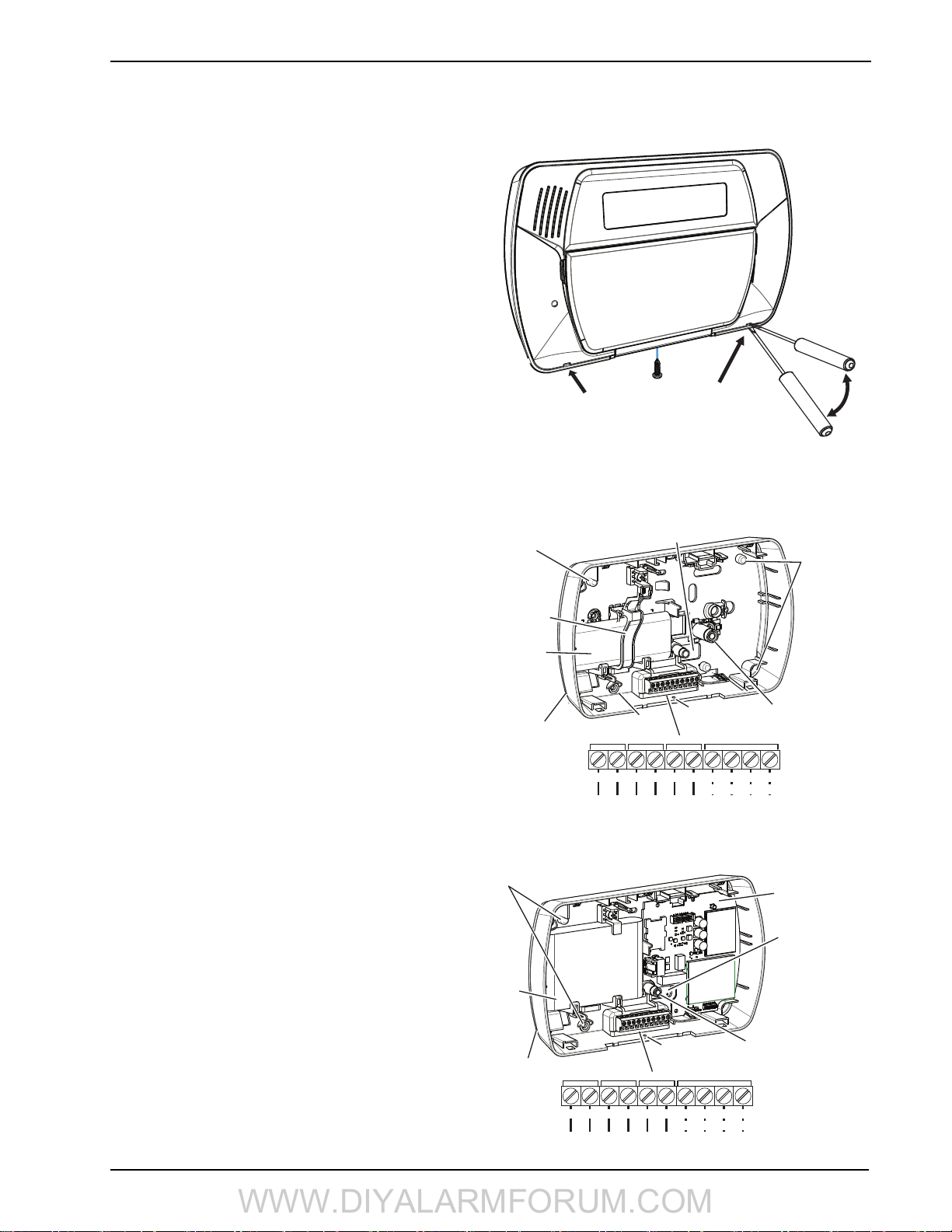
1. If required, separate the front and back covers by removing
the cover screw then inserting a small slotted screwdriver
between the front and back covers and gently twist the
screwdriver to separate.
2. Route Telephone line wiring, I/O Wiring, and AC power
through the cutout in the back cover (see Fig. 2 Mounting &
Wiring details). If Programming with DLS, see “4.2.1 Local
Programming with PC-Link” on page 17. If using Template
programming or Advanced Keypad programming, continue
to the next step.
3. Secure the back cover to the wall with the hardware provided. See figure 2, Mounting & Wiring Details for hole
locations.
NOTE: If mounting unit on a double-ganged box with the
wall tamper feature, secure the back plate to the right
side of the ganged box using the center mounting
holes. This provides the tamper switch with unobstructed access to the wall surface.
4. Connect wiring to the terminals indicated. See Section “2.2
Wiring” on page 6 for details.
NOTE: Do NOT apply power until wiring is completed.
5. Connect battery cable connector to the PC Board.
NOTE: Ensure connector key is oriented correctly.
6. Position the cover onto the back plate. Ensure tamper switch,
if used, is positioned correctly.
7. Insert cover in the top edge of the back plate at a 35° to 55°
angle then snap cover in place.
8. Apply power to the system.
Once the system is wired and mounted, do the following:
• Enroll devices. Enter [*][8][Installer Code][898]. See “2.3
Wireless Device Setup” on page 7.
• If performing Template programming, enter [*][8][Installer
Code][899]. See “4.1 Template Programming” on page 14.
NOTE:
• See DLS Programming on page 17 for reprogramming an
existing Installation.
• AC Power must be present for the alarm system to answer
incoming calls from DLS. After the initial installation 24
Hrs. is required to fully charge the standby battery.
Figure -1, Opening Cover
Remove cover screw
Insert screwdriver in slots indicated.
Gently pry open cover with screwdriver
until cover separates.
Figure -2, Mounting & Wiring Details
SCW9055/57
Mounting Hole
Battery Retainer
Battery
Surface Mount
Wiring Access
AC AC Aux 1 I/O 2+- Ring Tip R-1 T-1
Wiring Access
Mounting Hole
12 V
DC
PGM/ZonesAC Power
Cover screw hole
Telephone Line
Red Grn Gra Brn
2 Installation
Mounting Holes
Wall and Case
Tamper Switch
5
SCW9055/57 Wireless Alarm System
Burglary Zone Wiring Chart
Wire
Gauge
Max wire length to end-of-line resistor
(feet/meters)
22 3000 / 914
20 4900 / 1493
19 6200 / 1889
18 7800 / 2377
Figures are based on maximum wiring resistance of 100
A
I/O
I/O
WWW.DIYALARMFORUM.COM
2.2 Wiring
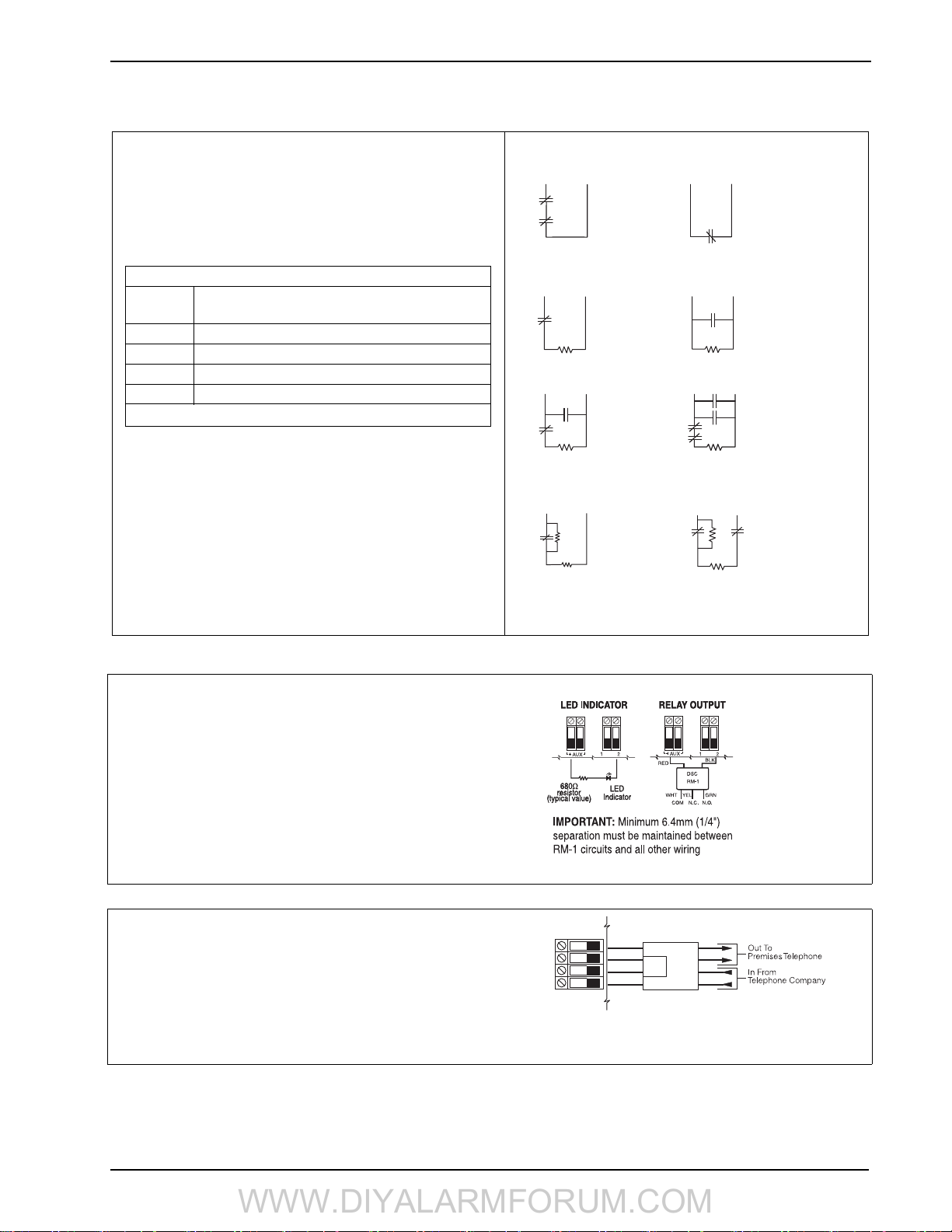
2.2.1. Zone Wiring
Zones can be wired for Normally Open and Normally Closed contacts with Single-end-of-line (SEOL) resistors or Double End-ofLine (DEOL) resistors. Observe the following guidelines:
• For UL/ULC listed installations use SEOL or DEOL only
• Minimum 22 AWG wire, maximum 18 AWG
•Do NOT use shielded wire
• Wire run resistance shall not exceed 100Refer to the chart
below.
Normally Closed Loops - Do NOT use for UL Installations
AUX-
Any I/O
Terminal
Terminal
2 NORMALLY CLOSED
CONTACTS WITH
NO END OF LINE
RESISTOR
Any I/O
Terminal
AUXTerminal
1 NORMALLY CLOSED
CONTACT WITH
NO END OF LINE
RESISTOR
Single End-of-Line (SEOL) Resistor Wiring
Any I/O
Terminal
AUXTerminal
1 NORMALLY
CLOSED
CONTACT WITH
5600Ω
END OF LINE
RESISTOR
Any I/O
Terminal
AUXTerminal
1 NORMALLY OPEN
CONTACT WITH
5600 Ω
END OF LINE RESISTOR
• Section [009] selects hardwired zone definition
• Section [013] Opt [1, 2] selects I/O function as Zone (Input) or
PGM (Output)
• Section [206] Opt [1,2] activates zones 33 & 34
• Sections [133], [134] Opt [14] selects Normally Closed
• Sections [133], [134] Opt [15] selects SEOL resistors
• Sections [133], [134] Opt [16] selects DEOL resistors
CONTACT
Zone Status - Loop Resistance/Loop Status
• Fault - 0 (shorted wire/loop)
• Secure - 5600 (contact closed)
• Ta mp er - infinite (broken wire, open)
• Violated - 11,200 (contact open)
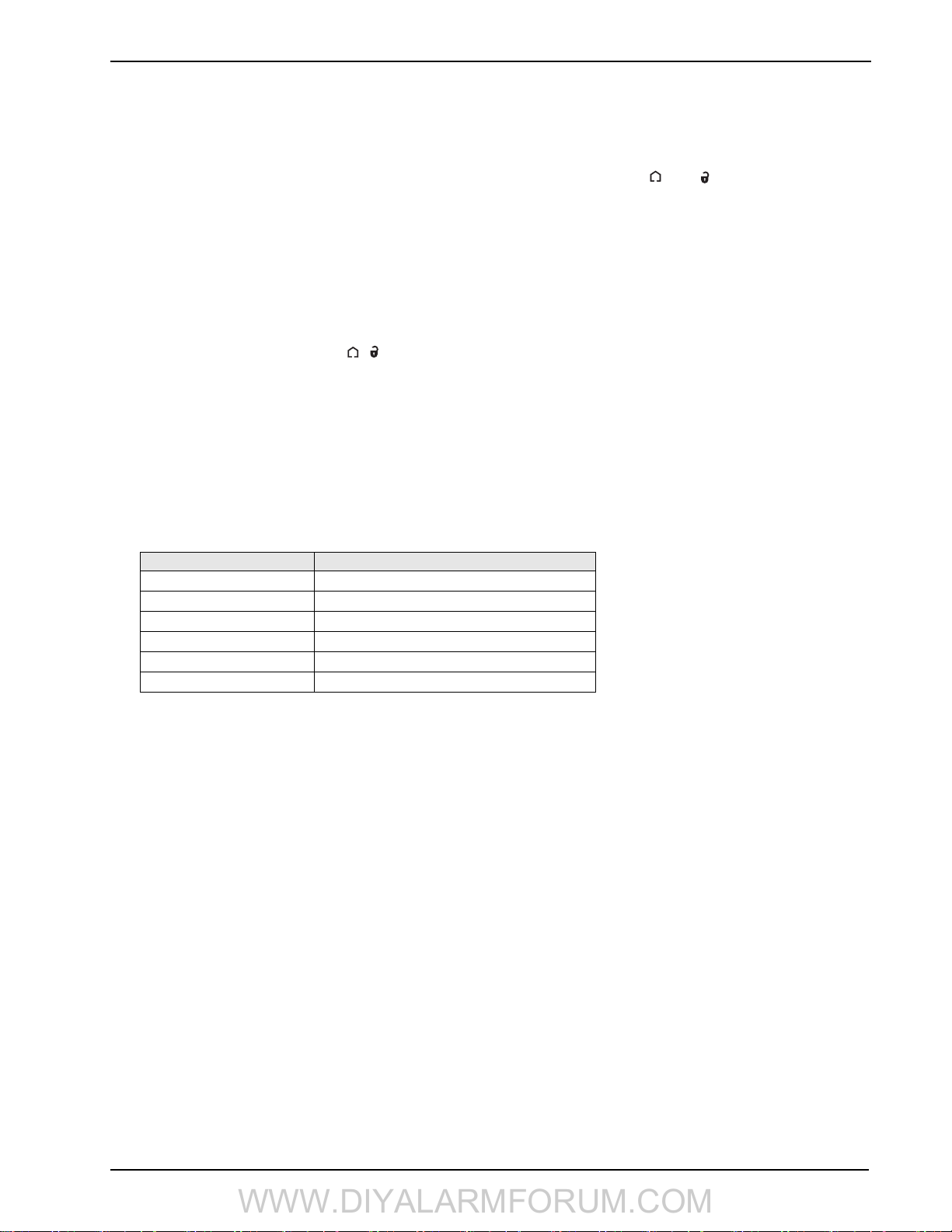
2.2.2 PGM/Aux Power Wiring
PGMs switch to ground when activated by the alarm panel.
Connect the plus side of the device to be activated to the AUX+ terminal.
Connect the minus side of the device to the PGM. Each PGM can provide
50mA output.
NOTE: The alarm panel can provide a maximum of 100mA of AUX current for PGMs, relays, LED’s etc. Min/Max operating voltages for PGMs,
relays and modules is 12V
DC - 12.6VDC.
NOTE: Battery Voltage (6.0-8.4VDC) is boosted internally to supply
12V
DC on the AUX+ output by setting Section [014] Opt. [4] to ON. This
option must be enabled for PGMs used in UL/ULC Residential Burglary
installations. This output can NOT be used for UL/ULC Fire installations.
2.2.3. Telephone Line Wiring
Wire the telephone connection terminals (TIP, Ring, T-1, R-1) to an RJ31X connector as indicated. Use 24 AWG wire minimum for wiring.
For connection of multiple devices to the telephone line, wire in the
sequence indicated.
Communication format is programmed in section [350].
Telephone Call Directions are programmed in section [351]-[376].
Any I/O
AUX-
Terminal
Terminal
1 NORMALLY OPEN
CONTACT AND
1 NORMALLY CLOSED
CONTACT WITH
5600Ω END OF LINE
RESISTOR
Double End-of-Line (DEOL) Resistor Wiring
Any I/O
AUX-
Terminal
RING
R-1
TIP
Terminal
DEOL CIRCUIT
1 NORMALLY
CLOSED CONTACT
WITH 5600Ω
END OF LINE RESISTORS
T-1
BRN
GRA
GRN
RED
LARM
ALARM
CONTACT
RJ-31X
Any I/O
Terminal
Any I/O
Terminal
AUXTerminal
2 NORMALLY OPEN
CONTACTS AND
2 NORMALLY CLOSED
CONTACTS WITH
5600Ω END OF LINE
RESISTOR
AUXTerminal
TAMPER
CONTACT
LED output with
current limiting
resistor and optional
relay driver output
DEOL CIRCUITS
2 NORMALLY
CLOSED CONTACTS
WITH 5600Ω END
OF LINE & TAMPER
RESISTOR
6
Note: For UL listed installations, the installer must verify the communication format with the supervising station at the time of installation.

2 Installation
WWW.DIYALARMFORUM.COM
2.2.4 Battery
For systems without an alternate communicator module, a 1500 mAh NiMh battery pack is included to meet battery standby requirements. For systems with an alternate communicator module, a 3600 mAh Ni-MH battery
pack is included.
Note: UL/ULC Residential Burglary installations require 4 Hr. battery
standby time plus 4 minutes alarm annunciation.
Note: UL/ULC Residential Fire installations require 24 Hr. battery
standby plus 5 minutes alarm annunciation.
Note: Battery life is 3-5 years under typical operating conditions. Battery
capacity deteriorates with age and number of charge/discharge cycles.
Replace battery every 3-5 years.
Note: Do not connect the transformer to a receptacle controlled by a switch. For UL/ULC Installations use a Class 2, power limited, plugin transformer.
2.2.5. AC Wiring
AC Transformer Requirements:
Primary:120VAC, 50/60Hz., 0.33A (NA), 240VAC, 50/
60Hz., 0.165A (EU)
Secondary: 16.5VAC/20VA
The following transformers shall be used:
UL/ULC Listed Installations - PTD1620U-CC
2.3 Wireless Device Setup
This section describes how to configure wireless devices to work with the alarm panel.
2.3.1 Receiver Placement Test
Receiver Placement test ensures the SCW9055/57 is located in an area with low noise and interference and can successfully receive signals from wireless devices.
To perform a receiver placement test:
1. Enter Wireless Device Placement Test mode:
[
✱ ][8][XXXX][904] - for wireless zones
✱ ][8][XXXX][905] - for wireless keypad/ IT-410
[
✱ ][8][XXXX][906] - for wireless sirens
[
[ ✱ ][8][XXXX][907] - for wireless repeaters
2. The Yellow LED on the SCW9055/57 lights indicating unacceptable RF traffic level or noise floor level. Once Wireless Device
Placement Test mode is entered, Receiver Placement Test is continuously active until placement mode is exited or Installer programming times out.
2.3.2 Wireless Device Enrollment
Enrollment consists of programming the device's Electronic Serial Number (ESN) into the panel so that it can be identified when an
event is communicated. Two-way devices must also initiate communication with the control panel to complete the enrollment process.
The control panel assigns a unique system ID, device ID and encryption key to the device. This information is stored in the device’s
memory.
Note: The ESN is a 6-digit alphanumeric number located on a removable sticker on the wireless device.
Methods of Enrollment
Two methods of enrollment are available:
• Quick Enroll – Used to enroll new devices on the system (see below for procedure). The Quick Enroll procedure performs one-way
and two-way enrolment communications in the background. The enrollment procedures for both types of devices are identical.
• Manual or DLS Enroll – See Installer Programming or DLS Programming (Section [804]). Manual or DLS enrollment of wireless keys requires the device to be physically triggered to complete the enrollment.
Enroll wireless devices in the following sequence: Keypad, Sirens, Sensors, Pendants, Wireless Keys, Repeaters.
Refer to the associated installation sheets for additional details on how to activate specific wireless devices.
Enrolling The Secondary Keypad
During initial power up of the alarm panel, a 2-minute window is established for enrolling the secondary keypad. If the AC Power and
Ready LEDs flash for the duration of this window, the keypad must be powered up and enrolled within this period. If not (i.e., The AC
Power and Ready LEDs stop flashing), power down the panel then power up again to re-open the 2-minute enrollment window.
To enroll a keypad:
1. Power up alarm system.
• Connect alarm system to AC Power. The Ready and AC LEDs flash for 2 minutes.
2. Power up keypad.
• Connect keypad to AC power or install new batteries. After a few seconds the keypad may beep rapidly and the LCD displays
the following: “Hold [1] and [
•Press the [✱ ] and [1] keys simultaneously to enroll the keypad. “WFKP Enrollment Successful” is displayed.
If the “Failed to Enroll” message is displayed perform the following:
i
• Retry the enrollment.
• Reposition the keypad closer to the control panel.
• Verify that the READY and POWER LED indicators are flashing on the panel. If not, disconnect the panel from AC and DC
power sources then reconnect.
• Check for RF interference. See “2.3.2 Wireless Device Enrollment” on page 7 for more information.
✱ ] to Enroll Keypad.”
7
SCW9055/57 Wireless Alarm System
WWW.DIYALARMFORUM.COM
Quick Enrolling Keypads, Sirens, Wireless Keys & Repeaters
1. Enter [
✱ ][8][5555][898]. The following is displayed: “Wireless Enrollment Mode.”
2. Activate the device as indicated below or in the device’s installation sheet.
• Additional keypad: Press the [
✱ ] and [1] keys simultaneously.
• Siren: Power up the device, press the Tamper button or the test button to enroll.
• Wireless key: Press any key to activate. To re-enroll on another system, press and hold and simultaneously for 3 sec-
onds.
• For IT-410 - Press Enrollment button (Note: A keypad must be enrolled before the IT-410 can be enrolled).
• Ensure that dip switch 3 on the repeater is in the off position before quick enrolling a repeater on the SCW9055/57. Press the
tamper button to enroll.
3. The Electronic Serial Number (ESN) is displayed on the keypad. Press [
✱ ] to confirm the ESN. If the ESN is incorrect press [#]
then repeat this step.
4. After successful confirmation of the ESN, the system prompts for the slot number.
• The next available slot for the device type is displayed. Press [
✱ ] to accept or enter the slot number.
(keypads = 01, Sirens = 01-02, wireless keys = 01-16, wireless repeaters = 01-04).
• To re-enroll a wireless key press simultaneously for approximately 3 seconds.
Quick Enrolling Sensors & Pendants
1. Enter [
✱ ][8][898]. The LCD displays the following: “Wireless Enrollment Mode.”
2. Place the wireless device in the desired location.
3. Activate the device as described in the associated installation sheet. The electronic serial number (ESN) is displayed.
4. Press [
✱] to confirm the serial number. If the serial number is incorrect, press [#] and repeat this step. After successful confirmation
of the serial number, the system prompts for the zone number. The next available zone is displayed.
5. Enter a zone number (01-32) then press [
✱ ] to accept. The next available zone is preloaded.
NOTE: Only one device may be enrolled in each zone. If a zone already has a device enrolled, press [*] to overwrite the zone or
[#] to enter another zone number.
6. After successful entry of the zone number, the system prompts for the zone type. (The recommended zone type is displayed). Press
✱ ] to accept the zone type or enter:
[
Device Type Zone Definition
2 Door/Window Contact [01] Delay 1
3 PIR or Glassbreak [05] Interior, Stay-Away
4 Smoke Detector [88] Standard 24-Hour Fire (Wireless)
5 Pendant [16] 24-Hour Panic
6 & 9 Wireless Key N/A
A Wireless Repeater N/A
7. After successful entry of a valid zone type, the alarm panel automatically enters individual placement test mode for the zone that
was enrolled. “Activate Device for Test, Exit # ” is displayed on the screen. The device may now be placement tested. See below
for details.
8. Press the [#] key to return to the quick enroll screen. Repeat the above procedure for the next zone.
Quick Enrolling Proximity Tags
If this function is available on the keypad, the [
✱ ][5] menu provides the option to assign a proximity tag to an access code once the
access code has been entered. Swipe the tag to enroll it during user access code assignment.
To unenroll a proximity tag, the user code must be deleted.
i
Manual Enrollment
To manually enroll a 2-way wireless device:
1. Enter [*][8][5555][804].
2. Select the programming section corresponding to the device type:
• Wireless sensors and pendants
• Wireless Key
• Wireless Keypad
• IT-410
• Wireless Siren
• Wireless Repeater
[804][001]-[032]
[804][101]-[116]
[804][201]
[804][202]
[804][301]-[302]
[804][401]-[404]
3. Enter the device serial number.
4. Activate the device as indicated in the device’s installation sheet. This can be done while in Installer Programming or after exiting.
The device is now enrolled.
8

2 Installation
WWW.DIYALARMFORUM.COM
2.3.3 Wireless Device Placement Test
Perform wireless device placement testing on keypads, sirens, sensors and repeaters only.
• During placement test, the sensitivity of the wireless receiver is reduced significantly. This is done to ensure that, if consistent
good placement test results are generated with reduced sensitivity, the product should have more than adequate range when placement test exits and the sensitivity level returns to normal. During placement test, try to avoid tripping multiple devices at the same
time as this may cause collisions. A collision may cause a bad placement test result, despite having adequate coverage between the
receiver and the transmitter.
• During placement test, the wireless receiver will require 3 out of 4 wireless packets to be received before a good placement test
result is obtained. Outside of the placement test mode, one wireless packet received is enough to generate an alarm or trouble condition.
• This test is NOT required for wireless keys or panic pendants. Verify that wireless keys operate within the desired operating area
by arming/disarming the system.
• Test each wireless device a minimum of 5 times to ensure the location is good. Ideally all 5 attempts should provide a good placement test result.
• If a device tests bad, reposition it and test again. A slight change in placement, or the orientation of the transmitter, can cause significant differences in the signal strength and range of a wireless device.
• Avoid mounting wireless transmitters on metal door or window frames whenever possible.
Note: The indoor siren sounds during placement test, even if it is disabled in section [804][311]-[314] option 1. The outdoor siren
sounds during placement test only if section [804][311]-[314] option 1 is enabled.
Wireless Zone Placement Test
1. To placement test a zone, press [
“Select Device for Test < >.”
2. To perform a placement test on an individual zone, type the 2-digit zone number (01 to 32).
To perform a global placement test on a zone, type [00]. In this mode, all wireless zones, keypads, sirens and repeaters are placement tested at the same time. To perform another Wireless Zone Placement test, exit the global placement test by pressing [#] and
begin a new test.
3. Place the wireless device(s) in the intended mounting location(s).
4. Activate the device(s) as described in the associated installation sheet. The device name and zone number are displayed on the
LCD.
• If the alarm system receives a STRONG signal, the bell sounds once and “Location is Good” is displayed on the LCD.
• If the alarm system receives a WEAK signal, the bell sounds 3 times and “Location is Bad” is displayed on the LCD.
• If the alarm system indicates no response, reposition the wireless device(s) and repeat the test.
• For individual placement tests, repeat step 2-3 for each device.
5. When placement testing is complete, press [#] to exit Installer Programming.
Two-way wireless keys must be activated by pressing any key before they become functional.
To placement test a wireless keypad, press number keys 0-9.
i
To placement test a wireless siren or repeater, press the Test button or tamper the device.
✱ ][8][XXXX][904]. [XXXX] represents the installer code. The LCD displays the following:
2.3.4 Individual Wireless Device Placement Test
Individual placement testing can be performed on wireless devices. Use the scroll keys or enter a 2-digit entry to select a specific
device.
1. To individually test wireless devices, press:
✱ ][8][XXXX][905] - for wireless keypads/IT-410
[
✱ ][8][XXXX][906] - for wireless sirens
[
✱ ][8][XXXX][907] - for wireless repeaters
[
NOTE: [XXXX] represents the installer code (default 5555).
2. Select the wireless device you want to placement test by typing the number of the device. In section [905], type 01 for WT5500
keypad or 02 for IT-410. In section [906], type 01-02 for siren 1 or 2. In section [907] type 01-04 for wireless repeater 1-4. Alternatively, scroll to the desired device and press [
3. Place the wireless device in the intended mounting location.
4. Activate the device as described in the associated installation sheet.
• If the alarm system receives a STRONG signal the bell sounds once and “Location is Good” is displayed on the LCD.
• If the alarm system receives a WEAK signal the bell sounds 3 times and “Location is Bad” is displayed on the LCD.
• If the alarm system indicates no response, reposition the wireless device and repeat the test.
5. Repeat Step 2-3 for each device. Once the placement test is complete for the device, press [#] once to select the next similar device.
6. When placement testing is complete, press [#][#][#] to exit Installer Programming.
✱ ] to begin the individual placement test.
2.4 Alternate Communicator Module Setup/Initialization
After system installation and programming, ensure that the following sections are programmed:
• Central Station Phone Number, (Template Programming - Entry 5) (if applicable, in sections [301]-[303] & [305])
• Account code, section [310], (Template Programming - Entry 6)
• Communications Format, Section [350]- set to [03] Contact ID or [04] SIA FSK
• alternate communicator Module Enable section [382] Option [5] - set to “alternate communicator module enabled”
9

SCW9055/57 Wireless Alarm System
WWW.DIYALARMFORUM.COM
3 Operation
3.1 Operating Modes
3.1.1 – Away Arming
Away Arming arms the entire system including the perimeter and interior devices. The Ready light must be on to arm the system. If the Ready
light is off, ensure all protected doors and windows are secure or bypassed. To arm in Away mode, press and hold the Away function key for 2
seconds or enter a valid user code and leave the premises through a door programmed as Delay. The Armed light turns on when a function key
is pressed or an access code is entered. If the Audible Exit Delay option is enabled, the keypad beeps once every second during the exit delay
(and three times a second during the last 10 seconds) to alert the user to leave. The Ready light turns off when the Exit Delay ends.
NOTE: In Away Arming mode, manually bypassed zones are logged and communicated to the central station.
3.1.2 – Stay Arming
NOTE: Zones must be programmed with zone definitions (05 Interior Stay/Away, 06 Delay Stay/Away, or 32 Instant Stay/Away) for
this function to work.
Stay Arming is intended to arm the perimeter of the premises while permitting movement within. The Ready light must be on to arm the
system. If the Ready light is off, ensure all protected doors and windows are secure or bypassed. To Stay arm the system, press and hold
the Stay function key for 2 seconds or enter a valid user code and stay within the premises (do NOT violate a door programmed as
Delay). The Armed light turns on once a function key is pressed or an access code is entered. If the Stay function button is used, the
keypad will not beep during the exit delay and the user can still exit the building without the system reverting to Away mode. When a
user code is used, the keypad beeps if the Audible Exit Delay option is enabled. The Ready light turns off when the exit delay ends.
NOTE: In Stay Arming mode, all auto-bypassed stay/away and night zones are logged and communicated to the central station.
3.1.3 – Night Arming
Night arming is intended to arm the perimeter and restrict movement to designated areas in the interior (e.g., hallways from bedrooms to bathrooms). If night zones are programmed, entering [
grammed as night zones. The panel can also be armed in Night mode by pressing the Night Arm function key for 2 seconds while the system is
disarmed. The Ready light must be on (disarmed) or the system must be armed in Stay mode to Night arm the system. In Night mode only night
zones (Zone definition 37) are bypassed. When activated, no acknowledgement beeps are sounded, the exit delay is silent and the panel logs
“Armed in Night Mode.” If no night zone types are programmed, the system arms in Away mode and the panel logs “Armed in Away Mode.”
NOTE: In Stay Arming mode, all auto-bypassed night zones are logged and communicated to the central station.
3.1.4 – Disarming
The user must enter through a door programmed as Delay. Upon entering, the keypad emits a steady entry delay tone (and a pulsing
tone during the last 10 seconds of entry delay) to alert the user to disarm the system. To disarm the system, enter a valid user code, present a proximity tag or use a wireless key. If an alarm occurred while the panel was armed, the keypad displays “Alarm in Memory” and
the zone(s) that went into alarm during the armed period. Press the [#] key to return the keypad to the Ready state.
3.2 Language Selection
The keypad can be programmed to display messages and labels in different languages. Languages can be selected before the keypad is
enrolled on the system. Perform the following when in “Ready to Arm” mode or at the Installer Programming menu:
(1) Press and hold both scroll keys [< >] simultaneously until language options are displayed.
(2) Scroll to the desired language using the scroll keys [< >].
(3) Press [
✱ ] to select the desired language.
3.3 [ ✱ ] Commands
The following is a list of the [ ✱ ] commands available and a description of each:
[ ✱ ][1] Bypass (disarmed state)/Reactivate Stay/Away Zones (armed state)
✱ ][2] Display Trouble Conditions
[
✱ ][3] Display Alarm Memory
[
✱ ][4] Door Chime Enable/Disable
[
[
✱ ][5][Master/Supervisory Code] User Code Programming and Proximity Tag Enrollment
✱ ][6][Master/Supervisory Code] User Functions
[
✱ ][7][1/2] Command Outputs 1 and 2
[
[
✱ ][8][Installer Code] Installer Programming
✱ ][9][User Code] No-Entry Arming
[
✱ ][0] Quick Arm (disarmed state)/Quick Exit (armed state)
[
[ ✱ ][1] – Bypass/Re-activate Stay/Away and Night Zones
✱ ][1] to enter the bypass mode. If the Code Required for Bypass option is enabled, enter a valid user code. The keypad will dis-
Press [
play ‘Scroll to Bypass Zones.’ The keypad will display the programmed zone labels for the zones and include the letter ‘O’ in the bottom, right corner if the zone is violated or the letter ‘B’ if the zone is bypassed. Scroll to the appropriate zone and press the [
change the bypass status (or enter the 2-digit zone number). Once the correct zones are bypassed, press [#] to exit.
✱
][1] while the system is armed in stay mode will activate all interior zones except those pro-
✱ ] key to
10

3 Operation
WWW.DIYALARMFORUM.COM
Additional Bypass Commands:
Bypass Recall: Press [99]. The keypad will recall the last group of zones that were bypassed.
Clear Bypass: Press [00]. The keypad will clear the bypass on all zones.
Save Bypass: Press [95]. The keypad will save which zones are manually bypassed.
Recall Save: Press [91]. The keypad will recall the bypassed zones that were saved.
Re-activate Stay/Away and Night Zones:
Press [ ✱ ][1] when the system is armed in the Stay mode to change the armed status to Away mode or Night mode. The system will add
the Stay/Away zones back into the system after the exit delay time expires.
If any zones are programmed as Night Zones (zone definition 37) pressing [
✱ ][1] will activate the Night mode instead of Away mode.
Only Night Zones will be bypassed.
[ ✱ ][2] – Trouble Display
Refer to Section 6: Testing & Troubleshooting, for troubleshooting assistance and a detailed description of all trouble conditions.
✱ ][3] – Alarm Memory Display
[
Pressing the scroll < > keys will display an “Alarms in Memory” message if an alarm occurred during the last armed period. Pressing
[
✱][3] will display the message “Scroll to view Alarms.” Scrolling will display the zones that went into alarm. To clear the memory, arm
then disarm the system.
[ ✱ ][4] – Door Chime Enable/Disable
Press [
✱][4]. The keypad emits 3 rapid beeps to indicate that the door chime feature is enabled or a steady 2-second tone to indicate it is
disabled. The same function can be performed by pressing and holding the Chime function key for 2 seconds.
[ ✱ ][5] – Program User Codes
The following table identifies available user codes:
Code Type Function
[01] – [16]
[40]
General User Codes
Master Code
Determined by attributes programmed below
All attributes described below
Programming User Codes
Press [ ✱ ][5] followed by the master code. The keypad displays the first user (user 01) and includes the letter “P” if the user code is programmed. Scroll to the appropriate user number and press the [
✱ ] key to program the user (or enter the 2-digit user number). Enter a
new 4 or 6-digit user code or press [✱ ] to delete the user code. After the user code is programmed or deleted, scroll to another user num-
ber or press [#] to exit.
NOTE: Proximity tags can be assigned to a programmed user code on WT5500P keypads. After assigning a user code, swipe the tag to
assign it to the user. A T is displayed in the lower right hand corner of the user code indicating that a tag is associated with it.
To delete a proximity tag, the user code must be deleted. Refer to the Proximity Tag Installation Sheet for details. The proxim-
ity tag can be used in place of the access code for any of the featured referred to in the Operation section of this manual.
Programming User Attributes
✱ ][5] followed by the master code or supervisor code. Press [9] followed by the 2-digit user number to view user attributes.
Press [
To change user attributes, press the number corresponding to the attribute or scroll to the desired attribute and press [
✱ ]. When the cor-
rect attributes are assigned to the user, press [#] to exit. To change the attributes for another user, press [9] followed by the 2-digit user
number. When finished, press [#] to exit.
NOTE:
• These attributes affect the operation of wireless keys.
• Wireless key numbers (01-16) correspond with user access codes (01-16).
• Duress codes are not valid when entering [
✱ ][5], [ ✱ ][6] or [ ✱ ][8] sections.
• Duplicate codes and codes that are ± 1 of an existing code can not be programmed.
[1] Supervisor’s Code: This code is used for validation when entering the [
✱ ][5] User Code Programming section and [ ✱ ][6]
User Functions section. Note, the supervisor’s code can only validate programming for codes with equal or lesser attributes.
The supervisor’s code also allows the user to create bypass groups if an access code is required to enter [
✱ ][1] Bypassing.
[2] Duress Code: Duress codes are standard user codes that transmit the Duress Alarm Reporting Code whenever the code is
entered to perform any function on the system.
[3] Bypass Zones: The user can manually bypass zones if bypassing requires an access code.
[4] Phone Access: This attribute is used to specify which users can access the system remotely.
Note: After 5 invalid access codes, remote access is locked out. The invalid access codes timer is cleared every 60 minutes.
Valid access codes do not reset the invalid access code count.
[5-6] Future Use
[7] Bell Squawk On Arming/Disarming: The panel squawks the bell when the user arms using the Away function key and a
user code, or if the away function key is pressed on an identified wireless key.
11

SCW9055/57 Wireless Alarm System
WWW.DIYALARMFORUM.COM
[8] One-time Use Code: The one-time-use code allows unlimited arming but only permits a single disarming once a day. The
Disarm function is restored at midnight.
[ ✱ ][6] – User Functions
To access the User Functions section, press [
✱ ][6] followed by the master or supervisor code. Select one of the functions described
below by pressing the corresponding number or scrolling to the desired option then pressing [ ✱ ].
[1] Program Time and Date: Enter the time and date using the following format [HH:MM] [MM/DD/YY]. Program the time
using military standard (e.g., 8:00 pm = 20:00 hours).
[2]-[3] Future Use
[4] System Test: The system activates the siren output on medium volume for 2 seconds followed by full volume alarm for 2
seconds. All display lights and LCD pixels turn on.
[5] System Serv/DLS: Installer Programming, either by DLS or via the keypad ([
✱ ][8]), is enabled for 6 hours.
[6] User Initiated DLS: The panel attempts to call the DLS computer.
[7] Future Use
[8] User Walk Test Mode: This mode tests the operation of each detector in the system. Press [
✱ ][6][Master Code][8] to initiate
Walk Test. While in Walk Test, the Ready, Armed, and Trouble LED's on the keypad flash to indicate that the test is active.
When a zone is violated during the test, a 2-second tone sounds on all system keypads to indicate that the zone is working
correctly. Re-entering [
✱][6][Master Code][8] exits Walk Test. The system automatically ends the test after 15 minutes without
zone activity. An audible warning (5 beeps every 10 seconds) is sounded, beginning 5 minutes before the test ends.
NOTE: Do not activate [F]ire, [A]uxiliary and [P]anic keys, or Fire and CO zones during a walk test. If an [F], [A], or [P] key is
pressed during a walk test, or if a fire or CO alarm is detected, walk test ends automatically and the reporting codes for the
alarm are sent immediately to the monitoring station.
[9] Late to Open Control: Notifies a user if their alarm system is not disarmed by a programmed time of day (see Late to Open
Time of Day). If the system is not disarmed at the programmed time, an alert is sent to the monitoring station. The keypad
displays “Late to Open is Enabled” and sounds a beep if [9] is pressed within the User Functions menu when this feature is
off. The LCD keypad displays “Late to Open is Disabled” and sounds an error tone if [9] is pressed within the User
Functions menu when this feature is on.
[0] Late to Open Time of Day: Sets the time for Late to Open Control programmed for attribute [9] operation. Valid entries are
00:00 - 23:59. Entering 99:99 disables the late to open feature for that day. After [0] is pressed in the [
✱][6] menu, acknowledge
beeps are sounded and the message “Press (✱) for < > Sunday” is displayed on the keypad. Pressing [>] scrolls through each day
of the week from Sunday to Saturday. While in the Late to Open menu, entering keys 1-7 also selects the day.
Additional Keypad Functions
The following additional keypad functions are available:
Event Buffer: View the 500-event panel buffer
Brightness Control: Adjust the display backlighting level for optimal viewing
Contrast Control: Adjust the display contrast level for optimal viewing
Buzzer Control: Adjust the keypad buzzer tone for optimal sound
SMS Phone Number Programming: Program up to 8 phone numbers for the panel to accept incoming SMS commands
✱ ][7][1 or 2] – Command Outputs (1&2)
[
Press [ ✱ ][7] then [1] or [2]. If the Command Output Code Required option is enabled, enter a valid user code. The panel activates a
command output assigned to any PGM.
[ ✱ ][8] – Installer Programming
✱ ][8][Installer Code] to enter Installer Programming. Installer programming allows the installer to program all system func-
Press [
tions.
Refer to section 5: Installer Programming, for details.
[ ✱ ][9][User Code] – No-Entry Arming
Press
[✱][9]
followed by a valid user code. The system arms in the Stay mode after the exit delay expires and removes the entry delay. All
zones programmed as Delay function in the same way as Instant zones. The system flashes the Armed light to indicate that it is armed
with no entry delay.
[ ✱ ][0] – Quick Arm/Quick Exit
Quick Arm: When disarmed, press [
Quick Exit: When armed, press [
✱ ][0] to arm the system. Quick Arm is equivalent to entering your user code.
✱ ][0] to activate Quick Exit. Quick Exit allows you to exit the premises without disarming the sys-
tem.The system allows a single zone programmed as Delay to be violated and restored once during the following 2 minute time period
without changing the status of the system.
12

3 Operation
WWW.DIYALARMFORUM.COM
3.4 Function Keys
The keypad has 5 programmable one-touch function keys located in a column down the right-side of the keypad. These keys can also be
activated by pressing and holding number [1] through [5] respectively for 2 seconds. The default for these keys are as follows:
[1] Stay Arm [4] Bypass
[2] Away Arm [5] Quick Exit
[3] Chime Enable/Disable
3.5 System Removal Prevention
The SCW9055/57 includes a feature to prevent intruders from disabling the system by removing it from the wall.
This feature operates as follows:
1. When an entry delay is started, the panel notifies the alternate communicator.
2. The communicator establishes contact with the network as soon as it receives the above notification.
3. If a system tamper is detected, the panel notifies the communicator, sending a burglary event to the central station.
13

SCW9055/57 Wireless Alarm System
WWW.DIYALARMFORUM.COM
4 Programming
The SCW9055/57 can be programmed using the following methods:
Programming Method Description Procedure
Template Programming Allows the minimum required data to be pro-
grammed. It also allows for the setup of DLS
downloading software.
DLS Programming Allows programming to be downloaded using
DLS-IV™ software.
• DLS programming can be performed
with a PC-Link cable and a PC with DLS-IV
software installed.
• DLS programming can be performed remotely
via telephone line, Cellular network or the
Internet.
Installer Programming Allows direct access to all programming sections.
Template programming is accessed from here.
locally
4.1 Template Programming
Template Programming allows the installer to quickly program the minimum functions required for basic operation. The installer is
prompted to enter a 4-digit code that selects predefined zone definitions, reporting code formats, and troubles/restores (see the tables for
digits 1 - 4 below).
Perform the following after completing the hardware installation. Ensure you have the information listed below available for program-
ming. Record this information in “5.3 Programming Worksheets” on page 20 for future reference:
• Monitoring Station Telephone Number - Provided by your alarm monitoring service.
• Monitoring Station Account Code - Provided by your alarm monitoring service.
• Downloading Access Code.
• Entry Delay - Installer defined.
• Exit Delay - Installer defined.
• Installer Code - Programmable, unique 4-digit code. The default value is [5555].
To perform template programming:
1. At the “Ready to Arm” screen, enter [*][8][5555][899].
2. At the “Enter Data” screen, enter [0001] to accept the existing default programming. See the tables
below for details of digits 1-4.
NOTE: Once this section has been entered, the Installer cannot exit until all sections are completed.
Enter new data and/or press # key to accept the displayed data and proceed to the next section.
Changing a single digit, then pressing the # key advances to the next section but does not save
the changed data. Enter all 4 digits or scroll to the end of template programming and exit to
save data.
3. After entering [0001], the first telephone entry is displayed. Enter the monitoring station telephone
number after the “D.” Press [#] to complete the entry.
4. After programming the first telephone number, enter a system account code.
• The system account code can be any 6-digit combination of numbers (0-9) and letters (A-F). If the
system account code is 4-digits, the last two digits must be “FF.”
• To enter letters A through F, press [*] then the numbers 1 through 6 for the letter A through F
respectively. Press [*] again to revert back to decimal entry. E.g., to enter “1234FF” press
[1234*66].
See section [310] for additional details.
5. After programming the system account code, the downloading access code is displayed. Enter the new
downloading access code or press [#] to proceed to the next step. See section [403] for additional
details.
6. The entry delay is the amount of time given to disarm the alarm system, after entering the premises
through a delay type zone, before an alarm is sounded. Press [>][>][>] to accept the default time of 30
seconds (030) or enter an entry delay between 001 and 255. E.g., Press 020 for a delay of 20 seconds.
See section [005] for additional details.
7. The exit delay is the amount of time given to exit the premises after pressing the Arm key before the
alarm system is armed. Press [>][>][>] to accept the default time of 120 seconds or enter an entry
delay between 001 and 255. E.g., press 030 for a delay of 30 seconds. See section [005] for additional
details.
Press [899] at the “Enter Section” screen.
See Template Programming below for details.
DLS Programming can be set up from Template Programming (See Steps 3, 4 and 5) or from Installer Programming (See programming sections [401]-[404]).
Press [*][8][Installer Code] while the system is disarmed.
Refer to Installer Programming in section 4.3 for
details.
14
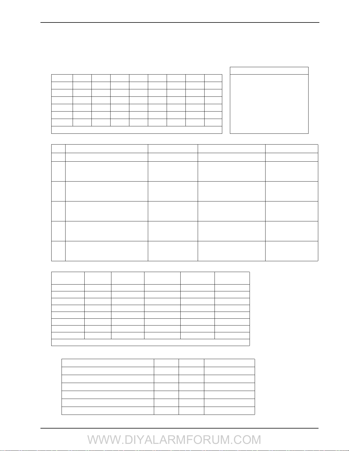
4 Programming
WWW.DIYALARMFORUM.COM
8. After programming the exit delay, enter a 4 or 6-digit installer code depending on the value in section
[701] option 5. See “[006] Installer Code” on page 20 for installer code details.
9. Press [#] to exit Template Programming.
• Digit 1 selects 1 of the following 6 options for Zone definitions for the first 8 zones. A “0” in the digit 1 location indicates that the
default settings for the first 8 zones are in place unless overridden. See Section [001]-[002] on page 20 for defaults.
Zone Definitions (Options 1- 6)
OptionZn1Zn2Zn3Zn4Zn5Zn6Zn7Zn8 1 Delay 1
1 13334444 2 Delay 2
2 133555588 3 Instant
3 133555587 4 Interior
4 11333333 5 Interior Stay/Away
5 13365555 6 Delayed Stay/Away
6 133655588 87 Delayed 24Hr. Fire (Wireless)
Refer to “[001]-[002] Zone Definitions” on page 40 for details 88 Standard 24 Hr. Fire (Wireless)
• Digit 2 selects 1 of the following 6 options for Reporting Codes
Opt# Phone Line 1 Programming Section Phone Line 2 Programming Section
1 Disabled [380] Opt 1 OFF Disabled
2 SIA automatic reporting codes enabled [350] 1st Phone # [04]
[380] Opt 1 ON
[381] Opt 3 OFF
3 Contact ID reporting codes enabled [350] 1st Phone # [03]
[380] Opt 1 ON
[381] Opt 7 OFF
4 SIA automatic reporting codes enabled [350] 1st Phone #[04]
[380] Opt 1 ON
[381] Opt 3 OFF
5 Contact ID reporting codes enabled [350] 1st Phone # [03]
[380] Opt 1 ON
[381] Opt 7 OFF
6 Contact ID reporting codes enabled [350] 1st Phone # [03]
[380] Opt 1 ON
[381] Opt 7 OFF
SIA automatic reporting codes
enabled
SIA automatic reporting codes
enabled
Residential dial
enabled
Residential dial
enabled
Contact ID reporting codes
enabled
[350] 2nd Phone # [04]
[350] 2nd Phone # [04]
[381] Opt 3 OFF
[350] 2nd Phone # [06]
[350] 2nd Phone # [06]
[350] 2nd Phone # [03]
• Digit 3 selects 1 of the 8 following options
Option
1
2
3
4
5
6
7
8
indicates included, Blank indicates default setting, indicates disabled
• Common Group - Sets all Reporting Codes to Automatic
Description Phone 1 Phone 2 Sections
Set all reporting codes to automatic [320] - [348] FF
Alarm/restore call directions enabled [351]
Tamper/restore call directions disabled [359][1] OFF, [2] OFF
Opening/closing call directions disabled [367][1] OFF, [2] OFF
Maintenance call directions enabled [375][1] ON, [2] OFF
Test transmission call directions disabled [376][1] OFF, [2] OFF
Common
Group
Selected
Tro ub le s
Openings/
Closings
Zone
Restores
DLS/Installer
Lead In/Out
[1] ON, [2] OFF
15
SCW9055/57 Wireless Alarm System
WWW.DIYALARMFORUM.COM
• Selected Troubles - Enables the following Troubles
Trouble [345] Alarms [346] Restore
Battery FF FF
AC Failure 00 00
Fire Trouble FF FF
Aux PS FF FF
TLM XX 00
General System 00 00
FF = General System Trouble, 00 = Disabled, XX = Not transmitted
• Openings & Closings - Sets Residential Dial Reporting Codes for all openings and closings
Users CLOSINGS, Residential Dial Reporting Codes Section
1-85152535455565758[339]
9-16 61 62 63 64 65 66 67 68 [339]
40 99 FF FF FF FF XX XX XX [341]
Users OPENINGS, Residential Dial Reporting Codes Section
1-81112131415161718[342]
9-16 21 22 23 24 25 26 27 28 [342]
40 98 FF XX XX XX XX XX XX [344]
Enable Opening/Closings call directions for phone 2
FF=Communicates in automatic mode, XX=Not used
[367] Opt 2 ON
• Installer Lead-in/Lead-out and DLS Lead-in/Lead-out
DLS Lead In
Sect [347] Opt 4
Disabled for all template options except option 8
Digit 4 indicates/selects one of the three following DLS connections
Double Call
Option
1 000
2 008
3 008
4 008
Sect [401] Opt 1
DLS Lead Out
Sect [347] Opt 5
Call Back
Sect [401] Opt 3
Installer Lead Out
Sect [347] Opt 11
User Call Up
Sec [401] Opt 4
Installer Lead In
Sect [347] Opt 12
#Rings
Sect [406] Opt 3
16
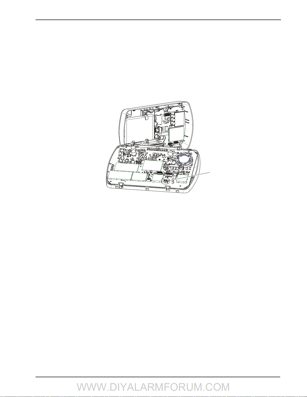
4 Programming
WWW.DIYALARMFORUM.COM
4.2 DLS Programming
4.2.1 Local Programming with PC-Link
Follow the steps below in the sequence indicated to set up local programming using DLS:
1. Connect AC Wiring before mounting the back plate.
NOTE: In a new installation, the backup battery requires 24 Hrs. charging. AC Power is required for
PC-Link Programming until battery is charged.
2. Remove the front cover from the backplate, taking care not to disconnect the alternate communicator module and battery connectors.
3. Initiate a DLS PC-Link session on the DLS computer.
4. Plug in PC-Link header.
5. Initiate DLS session on the DLS computer.
Figure -1, PC-Link Connection
PC-Link
Connector
NOTE: Connecting the DLS PC to the system automatically initiates the connection.
6. When the session is complete, remove the PC-Link cable from the alarm system.
7. Complete the installation.
4.2.2 Local Firmware Upgrade
1. If the unit is mounted on the wall, remove the front cover from the back plate or remove the entire unit from the wall. Plug in the
DLS header. Power down and power up the unit.
NOTE: The DLS session must be initiated within 10 seconds of power up. Do not attempt to perform
a firmware upgrade if low battery trouble is present.
2. Open the Flash Utility application within DLS, select the latest firmware file from the Web or browse to the saved flash file on
your hard drive. Follow the steps as prompted by the Flash Utility application. A message is displayed when download is complete.
3. Once the firmware update is complete, the panel powers up.
4.2.3 Remote Firmware Upgrade
The panel firmware can be upgraded remotely via communicator. If a firmware upgrade is available or if the installed firmware is
faulty, the latest version is installed. During the update, "FW Updating" is displayed on the on-board LCD. If the firmware update fails,
"System Error" (top line) "Service Req." (bottom line) is displayed.
The Panel performs a firmware update under the following conditions:
• The Panel is not armed
• No AC trouble is present
• No low battery trouble is present
• No FTC trouble is present
• Every alarm in memory has been viewed
• No events are being communicated
4.2.4 Remote Programming (via telephone line)
Refer to Section “[401] First Downloading Options” on page 30 and page 55 for details.
NOTE: AC Power must be present for the alarm system to answer incoming calls from DLS.
4.3 Installer Programming
Enter [*][8][Installer Code].
The system prompts for a 3-digit programming section number (refer to Chapter 5 for programming details).
17

SCW9055/57 Wireless Alarm System
WWW.DIYALARMFORUM.COM
5 Advanced Programming
5.1 How to Program
To help reduce programming time and eliminate errors, fill in the Programming Worksheet with the required programming defaults
before programming the system.
To enter Installer Programming, press [][8][Installer Code]. The LCD keypad displays “Enter Section.” An error tone sounds if an
incorrect installer code is entered. Press [#] to clear any key presses and try again.
The default installer code is [5555].
i
The Armed and Ready lights indicate programming status:
Armed Light ON Panel waiting for 3-digit section number
Ready Light ON Panel waiting for data to be entered
Ready Light FLASHING Panel waiting for HEX data to be entered
You cannot enter Installer Programming while the system is armed or in alarm.
i
5.1.1 Programming Toggle Options
Enter a 3-digit programming section number:
• The Armed light turns OFF and the Ready light turns ON.
• The keypad displays which toggle options are ON or OFF according to the table below
Option ON Option OFF
# Displayed Dash [-] Displayed
• To toggle an option ON or OFF, press the corresponding number on the keypad. The display changes accordingly.
• When all the toggle options are configured correctly, press the [#] key to exit the program section.
• The Ready light turns OFF, the Armed light turns ON and the LCD displays “Enter Section.”
5.1.2 Programming Decimal and Hexadecimal (HEX) Data
• Enter a 3-digit programming section number
• The Armed light turns OFF and The Ready light turns ON
• Enter data in the spaces provided
For sections that require multiple 2 or 3 digit numbers, the keypad emits a double-beep after each 2 or 3 digit entry and moves to the
next item in the list. After the last digit in the section is entered, the keypad beeps rapidly 5 times and exits the programming section.
The Ready light turns OFF, the Armed light turns ON and the LCD displays “Enter Section.”
For sections that do not require data for every box (such as phone numbers) press the [#] key to exit the programming section after
entering all the required data. The Ready light turns OFF, the Armed light turns ON and the LCD displays “Enter Section.”
At any time the [#] can be pressed to exit a programming section. All changes (excluding Template Programming) are saved.
Hex Digits
In addition to the standard digits 0-9, HEX digits and special dialer functions can also be programmed.
To enter a HEX digit:
1. Press the [
2. Press the number corresponding to the HEX digit required (1=A, 2=B, 3=C, 4=D, 5=E, 6=F). The Ready light will continue to
FLASH.
3. Press [
] key to begin HEX programming. The Ready light will FLASH.
] again to return to normal decimal programming. The Ready light will turn ON.
5.1.3 How to Exit Installer Programming
To exit Installer Programming, press the [#] key at the “Enter Section” screen.
5.1.4 Viewing Programming
The keypad immediately displays all programmed information when a section is entered. Use the arrow keys (< >) to scroll through the
available data. Scroll past the end of the data displayed or press the [#] key to exit the section.
:
18

5.2 Index to Programming Worksheets and Descriptions
WWW.DIYALARMFORUM.COM
Programming Option PWS/Desc.
[001]-[002] Zone Definitions.............................................. 20/40
[005] System Times ............................................................ 20/42
[006] Installer's Code .......................................................... 20/42
[007] Master Code .............................................................. 20/42
[008] Maintenance Code..................................................... 20/42
[009] I/O Programming ...................................................... 21/42
[012] Keypad Lockout Options ..........................................21/43
[013] First System Options ................................................. 21/44
[014] Second System Options............................................. 21/44
[015] Third System Options ............................................... 21/45
[016] Fourth System Options.............................................. 22/45
[018] Sixth System Options................................................ 22/46
[023] Tenth System Options ............................................... 22/46
[024] Eleventh System Options .......................................... 22/47
[030] Zone Loop Response Options ................................... 22/47
[101]-[134] Zone Attributes................................................ 23/47
[167] Alt. Comm. Communications Wait for Ack.............. 23/48
[168] Daylight Saving Time Begin..................................... 23/48
[169] Daylight Saving Time End ........................................ 23/48
[170] PGM Output Timer ................................................... 23/48
[176] Cross Zone/Police Code Timer ................................. 24/49
[190] No Activity Arming Pre-Alert Timer........................ 24/49
[191] No Activity Arming Timer........................................ 24/49
[202]-[206] Zone Assignments........................................... 24/49
[301] First Telephone Number............................................ 24/49
[302] Second Telephone Number .......................................24/49
[303] Third Telephone Number .......................................... 24/49
[304] Call Waiting Cancel String........................................ 24/49
[305] Fourth Telephone Number ........................................ 24/49
[310] System Account Code ............................................... 24/49
[320]-[322] Alarm Rep. Codes ........................................... 25/50
[324]-[326] Alarm/Restore Rep. Codes.............................. 25/50
[328] Misc. Alarm Rep. Codes ........................................... 25/50
[329] Priority Alarm/Restore Rep. Codes........................... 25/50
[330]-[332] Tamper Rep. Codes .........................................26/50
[334]-[336] Tamper Restore Rep. Codes ............................ 26/50
[338] Misc. Tamper Rep Codes. ......................................... 26/50
[339] Closing (Arming) Rep. Codes................................... 26/50
[341] Misc. Closing (Arming) Rep. Codes ......................... 26/50
[342] Opening (Disarming) Rep. Codes ............................ 26/51
[344] Misc. Opening (Disarming) Rep. Codes. ..................26/51
[345] Maintenance Alarm Rep. Codes ............................... 27/51
[346] Maintenance Restore Rep. Codes ............................. 27/51
[347] Misc. Maintenance Rep. Codes................................. 27/51
[348] Test Transmission Rep. Codes .................................. 27/52
[350] Communicator Format Options................................. 27/52
[351] Alarm/Rest. Comm. Call Directions ......................... 27/52
[359] Tamper/Rest. Comm. Call Directions ....................... 27/52
[367] Opening/Closing Comm. Call Directions ................. 28/52
[375] System Maint. Comm. Call Directions ..................... 28/52
[376] System Test Trans. Comm. Call Directions .............. 28/52
[377] Communication Variables ......................................... 28/53
[378] Test Transmission Time of Day ................................ 28/53
[380] First Communicator Options..................................... 28/53
[38
1] Second Communicator Options ................................29/54
[382] Third Communicator Options ................................... 29/54
[383] Fourth Communicator Options ................................. 29/55
[389] Alt. Comm. Fault Check Timer................................. 29/55
[401] Downloading Options ............................................... 30/55
[402] DLS Downloading Computer’s Phone Number........ 30/56
[403] DLS Downloading Access Code............................... 30/56
Programming Option (cont.) PWS/Desc.
[404] Panel ID Code............................................................30/56
[405] Double Call Timer .....................................................30/56
[406] Number of Rings to Answer On ................................30/56
[501]-[502] PGM Output Attributes ...................................30/56
[591]-[592] Inactivity Timers 1&2 Start/End Times ...........31/57
[600]-[601] 2-way Audio Control Options .........................31/58
[609] Module Tamper Rep. Codes ......................................31/58
[610] Alternate Com. Receiver Trouble Rep. Codes ..........32/58
[611] Repeater Tamper/AC Loss Rep. Codes .....................32/58
[700] Automatic Clock Adjust ............................................32/58
[701] First International Options.........................................32/58
[702] Second International Options ....................................32/59
[703] Delay Between Dialing Attempts ..............................32/59
[800] Door Chime Options for Zones 1-34.........................33/59
[804] Wireless Programming ..............................................33/59
[001]-[032] Wireless Zone Programming ..................33/59
[081] Wireless Supervisory Window .........................33/60
[082]-[085] Zone Transmitter Supervision ................33/60
[101]-[116] Wireless Key Serial Number ..................34/60
[141]-[156] Wireless Key Function Key Options ......34/60
[181]-[182] Wireless Key Enable/Disable .................34/60
[201] Wireless Keypad Serial Number.......................34/60
[202] IT-410 Serial Number.......................................34/60
[301]-[302] Wireless Siren Serial Number.................34/60
[311]-[312] Wireless Siren Options ...........................35/60
[320] Global Siren Options ........................................35/61
[330] Maximum Outdoor Siren Activation Timer .....35/61
[401]-[404] Wireless Repeater Programming ............35/61
[900] General Wireless Options
[850] Cellular Signal Strength.............................................35/62
[851] Alt. Comm. Module Programming............................35/62
[898] Wireless Device Enrollment......................................35/62
[899] Template Programming .............................................35/62
[900] Panel Version .............................................................35/62
[904]-[907] Wireless Device Placement Test......................36/62
[908] Wireless Modules ......................................................36/62
[990] Installer Lockout Enable............................................36/62
[991] Installer Lockout Disable...........................................36/62
[992] Alt. Comm/Ethernet Module Label Broadcast ..........36/62
[996] Restore Wireless Device Default Programming........36/62
[998] Restore Panel Default Programming .........................36/62
[999] Restore Factory Default Programming......................36/62
Local Keypad Programming ...............................................36/62
[000] Keypad Function Key Programming.........................36/62
[001]-[034] Label Programming (Zone 1-34).....................36/64
[065] Fire Alarm Label .......................................................37/64
[066] Fail to Arm Event Message .......................................37/64
[067] Alarm When Armed Event Message .........................37/64
[074] First Keypad Options.................................................38/64
[075] Second Keypad Options ............................................38/65
[076] Third Keypad Options ...............................................38/65
[077] Programmed LCD Message.......................................38/65
[078] Programmed LCD Message Duration .......................38/65
[100] CO Detector Alarm Label
[101] System Label
[120]-[121] Command Output Labels
[996] Reset Programmable Labels to Factory Defaults
[997] Keypad Version
[998] Initiate Global Label Broadcast
[999] Reset All Keypad Programming To Factory Defaults
5 Advanced Programming
.................................35/61
...........................................38/65
..............................................................38/65
...................................39/65
.........39/65
...........................................................39/66
...................................39/66
..39/66
19

SCW9055/57 Wireless Alarm System
WWW.DIYALARMFORUM.COM
5.3 Programming Worksheets
Unless indicated otherwise, default values apply to NA and CP-01.
i
SIA FAR CP-01 defaults are indicated in gray. e.g.,
[001]-[002] Zone Definitions
00 Null Zone (Not Used) 14 24 Hour Heat* 27-30 Future Use
01 Delay 1* 15 24 Hour Medical* 31 Day Zone
02 Delay 2* 16 24 Hour Panic* 32 Instant Stay/Away*
03 Instant* 17 24 Hour Emergency* 33 Future Use
04 Interior* 18 Future Use 34 Future Use
05 Interior, Stay/Away* 19 24 Hour Water* 35 Future Use
06 Delay, Stay/Away* 20 24 Hour Freeze* 36 24 Hr. Non-Latching Tamper
07-08 Future Use 21 Future Use 37 Night Zone*
09 24 Hour Supervisory (Hardwired) 22 Momentary Keyswitch Arm* 81 24-Hour Carbon Monoxide (Wireless)**
10 24 Hour Supervisory Buzzer* 23 Maintained Keyswitch Arm (Hardwired)* 82 Future Use
11 24 Hour Burglary* 24 Future Use 87 Delayed 24 Hr. Fire (Wireless)**
12 Future Use 25 Interior Delay* 88 Standard 24 Hr. Fire (Wireless)**
13 24 Hour Gas* 26 24-hour Non-Alarm (Local Alarm) 89 Auto-verified 24 Hr. Fire (Wireless)**
*For burglary applications only ** For residential fire applications only
Section Zone Default Section Zone Default Section Zone Default Section Zone Default
[001]
01 01
02 03
03 03
04 03
05 04
06 04
07 04
08 04
I_____I_____I
I_____I_____I
I_____I_____I
I_____I_____I
I_____I_____I
I_____I_____I
I_____I_____I
I_____I_____I
[001]
09 00
10 00
11 00
12 00
13 00
14 00
15 00
16 00
or 030
I_____I_____I
I_____I_____I
I_____I_____I
I_____I_____I
I_____I_____I
I_____I_____I
I_____I_____I
I_____I_____I
[002]
17 00
18 00
19 00
20 00
21 00
22 00
23 00
24 00
I_____I_____I
I_____I_____I
I_____I_____I
I_____I_____I
I_____I_____I
I_____I_____I
I_____I_____I
I_____I_____I
[002]
25 00
26 00
27 00
28 00
29 00
30 00
31 00
32 00
I_____I_____I
I_____I_____I
I_____I_____I
I_____I_____I
I_____I_____I
I_____I_____I
I_____I_____I
I_____I_____I
[005] System Timers
Valid entries for Entry Delay are between 030-255. Valid entries for SIA CP-01 Exit Delay is between 045-255.
Sub Sect. Default
[01] Entry Delay 1 030 I___I___I___I
Entry Delay 2 045 030 I___I___I___I
Exit Delay 120 060 I___I___I___I
[09] Bell Time-out (BTO) 004 I___I___I___I Enter 3 digits from 001-255 (minutes)
If the Exit Delay is silent (section 14, option 6 or Stay Function Key Arming), the exit delay is twice the programmed
i
value but will not exceed 255 seconds (090-255 seconds)
For UL installations, the Entry Delay plus the Communications Delay must not exceed 60 seconds.
i
[006] Installer Code [007] Master Code [008] Maintenance Code
Default Default
555555
I_ ______I_______I_______I_______I_______I_______I 123456 I_______I_______I_______I_______I_______I______ _I
Default
AAAA00 I_______I_______I_______I_______I_______I_______I
i These codes are 4 or 6-digits (programmed in section [701] Opt.[5]. For 4-digit codes, the default is the first 4 digits.
20
 Loading...