

Impassa SCW9055D-433, SCW9055-868, SCW9057-433, SCW9057-868, SCW9055D-868 User Manual
...
Self-Contained Wireless
Alarm System
v1.1 User Manual
WARNING: This manual contains information on limitations regarding product use and
function and information on the limitations as to liability of the manufacturer. The entire
manual should be carefully read.


Table of Contents
1. About Your Security System 1
1.1 Fire Detection (must be enabled by Installer) . . . . . . . . . . . . . . . . . . . . . . . . . . . . . . . . . 1
1.2 Carbon Monoxide Detection (must be enabled by Installer) . . . . . . . . . . . . . . . . . . . . . . 1
1.3 Testing . . . . . . . . . . . . . . . . . . . . . . . . . . . . . . . . . . . . . . . . . . . . . . . . . . . . . . . . . . . . . . 1
1.4 Monitoring . . . . . . . . . . . . . . . . . . . . . . . . . . . . . . . . . . . . . . . . . . . . . . . . . . . . . . . . . . . . 1
1.5 Maintenance . . . . . . . . . . . . . . . . . . . . . . . . . . . . . . . . . . . . . . . . . . . . . . . . . . . . . . . . . . 1
1.6 General System Operation . . . . . . . . . . . . . . . . . . . . . . . . . . . . . . . . . . . . . . . . . . . . . . . 1
2. Keypad Controls & Indicators 2
3. Language Selection 2
4. Arming and Disarming the System 2
4.1 Stay Arming . . . . . . . . . . . . . . . . . . . . . . . . . . . . . . . . . . . . . . . . . . . . . . . . . . . . . . . . . . 2
4.2 Night Arming . . . . . . . . . . . . . . . . . . . . . . . . . . . . . . . . . . . . . . . . . . . . . . . . . . . . . . . . . . 3
4.3 Silent Exit Delay . . . . . . . . . . . . . . . . . . . . . . . . . . . . . . . . . . . . . . . . . . . . . . . . . . . . . . . 3
4.4 Away Arming. . . . . . . . . . . . . . . . . . . . . . . . . . . . . . . . . . . . . . . . . . . . . . . . . . . . . . . . . . 3
4.5 Quick Exit . . . . . . . . . . . . . . . . . . . . . . . . . . . . . . . . . . . . . . . . . . . . . . . . . . . . . . . . . . . . 3
4.6 Siren Sounds After Away Arming . . . . . . . . . . . . . . . . . . . . . . . . . . . . . . . . . . . . . . . . . . 3
4.7 Disarming . . . . . . . . . . . . . . . . . . . . . . . . . . . . . . . . . . . . . . . . . . . . . . . . . . . . . . . . . . . . 3
4.8 Remote Arming and Disarming. . . . . . . . . . . . . . . . . . . . . . . . . . . . . . . . . . . . . . . . . . . . 4
5. Emergency Keys 4
6. When Alarm Sounds 4
6.1 Intrusion (Burglary) Alarm Continuous Siren . . . . . . . . . . . . . . . . . . . . . . . . . . . . . . . . . 4
6.2 Fire Alarm Pulsed Siren . . . . . . . . . . . . . . . . . . . . . . . . . . . . . . . . . . . . . . . . . . . . . . . . . 4
6.3 Carbon Monoxide (CO) Alarm (must be enabled by your installer) . . . . . . . . . . . . . . . . 4
7. 2-Way/1-Way Audio Operation (SCW9057 only) 4
8. Time & Date Programming and Temperature Display 5
9. Bypassing Zones 5
9.1 Bypass Group . . . . . . . . . . . . . . . . . . . . . . . . . . . . . . . . . . . . . . . . . . . . . . . . . . . . . . . . . 5
10.Trouble Conditions 6
11.Alarm Memory 6
12.Door Chime 6
13.Access Code Programming 7
13.1 Access Codes — [
13.2 User Code Attributes . . . . . . . . . . . . . . . . . . . . . . . . . . . . . . . . . . . . . . . . . . . . . . . . . . . 7
13.3 Inherent Attributes (all codes except installer) . . . . . . . . . . . . . . . . . . . . . . . . . . . . . . . . 7
13.4 Zone Bypassing Attribute . . . . . . . . . . . . . . . . . . . . . . . . . . . . . . . . . . . . . . . . . . . . . . . . 8
13.5 Phone Access Attribute . . . . . . . . . . . . . . . . . . . . . . . . . . . . . . . . . . . . . . . . . . . . . . . . . 8
13.6 Bell/Siren Squawk Attribute . . . . . . . . . . . . . . . . . . . . . . . . . . . . . . . . . . . . . . . . . . . . . . 8
13.7 Erasing an Access Code . . . . . . . . . . . . . . . . . . . . . . . . . . . . . . . . . . . . . . . . . . . . . . . . 8
14.Proximity Tag Enrollment (PT4/PT8) 8
15.User Function Commands 9
15.1 Changing Brightness/Contrast . . . . . . . . . . . . . . . . . . . . . . . . . . . . . . . . . . . . . . . . . . . . 9
15.2 Changing the Buzzer Level. . . . . . . . . . . . . . . . . . . . . . . . . . . . . . . . . . . . . . . . . . . . . . 10
15.3 Viewing the Event Buffer . . . . . . . . . . . . . . . . . . . . . . . . . . . . . . . . . . . . . . . . . . . . . . . 10
16.Changing SMS Phone Numbers 10
17.Late to Open 10
18.SMS (Short Message Service) Notification 11
18.1 The SMS Notification Sequence . . . . . . . . . . . . . . . . . . . . . . . . . . . . . . . . . . . . . . . . . . 11
18.2 SMS Remote Access Connection Sequence . . . . . . . . . . . . . . . . . . . . . . . . . . . . . . . . 11
18.3 On-board LCD Display SMS Messages . . . . . . . . . . . . . . . . . . . . . . . . . . . . . . . . . . . . 12
19.Two-Way Wireless Key (WT4989, WT8989) 12
19.1 Function Keys . . . . . . . . . . . . . . . . . . . . . . . . . . . . . . . . . . . . . . . . . . . . . . . . . . . . . . . . 12
19.2 WT4989/WT8989 Status Display Icons . . . . . . . . . . . . . . . . . . . . . . . . . . . . . . . . . . . . 12
19.3 Buzzer. . . . . . . . . . . . . . . . . . . . . . . . . . . . . . . . . . . . . . . . . . . . . . . . . . . . . . . . . . . . . . 13
19.4 Keylock Mode . . . . . . . . . . . . . . . . . . . . . . . . . . . . . . . . . . . . . . . . . . . . . . . . . . . . . . . . 13
20.Testing Your System 13
20.1 Siren and Keypad Display Test . . . . . . . . . . . . . . . . . . . . . . . . . . . . . . . . . . . . . . . . . . 13
20.2 Walk Test . . . . . . . . . . . . . . . . . . . . . . . . . . . . . . . . . . . . . . . . . . . . . . . . . . . . . . . . . . . 14
20.3 Allowing Computer Access to your System . . . . . . . . . . . . . . . . . . . . . . . . . . . . . . . . . 14
21.Reference Sheets 14
21.1 Access Codes . . . . . . . . . . . . . . . . . . . . . . . . . . . . . . . . . . . . . . . . . . . . . . . . . . . . . . . . 15
21.2 Sensor / Zone Information . . . . . . . . . . . . . . . . . . . . . . . . . . . . . . . . . . . . . . . . . . . . . . 15
21.3 SMS Telephone Numbers . . . . . . . . . . . . . . . . . . . . . . . . . . . . . . . . . . . . . . . . . . . . . . 16
22.Keypad Quick Guide 16
23.Guidelines for Locating Smoke & CO Detectors 18
24.Household Fire Safety Audit 19
25.Fire Escape Planning 19
][5][Master Code] (when disarmed) . . . . . . . . . . . . . . . . . . . . . . . . 7
i

Always ensure you obtain the latest version of the User Guide. Updated versions of this User Guide
are available by contacting your distributor.
IMPORTANT SAFETY INSTRUCTIONS
To reduce the risk of fire, electric shock and/or injury, observe the following:
• Do not spill any type of liquid on the equipment.
• Do not attempt to service this product yourself. Opening or removing the cover may expose you
to dangerous voltage or other risk. Refer servicing to qualified service personnel. Never open the
device yourself.
• Do not touch the equipment and its connected cables during an electrical storm; there may be a
risk of electric shock.
• Do not use the Alarm System to report a gas leak if the system is near a leak.
REGULAR MAINTENANCE AND TROUBLESHOOTING
Keep your Alarm Controller in optimal condition by following all the instructions that are included
within this manual and/or marked on the product.
CLEANING
• Clean the units by wiping with a damp cloth only.
• Do not use abrasives, thinners, solvents or aerosol cleaners (spray polish) that may enter through
holes in the Alarm Controller and cause damage.
• Do not use any water or any other liquid.
• Do not wipe the front cover with alcohol.
TROUBLESHOOTING
Occasionally, you may have a problem with your Alarm Controller or telephone line. If this happens,
your Alarm Controller will identify the problem and display an error message. Refer to “Trouble Conditions” on page 6 when you see an error message on the display. If additional help is required, contact your distributor for service.
WARNING: This equipment, Alarm System SCW9055/SCW9057 shall be installed and used within
an environment that provides the pollution degree max 2 and over-voltages category II non-hazardous locations, indoor only. It is designed to be installed, serviced and/or repaired by service persons
only [service person is defined as a person having the appropriate technical training and experience
necessary to be aware of hazards to which that person may be exposed in performing a task and of
measures to minimize the risks to that person or other persons]. For EU and Australian markets, the
equipment is permanently connected or direct plug-in connected. For the permanent connection
version, an accessible disconnect device shall be incorporated into the building installation wiring.
For North America the equipment uses a direct plug-in connection. For the direct plug-in version, the
socket outlet shall be installed near the SCW9055/SCW9057 and shall be easily accessible. The plug
of the direct plug-in transformer serves as the disconnect device.
NOTE: There are no parts replaceable by the end-user within this equipment, except the batteries
for the following: the WT5500 keypad, Indoor Siren (WT4901/WT8901) and the Wireless Key
(WT4989/WT8989).
WARNING: Never obstruct the access to the socket-outlet to which this equipment is connected.
These safety instructions should not prevent you from contacting the distributor and/or the manufacturer to obtain any further clarification and/or answers to your concerns.
NOTE: For SIA CP-01 installations, wireless key devices (WS4939, WS4938 and WT4989) shall
not be used for panic/alarm functionality; only for arming and disarming functions. The product
also supports Cross Zoning functionality; two zones shall be activated within the programmed
cross zone timer in order for the system to generate an alarm condition. The product also
supports the Call Waiting Cancel Dial String, which is enabled by the installer through access of
the dialing sequence used to disable call waiting.
ii

1. About Your Security System
Read this manual carefully and have your installer instruct you on your system's operation and on
which features have been implemented in your system. All users of this system should be fully
instructed in its use. Fill out the “System Information” page with all of your zone information and
access codes, and store this manual in a safe place for future reference.
NOTE: Please consult your installer for further information regarding the false alarm reduction
features built into your system, as not all are covered in this manual.
1.1 Fire Detection (must be enabled by Installer)
This equipment is capable of monitoring fire detection devices such as smoke detectors and providing a warning if a fire condition is detected. Good fire detection depends on having an adequate
number of detectors placed in appropriate locations. This equipment should be installed in accordance with NFPA 72 (N.F.P.A., Batterymarch Park, Quincy MA 02269). Please read the Family Escape
Planning guidelines in this manual.
1.2 Carbon Monoxide Detection (must be enabled by Installer)
This equipment is capable of monitoring carbon monoxide detectors and providing a warning if carbon monoxide is detected. Please read the Family Escape Planning guidelines in this manual and
instructions that are available with the carbon monoxide detector.
1.3 Testing
To ensure that your system continues to function as intended, you must test your system weekly.
Please refer to the “Testing your System” section in this manual. If your system does not function
properly, call your installing company for service.
1.4 Monitoring
This system is capable of transmitting alarms, troubles, and emergency information to a central station. If you initiate an alarm by mistake, immediately call the central station to prevent an unnecessary response.
NOTE: The monitoring function must be enabled by the installer before it can become functional.
NOTE: Consult with your installer to determine if your system is configured with a communicator
delay. A communicator delay will prevent a report to the central station if the control panel is
disarmed within 30-45 seconds after an intrusion alarm is triggered. Note that fire-type alarms are
normally reported without a delay.
NOTE: Ensure that your installer verifies that your system is compatible with the Central Station
Receiver format at yearly intervals.
1.5 Maintenance
With normal use, the system requires minimum maintenance. Note the following points:
• Do not wash the security equipment with a wet cloth. Light dusting with a slightly moistened cloth
should remove normal accumulations of dust.
• Replace the standby battery every 3-5 years.
NOTE: Do not attempt to replace the battery or open the enclosure; there is a risk of electric shock
and/or fire.
• For other system devices such as smoke detectors, motion detectors, glassbreak detectors or door/
window contacts, consult the manufacturer’s literature for testing and maintenance instructions.
1.6 General System Operation
Your security system comprises an integrated alarm control/keypad and various sensors and detectors. The keypad is mounted by the main entry/exit location. The system is self-contained; electronics
and standby battery are housed within the keypad unit.
NOTE: Only the installer or service professional should have access to the system.
The security system has several zones of area protection. Each of these zones communicates to a single wireless sensor (motion detectors, glassbreak detectors, door contacts, etc.) or to one or more
hard-wired sensors. A sensor in alarm is indicated by messages on the LCD.
Additional features include Automatic Inhibit (Swinger Shutdown) for Alarm; Tamper and Trouble
signals after 3 occurrences in a given set period; SMS interactive operation (SMS features not inves-
tigated by UL/ULC); and a Programmable Keypad Lockout option.
For SIA CP-01 classified installations, the swinger shutdown feature is programmed such that one or
two trips will shut down the zone. The zone will be restored after a manual reset (by entering the
access code at the time of disarming the alarm system) or it will be reset automatically after 48 hours
with no trips on any zones.
1

2. Keypad Controls & Indicators
2x16 LCD
Scroll Keys
Emergency Keys:
Fire
Auxiliary
Panic
scroll through options
System is
Ready to Arm <>
1
4
7
*
Select Option
2
3
5
6
8
9
0
#
Previous Screen
LED Indicators
Ready
Armed
Trouble
Power
Function Keys:
Arm
Stay
Away
Arm
Chime
Bypass Zones
Quick Exit
X
O
<>indicates user can
IMPORTANT NOTICE
A security system cannot prevent emergencies. It is only intended to alert you and your central station (if applicable) to an emergency situation. Security systems are generally very reliable but they
may not work under all conditions and they are not a substitute for prudent security practices or life
and property insurance. Your security system must be installed and serviced by qualified security professionals. These professionals can instruct you on the level of protection that has been provided and
on system operations.
NOTE: When the keypad is in Sleep Mode it is saving battery life (backlighting). The LCD
message display will not be turned on until there is a specific reason: a key is pressed, entry delay
is started. In this mode the keypad is still functioning and nothing will be visible; however if desired,
your installer can enable the product to show the armed status while in Sleep Mode.
3. Language Selection
To display messages in different languages:
1. Press and hold both [<][>] buttons simultaneously for 2 seconds.
2. Using the [<][>] buttons, scroll through the available languages.
3. Press [,] to select your desired language.
4. Arming and Disarming the System
4.1 Stay Arming
Stay arming bypasses the interior (i.e., motion sensors) and arms the perimeter of the system (i.e.,
doors and windows). Ensure all windows and doors are closed. The Ready ( ) indicator will illuminate.
Press and hold the Stay button until it beeps (approx. 2 seconds). Enter your access code, but
do not leave the premises. During the setting state (Exit Delay active), the Armed ( ) and Ready ( )
indicators will illuminate.
When the exit delay has expired, the alarm system is armed/set and this is indicated on the keypad
as follows: the Ready ( ) indicator will turn off, the Armed ( ) indicator will remain on.
The Armed ( ) indicator and a bypass message will be displayed. The system will automatically
ignore bypassed zones (i.e., motion sensors).
NOTE: Your installer can program a function key on the keypad to enable you to arm the system
in Stay mode instantly by holding down the function key for 2 seconds. The system arms
immediately with no beeps sounding and no exit delay. This feature must not be used in CP-01
installations.
NOTE: For SIA CP-01 listed panels, the Stay Arming Exit Delay will be twice as long as the Away
Arming Exit Delay.
NOTE: If your system is installed in accordance with SIA CP-01 Standard for False Alarm
Reduction, then the security system will arm in the Stay Armed mode if the exit delay time expires
and no exit has been made.
2

4.2 Night Arming
To night arm the system when it has been armed in Stay mode, press [][1] at the keypad. All interior zones will now be armed except for devices programmed as Night zones.
NOTE: Your installer can also program a function key on the keypad that enables you to arm the
system in Night mode by holding down the function key for 2 seconds.
Night zones are only armed in Away mode; this permits limited movement within the premises
when the system is fully armed. Ensure that your installer has provided you with a list identifying
zones programmed as night zones. When the interior zones are activated (i.e., [
enter your access code to disarm the system in order to gain access to interior areas that have not
been programmed as night zones.
][1]) you must
4.3 Silent Exit Delay
If the system is armed using the Stay button or using the “No Entry” Arming method ([][9] [Access
Code]), the keypad buzzer will be silenced and the exit time will be doubled for that exit period
only. (CP-01 only).
4.4 Away Arming
Close all sensors (i.e., stop movement around motion detectors, close doors and windows). Ensure
the Ready ( ) indicator is on.
To arm, press and hold the Away button for 2 seconds and/or enter your access code or press [][0]
to Quick Arm.
During the setting state (exit delay active) the Armed ( ) and Ready ( ) indicators will turn on, and
the keypad will sound one beep per second. You now have ___ seconds to leave the premises
(please check with your installer to have this time programmed). A keypad buzzer, whose pulsating
rate is distinct, will sound during the last ten seconds of the exit delay to indicate that the exit delay
is running out. To cancel the arming sequence, enter your access code.
When the exit delay has expired, the alarm system is armed and is indicated by the following: the
Ready ( ) indicator will turn off, the Armed ( ) indicator will remain on and the keypad will stop
sounding.
NOTE: The system can also be armed/disarmed with a wireless key and with prox tags. Refer to
the “Proximity Tags” and “Two-Way Wireless Key” sections for more details.
NOTE: If your system is installed in accordance with SIA CP-01 Standard for False Alarm
Reduction, the following holds true: Violation and restoral, followed by a second violation of the
entry/exit zone before the end of the exit delay, will restart the exit delay.
4.5 Quick Exit
If the system is armed and you need to exit, use the Quick Exit function to avoid disarming and
rearming the system. Press and hold the Quick Exit button for 2 seconds or press [][0]. You
now have 2 minutes to leave the premises. When the door is closed again, the remaining exit time
is cancelled.
4.6 Siren Sounds After Away Arming
Audible Exit Fault
In order to reduce false alar
when arming the system. If you fail to securely close the entry/exit door during the programmed exit
delay period, the system will sound the alarm to indicate an improper exit (your installer will tell you
if this feature has been enabled on your system). If this occurs:
1. Re-enter the premises.
2. Enter your access code to disarm the system before the entry delay timer expires.
3. Repeat the Away arming procedure, ensuring that the entry/exit door(s) are secured.
Arming Error
An error tone will sound if the system is unable to arm. This will happen if the system is not ready to
arm (i.e., sensors are open), or if an incorrect user code has been entered. If this happens, ensure all
sensors are secure, press [#] and try again.
ms, the Audible Exit Fault is designed to notify you of an improper exit
4.7 Disarming
To disarm an armed system (Armed ( ) indicator is On), enter your access code. If your keypad is in
Sleep mode, press any key to wake it up then enter your access code. The keypad will sound a continuous tone after the entry delay has been initiated by opening the entry/exit door. Enter your code
within ____ seconds to avoid an alarm condition (check with your installer to program this time).
3

Disarming Error
If your code is invalid, the system will not disarm and a 2-second error tone will sound. If this happens, press [#] and try again.
4.8 Remote Arming and Disarming
The system can be armed and/or disarmed, if programmed by the installer, using a remote control
device (wireless key). When arming the system using the Arm button on a wireless key, the system
will acknowledge the command by sounding a single bell/siren squawk, if programmed to do so by
the installer. When disarming using the Disarm button on a wireless key, the system will acknowledge the command by sounding two bell/siren squawks. Three squawks, when disarming with the
Disarm button, indicates that an alarm occurred while the system was armed. If you are unsure of
the cause of the alarm, proceed with caution (see section on 2-way Wireless Keys).
5. Emergency Keys
Press BOTH (Fire), (Auxiliary), or (Panic) buttons for 2 seconds to
generate a Fire, Auxiliary, or Panic alarm. The keypad buzzer will beep indicating that the alarm
input has been accepted and transmission to the central station is underway. The Fire buttons may
or may not sound the siren depending on installer setup.
NOTE: The Fire buttons can be disabled by the installer.
NOTE: The Auxiliary Alarm buttons are not intended to be used for medical signals.
6. When Alarm Sounds
The system can generate 3 different alarm sounds:
• Continuous Siren = Intrusion/Burglary Alarm
NOTE: The WT4911 siren will sound a dual frequency sweeping tone for burglary alarms.
• Temporal / Pulsed Siren = Fire Alarm
• 4 beeps, 5-second pause, 4 beeps = Carbon Monoxide alarm
NOTE: The priority of signals is fire alarm, carbon monoxide alarm then burglary alarm.
6.1 Intrusion (Burglary) Alarm Continuous Siren
If you are unsure of the source of the alarm, proceed with caution! If the alarm was accidental,
enter your access code to silence the alarm. If the alarm system is disarmed within the programmed
Abort Window (check with the installer if this option has been enabled on your system and what is
the programmed transmitter delay time is), no alarm transmission to the Central Station will occur. A
5-minute Cancel Window follows the Abort Window, during which a user can cancel an alarm that
has been previously transmitted (by entering their access code). A cancel signal will be transmitted to
the central station and the alarm system will also announce that the cancel signal was transmitted.
Call your central station to avoid a dispatch.
6.2 Fire Alarm Pulsed Siren
Follow your emergency evacuation plan immediately!
If the fire alarm was accidental (burned toast, bathroom steam, etc.), enter your access code to
silence the alarm. Call your central station to avoid a dispatch.
6.3 Carbon Monoxide (CO) Alarm (must be enabled by your installer)
Activation of your CO alarm indicates the presence of carbon monoxide (CO), which can be fatal.
During an alarm, the red LED on the CO detector flashes rapidly and buzzer sounds with a repeating
cadence of: 4 quick beeps, 5-second pause, 4 quick beeps. If an alarm sounds:
1. Press the button on the CO detector to silence the alarm.
2. Call emergency services or your fire department.
3. Immediately move outdoors or to an open door/window.
WARNING: Carefully review your Carbon Monoxide Installation/User Guide to determine the
necessary actions required to ensure your safety and ensure that the equipment is operating correctly. Incorporate the steps outlined in the guide into your evacuation plan.
7. 2-Way/1-Way Audio Operation (SCW9057 only)
If programmed by the installer, this feature allows the monitoring station to initiate a 2-way audio
(talk/listen) or 1-way audio (listen-in only) session when an alarm has been received. This feature is
used to verify the nature of the alarm or determine the type of assistance required by the occupant.
NOTE: This feature can be initiated only by the monitoring station after an alarm has been
received. The user can not initiate a 2-way audio session.
4
8. Time & Date Programming and Temperature Display
HH:MM MM/DD/YY
09:06 01/31/11
Press [#] to exit programming. If you are viewing a “Loss of Clock” trouble from within the trouble
menu ([][2]), press [] to directly enter Date and Time programming (see Trouble Conditions).
NOTE: Your installer may have programmed your system to display the time and date while the
keypad is idle. Press the [#] button to temporarily clear the date and time display if desired.
NOTE: The SCW9055/9057 clock display can be automatically programmed if a 3G
Communicator is connected. This feature must be enabled by your installer.
The SCW9055/SCW9057 system and WT5500 keypad can also display the outdoor temperature
(Farenheit or Celsius) from the 2-way outdoor siren. This feature must be enabled by your installer.
Press [][6] then enter your master access code to enter User
Functions. Use the [<][>] buttons to view available menu
options, then press [] to select. Enter the time in 24-hr. format
(HH:MM), followed by the date (MM:DD:YY).
9. Bypassing Zones
Use the zone bypassing feature when you need access to a protected area while the system is
armed, or when a zone is temporarily out of service but you need to arm the system. Bypassed
zones will not be able to sound an alarm. As a result, bypassing zones reduces the level of security.
If you are bypassing a zone because it is not working, call a service technician immediately so that
the problem can be resolved and your system returned to proper working order. Ensure that no
zones are unintentionally bypassed when arming your system. Zones cannot be bypassed once the
system is armed. Bypassed zones (except for 24-hr zones) are automatically cancelled each time the
system is disarmed and must be bypassed again, if required, before the next arming.
With the system disarmed:
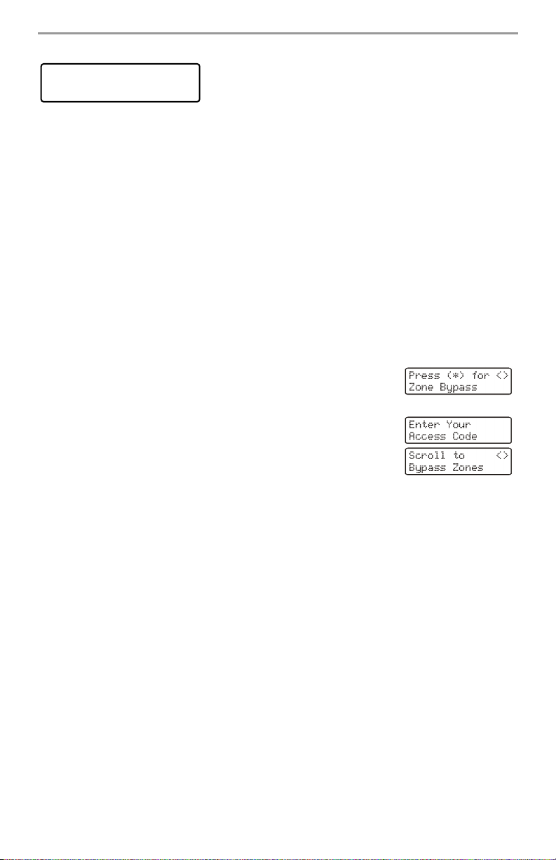
1. Press [
2. Press [1] or [].
3. If your system is programmed to require access codes the screen on
4. Scroll to the desired zone number using the [<][>] keys, then press []
] to enter the function menu. The keypad will display the
screen on the right.
the right will be displayed. Enter your 4-digit access code.
to select the zone or directly enter the 2-digit number of the zone
you wish to bypass (e.g., 0 5 for zone 5).
Activating All Bypassed Zones
To remove bypass (all zones):
1. Press [
2. Press [0][0].
3. To exit bypassing mode and return to the Ready state, press [#].
Recalling Bypassed Zones
To recall the last set of bypassed zones:
1. Press [][1], then your access code.
2. Press [9][9].
3. To exit bypassing mode and return to the Ready state, press [#].
][1], then your access code.
9.1 Bypass Group
A Bypass Group is a selection of zones programmed into the system. If you bypass a group of zones
on a regular basis, you can program them into a Bypass Group, so that you do not have to bypass
each zone individually. Note that only one Bypass Group can be programmed at a time.
To program a Bypass Group:
1. Press [][1], then enter your access code.
2. Enter the 2-digit number (01-64) of the zone to be included in the Bypass Group or use the [<][>]
buttons to scroll through the available zones. Press [] to select the zone.
3. To save the selected zone into the group, press [9][5].
4. To exit bypassing mode and return to the Ready state, press [#].
5
 Loading...