

Impact Subsea ISM3D Installation & Operation Manual
www.impactsubsea.com
Innovative Underwater Products
ISM3D
Heading, Pitch & Roll Sensor
Installation & Operation
Manual
Revision: 1.2
Date: 09/01/19
Impact Subsea Ltd
T. +44 (0) 1224 460 850
E. info@impactsubsea.co.uk
W. www.impactsubsea.com

Contents
1.0 Introduction.................................................................................................................................3
2.0 Specification................................................................................................................................4
2.1 Unit Overview .................................................................................................................4
2.2 Unit Dimensions..............................................................................................................4
2.3 Attitude & Heading Reference System............................................................................5
2.4 Communications, Power & Physical...............................................................................5
3.0 Overview.....................................................................................................................................6
4.0 Installation .............................................................................................................................7
4.1 Location............................................................................................................................7
4.1.1 Magnetic Disturbers (For Heading Accuracy).....................................................7
4.1.2 Alignment with Vehicle (For Pitch/Roll Accuracy)...............................................7
4.2 Mounting .........................................................................................................................9
4.3 Electrical .......................................................................................................................10
4.3.1 Connector Pin Out..............................................................................................10
4.3.2 Power..................................................................................................................11
4.3.3 Serial Interface....................................................................................................11
4.3.4 RS232 Wiring.....................................................................................................11
4.3.5 RS485 Wiring.....................................................................................................12
4.3.6 Establishing Communications............................................................................13
4.3.7 Connector Mating...............................................................................................13
4.3.8 Connector Cleaning............................................................................................13
5.0 Operation ..................................................................................................................................14
5.1 Use With seaView Software...........................................................................................14
5.2 Integration With Systems...............................................................................................15
5.3 ISM3D Setup..................................................................................................................15
5.4 Magnetic Calibration......................................................................................................18
6.0 ASCII Output Strings ...............................................................................................................23
6.1 AHRS.............................................................................................................................23
7.0 Servicing....................................................................................................................................26
8.0 Warranty....................................................................................................................................27
9.0 Technical Support .....................................................................................................................28
Every effort is made to ensure that information within this document is up to date. However, information within this
document is subject to change without notice, in-line with our commitment to continuous product development and
improvement.

www.impactsubsea.com
Innovative Underwater Products
1.0 Introduction
The ISM3D sensor is a compact and highly accurate Attitude and Heading
Reference System providing Heading, Pitch & Roll.
Suitable for a large range of underwater applications, the ISM3D can be used with
ROVs, AUVs, Hydro-graphic Survey, Construction, Positioning and any other
application where accurate Heading, Pitch & Roll is required underwater.
The Heading, Pitch and Roll readings are provided from integrated Micro Electro
Mechanical Systems (MEMS) based Magnetometers, Accelerometers and
Gyroscopes. The outputs of each MEMs based device are fused together to provide
highly accurate and stable Heading, Pitch and Roll measurements.
Using the Inertial Heading mode, the ISM3D also provides a high resilience against
temporary magnetic interferers. This enables successful prolonged operation
alongside steel structures where required.
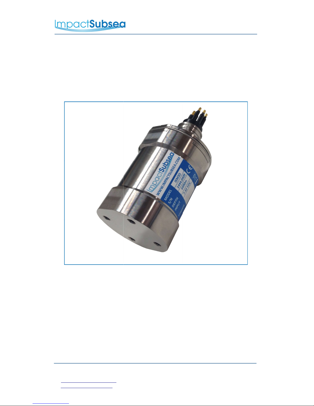
Housed in a compact and lightweight Titanium or Delrin® housing ensures that the
ISM3D is not only at the forefront of sensor technology; but is built to withstand the
most extreme underwater environments.
ISM3D Attitude & Heading Reference System (Titanium)
© Impact Subsea Ltd 3
www.impactsubsea.com
Innovative Underwater Products
2.0 Specification
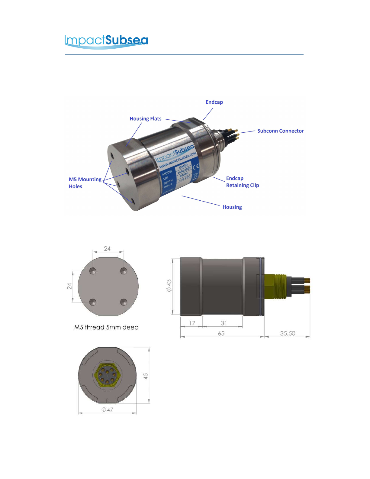
2.1 Unit Overview
2.2 Unit Dimensions
All dimensions are in mm.
© Impact Subsea Ltd 4

www.impactsubsea.com
Innovative Underwater Products
2.3 Attitude & Heading Reference System
Heading Attitude
Accuracy ± 0.5° of Magnetic
North
Pitch ± 90°
Roll ± 180°
Resolution 0.01° Accuracy ± 0.07°
Resolution 0.01°
2.4 Communications, Power & Physical
Communications & Power Physical
Digital RS232 & RS485 Weight
(Air/Water)
Titanium: 0.33/ 0.225kg
Delrin: 0.20 / 0.10kg
Protocol 300 to 115,200
baud
Depth Rating Titanium: 6,000 meters
Delrin: 1,000 meters
Data Continuous or on
demand
Temperature Operating: -10 to 50°
Storage: -20 to 70°
Data Rate Up to 250Hz Connector Subconn MCBH8M-SS
fitted as standard
Input Voltage 7 to 32V DC
Power 29mA @ 24V DC
© Impact Subsea Ltd 5

www.impactsubsea.com
Innovative Underwater Products
3.0 Overview
The ISM3D is a highly compact, robust and accurate underwater Attitude & Heading
Reference System (AHRS).
The ISM3D is depth rated to 1,000 meters (Delrin®) or 6,000 meters (Titanium).
The Heading, Pitch and Roll readings are provided by a Micro-Electro-Mechanical
system (MEMS) based technology. MEMs based Gyros, Accelerometers and
Magnetometers are integrated within the unit.
The outputs from each MEMS based sensor are processed by an advanced fusion
algorithm to provide highly stable and accurate Heading, Pitch & Roll.
For optimal heading performance, a hard and soft iron calibration can be performed
on the unit once installed on the ROV, AUV or other underwater platform. This
ensures that a consistently accurate heading is provided at all times.
In areas where a large amount of steel or other magnetic disturber is present, the unit
can be switched to Inertial mode. Inertial mode operates using the Angular Rate
Gyroscopes and Accelerometers, without input from the Magnetometer. The low drift
rate of the MEMS based Gyroscopes enables navigation to be conducted in areas
where previously only a fibre or ring laser diode based heading sensor would suffice.
The ISM3D can be configured using the supplied seaView software. seaView allows
all settings to be configured (output strings, communications protocol, baud rate etc).
In addition to allowing the ISM3D to be configured, seaView also allows all outputs to
be viewed in real time and logged.
© Impact Subsea Ltd 6

www.impactsubsea.com
Innovative Underwater Products
4.0 Installation
4.1 Location
When evaluating the installation location of the ISM3D, there are several
factors to consider to achieve optimum operation from each part of the
unit:
– Magnetic Disturbers (Heading)
– Alignment with Vehicle (Pitch/Roll)
4.1.1 Magnetic Disturbers (For Heading Accuracy)
Where the heading output is to be used, the ISM3D should be mounted as
far as possible from sources of magnetic interference.
Electrical items which can cause magnetic interference include motors,
transformers and valve packs.
Ferrous metals, or any other magnetically active materials will also have
influence on the heading reading. Thus, where possible, the unit should be
installed as far as possible from magnetically active materials.
A magnetic calibration should be conducted using the seaView software once
the unit is physically installed.
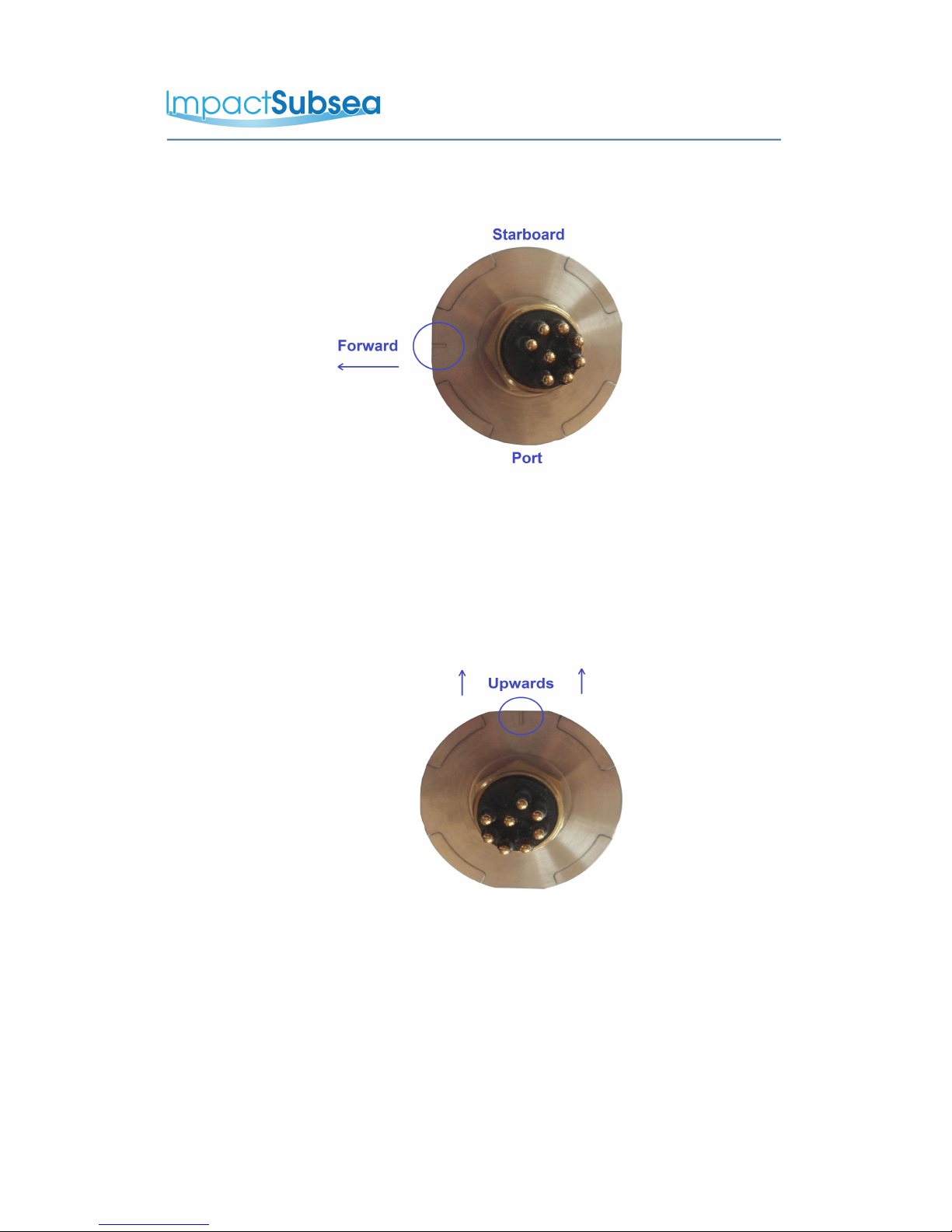
4.1.2 Alignment with Vehicle (For Pitch/Roll Accuracy)
When mounting vertically, the ISM3D should be mounted with the
base (complete with mounting screw holes) facing downwards (to the
seabed) and the indentation in the connector end cap pointing forwards, in
the direction of forward vehicle travel:
© Impact Subsea Ltd 7
www.impactsubsea.com
Innovative Underwater Products
When mounting horizontally the ISM3D should be installed with the
indentation in the connector end cap pointing upwards:
© Impact Subsea Ltd 8
www.impactsubsea.com
Innovative Underwater Products
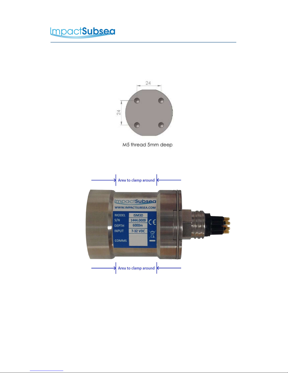
4.2 Mounting
The ISM3D should be mounted using four M5 Screws, screwed into the base
of the unit:
Alternatively the unit has a 31mm recess in the main body to enable a
clamp to be tightened securely around the unit:
Ideally a non-metallic clamp should be used, however in the event that this is
not possible, effort should be made to electrically isolate the clamp from the
ISM3D housing. This can be achieved by using rubber or plastic strips
around the body of the ISM3D.
The ISM3D has two flats, on either side of the body – these are to enable
the unit to sit tightly against another flat surface if available.
© Impact Subsea Ltd 9
 Loading...