

Page 1
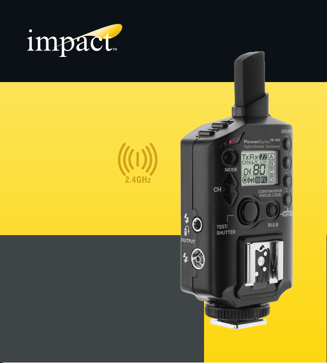
2.4 GHz 80-Channel
2.4GHz
Transceiver
PS-80
PowerSync 16-80
Transceiver
INSTRUCTIONS
1
Page 2

Table of Contents
Introduction ...........................................................................................................3
Key Features .......................................................................................................4-5
Contents ................................................................................................................5
Device Layout / LCD ............................................................................................6-7
Precautions ............................................................................................................8
Installing the Batteries ...........................................................................................9
Mode Selection ....................................................................................................10
Channel Selection ................................................................................................11
Groups ............................................................................................................12-13
Compatible Devices / Backwards Compatibility ..............................................14-15
Using the Transceiver with Your Flash.............................................................16-19
Using Your Transceiver as a Shutter Release .................................................20-28
Advanced Features ........................................................................................29-33
Troubleshooting ...................................................................................................34
Specifications .....................................................................................................35
FCC Compliance ..................................................................................................35
Warranty ............................................................................................................36
2
Page 3

Introduction
Congratulations on the purchase of your Impact PowerSync 16-80 Transceiver.
This multi-purpose 2.4 GHz 80-channel digital wireless transceiver empowers
users to remotely trigger flash and camera devices. With the use of a minimum
of two PowerSync 16-80 units, you can enjoy the freedom of triggering from a
distance up to 720 feet (220 m).
The PowerSync 16-80 was designed to give photographers an easy to use,
high-quality radio slave system. The wireless control capability eliminates the
presence of cable clutter, making it ideal for studio or outdoor flash scenarios.
Remote triggering is a secondary ability of the PowerSync 16-80. This is helpful
when a subject, such as wildlife, may be difficult to approach. Additionally, the
wireless function of the device removes the potential of camera shake, making it
ideal for macro, close-up, and long exposure photography.
The PowerSync 16-80’s grouping and range-extending functions create easy to
control transitioning between pre-set devices for off-camera and long-distance
triggering. The adaptive PowerSync 16-80 is also backwards compatible with
the PowerSync 16, enabling owners to use the PowerSync 16-80 with their older
units. One PowerSync unit is able to wirelessly trigger many compatible units.
Its small size and included pouch make the PowerSync 16-80 simple to store and
transport.
To fully understand and best use the functions and capabilities of your PowerSync
16-80, please take a moment to read through this user guide.
3
Page 4

Key Features:
•DigitalWirelessTransceiver: Powerful multipurpose transmitter/receiver
that can act as a flash trigger and remote shutter release for multiple devices
simultaneously.
•SyncSpeed: Offers a maximum sync speed of 1/250 second, allowing the user
to capture images wirelessly in most shooting scenarios.
•80DigitalChannels: Perfect for operating multiple devices wirelessly without
having to worry about radio or flash interference.
•DigitallyCoded2.4GHzSignal:A stronger and more reliable radio signal that
allows the units to communicate, even with barriers between them, eliminating
the need for a line-of-sight between devices.
•BackwardCompatibility: Compatible with the Impact PowerSync 16
transmitter and receiver units.
•FourIndividualGroupings: Provides the user with the ability to wirelessly
bundle multiple units in bunches, creating separate groups with alternate
settings.
•IdealforLong-ExposureandMacroPhotography:The hands-free shutter
release features of the device make it perfect for photography situations where
eliminating camera shake is an asset.
4
Page 5
•ExtendedWirelessRange: Has the ability to extend the device’s signal range
1
PS-80
PowerSync 16-80
Transceiver
INSTRUCTIONS
2.4 GHz 80-Channel
Transceiver
2.4GHz
with the use of multiple units for flash and camera triggering.
•Auto-Syncing: This synchronizes your remote flashes with a camera’s shutter
release using only three transceiver units.
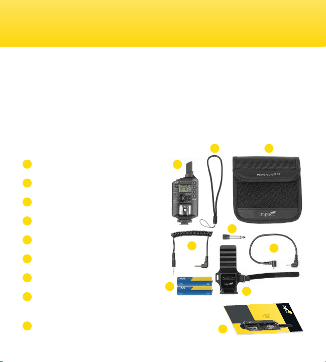
Contents Include
1
Transceiver
2
Lanyard
3
Pouch
4
3.5 mm to 3.5 mm flash sync cable
5
3.5 mm to 1/4” cable adapter
6
2.5 mm to PC flash sync cable
7
2x AA alkaline batteries
8
Self adhesive, adjustable
accessory shoe
9
User guide
2 3
1
5
4
7
6
8
9
5
Page 6
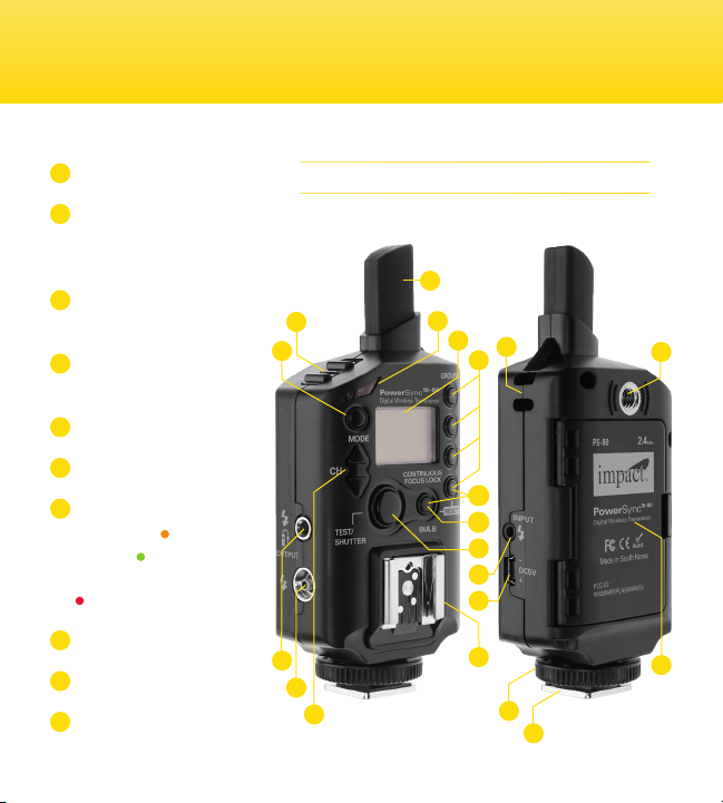
Overview
1
Power switch
2
Mode (Transmitter
TX, Receiver RX, or
Transceiver TX/RX)
3
3.5 mm output for flash/
shutter release cable
4
Female screw-in PC
port output
5
Channel selector
6
Integrated antenna
7
LED status light
Auto focus: orange
Shutter: green
Power on confirmation:
blinking red
8
Backlit LCD screen
9
Group selector
10
Lanyard loop connection
6
Device Layout
6
1
2
3
4
5
7
8
10
9
11
12
13
14
15
16
17
18
20
19
Page 7
11
Reset (Press “Bulb”
and Group “D” button
for 3 seconds)
12
Bulb mode/Continuous
focus lock
13
Test (flash)/Shutter
Release Button
(shutter)
14
2.5mm PC input
15
mini-USB Type B/DC5v
adapter port
16
Receiver hot shoe
mount
17
Locking thumbwheel
18
Transmitter shoe foot
19
Battery compartment
20
¼-20” female threaded
socket
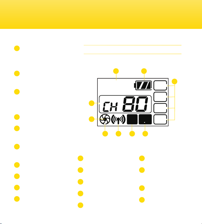
TxRx
ON LY
22
23
21
Tx/Rx mode indicator
22
Channel indicator
23
Shutter indicator
24
Focus confirmation
25
Signal verification
LCD
2921
LOW
B
FL
27262524
26
Bulb mode indicator
27
Continuous focus
lock indicator
28
Group indicator
29
Battery status
28
A
B
C
D
7
Page 8

Precautions
• There are no user-serviceable parts inside the devices. Do not attempt to disassemble
or perform any unauthorized modification.
• Do not operate the PowerSync 16-80 in the presence of flammable gas or vapors.
• Do not handle with wet hands or immerse in or expose to water or rain. Failure to
observe this precaution could result in fire or electric shock.
• Keep out of the reach of children. This device contains small parts which may pose a
choking hazard.
• Observe caution when handling batteries. Batteries may leak or explode if improperly
handled. Use only the batteries listed in this manual. Make certain to align batteries
with the correct polarity.
• Batteries are prone to leakage when fully discharged. To avoid damage to the product,
be sure to remove the batteries before leaving the product unattended for prolonged
periods or when no charge remains.
• Do not use or leave the devices in conditions of extreme heat, severe cold, or high
humidity.
• Turn off the camera and/or flash’s power before inserting or removing any cord.
• Dispose of used batteries, packaging, and old devices in accordance with appropriate
local environmental regulations.
• All images are for illustrative purposes only.
8
Page 9
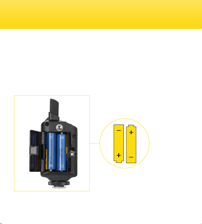
Installing the Batteries
The battery compartment is located on the rear of the device. To install the
batteries, open the compartment door and carefully slide two AA batteries into
position. Ensure that the polarity of the batteries match the icons shown within
the compartment.
The PowerSync 16-80 may also be powered using a mini-USB type B DC5v AC
adapter.
9
Page 10

Mode Selection
Transmitter(Tx:)
Transmitter mode sets the transceiver to only send out signals to other devices.
No incoming signals will affect the device while this mode is initiated.
Receiver(Rx):
Receiver mode sets the transceiver to only accept incoming signals from
transmitting devices. This mode does not allow the device to send out signals.
Transmitter/Receiver(Tx/Rx):
Transmitter/Receiver mode allows the transceiver to both send and receive
signals to or from other devices simultaneously.
To change the mode on your PowerSync 16-80, press and hold the M button until
the current mode begins to blink on the LCD screen. Press the M button again
until your desired mode is displayed on the LCD screen.
NOTE: Using Tx/Rx mode increases the chance of signal interruptions between
communicating devices in the presence of many PowerSync 16-80 units. For the
most reliable signal transmission or reception, use either Tx or Rx mode when
possible.
10
Page 11

Channel Selection
The Impact PowerSync 16-80 provides the user with 80 individual channels. To
set a device’s channel, push and hold the Channel Selector buttons, up or down,
for two seconds until the channel number begins to blink. Press the Channel
Selector buttons up or down to select the desired channel number.
11
Page 12

Compatible Devices
The PowerSync 16-80 does not transmit TTL (through-the-lens) settings. A flash,
with full manual output control is required for use with this device. Most manual
flashes are compatible with the PowerSync 16-80’s receiver hot-shoe mount.
Ones that are not are the Sony/Minolta, Sony Multi-Interface, and Pentax flashes.
The hot-shoe foot is compatible with all hot-shoe cameras except for Sony/
Minolta and Pentax.
Backwards Compatibility
The PowerSync 16-80 is backward compatible with the PowerSync 16 Radio
Slave System.
PowerSync16TransmittertoPowerSync16-80asReceiver:
The PowerSync 16 transmitter can be used to trigger the PowerSync 16-80. Set
your PowerSync 16-80 to Receiver (Rx) or Transmitter/Receiver (Tx/Rx) mode
using the M button to accept a signal from the PowerSync 16 transmitter. Ensure
the channel on both devices is identical. See chart below.
PowerSync16-80TransmittertoPowerSync16asReceiver:
The PowerSync 16-80 can be used to trigger the PowerSync 16 receiver. Set your
PowerSync 16-80 to Transmitter (Tx) or Transmitter/Receiver (Tx/Rx) mode using
12
Page 13

the M button to send a signal. Ensure the channel on both devices is identical.
See chart below.
For channel selection, the PowerSync 16 system relies on manual channel
selector switches. Despite the PowerSync 16-80’s digital interface, channels on
the two devices can be synchronized using the chart below as a guide:
Note: When using the PowerSync 16 – only 16 channels are available.
The PowerSync 16-80’s backward compatibility with the PowerSync 16 system
will only work if No Group is selected on the PowerSync 16-80.
13
Page 14

Using the Transceiver with Your Flash
Connecting the Transceiver to Your Flash
A transceiver is a device comprising both a transmitter and a receiver combined to share
common circuitry or a single housing.
MountingtheTransceiver(Transmitter):
OnaCamera: With all of the devices
turned off, slide the transceiver onto your
camera’s hot-shoe mount. Tighten the
locking ring to secure.
14
OnaBracket: With all of the devices
turned off, slide the transceiver onto the
bracket’s cold shoe-mount. Connect the
devices with the included 2.5 mm to PC
cable, with the 2.5 mm end inserted in the
transceiver’s input. Then plug the PC end of
the cable into your camera’s PC port.
Page 15

MountingtheTransceiver(Receiver):
ToaLightStand: With all devices turned
off, mount the transceiver to a light stand
using the threaded 1/4”-20 socket located
on the back of the device. Turn the device
clockwise until secure. Slide your hot-shoe
flash into the transceiver’s hot shoe.
Power on the flash, both transceiver units
(transmitter and receiver) and your camera.
Synchronize the channel and group settings
on both transceivers. Push the on-camera
transceiver’s Test button or the camera’s
on-body shutter release button to trigger
the lights.
NOTE: Many modern flashes and cameras have a Sleep mode. This must be turned off before
using with the PowerSync 16-80. Refer to your flash or camera manual for instructions.
ToaStudioMonolightFlash: With all of
the devices turned off, connect and secure
the receiving (on-strobe) transceiver to the
studio strobe. Among other ways, this can
be done using the included lanyard strap or
supplied adhesive-backed hot-shoe mount.
The backing of the mount can be trimmed
as necessary.
Connect the studio strobe to the on-strobe
transceiver using the appropriate to 3.5 mm
output sync [ ] port.
15
Page 16

Using the Transceiver with Your Flash
Wireless Remote Triggering with Hot-Shoe Flash
The wireless functionality of the PowerSync 16-80 requires the user to have two units (one
transmitting transceiver, one receiving transceiver) to operate.
1.Turn on the receiving (on-flash) transceiver and set it to Receiver (Rx) or Transmitter/
Receiver (Tx/Rx) mode using the M button.
2.Turn on the on-camera transceiver and set it to Transmitter (Tx) or Transmitter/Receiver
(Tx/Rx) mode.
3.Make sure the same channel and group settings are selected on each of the transceiver
units.
4.Turn on all your devices, push the on-camera transceiver’s Test button or the camera’s
shutter trigger to activate the flash and camera devices.
NOTE: When the on-camera hot shoe is occupied, connect your
transceiver to your camera via the included PC sync cable.
16
Page 17

Wireless Remote Triggering with Studio Strobe
1.With all of the devices turned off, connect and secure the receiving (on-strobe)
transceiver to the studio strobe. Among other ways, this can be done using the included
lanyard strap or supplied adhesive-backed hot-shoe mount. The backing of the mount
can be trimmed as necessary.
2.Connect the studio strobe to the on-strobe transceiver using the appropriate cable to the
3.5 mm output sync [ ] port.
3.Turn on the camera, studio flash, and transceiver units.
4.Set the on-camera transceiver to Transmitter (Tx) or Transmitter/Receiver (Tx/Rx) mode
using the M button.
5.Set the on-strobe transceiver to Receiver (Rx) or Transmitter/Receiver (Tx/Rx) mode
using the M button.
6.Select and match the channel and group settings on the transceivers.
7.Trigger the studio strobe by pushing the on-camera shutter release button or the on-
camera transceiver’s Test button
If your studio light has a 1/4” phono jack, you will need to use the included 3.5mm to 1/4”
phono adapter. Additional sync cables are available separately.
17
Page 18

Groups
Group Selection
The group functionality of the Impact PowerSync 16-80 Transceiver allows the
user to control up to four separate groups of flashes or cameras (Group A, B,
C, and D). All the receiver(s) matching the group selected on the transmitter
will receive a signal. Simultaneous triggering of multiple light or camera groups
requires additional transceivers (available separately).
To assign your device(s) to a group, simply press and hold the A, B, C, or D
button for one second. The corresponding letter will be displayed on the screen.
To unassign a unit, hold the same group button for one second. The on-screen
group indicator will no longer appear.
Using Groups
A group consists of a minimum of one device or as many devices that are
necessary for the application. Using groups allows you to easily configure up to
four different light or camera groups. You can select any one group individually,
or in combination with any other of the groups, to achieve a particular lighting or
camera exposure effect.
Various lighting configurations are used to achieve different effects. Here’s a
typical multi-group lighting example:
18
Page 19

GroupA: Key light(s) – the main
and most important light
in the composition of a
photograph.
D
B
GroupB: Background light(s) –
used to illuminate the
background lighting of a
composition.
A
GroupC:Fill light(s) – used to fill
or lighten shadows in a
composition.
C
GroupD: Hair/Accent light(s) – used
to emphasize an area or
object in a composition.
Note: Once you have made your selection, the PowerSync 16-80 will remember
your setting selection of Mode, Channel, Group even when turning the unit on /off,
making it easy to start your next session at the same settings.
Defaultsetting: Returning the unit to factory defaults Press “Bulb” and Group “D”
button for 3 seconds, unit will return to factory defaults which are:
Mode TX/RX Channel 1 Groups No groups selected
Note: Use the All Groups off (No Group) setting if you plan to use with a
PowerSync 16 or without the intent of individual on/off group control.
19
Page 20

Using Your Transceiver as a Shutter Release
The PowerSync 16-80 transceiver can be used to trigger your camera. The
release functionality of the PowerSync 16-80 only requires the use of one transceiver
device. The
(one transmitting transceiver, one receiving transceiver) to operate.
Camera compatibility and camera specific remote shutter release cables are available
separately. See included flyer for camera and shutter release cable
compatibility list.
wireless
functionality of the PowerSync 16-80 requires you to have two units
wired
shutter
Using the Transceiver as a Wireless Shutter Release
SingleShot:
1.With all devices turned off, connect and secure the receiving (on-camera) transceiver
to the camera by plugging the camera dedicated shutter release cable into the Camera
remote [ ] port and the other 3.5mm end into the transceiver’s output port [ ].
2.Turn on the on-camera transceiver and set it to Receiver (Rx) mode using the M button.
3.Turn on the transmitting (in-hand) transceiver and set it to Transmitter (Tx) mode using
the M button.
4.Synchronize the group and channel selection on both devices.
5.Turn on your camera and set your camera to single-shot mode.
20
Page 21

6.Half press the Shutter Release button on the in-hand transceiver to auto-focus the
camera.
7.Fully press the Shutter Release button on the in-hand transceiver to activate the camera’s
shutter.
ContinuousShooting:
1.With all devices turned off, connect and secure the receiving (on-camera) transceiver
to the camera by plugging the camera dedicated shutter release cable into the Camera
remote [ ] port and the other 3.5mm end into the transceiver’s output [ ].
2.Turn on the on-camera transceiver and set it to Receiver (Rx) mode using the M button.
3.Turn on your camera and set it to continuous shooting mode at a shutter speed higher
than Bulb.
4.Turn on the in-hand transceiver and set it to Transmitter/Receiver (Tx/Rx) mode using the
M button.
5.Synchronize the group and channel selection on both devices.
6.Half press the shutter release button on the in-hand transceiver to auto-focus the camera.
7.Push and hold the Shutter Release button on the in-hand transceiver to trigger the
continuous firing mode on the camera.
8.Release the button to stop continuous shooting.
21
Page 22

Using Your Transceiver as a Shutter Release
Using Wireless Bulb Mode
Option1:Press/Hold Exposure
1.With all devices turned off, connect and secure the receiving (on-camera) transceiver
to the camera by plugging the camera dedicated shutter release cable into the Camera
remote [ ] port and the other 3.5mm end into the transceiver’s output [ ].
2.Turn on your camera and set it to Bulb.
3.Turn on the on-camera transceiver and set it to Receiver (Rx) mode using the M button.
4.Turn on the in-hand transceiver and set it to Transmitter (Tx) mode using the M button.
5.Synchronize the group and channel selection on both devices.
6.Half-press the Shutter Release button to auto-focus the camera.
7.Using the in-hand transceiver, push and hold the Shutter Release button to open the
camera’s shutter.
8.Release the button when the desired exposure time has elapsed.
22
Page 23

Option2:Two-Click Exposure
1.With all devices turned off, connect and secure the receiving (on-camera) transceiver
to the camera by plugging the camera dedicated shutter release cable into the Camera
remote [ ] port and the other 3.5mm end into the transceiver’s output [ ].
2.Turn on your camera and set it to Bulb.
3.Turn on the on-camera transceiver and set to Receiver (Rx) mode using the M button and
bulb mode by holding the Bulb Mode button. The LCD display will display a “B” symbol
when the function is activated.
4.Turn on the transmitting (in-hand) transceiver and set it to Transmitter/Receiver (Tx/Rx)
mode using the M button and Bulb (B) mode using the Bulb button. The LCD display will
continuously flash a “B” to indicate when the function has been activated.
5.Synchronize the group and channel selection on both devices.
6.Half-press the Shutter Release button to auto-focus the camera.
7.Push the Shutter Release button to open the camera’s shutter. A synchronized timer will
appear on both transceiver screens indicating the elapsed time.
8.Push again to close the camera’s shutter.
9.Push Bulb button twice to turn off “B” mode.
23
Page 24

Using Your Transceiver as a Shutter Release
Using the Transceiver as a Wired Shutter Release
A wired connection to the camera only requires one PowerSync 16-80 device. It allows the
user to stay by the camera without having to trigger it with the camera’s shutter release
button, avoiding camera shake.
SingleShot:
1.With all devices turned off, connect the receiving (on-camera) transceiver to the camera
by plugging the camera dedicated shutter release cable into the Camera remote
[ ] port and the other 3.5mm end into the transceiver’s output [ ]. (Attach the
Transceiver to the camera by using the lanyard or a cold shoe bracket)
2.Turn on the transceiver and set it to Transmitter (Tx) or Transmitter/Receiver (Tx/Rx)
mode using the M button.
3.Turn on your camera and set your camera to single-shot mode.
4.On the transceiver, half press the Shutter Release button to auto-focus the camera.
5.Fully press the Shutter Release button to activate the camera’s shutter.
24
Page 25

ContinuousShooting:
Option1:Press/HoldContinuousShooting
1.With all devices turned off, connect the receiving (on-camera) transceiver to the camera
by plugging the camera dedicated shutter release cable into the Camera remote
[ ] port and the other 3.5mm end into the transceiver’s output [ ]. (Attach the
Transceiver to the camera by using the lanyard or a cold shoe bracket)
2.Turn on your camera and set it to continuous shooting mode. Make sure to set your
camera to any shutter speed other than Bulb.
3.Turn on the transceiver and set it to Transmitter/Receiver (Tx/Rx) mode using the M
button.
4.On the transceiver, half press the Shutter Release button to auto-focus the camera.
5.Fully press and hold the Shutter Release button to activate the camera’s shutter.
6.Release the button to stop continuous shooting.
25
Page 26

Using Your Transceiver as a Shutter Release
Option2:Two-ClickContinuousShooting
1.With all devices turned off, connect and secure the transceiver to the camera by plugging
the camera dedicated shutter release cable into the Camera remote [ ] port and the
other 3.5mm end into the transceiver’s output [ ]. (Attach the Transceiver to the
camera by using the lanyard or a cold shoe bracket)
2.Turn on your camera and set it to continuous shooting mode. Make sure to set your
shutter speed to any other than Bulb.
3.Turn on the transceiver and set it to Transmitter/Receiver (Tx/Rx) mode using the M
button. Next, activate the transceiver’s Bulb mode by holding down the Bulb Mode
button. The LCD display will flash a B to indicate when the function has been activated.
4.On the transceiver, half press the Shutter Release button to auto-focus the camera.
5.Fully press the Shutter Release button to activate the camera’s shutter. A timer will
appear on the LCD panel displaying the time elapsed.
6.Press the button again to stop continuous shooting.
7.Push Bulb button twice to turn off “B” mode.
26
Page 27

Using Wired Bulb Mode
Option1:Press/Hold Long Exposure
1.With all devices turned off, connect and secure the transceiver to the camera by plugging
the camera dedicated shutter release cable into the Camera remote [ ] port and the
other 3.5mm end into the transceiver’s output [ ]. (Attach the Transceiver to the
camera by using the lanyard or a cold shoe bracket)
2.Turn on your camera and set it to Bulb.
3.Turn on the transceiver and set it to Transmitter/Receiver (Tx/Rx) mode using the M
button.
4.On the transceiver, push and hold the Shutter Release button to open the camera’s
shutter.
5.Release the button when the desired exposure time has elapsed.
27
Page 28

Using Your Transceiver as a Shutter Release
Option2:Two-Click Long Exposure
1.With all devices turned off, connect and secure the transceiver to the camera by plugging
the camera dedicated shutter release cable into the Camera remote [ ] port and the
other 3.5mm end into the transceiver’s output [ ]. (Attach the Transceiver to the
camera by using the lanyard or a cold shoe bracket)
2.Turn on the camera and set it to Bulb.
3.Push Bulb button twice to turn off “B” mode.
4.Push the Shutter Release button to open the camera’s shutter. A timer will appear on the
LCD panel displaying the elapsed time.
5.Push again to close the camera’s shutter.
6.Push Bulb button twice to turn off “B” mode.
28
Page 29

Advanced Features
Auto-Sync Triggering for Cameras and Flashes
The PowerSync 16-80 includes an auto-sync triggering function. This synchronizes your
remote flashes with a camera’s shutter release using only
you can trigger both your camera and flash wirelessly using three transceivers.
To set up your devices for the auto-sync triggering mode, please use the following
instructions:
1.Turn on the transmitting (in-hand) transceiver and set it to Transmitter (Tx) or Transmitter/
Receiver (Tx/Rx) mode using the M button and select a channel and group.
2.With the device turned off, connect the second (on-camera) transceiver device to the
camera using the camera dedicated shutter release cable into the shutter release [ ]
port. Install and secure the device to your camera’s hot shoe.
3.Turn the on-camera transceiver on and set it to Transmitter/Receiver (Tx/Rx) mode using
the M button. Match the unit’s channel and group to that of the transmitting (in-hand)
transceiver.
4.With the third (on-flash) transceiver off, connect and secure it to the remote flash (See
Page 14 for mounting to flash instructions). Once this is completed, turn it on.
5.Set the (third) on-flash transceiver to Receiver (Rx) mode using the M button. Set it to
one channel above that of the first two units. For example, if the in-hand and on-camera
three
transceiver units, meaning
29
Page 30

Advanced Features
transceivers are set to Channel 1,
the on-flash unit should be set to
Channel 2. Ensure the selected group
matches the first two units.
6.Half-press the transceivers shutter
release button to auto-focus the
camera, then press and release
the Shutter Release button on the
in-hand transceiver to fire the remote
camera and flash. The remote flash
will synchronize with the camera
automatically.
The following chart illustrates the modes that differently purposed devices need to be set to
while using the auto-sync triggering function:
Device Applicable Modes
In-Hand Transmitter (Tx), Transmitter/Receiver (Tx/Rx)
On-Camera Transmitter/Receiver (Tx/Rx)
On-Flash Receiver (Rx), Transmitter/Receiver (Tx/Rx)
In-Hand
(Tx or Tx/Rx
Channel 1)
On-Camera
(Tx/Rx
Channel 1)
On-Flash
(Rx or Tx/Rx
Channel 2)
30
Page 31

Using the Continuous Focus Lock Function
The PowerSync 16-80 allows the user to minimize the lag time between when the
photographer presses the Test/Shutter release button of the PS16-80 and the camera
achieves autofocus and the shutter is actually released.
By pressing the Continuous Focus Lock button on the PS16-80 when used as a receiver,
the PS16-80 focus locks the camera’s focus mechanism to continuously focus. Equivalent
to constantly half-pressing the camera’s shutter release button, the Continuous Focus Lock
button does it for you, constantly engaging the camera’s autofocus mechanism until the
Continuous Focus Lock button is turned off.
1.With all devices turned off, connect and secure the receiving (on-camera) transceiver to
the camera, and by plugging the camera dedicated shutter release cable into the Camera
remote [ ] port and the other 3.5mm end into the transceiver’s output [ ].
2.Turn on and set the on-camera transceiver to Receiver (Rx) mode using the M button.
3.Turn on the camera and transmitting (in-hand) transceiver. Set the transceiver to
Transmitter (Tx) mode using the M button.
4.Ensure that your camera is set to both AutoFocus and Continuous Focus mode. (AF-C on
Nikon, AI-Focus or AI-Servo on Canon)
5.Push the Continuous Focus Lock button on the on-camera transceiver two times to set
FocusLock. The LCD will blink “FL” to indicate that the continuous focus is locked.
31
Page 32

Advanced Features
6.When you’re ready to trigger the camera, press the shutter release button on the in-hand
transceiver.
7.To disable the function, push the Continuous Focus Lock button again. The on-screen
indicator (FL) will disappear.
Summary:
• With your camera set to Autofocus
• With your camera set to Continuous Focus Mode
• PS16-80 attached to camera via 3.5mm to camera specific cable
• With your camera set to a higher speed than bulb.
ContinuousFocusLockON
• Camera Continuously focuses and meters
• Minimal lag time between when camera achieves autofocus and when camera
actually fires
• Some Camera menus are no longer available
ContinuousFocusLockOFF
• Camera focuses and meters only when Test/Shutter button is pressed
• Lag time between when camera achieves focus and camera fires
• All Camera menus are available
32
Page 33

Extending the Wireless Range
The PowerSync 16-80 transceiver has the ability to extend the device’s signal range with
the use of multiple units for flash and camera triggering.
For example, the PowerSync 16-80’s maximum operating range is up to 720 feet (220
meters). If a second unit is placed just before that maximum range in Transmitter/Receiver
(Tx/Rx) mode, it would extend the range of the first (transmitting) unit up to a maximum
1,440 feet (440 meters) in that direction. This will allow a third unit to be placed within that
extended range (in Rx mode) and receive the trigger signal from the first unit. This process
can be repeated to extend the range even further.
Up to 720’ range Up to 720’ range
In-Hand
(Tx or Tx/Rx)
On Light Stand
(Tx/Rx)
On-Camera
(Rx or Tx/Rx)
33
Page 34

Troubleshooting
• Check that channels and groups on all
communicating devices are identical
(except when using the Auto-Sync
advanced feature). When turning on
the unit, it is important to review and, if
necessary, reset the group selection.
• If your first choice of channel does not
work, try a different channel until you
find one that works.
• Ensure that all cables are installed
correctly.
• Make sure that the power source for
each device is properly installed and
carrying a sufficient charge. Weak
batteries can reduce the distance over
which a transmission works.
• If you are triggering your transceiver
with a wired connection, make sure the
device is connected using the correct
cable and the cable is connected to the
correct input port.
• Make sure that a communication
confirmation appears on the LCD
screen when sending a signal.
34
• Verify that flash and camera equipment
are operating properly.
• If in use with PowerSync 16 unit(s),
ensure that the channel configuration
is identical. Refer to the ‘Backwards
Compatibility’ section of this manual
on page 12.
• Check for a stuck Test button on all
units, including flash devices.
• Make sure the devices are within the
maximum operating range. For details,
please refer to the Maximum Operating
Range section of this manual on page 32.
If your PowerSync 16 won’t communicate
with your PowerSync 16-80, please refer to
the following troubleshooting suggestions:
• Make sure your PowerSync 16-80
transceiver is set to the default no
group setting.
• Make sure all devices are powered on
with fresh batteries.
• Ensure the channels on both devices
are identical. Visit page 11 for more
information.
Page 35

Specifications
Frequency: 2.4 GHz
Channels: 80 channels
Groups: 4 groups
Connections: PC outlet, 2.5 mm Input Port Connection, 3.5 mm shutter
release and flash (output), mini-USB Type B/DC5v connection.
Operating Range: Up to 720’ (220 m)
Sync Speed: 1/250 sec. maximum
Dimensions: 1.25 x 1.75 x 4.75” (2.5 x 3.75 x 12 cm)
Weight (Without Battery): 2.9 oz. (81 g)
Battery: 2x AA 1.5V alkaline, lithium, or NiMH batteries
NOTE: The maximum operating range of the Impact PowerSync 16-80 is up to 720’
(220 m). To maximize the operating range, position the transceivers with their antennas
pointed up and at least three feet from the ground. This will create an ideal transmitting
condition. The estimated maximum distance can be influenced and reduced by such factors
as radio frequency interference, walls, concrete, metal, water, and landscape features.
Avoid barriers between communicating devices.
FCC Compliance
This device complies with Part 15 of the FCC Rules. Operation is subject to the following
two conditions: (1) this device may not cause harmful interference, and (2) this device
must accept any interference received, including interference that may cause undesired
operation.
35
Page 36

One-Year Limited Warranty
This IMPACT product is warranted to the original purchaser to be free from defects in
materials and workmanship under normal consumer use for a period of one (1) year from
the original purchase date or thirty (30) days after replacement, whichever occurs later. The
warranty provider’s responsibility with respect to this limited warranty shall be limited solely
to repair or replacement, at the provider’s discretion, of any product that fails during normal
use of this product in its intended manner and in its intended environment. Inoperability of
the product or part(s) shall be determined by the warranty provider. If the product has been
discontinued, the warranty provider reserves the right to replace it with a model of equivalent
quality and function.
This warranty does not cover damage or defect caused by misuse, neglect, accident,
alteration, abuse, improper installation or maintenance. EXCEPT AS PROVIDED HEREIN,
THE WARRANTY PROVIDER MAKES NEITHER ANY EXPRESS WARRANTIES NOR ANY
IMPLIED WARRANTIES, INCLUDING BUT NOT LIMITED TO ANY IMPLIED WARRANY OF
MERCHANTABILITY OR FITNESS FOR A PARTICULAR PURPOSE. This warranty provides you
with specific legal rights, and you may also have additional rights that vary from state to
state.
To obtain warranty coverage, contact the Impact Customer Service Department to obtain
a return merchandise authorization (“RMA”) number, and return the defective product to
Impact along with the RMA number and proof of purchase. Shipment of the defective product
is at the purchaser’s own risk and expense.
For more information or to arrange service, visit www.impactstudiolighting.com or call
Customer Service at 212-594-2353.
Product warranty is provided by the Gradus Group.
www.gradusgroup.com
Impact is a registered trademark of the Gradus Group. © 2014 Gradus Group LLC. All Rights Reserved.
All other trademarks are the property of their respective owners GG1
36
 Loading...