

Page 1
impact
PowerSync16 Radio Slave
TM
INSTRUCTIONS
Page 2

Introduction
Thank you for cho osing the Po werSyn c Radio Slave S ystem, de signed
using t he latest technol ogy to produ ce a device tha t is simple to
opera te, while providi ng photogr aphers wi th the highe st qualit y radio
slave s ystem at an a ffordable price . The Power Sync Sys tem is
desig ned stric tly for as h units. I t cannot be used wit h hot light s or
cont inuous ligh t sources. T he PowerS ync Sys tem allows t he
phot ographer to t rigger the l ight source wirele ssly from the camer a
(t s most came ras). It can also be used t o trigger a rem ote camera
that h as an electro nic shut ter release co nnection . Remote sh utter
trig gering requ ires a compat ible moto r drive cable ( see Accessor ies).
The Po werSyn c Radio Slave S ystem is av ailable in t wo versions. The
AC 10 0-240 v olt versi on must be plugged int o a wall socket . The DC
version work s with t wo standar d AA bat teries. T he DC Receiv er will
also acce pt an AC adapt er (DC 7V-9 V/30 0mA) . The Transmi tter can be
used fo r either mo del and operates on one 3 V CR24 50 bat tery. You
must h ave both a Trans mitter a nd either model of Rec eiver for th e
sys tem to work . Your Transmitter ca n trigger as many Receiv ers as
you wan t. As long a s all Receiver s are with in range, and ar e set to the
same fr equency as th e Trans mitter, y our Transmit ter can tri gger as
many lights as y our setup re quires.
In orde r to fully un derstan d your new Powe rSync Rad io Slave Sys tem,
please t ake a moment t o read through this user guide .
2
Page 3

Key FeaturesSpecications
• 16 Reliable Channels: Digit ally coded a t 2.4 GHz fo r multiple
setu ps; work at events w ith other photographers wit hout the
worr y of ash or radio inte rference .
• Ext ensive Range of Reliabl e Performance: 590 fee t (180 m)
indoors; 20 0+ feet ( 60+ m) ou tdoors. A n above-average range for
the mo st demanding situa tions (radi o interf erence and low batte ry
str ength wil l lower your effective range).
• Fast S ync Speeds: Compatible with mos t cameras, o ffering a
maxi mum sync spe ed of 1/25 0 second; allows th e user to capture
most studio and event scenes.
• Multi purpose Hot-Shoe Mount: (DC version) The R eceiver is
equipped wit h a multipurpose ho t-shoe moun t for use with
on-camera or re mote por table ash. Tests have estab lished that
the mount works wit h the hot shoe s of most major brands .
• Universal Volt age: (AC version) The Receiv er offers the ease an d
convenience of du al or global vol tage (100 -240 V). The Receiver
utilizes cur rent from a h ost ash lighting u nit. Oper ate your
Receiver wit hout the has sle of replacing bat teries.
Note: The PowerSync Radi o Slave System is not designed to perform
in TTL mode with ash uni ts, nor is the syste m able to operate properly
in the Live Vie w mode of your camera. Your camera and ash uni t
must be se t to Manual Mode.
3
Page 4

PowerSync16 AC Receiver Troubleshooting
Signal
conrmation
LED
Antenna
Lanyard hook
1/8 ˝ mini
(3. 5 mm)
sync jack
Power L ED
AC Pow er Input
100V~240V
4
AC pow er
output
16-channel
selector
Sync cord
3.5 t o 6.3 mm
adapter plug
Page 5
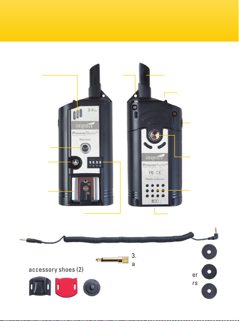
PowerSync16 DC Receiver
Signal conrmation
LED
Female
PC jack
Power
LED
Hotshoe
mount
16-channel selector
Adhesive-backed
accessory sho es (2)
Lanyard
hole
Sync cord
3.5 t o 6.3 mm
adapter plug
Shoe(M)-to-1/4˝
wit h thumbwheel lock
Antenna
Power s witch
1/8˝ mini
(3. 5 mm)
sync jack
1/4˝-20
female
threads
Batter y
bay
AC adap ter input
Spacer
washers
5
Page 6
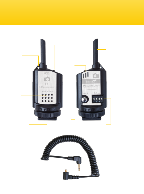
PowerSync16 Transmitter
Lany ard
hole
2.5 mm
sub-mini
jack
Bat tery
bay
Hot shoe
with locking thumbwheel
PC male t o 1/8˝ (2 .5 mm)
mini sync cord
6
Power switch
Signal
conrmation
LED
Tes t
button
Antenna
16-channel
selector
Page 7

Safety WarningsAccessories: Sync Cables
• Do not remove instrument covers during operation.
• Do not operate the PowerSync System in the presence of ammable
gases or fumes. Operation of any electrical instrument in such an
environment creates an extreme safety hazard.
• There are no user-serviceable parts inside the PowerSync Transmitter
and Receiver systems. Do not install substitute parts or perform any
unauthorized modication of either the Transmitter or Receiver.
• PowerSync is an accessory device for ash photography. Do not use
this product in a manner not specied within this documentation.
• Turn your equipment OFF before making electrical connections or
changing batteries.
• Install fresh batteries into the PowerSync System. Make sure to align
batteries with proper polarity. Weak batteries will shorten the distance
of transmission and reception.
• To avoid battery leakage, always remove the batteries when the units
are not in use for more than a month. Do not use or leave the devices
in conditions of extreme heat, severe cold, or high humidity.
7
Page 8

Step 1: Synchronizing Channels Triggering a Remote Camera
For your PowerSync
system to work properly,
both the Transmitter and
Receiver must be set to
use the same channel.
The battery cover on the
Transmitter features a pin
for changing the DIP
switches. With both units
switched OFF, set the DIP
switches to the same
conguration on each.
There are 16 different
possible congurations.
Turn ON both the
Transmitter and Receiver.
The Transmitter has a test
button which you can use
to conrm your set-up.
The Signal Conrmation
LED on the Receiver will
ash to indicate correct
synchronization.
8
With the device switche d OFF, use the
pin on the battery cover to select the
channel.
Both the Transm itter and the Receiver
must be se t to the same channel .
Page 9

There are two methods to connect
the Transmitter to your camera:
Hot-shoe mount
One method is to afx the
Transmitter to the hot shoe of your
camera. Slide the Transmitter into
the hot shoe. The test button should
be at the back, the same side as the
viewnder. Tighten the lock wheel.
Sync cable
The other method is to connect the
supplied sub-mini (2.5mm) phone
jack to the Transmitter, located on
the side of the unit, then plug the
other end of the cord into the PC
connection on the camera.
If your camera doesn’t have a PC
jack, Impact makes sync cables
with other plug types and in a
variety of lengths. See the
Accessories pages toward the back
of this manual or check out the
selection on our website.
Hot-shoe mount
Sync-cable connection
9
Page 10

If using a portable ash unit, you
can attach the ash directly to the
DC Receiver’s hot shoe. With the
1/4˝ female threads on the back of
the DC Receiver, you can then
mount your remote ash on a tripod
or a light stand with an adapter.
You can also use the DC Receiver’s
sync cord to connect directly to a
studio ash. Included with your
kit is a mount that will allow
you to attach the receiver
temporarily to your ash with
an adhesive backing, or you
can use a lanyard. If you are
getting radio interference
from the ash’s electronics,
have the receiver dangle
on a lanyard, keeping the
antenna from being too
close to the ash’s
electronics. Your DC Receiver can now be turned on with
the switch on top of the unit.
10
Page 11

Step 3: Setting Up the Receiver (AC Model)Step 3: Setting Up the Receiver (DC Model)
• Be sure your ash head is turned
OFF. Unplug the power cord from
the wall socket.
• Unplug the AC power cord from
the ash (either the power pack or
mono light) and plug it into the
bottom of the PowerSync AC
Receiver.
• Insert the power cord of the
receiver into the AC power socket
of the ash.
• Then insert the sync cord of the
receiver into the sync socket of
the ash. Once the ash power is
turned ON, the PowerSync AC
Receiver will be turned on
automatically.
The AC version o f the PowerSync
comes complete with 1/4˝ and 1/8˝
(phono pl ug or miniplug) sync
inputs . For other sync opt ions,
see the Accessories page tow ards
the back of th is manual.
11
Page 12

Step 4: Mounting the Receiver Step 2: Setting Up the Transmitter
Shoe mount 1/4˝-20 mount Lanyard
There are many ways you can
mount your PowerSync Receiver to
your ash unit. Attach an adhesivebacked accessory shoe to your
ash and the shoe-to-1/4˝-20
adapter to your Receiver. Or use the
Receiver’s 1/4˝-20 female threads to
mount the Receiver to a light stand
or mounting arm. You can also
thread a lanyard through the
lanyard hole and hang the Receiver
from a light stand, ash handle, or
anywhere else convenient.
The PowerSync’s effective range depends on the orientation and position of the
Transmitter and Receiver. Reception can be affected by large metal or concrete
objects and by bodies of water. Moving one or both devices a few feet is often
enough to solve a reception problem.
12
If mount ing to a ash unit,
it’s best to place the Receiver
so its antenna clears the top of
the ash an d is in direct sight
of the Transmitter.
Page 13

You can use your PowerSync
System to trigger a remote camera.
The camera must have an electronic
shutter release connection, and you
must have a compatible camera
release cable (see Accessories).
Step 1:
Connect your PowerSync DC
Receiver to the electronic shutter
release connection on your camera
using a compatible camera release
cable.
Step 2:
Make certain that both your
PowerSync DC Receiver and
Transmitter are set to the same
channel and are powered up.
Step 3:
Press the TEST button on your
PowerSync Transmitter to trigger
the remote camera. Pressing the
test button halfway will allow your
camera to focus or will wake your
camera from “sleep mode.”
Remote triggering can be done
with the DC Receiver
1 2 3 4 1 2 3 4
Adjust to the same channel
13
Page 14

Your PowerSync Radio Slave system is compatible with a wide variety
of cameras and ash units right out of the box, but you may need an
accessory sync cable for some cameras and/or ash units. Below are
the plug ends commonly in use and the equipment they typically
connect. Verify the plug compatible with your equipment.
PC Standard
Fit s most
professional
cameras.
2.5 m m
Sub-Miniphone
This p lug is typ ically
used on ly on slave
systems.
Household
2-Blade Plug
Fit s most
professional
ashe s with dua l blade
recep tacles, s uch as
Lume dyne, No rman,
Speed otron and D ynalit e (old).
1/8 ˝ (3.5 mm)
Miniphone
Fit s a wide var iety of
ashe s. This is a v ery
popul ar sync plu g.
1/4˝ Phono Plug
Fit s most Bo wens,
Dyna lite (new ),
Monol ite, Pr ofoto,
Speed otron, e tc.
1-1/2 ˝ long plug ;
1/4˝ t hick.
Hot Shoe
Fit s most cam eras
feat uring a hot s hoe
wit h a large
center contact.
See your Impact dealer for a complete list
of plugs and cable lengths available.
14
Page 15

Accessories: Miscellaneous
To use your PowerSync System to trigger your camera shutter, you’ll
need a Camera Release Cable compatible with your camera. Please see
the included cable compatibility insert card.
9031510
9031500
9031520
9031530
9031540
9031500 Miniphone Female to Elinchrom Adapter
9031510 Miniphone Female to Household Adapter
9031520 AC Power Adapter for PowerSync DC Receiver
9031530 Adhesive-backed Accessory Shoe with Thumbwheel Lock
(replacement)
9031540 Adhesive-backed Accessory Shoe – 2 pack
(replacement)
15
Page 16

1. Turn OFF the Receiver (if it’s a DC Receiver) and verify that the
batteries’ polarity is correct. Turn the Receiver back to the ON position.
2. Make sure the batteries in the Transmitter are fresh. Weak batteries
will reduce the distance over which a transmission can be made.
3. Ensure that both the PowerSync Transmitter and Receiver
are connected properly.
4. Make sure that both the Transmitter and Receiver are set to the
same channel.
5. Verify that the ash lighting equipment in use is operating properly
when not connected to the PowerSync Slave System. If triggering a
ash that uses a household-style sync terminal, make certain that the
plug is oriented correctly.
6. Verify that the ash lighting equipment has a sync voltage that is
compatible with the PowerSync Slave System.
Note: The PowerSync Radio Slave System has been rigorously tested with
numerous ash manufacturers and has proven to work in most instances.
There may be some exceptions.
7. Ensure that all cables attached to both the ash and PowerSync
Slave System are fully intact and are not frayed or torn.
8. Check for a stuck test button on all units, including the ash units.
9. Sync speed and working distance are affected by radio reections
and obstructions. Avoid having a large hill, concrete, metal or water
obstructions between the Transmitter and Receiver. Reposition the
units so they are not blocked by these objects. Often moving the
Transmitter and Receiver a couple of feet will solve the problem.
16
Page 17

10M 25M 50M 75M 100M 10Y 25Y 50Y 75Y 10 0Y
Frequency: 2.4 GHz
Channels: 16 digitally-coded channels
Opera ting Range: ~590 fee t (~180 meter s) indoors
+20 0 feet (+6 0 meters) outdoors
Sync Speed: 1/2 50 second maximu m
Trigger Speed: 8 frames/second max imum
Sync Jacks: Transmi tter – 2. 5 mm sub-mi ni female
DC Receiver – 1/8˝ m ini (3.5 mm) female
PC female
hot shoe female
AC Receiver – 1/8˝ m ini (3.5 mm) female
Transmi tter Trigger: 3 V DC
Bat teries: Transmitt er – 1 × CR2450
DC Receiver – 2 × A A 1.5 V
Dimensions: Transmitter – 1.2 × 1 × 3.2˝
(31 × 26 × 8 0 mm)
DC Receiver – 1.7 × 1 × 4.3˝
(43 × 25 × 110 m m)
AC Receiver – 1.7˝ × 1 × 4.3˝
(43 × 25 × 110 m m)
17
Page 18

One-Year Limited Warranty
Backward Compatibility
The PowerSync 16-80 is backward compatible with the PowerSync 16
Radio Slave System.
PowerSync 16 Transmitter to PowerSync 16-80 as Receiver:
The PowerSync 16 transmitter can be used to trigger the PowerSync
16-80. Set your PowerSync 16-80 to Receiver (Rx) or
Transmitter/Receiver (Tx/Rx) mode using the M button to accept a
signal from the PowerSync 16 transmitter. Ensure the channel on both
devices is identical. See chart below.
PowerSync 16-80 Transmitter to PowerSync 16 as Receiver:
The PowerSync 16-80 can be used to trigger the PowerSync 16
receiver. Set your PowerSync 16-80 to Transmitter (Tx) or
Transmitter/Receiver (Tx/Rx) mode using the M button to send a signal.
Ensure the channel on both devices is identical. See chart below.
For channel selection, the PowerSync 16 system relies on manual
channel selector switches. Despite the PowerSync 16-80’s digital
interface, channels on the two devices can be synchronized using the
chart below as a guide
Note: When using the PowerSync 16 – only 16 channels are available.
The PowerSync 16-80’s backward compatibility with the PowerSync 16
system will only work if No Group is selected on the PowerSync 16-80.
18
Page 19

10M 25M 50M 75M 100M 10Y 25Y 50Y 75Y 10 0Y
One-Year Limited Warranty
This IMPACT product is warranted to the original purchaser to be free
from defects in materials and workmanship under normal consumer use
for a period of one (1) year from the original purchase date or thirty (30)
days after replacement, whichever occurs later. The warranty provider’s
responsibility with respect to this limited warranty shall be limited solely to
repair or replacement, at the provider’s discretion, of any product that fails
during normal use of this product in its intended manner and in its intended
environment. Inoperability of the product or part(s) shall be determined by
the warranty provider. If the product has been discontinued, the warranty
provider reserves the right to replace it with a model of equivalent quality and
function.
This warranty does not cover damage or defect caused by misuse, neglect,
accident, alteration, abuse, improper installation or maintenance. EXCEPT
AS PROVIDED HEREIN, THE WARRANTY PROVIDER MAKES NEITHER ANY
EXPRESS WARRANTIES NOR ANY IMPLIED WARRANTIES, INCLUDING
BUT NOT LIMITED TO ANY IMPLIED WARRANTY OF MERCHANTABILITY
OR FITNESS FOR A PARTICULAR PURPOSE. This warranty provides you with
specic legal rights, and you may also have additional rights that vary from
state to state.
To obtain warranty coverage, contact the Impact Customer Service
Department to obtain a return merchandise authorization (“RMA”) number,
and return the defective product to Impact along with the RMA number and
proof of purchase. Shipment of the defective product is at the purchaser’s
own risk and expense.
For more information or to arrange service,
visit www.impactstudiolighting.com or call Customer Service at 212-594-2353.
Product warranty provided by the Gradus Group. www.gradusgroup.com
IMPACT is a registered trademark of the Gradus Group.
© 2014 Gradus Group LLC. All Rights Reserved. Made in China.
19
Page 20

GG3
 Loading...