

Page 1

Page 2

Page 3
WARNINGS
READ CAREFULLY BEFORE OPERATION OF THE DEVICE
LEGAL DISCLAIMERS
►
Comply with applicable laws and regulations governing use of metal detectors
while using this detector. Do not use the detector without authorization in protected or
archeological sites. Do not use this detector around unexploded ordnance or in restricted
military zones without authorization. Notify appropriate authorities with details of any
historical or culturally significant artifacts you find.
WARNINGS
►
IMPACT is a state-of-the-art electronic device. Do not assemble or operate the device
before reading the user manual.
►
Do not store the device and search coil under extremely low or high temperatures for
extended periods. (Storage Temperature: - 20°C to 60°C / - 4°F to 140°F)
►
Do not immerse the device or its accessories (except for the search coil) in water. Do not
expose equipment to excessively humid environments.
►
Protect the detector against impacts during normal use. For shipping, carefully place
detector in original carton and secure with shock resistant packaging.
►
IMPACT metal detector may only be disassembled and repaired by Nokta Authorized
Service Centers. Unauthorized disassembly/intrusion into the metal detector control
housing for any reason voids the warranty.
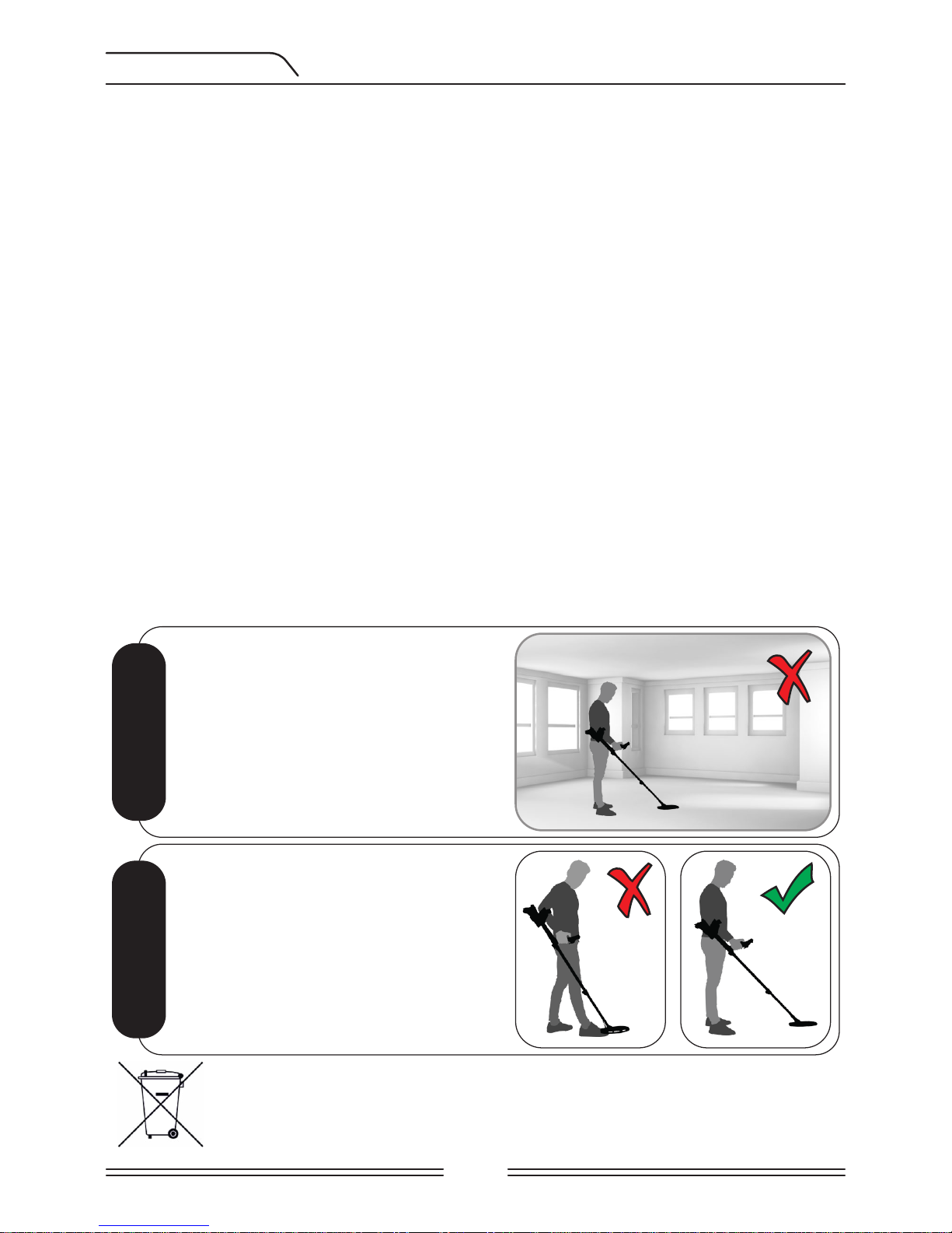
IMPORTANT
IMPORTANT
Do not use the device indoors. The device
may constantly give target signals indoors
where there are many metals present. Use
the device outdoors, in open fields.
Do not let another detector or an electromagnetic device come in close proximity
(10m (30ft.)) to the device.
Do not carry any metal objects while using
the device. Keep the device away from your
shoes while walking. The device may detect
the metals on you or inside your shoes as
targets.
For Consumers within the European Union: Do not dispose
of this equipment in general household waste. The crossed
wheeled bin symbol on this equipment indicates this unit
should not be disposed of in general household waste, but
recycled in compliance with local government regulations
and environmental requirements.
FCC STATEMENT
This device complies with Part 15 of the FCC Rules. Operation is subject
to the following two conditions: (1) this device may not cause harmful
interference, and (2) this device must accept any interference received,
including interference that may cause undesired operation.
Page 4

TABLE OF CONTENTS
ASSEMBLY.......................................................................................................................................................
INTRODUCTION TO THE DEVICE.................................................................................
BATTERY INFORMATION..........................................................................................................
DISPLAY.............................................................................................................................................................
CORRECT USE...........................................................................................................................................
QUICK GUIDE............................................................................................................................................
GROUND BALANCE..............................................................................................................
TARGET ID.........................................................................................................................................
SEARCH MODES (MODE)..........................................................................................
SETTINGS...........................................................................................................................................
BASIC SETTINGS.........................................................................................................
EXPERT SETTINGS...................................................................................................
PINPOINT.....................................................................................................................................................
TARGET DEPTH...................................................................................................................................
LARGE OR SHALLOW TARGETS.................................................................................
FALSE SIGNALS AND REASONS................................................................................
MAGNETIC MINERALIZATION INDICATOR....................................
ROCKS AND SEARCHING IN ROCKY TERRAINS.....................
TRACKING AND EFFECTS OF ROCKS...............................................................
METALS UNDER ROCKS..............................................................................................
SEARCHING IN SHALLOW WATER AND BEACH...............................
MESSAGES.................................................................................................................................................
SOFTWARE UPDATE...................................................................................................................
TECHNICAL SPECIFICATIONS.......................................................................................
1
2
3
4
5
6
7-10
10-11
12-15
16-24
16-20
21-24
25
26
26
26
26-27
27-28
28
28-29
29
30
30
31
Page 5
1
6
9
5
7
8
2
3
2
4
4
Page 1
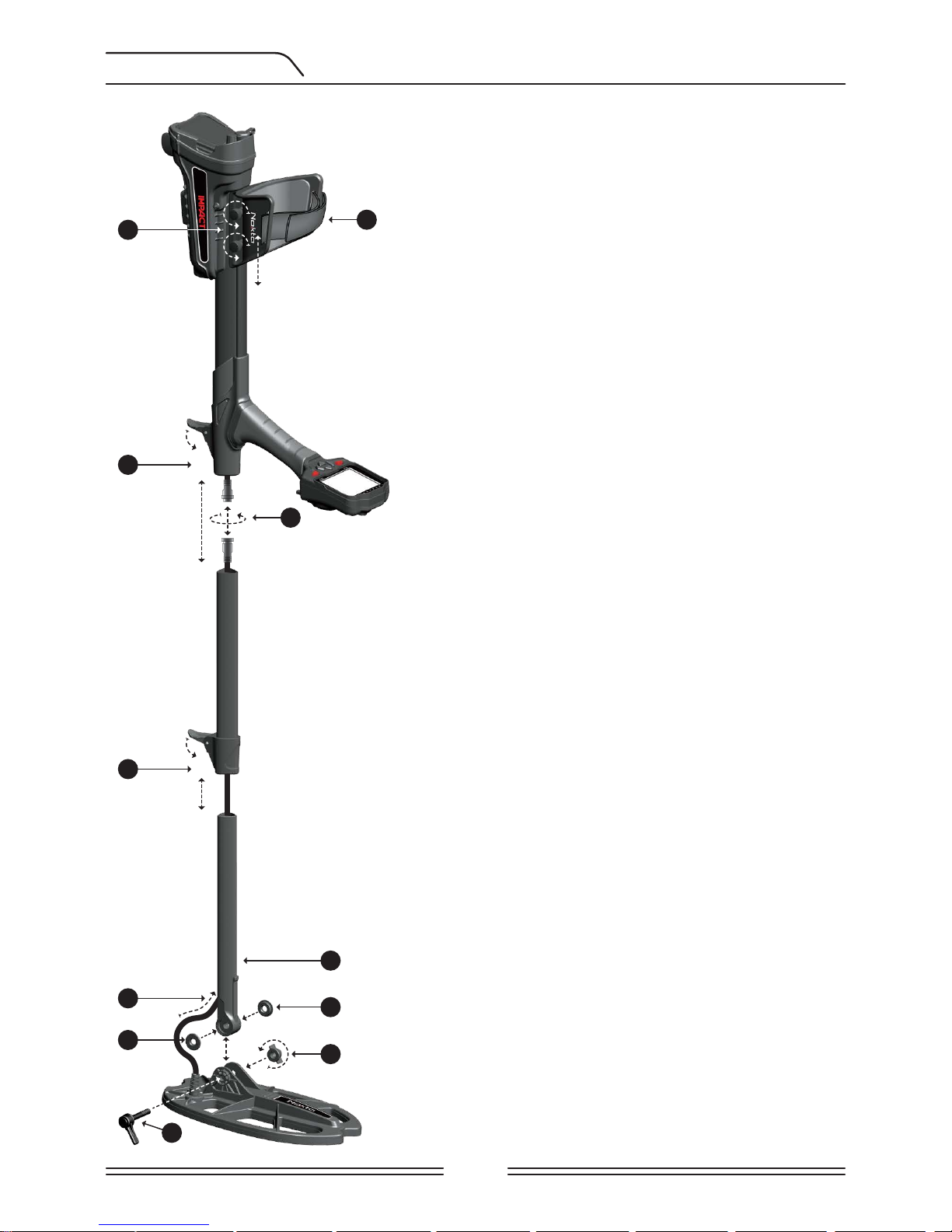
ASSEMBLY
(1) Insert the search coil cable through the hole at
the back of the lower shaft.
(2) Insert the washers on the lower shaft yoke.
(3) Insert the lower shaft yoke between search coil
mount tabs.
(4) Attach the search coil to the lower shaft using
the lever and winged nut without over-tightening.
(5) Fully insert the middle shaft into the lower shaft
and push it until it contacts the stopper. Then,
secure with the lever latch. If the lower shaft is not
inserted fully, the connector at the end of the cable
will not come out from the top of the shaft in the
next step.
(6) Join the two connectors of the system box cable
and coil cable paying attention to the pins, then
tighten. The system box cable is a retractable spiral
and you can pull it in case you cannot join the two
connectors easily.
(7) Join the middle and the upper shafts. Pull the
excess cable out of the hole and push the lever
latch on the upper shaft to secure. To adjust the
shaft length, loosen the lever latch on the middle
shaft, adjust the length to your height and press
the latch to secure.
(8) To adjust the armrest, loosen the bolts. Slide the
armrest up and down to adjust it to your arm and
secure by tightening the bolts.
(9) Adjust the armrest strap to your comfort.
Page 6
Page 2
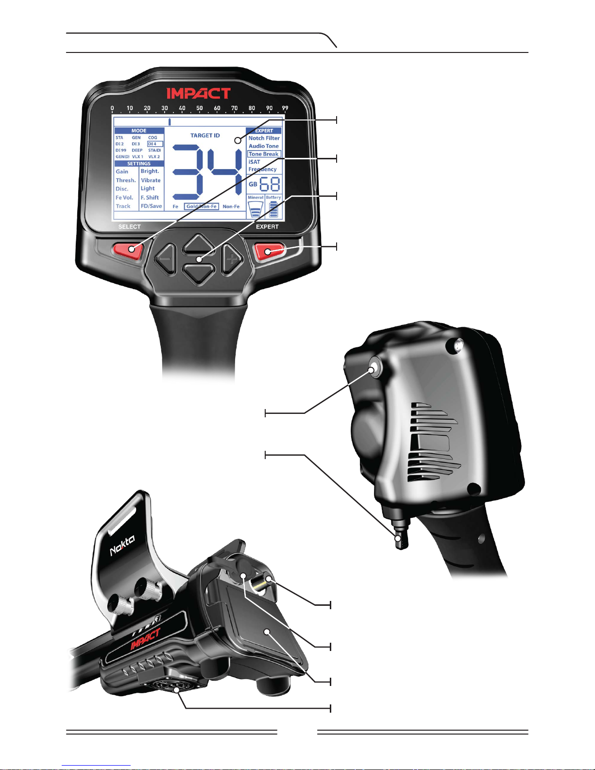
INTRODUCTION TO THE DEVICE
LCD Display
SELECT button to access the
basic settings
Keypad for navigation among
menu options and changing the
device settings
EXPERT button to access the
expert settings
LED flashlight
On / Off and volume / overload
volume adjustment button
Headphone jack
Battery compartment cover
Speaker
Ground balance and pinpoint trigger
Page 7
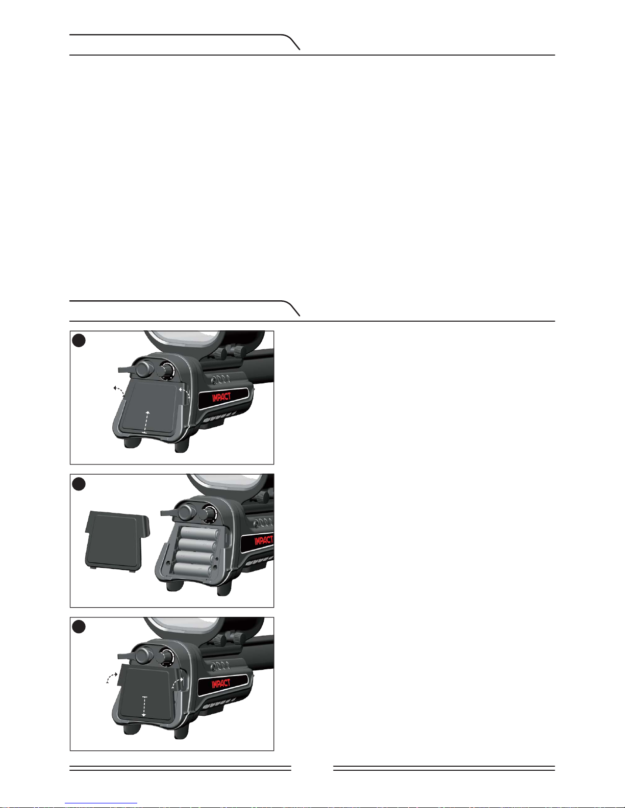
1
Push down on the tabs on both sides and pull the
cover up in the direction of the arrow shown in
the picture.
Install the batteries, making sure to match the
positive and negative ends of the batteries to
the correct contacts.
Place the battery cover in the direction of the
arrow shown in the picture. Push down on the
tabs to get the cover click into its place.
2
3
Page 3
BATTERY INFORMATION
BATTERY INSTALLATION
The device is supplied with 4 AA Alkaline batteries.
The device can be used for approximately 9-17 hours based on the operating frequency
chosen. Battery life will be less in 5kHz compared to other frequencies. Other factors such
as LED flashlight usage and usage of speaker or wired/wireless headphones will also affect
battery life.
AA Alkaline batteries are recommended for the best performance. Good quality Ni-MH
rechargeable batteries can be used, instead. Rechargeable batteries with high mAh (capacity)
ratings offer extended operating times versus batteries with lower rating. Do not mix alkaline
and rechargeable batteries.
Low Battery Level
Battery icon on the display shows the battery life status. When the charge decreases, the
bars inside the battery icon decrease, too. "Lo" message appears on the display when the
batteries are depleted.
Page 8
Page 4
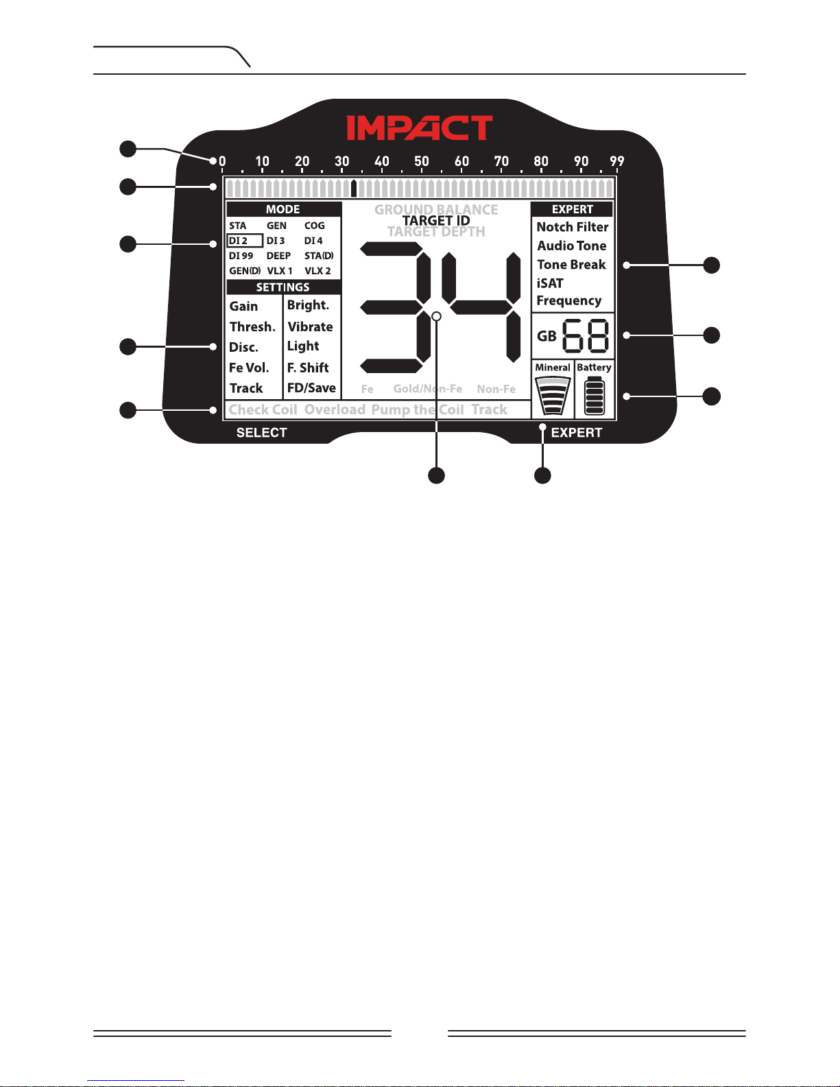
DISPLAY
2
3
4
8
9
10
6 7
1
5
(1) Target ID scale.
(2) Cursor showing the ID of the detected target on the ID scale. It also indicates the IDs
filtered by Disc. and Notch Filter settings as well as the tone breakpoints. In the Static
modes, it indicates the signal strength.
(3) Search Modes.
(4) Basic Settings.
(5) Section which shows the warning messages.
(6) Section which shows the Target ID upon target detection, the ground balance whole
number value during ground balancing and the estimated target depth in the pinpoint
mode. In addition, the numeric value of any setting selected from the menu is displayed
in this field.
(7) Magnetic mineralization indicator.
(8) Expert Settings.
(9) Section which shows the fine tuning value during ground balance adjustment and
current ground balance value during search.
(10) Battery level indicator.
Page 9
Page 5
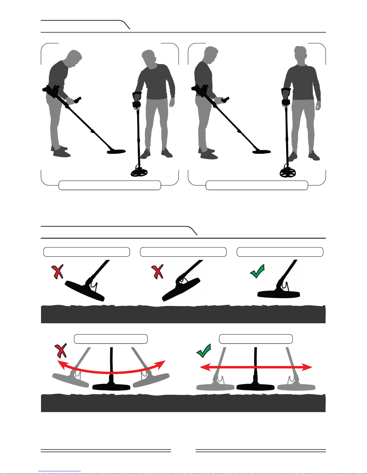
CORRECT USE
CORRECT WAY OF SWEEPING
Shaft height is wrong Shaft height is correct
It s very mportant to adjust the shaft to your
heght correctly to be able to search wthout
dscomfort and fatgue.
Adjust the heght of the shaft so that you are
standng n an uprght poston, your arm s
relaxed and the search col s approxmately
5cm (~2'') above the ground.
It s mportant to keep the search col
parallel to the ground n order to get
accurate results.
The search col must be parallel to the
ground at all tmes.
Wrong search coil angle Wrong search coil angle Correct search coil angle
Incorrect way of sweeping Correct way of sweeping
Page 10

Page 6
QUICK GUIDE
1) Assemble the device as per the instructions on page 1.
2) Insert the batteries by paying attention to +/- polarity.
3) Rotate the on/off switch located behind the device clockwise to turn on the device. This
switch also adjusts the volume of the device as well as the overload volume.
4) When the device is turned on, it will start in the DI2 mode and 14kHz operating frequency.
You can change the mode and/or the frequency based on ground conditions. For instance, if
you are detecting on wet beach sand, you may want to select the COG mode and a different
frequency. You can find more details on search modes and frequencies further in this manual.
5) To ground balance, push and hold the trigger forward and pump the search coil up and
down to 3cm (1.2'') above the ground until a “beep” sound is heard.
6) You can increase the Gain if needed. Increasing the gain will offer you greater depth.
However, if the surroundings or the ground cause excessive noise in the device, you need
to lower the gain setting.
7) Testing the device with various metals would be helpful for getting familiar with the
sounds produced by the device.
8) Based on the IDs of the metals you don't want to detect, you can adjust the Disc. setting
and ignore those metals. For instance, if you don’t want to detect ferrous metals with 00-05
ID in the DI2 mode, you can set the Disc. to 5.
9) If you are detecting in a very trashy area and the device is getting too many iron signals,
instead of Disc. you can use the Fe Vol. to lower or completely turn off the iron audio. This
will provide more depth.
10) You can filter out certain Target IDs using the Notch Filter and enable the device to ignore
these metals during searching or to provide an iron audio for them.
11) If you wish, you can adjust the tone break points of the device with the Tone Break
feature and change the frequency of the tones using the Audio Tone setting.
12) You can now start searching.
13) Since your device operates with the motion principle, swing the search coil right and
left maintaining 5cm (2") distance above the ground. If the search coil does not move, the
device will not provide any audio responses even if the coil is over a metal target (except
for the STATIC modes).
14) When a target is detected, the ID of the target will be displayed on the screen and the cursor
will indicate its position on the ID scale. (If you wish, you can adjust the ID Depth Level of the
device). The device will also produce an audio response according to the search mode selected.
15) Upon target detection, you can pinpoint the exact location of the target by pulling
and holding the trigger back. The audio volume will increase and the audio pitch will also
increase as you approach the target.
Page 11
Page 7
GROUND BALANCE
Ground balance can be performed in three ways with the IMPACT: Automatic, Manual and
Tracking (Track).
If the trigger is pushed forward while performing automatic or manual ground balance,
the device will switch to the General Search (GEN) mode automatically on the background
without any indication to the user, regardless of the selected search mode.
Upon completion of ground balance, current ground balance value is shown in the Ground
Balance (GB) box on the right side of the display.
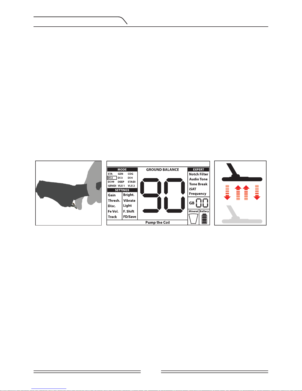
Automatic Ground Balance
Automatic ground balance is performed as follows in all search modes:
1) Find a spot where there is no metal.
2) Push the ground balance trigger forward (GROUND BALANCE value and “Pump the Coil”
warning message will be shown on display) and start pumping the search coil up and down
from about 15-20 cm (~6''- 8'') above the ground down to 3 cm (~1'') off the ground with
smooth movements and keeping it parallel to the ground.
3) Continue until a beep, indicating the completion of ground balance, is heard. Based on
ground conditions, it usually takes about 2-4 pumps for the ground balance to be completed.
4) Upon completion of the ground balance, ground balance value is shown on the display
(GB). The device continues to ground balance and produce a beep sound as long as you keep
the trigger pushed forward and pump the coil. In order to ensure that the ground balance is
proper, ground balance at least 2-3 times and check the ground balance values on the display.
In general, the difference between the values shall not be higher than 1-2 numbers.
5) If you cannot ground balance, in other words, if no beep sound is produced, it means that
either the ground is too conductive or not mineralized or there is a target right below the
search coil. In such a case, retry ground balance at a different spot. If you still cannot ground
balance, read the section titled “Important Details Concerning Ground Balance”.
When the ground balance trigger is released, the device continues to operate in the GEN
mode for a short period of time and the ground balance value stays on display. This makes
it possible to manually fine tune the automatic ground balance value. Refer to the following
“Manual Ground Balance” section for further information regarding this feature. If this is not
desired, pull and release the trigger once to return to the main screen.
Page 12
Page 8
NOTE: If the iSAT value is set high, the device may not auto ground balance. In such a case,
lower the iSAT value first. After ground balancing, set the iSAT back to its original position.
Manual Ground Balance
Allows you to manually modify the ground balance value. It is not preferred mostly because
it takes time. However, it is the preferred option in cases where a successful ground balance
cannot be performed using other methods or minor corrections are required to the
automatic balance.
IMPACT is designed to allow for automatic ground balancing conveniently on any type of
ground. Therefore, it is recommended to perform automatic ground balance upon start up.
However, the ground may not be suitable for automatic ground balancing in some cases
and the device cannot ground balance on such grounds (Except for the COG mode). For
instance, wet beach sand, soils containing alkali or salty water, trashy sites, ploughed fields,
highly mineralized grounds and grounds with very low mineralization are not suitable for
automatic ground balance. In such terrains, you can auto ground balance in the COG mode
and then switch to other modes or try manual ground balancing. However, manual ground
balance requires a skill which develops over time through practice.
To perform manual ground balance:
1) Find a clear spot without metals and switch the device to the GEN mode.
2) You need to listen to the sounds coming from the ground in order to perform manual
ground balance. Pump the search coil up and down from about 15-20 cm (~6''- 8'') above
the ground down to 3 cm (~1'') off the ground with smooth movements and keeping it
parallel to the ground.
If the sound gets higher when lifting off the search coil above the ground, the ground
balance value is too low, in other words, the effect from the ground is negative and the
ground balance value needs to be increased by using the ( + ) button. On the other hand,
if the sound gets higher when lowering the search coil to the ground, the ground balance
value is too high, in other words, the effect from the ground is positive and the ground
balance value needs to decreased by using the ( - ) button.
3) Push the ground balance trigger forward once and release it. The ground balance value
will be shown on the display and remain there for a moment. You can return to the ground
balance screen by pushing the ground balance trigger forward if the screen switches.
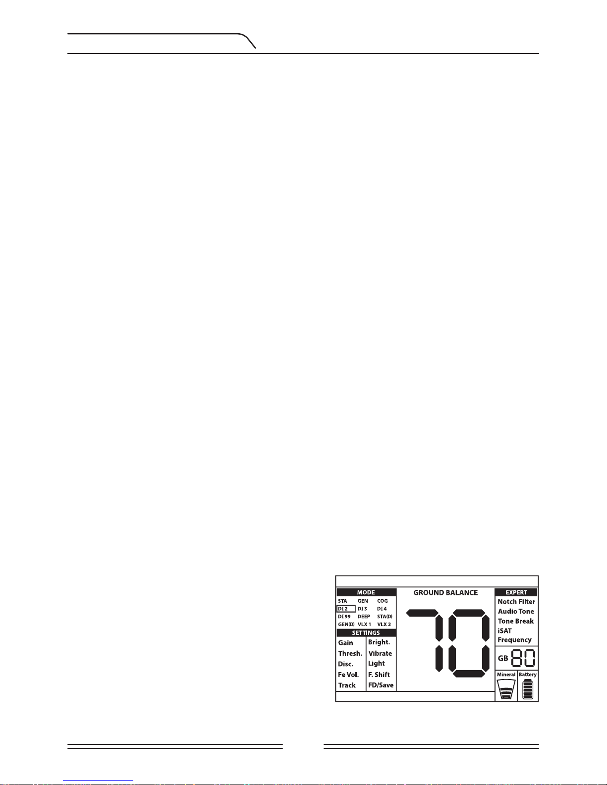
Manual ground balance functions within the range
of 0-99. However, each value covers 5 steps used
for fine tuning within itself and these steps are
indicated as multiples of 20 in the Ground Balance
window (GB). For example, ground balance value
shown on the side is 70.80.
Press ( + ) or ( - ) to increase or decrease the ground
balance value, respectively. If the key is pressed
once at a time, the values count one by one and if it is held down, the values will change
quickly.
GROUND BALANCE
Page 13

Page 9
4) Repeat the above procedure until the sound heard from the ground is eliminated.
The sound may not be eliminated completely in some areas. In these cases, listen to the
sounds produced when moving the search coil towards and away from the ground to check
if the ground balance is correct. If there is no difference between the two sounds then the
ground balance is set properly.
The device will return to the main screen automatically after a short period of time upon
completion of ground balance. To return to the main screen instantly, just pull and release
the trigger once.
IMPORTANT! Experienced detectorists adjust the ground balance setting to a slightly positive response (weak but audible sound is produced when moving the search coil closer to
ground). This method may produce favorable results for experienced users in certain fields
where small targets are searched for.
Ground Tracking (Track)
In this option, the user does not need to make any adjustments. Tracking feature is activated
from the menu by switching it to 01 position. The word ''Track'' is displayed at the bottom of
the screen. The device updates the ground balance automatically as long as the search coil is
swung over the ground and shows the ground balance value in the GB window. It does not
provide any feedback to the user (like the beep sound in automatic ground balance).
While tracking is active, the device can initially produce a loud signal when it detects a
different ground structure (for instance a mineral rock) or a target. In this case, swing the
search coil over the spot where the device produces the signal . If the sound remains the
same and the device shows an ID, it is possibly a target. If the sound attenuates too much
or is lost after a few swings, it means that the device has produced a signal for the different
ground structure or a stone.
NOTE: It is recommended that you use tracking in the General Search modes (GEN and GEN
(D)) and not in the discrimination or static modes.
Tracking is suitable for use in areas where different soil structures are present within the
same land or in fields where mineralized rocks are scattered widely apart. If you use ground
tracking in areas where hot rocks are intensely present, the device may not be able to eliminate these highly mineralized rocks or you may miss the smaller or deeper metals.
IMPORTANT! Ensure that tracking is off during air tests. Otherwise, the device will attempt
to perform ground balance on the target and the depth will be reduced.
Ground Balance Value
Ground balance value provides information about the ground you are searching on. Some
typical ground types are as follows:
0-25 Wet salt water or wet alkali soils
25-50 Wet salt water and wet alkali soils covered with dry layers
50-70 Regular, low-quality soils
70-90 Highly magnetic soils, magnetite or maghemite and similar highly mineralized soils,
black sand.
GROUND BALANCE
Page 14

Page 10
Important Details Concerning Ground Balance
1) Upon start up, the ground balance value is set to 90. The device can perform ground
balance automatically within the range of 20-90 in all modes and 00-90 in the COG mode.
2) If the ground mineralization is too low, automatic ground balance may fail to work in
other modes except for the COG mode. In such a case, you can auto ground balance in the
COG mode and then switch to other modes or try manual ground balancing.
3) You can test the accuracy of the ground balance with the pinpoint mode. After ground
balancing, if you receive no sound or a weak one when you move the search coil closer to
the ground in the pinpoint mode, then the ground balance is successful. If the sound gets
louder when you move the search coil closer to the ground, then the ground balance is not
successful. In this case, simply change your location. If ground balance is not possible despite
these efforts, you should continue your search without performing ground balance.
You cannot search in the General Search and Static modes without ground balancing. You need
to use one of the discrimination modes and increase the Disc. value until the noise is eliminated.
4) Once the ground balance is set, it will remain satisfactory for a long time in most areas.
However, if you encounter an excavated, backfilled or geologically composite soil structure,
a ground balance should be performed again to adapt to the varying soil structure. In
addition, re-ground balancing is recommended if you change the operating frequency of
the device (5kHz/14kHz/20kHz) in certain ground conditions.
5) When using the optional large coil, pump the coil more slowly and do not keep it very
close to the ground.
6) In some cases where the iSAT value is set high, the device may not be able to ground
balance automatically. In such a case, first lower the iSAT and after ground balancing switch
it back to its previous position.
TARGET ID is the number produced by the metal detector based on the conductivity of the
metals and gives an idea to the user about what the target may be. Target ID is shown with
two digits on the display and ranges between 00-99.
NOTE: Keep in mind, large targets will ID higher than expected, even though they may be
of lower conductance.
In some cases, the device may produce multiple IDs for the same target. In other words, the
IDs may be jumpy. This may result from several factors. Target orientation, depth, purity of
the metal, corrosion, mineralization level of the soil etc. Even the direction of the search coil
swing may cause the device to generate multiple IDs.
In some cases, the device may fail to provide any ID. The device needs to receive a strong and
a clear signal from the target in order to provide an ID. Therefore, it may not be able to provide
an ID for targets at fringe depths or smaller targets even if the device detects them.
TARGET ID
GROUND BALANCE
Page 15

Page 11
Keep in mind that target IDs are “probable”, in other words, estimated values and it would
not be possible to know the properties of a buried object exactly until it is dug out.
IDs of non-ferrous metals such as copper, silver, aluminum and lead are high. Target ID range
of gold is wide and may fall within the same range of metal wastes such as iron, foil, screw
caps, and pull tabs. Therefore, if you are looking for gold targets, digging out some trash
metals is expected.
IMPACT utilizes 2 different ID scales according to the search modes. In DI2, DI3, DI4, DI99 and
COG modes, the ferrous range is 00-15 at factory defaults. In GEN, GEN (D), STA, STA (D), DEEP,
VLX1 and VLX2 modes, the ferrous range is 00-40. In addition, when the operating frequency
is changed, the Target ID will change as well. This represents the ''Standard'' ID scaling of the
device.
IMPORTANT! At start up, IMPACT will utilize the ''Normalized'' ID scale and not the
Standard ID scale. In other words, the IDs will not change upon frequency change and
the device will generate the 14kHz IDs in each frequency. However, based on ground
conditions IDs may vary for certain metals.
If you prefer to see the different IDs produced by each frequency, you need use the
''Standard'' ID scale. To switch to the standard IDs, pull the trigger and push the (+) button
at the same time. Letters ''Sd'' will appear on the screen. If you wish to revert back to the
normalized IDs, repeat the same process and letters ''no'' will appear on the screen.
Tables outlining the search modes and ID ranges as well as the probable IDs for each
frequency are placed at the back of this manual. You can easily detach the pages and
carry them with you during your searches.
Coins searched throughout the world are made of different metals and in different sizes in
different geographical locations and historical eras. Therefore, in order to learn the Target
IDs of the coins in a specific region, it is suggested to perform a test with the samples of such
coins, if possible.
It may take some time and experience to make best use of the Target ID feature in your
search area. Different brands and models of detectors produce different target ID numbers.
The numbers vary even more depending on target depth, ground mineralization, and
adjacent metals. But after some practice, you will quickly become comfortable with the
meanings of the IMPACT's Target IDs.
Target ID Depth
This setting is not present in the menu.
Adjusts the depth level that the device displays an ID for a detected target. It consists of 3
levels: Hi (High), In (Intermediate), Lo (Low). Factory default is set to ''In''.
The lower the ID depth level is, the higher the ID accuracy and vice versa. At the high level,
the IDs may become jumpy.
To change the ID depth level, pull the trigger and press the up button simultaneously. Each
time you press the up button, the ID depth level will change.
TARGET ID
Page 16

Page 12
SEARCH MODES
IMPACT has 12 search modes (2 static, 2 all metal and 8 discrimination) designed for different
terrains and targets. You can navigate between the modes easily by using the direction
buttons. The selected mode name will be framed on screen.
Tables outlining the search modes, recommended areas of usage and settings used in
each mode are placed at the back of this manual. You can easily detach the pages and
carry them with you during your searches.
Static Mode (STA)
This is a non-motion mode. In other words, the device will generate an audio response
when you hold the coil stationary without swinging over the target. The audio response
increases in volume as the coil approaches the target. This mode is recommended for larger
and deeper metals.
In the STA mode, the device will generate the same audio tone for all metals and it will
display the target ID on screen. At the same time, the ID scale will fill up to the right in
proportion to the signal strength.
Target ID range is 00-99. 00-40 are ferrous and 41-99 are non-ferrous metals. You can
discriminate out all IDs below a certain ID by using the Disc. setting and simply avoid
these metals in the field.
When the device detects a discriminated metal, it will not produce an audio response or an
ID. However, the ID scale will fill up to the right in proportion to the signal strength.
The threshold in this mode is internal and cannot be adjusted by the user. Changes in the
ground and temperature may lead to drifts in the threshold. Threshold drifts will be reflected
in the ID scale either in the positive way (right side) or the negative way (left side). The device
may emit an audible response in the positive drifts but not in the negative ones. When the
threshold drifts, pull the trigger once to retune the detector. Retuning periodically while
searching in this mode is recommended.
IMPORTANT! For a more stable operation, try keeping the coil consistently at the same
height above the ground where you retuned the detector.
IMPORTANT! If you retune the detector over a target, the threshold will drift to the negative
side and the device will no longer detect the target until the detector is retuned. In addition,
the depth of the detector will also decrease.
If the drifts are substantial and retuning does not improve the situation, increase the iSAT
setting in the Expert Settings to a level where the drifts are eliminated (for detailed informa-
tion on iSAT please refer to page 24). As the iSAT is increased, the device may detect weaker
signals but will not be able to detect the targets anymore if you hold the coil stationary or
sweep back and forth over the target. If the drifts still continue frequently, drop the gain to
39, decrease the iSAT and re-ground balance.
Static Delta Mode (STA (D))
In principle, it works the same as the static mode. The difference is that the static delta mode
Page 17

Page 13
will generate the same tone for ferrous and non-ferrous targets at fringe depths but it will
discriminate the shallow ferrous targets by emitting a low iron tone. Also, Disc. setting is not
available in this mode.
Please refer to Table 2 at the end of the manual for different settings used in STA and STA (D)
modes.
General Search (GEN)
Different than the other modes, this mode features a threshold tone which is continuously
heard in the background.
General Search (GEN) mode is used in 2 different ways in the IMPACT: 1) with the Disc. setting
disabled at 0 2) with Disc. enabled (non-zero). When the device is first turned on, Disc. setting
will be off. When the Disc. is set at 0, the device does not discriminate targets and detects
all targets (metals, mineralized rocks etc.). ID of the detected target is shown on the display
(except for negative hot rocks) and the same audio tone is provided for all targets. The audio
tone increases in pitch as the coil approaches the target. This is the typical All Metal mode
found in most detectors.
When using the Disc. Setting in this mode, the device will emit a low ferrous tone for all
targets below the Disc. Setting, and a higher tone for all targets above the Disc. setting
which changes in pitch as the coil approaches the target. Let's say you set the Disc. to 20.
The device will generate a low iron tone for all metals with 0-20 ID and a higher tone for
all targets with 21-99 ID. Upon target detection, the threshold will momentarily go silent
and only the target audio response will be heard. The duration of the threshold's silence is
directly related to the level of the iSAT.
Gain, threshold and iSAT settings in this mode are optimized to provide the best performance on different terrains. You can modify these settings based on ground conditions.
We recommend using the GEN mode when discrimination is not important and not using
it in heavy trash areas or areas containing many hot rocks.
Audio Boost in the General Search Mode
This feature is not included in the settings on screen. Boosts the sound of weak signals
received from small or deep targets making it easier for you to detect those uncertain
targets. It is recommended that audio boost should be used on a temporary or as-needed
basis because it will not only boost the target signal audio but it will also boost the volume
of ground noise and false signals along with the threshold hum.
Audio Boost consists of 5 levels (b1-b5). At start up, the Audio Boost level is set to low (b1). To
increase the Audio Boost level, pull the trigger and press the minus (-) button simultaneously.
Audio Boost will only work in the GEN mode.
General Search Delta (GEN (D))
In principle, it works the same as GEN mode. The difference is that the Gen (D) mode will
generate the same tone for ferrous and non-ferrous targets at fringe depths but it will
discriminate the shallow ferrous targets by emitting a low iron tone.
SEARCH MODES
Page 18

Page 14
Please refer to Table 2 at the end of the manual for different settings used in GEN and GEN
(D) modes.
2-Tone Discrimination (DI2)
Recommended especially for relic hunting. It produces good results particularly on clean
sites which do not contain waste metal. More depth can be obtained on sites which are
rocky or those that contain waste metals by using the Disc. and Notch Filter and swinging
the search coil more slowly (one right/left pass per approximately 1 second). Disc. is set to
03 as a default value. You can modify this value according to the ID of the targets you don’t
want to detect.
In this mode, the device produces a low tone for ferrous targets with IDs between 0-15.
For targets with IDs 16-99, it produces a higher tone which increases in pitch as the coil
approaches the target. By using the Tone Break feature, you can adjust the break points of
the target response tones on the Target ID range.
3-Tone Discrimination (DI3)
This is the 3-tone discrimination mode designed for coin hunting especially in trashy sites
such as parks. In this mode, the device produces a low tone for ferrous targets with 0-15 IDs, a
medium tone for gold and non-ferrous metals with IDs 16-66 and a high tone for non-ferrous
metals with IDs 67-99 such as silver, brass and copper. By using the Tone Break feature, you
can adjust the break points of the target response tones on the Target ID range.
4-Tone Discrimination (DI4)
4-tone discrimination mode designed for coin hunting in low-medium mineralization. Due
to its high gain and depth, this mode is a bit noisier than the other modes. Noise will be
more in the air versus in the ground. Take this fact into consideration when adjusting the
gain level.
In this mode, the device produces a low tone for ferrous targets with 0-15 IDs, a medium tone
for gold and non-ferrous metals with IDs 16-30, a medium-high tone for metals with 31-66
IDs, and a high tone for non-ferrous metals with IDs 67-99. By using the Tone Break feature,
you can adjust the break points of the target response tones on the Target ID range.
99-Tone Discrimination (DI99)
Multi-tone discrimination mode designed for coin hunting in various mineralization. In this
mode, the device produces a low tone for ferrous targets with 0-15 IDs. For targets with IDs
greater than 15, the device will produce a different tone for each ID. The tone will be higher
in pitch as the conductivity of the metal increases and vice versa.
Conductive Ground (COG)
This is a special mode of the IMPACT developed for conductive grounds (salty wet sand
beach, grounds with alkali soil etc.). The feature of this mode presents the ability to ignore
iron and similar targets in this group and to be able to perform ground balance on any type
of ground. While the device performs ground balance in the range of 20-90 automatically
in the other discrimination modes, the device ground balances in the range of 0-90 in this
mode. This enables easier ground balancing on conductive grounds where normally ground
SEARCH MODES
Page 19

Page 15
balance cannot be performed at all or performed with difficulty.
In this mode, the device produces a low tone for ferrous targets with IDs between 0-15.
For targets with IDs 16-99, it produces a higher tone which increases in pitch as the coil
approaches the target. By using the Tone Break feature, you can adjust the break points of
the target response tones on the Target ID range.
Different than the other modes, the Disc. is set to 15 as a default value in this mode in order
to ignore ferrous metals or ground noise.
Salt water and alkali grounds are significantly conductive due to high ionization and cause
effects similar to that of iron in detectors. These effects may make it impossible to search
for metals with a standard detector. Existence of an iron elimination feature in a detector
can improve the situation but may not be sufficient.
IMPACT's COG mode eliminates such effects and ground noise. Aspects to be taken into
consideration while searching on conductive grounds are explained in more detail in the
section titled Searching in Shallow Water and Beach (page 29).
Deep Mode (DEEP)
Recommended especially for relic hunting, this mode is the deepest mode of the device.
Therefore, it may run relatively noisier. Noise will be more in the air versus in the ground. Take
this fact into consideration when adjusting the gain level. While searching in this mode, a
slower swing speed is required.
The discrimination ability of the DEEP mode is relatively less compared to the other modes.
Hence, its performance may vary on trashy sites versus clean ones.
In this mode, the device produces a low tone for ferrous targets with IDs between 0-40. For
gold and non-ferrous targets with IDs 41-99, it produces a higher tone which increases in
pitch as the coil approaches the target. By using the Tone Break feature, you can adjust the
break points of the target response tones on the Target ID range.
VLX1
3-tone discrimination mode designed for users who prefer a lower noise level while detecting.
Ideal for coin hunting on changing grounds and different levels of mineralization. It will
provide weaker responses for fringe depth targets as well as ground and environmental noises.
Therefore, it is suitable for use with Disc. set to 0 and at higher gain levels. If needed, a more
stable operation can be obtained by increasing the Disc. but Disc. will create a greater loss in
depth in this mode compared to others.
VLX2
Resembles the VLX1 in terms of characteristics. However, it is a deeper mode utilizing 4-tones
and it is ideal for both coin and relic hunting in changing ground conditions and all levels of
mineralization.
SEARCH MODES
Page 20

Page 16
SETTINGS
Tables outlining the settings and the modes they are associated with are placed at the
back of this manual. You can easily detach the pages and carry them with you during
your searches.
Basic Settings
Push the SELECT button to access the basic settings. You can navigate the basic settings
with the up and down buttons. The value of the selected setting will be displayed on screen.
You can change the value using the plus (+) and minus (-) buttons. If the up/down and +/buttons are held down, the options and values will change rapidly.
To exit the settings, press the SELECT button or pull the trigger once. Settings will time out
in approximately 8 seconds and the device will revert back to the modes window.
Expert Settings
Push the EXPERT button to access the expert settings. You can navigate the expert settings
with the up and down buttons. The value of the selected setting will be displayed on screen.
You can change the value using the plus (+) and minus (-) buttons. If the up/down and +/buttons are held down, the options and values will change rapidly.
To exit the settings, press the EXPERT button or pull the trigger once. Settings will time out
in approximately 8 seconds and the device will revert back to the modes window.
NOTE: You can go from basic settings to expert settings directly simply by pressing the
EXPERT button. However, you cannot go from expert settings back to basic settings directly.
You will need to go back to the modes window first and then push the SELECT button.
NOTE: Certain settings are mode specific and thus cannot be selected in other modes. For
details, please review Table 3.
BASIC SETTINGS
GAIN
Gain is the depth setting of the device. It is also used to eliminate the ambient electromagnetic signals from the surrounding environment and noise signals transmitted from ground.
NOTE: To obtain maximum depth performance, to eliminate the noise caused by electromagnetic interference, try shifting the frequency first (F. Shift). If this is not sufficient, change
the operating frequency of the device (5kHz/14kHz/20kHz) before lowering the gain.
Gain setting range is 01-99 and pre-defined for each mode. All modes start at default
settings. They can be manually modified when necessary. Gain adjustment applies to the
selected mode; the modified setting does not affect the gain setting of the other modes.
NOTE: If the ground is highly mineralized causing the device to overload, decrease the gain
until the ''Overload'' message disappears from the screen.
Gain in General Search Modes (GEN and GEN (D))
In the GEN modes, gain setting causes an increase or decrease in the popping sounds and
Page 21

Page 17
false signals. Gain setting is a personal preference. However, It is important to set the gain setting to the highest level possible where no major popping sounds are heard to avoid missing
smaller and deeper targets. For example; if the noise level is suitable for searching and is the
same at gain levels 40 and 70, then 70 should be preferred. Using the factory default levels
will be a good starting point until you get familiar and experienced with the device.
Gain in Discrimination Modes:
Since the threshold setting is not available in the discrimination modes, you can increase
the depth of the device or ensure noise-free operation on different grounds only by using
the gain setting.
In order to adjust the gain in the discrimination modes, first ground balance while the gain
is at its default setting. After ground balance is completed, hold the search coil stationary
or swing over the ground at search height. Reduce the gain if the device receives noise. If
not (ensure that the Disc. is also at its default settings when checking this), increase the
gain gradually until there is no popping sound. If the device starts to receive noise during
searching, reduce the gain gradually.
NOTE: IMPACT is a high gain device and some of the search modes will run relatively noisy
(Deep, DI4, VLX2) compared to other modes so as to provide the best depth performance.
However, due to the design characteristics of these modes, the noise will be heard more if
the coil is in free air than sweeping the coil on the ground. Please keep this factor in mind
while adjusting the gain.
Gain in Static Modes:
The factory default for the gain setting is optimized. In situations where you would like to
adjust the gain setting (sudden changes in weather conditions, different ground structures
and environmental noise), first re-ground balance. If there are significant positive or negative
threshold drifts after ground balancing, increase the iSAT setting in the Expert Settings. If the
drifts still continue frequently, drop the gain to 39, decrease the iSAT and re-ground balance.
In situations where the environmental and ground conditions allow, you can obtain more
depth by increasing the gain and lowering the iSAT.
Threshold (Thresh.)
In the General Search Modes (GEN and GEN (D)), search is performed with a continuous
humming sound in the background, also referred to as the threshold sound. The loudness
of this hum directly impacts the detection depth of smaller and deeper targets and it is
adjusted by the threshold (Thresh.) setting. If the threshold is set too high, a weak target
signal may not be heard. On the contrary, if the threshold is too low, you give up the depth
advantage this setting offers. In other words, weak signals of smaller or deeper targets may
be missed. It is recommended for average users to leave this setting at its default value
and for experienced users to adjust to the highest level where they can still hear the weak
target signals.
Threshold level is directly related to the Gain and iSAT settings. Please be sure to read the
related sections of the manual carefully.
BASIC SETTINGS
Page 22

Page 18
Discrimination (Disc.)
Disc. is the ability of the device to ignore all metals below a certain Target ID. In the Disc.
process, the filtered ID range is shown with lines on the ID scale and every 2 consecutive
IDs are represented with 1 line. For example, if you set the Disc. to 30, 15 lines will be shown
between the 0-30 ID range on the scale and the device will not produce an audio response
for any metals with IDs between 0-30.
Disc. setting is disabled for GEN (D) and STA (D) modes only. For all other modes, the factory
default value will be displayed on screen at start up.
In order to change the Disc. value, select the Disc. option from the menu and decrease or
increase the value using the plus (+) or minus (-) buttons. Please remember that certain
targets, other than the ones you want to ignore, may also be missed or their signals may
become weaker when using the Disc. setting.
In the case of receiving multiple IDs for the same target - let's say 35 and 55 - due to the orientation of the target or the composition of the metal itself, if you set the Disc. to 40, because 35
will fall in the filtered range, the signal strength as well as the depth may diminish.
NOTE: Disc. setting works inversely proportional to depth up to level 15 in DI2, DI3, DI4,
DI99 and COG modes and up to 49 in GEN, GEN (D), STA, STA (D), DEEP, VLX1 and VLX2
modes. In other words, as the Disc. is increased up to the above mentioned levels, stability will increase but depth will be reduced and vice versa. Above these levels though,
both depth and noise will increase.
Iron Volume (Fe Vol.)
It adjusts or turns off the volume of the low iron tone. It can be adjusted between F0-F5 or
n1-n5.
F0-F5: F5 is the maximum level. As you lower it, the audio response volume the device
produces for ferrous metals will decrease. At F0 level, the iron audio will be silenced. In
other words, the device will detect ferrous targets, the Target ID will be displayed on the
screen but the device will not produce any audio response.
n1-n5: This will enable you to get a low iron tone for your notched out target IDs instead
of silencing them. n5 is the maximum level and the iron volume will be reduced as you go
down but it cannot be silenced completely.
Fe Vol. adjustment applies to the selected search mode only. The change does not affect the
other modes.
Tracking
When tracking is active (01 position), the device continuously tracks the changing ground
structures and automatically reconfigures the ground balance setting. The invisible changes
in ground affect the detection depth as well as the discrimination ability of the device so
it is possible to operate the device at higher performance using this feature under suitable
ground conditions. Please refer to page 9 for more information on Tracking.
BASIC SETTINGS
Page 23

Page 19
When tracking is activated, ''Track'' will be displayed in the message section at the bottom
of the screen.
NOTE: Tracking is recommended to be used in the GEN and GEN (D) modes only.
Brightness (Bright.)
It enables you to adjust display backlight level according to your personal preference. It
ranges between 0-5 and C1-C5. At 0 level, the backlight is off. When set between 1-5, it lights
up only for a short period of time when a target is detected or while navigating the menu
and then it goes off. At C1-C5 levels, it will be continuously lit. The continuous operation of
the backlight will affect power consumption, which is not recommended.
The backlight setting is restored to the final saved setting when the device is turned off and
on again. This setting is common in all modes; change made in any mode also applies to the
other modes.
Vibration (Vibrate)
This feature provides feedback to the user by producing a vibration effect when a target is
detected. It can be used independently or together with the audio response. When audio
response is disabled, all feedbacks are provided to the user as vibration only during target
detection.
Vibration setting is adjusted within the range of 00-05. When it is switched to 0, vibration feature is completely disabled. If the vibration is at 01 level, the device provides long vibration
signals and at 05 it provides short vibration signals. The magnitude of the vibration effect can
vary according to the depth of the target and the swinging speed. This setting is common in
all search modes (except for STA and STA (D)); change made in any mode also applies to the
other modes. Vibration will not work in STA and STA (D) modes except when the device goes
into overload.
Vibration may not be felt in the General Search modes (GEN and GEN (D)) with weak signals;
it will be felt as the signal gets stronger. In other words, vibration does not start at the depth
where the audio tones are heard but at a lesser depth. Therefore, if you are detecting with
vibration only and audio tones are off, you can miss weaker and deeper signals.
Vibration speed is constant in the pinpoint mode and cannot be adjusted. Vibration is off
at 0 position. 01-05 values provide the same level of vibration in the pinpoint mode. When
vibration is used in the pinpoint mode, vibration speed increases as the target is approached
and it reaches the maximum level over the center of the target.
The vibration setting is restored to the final saved setting when the device is turned off and
on again. This setting is common in all modes; change made in any mode also applies to the
other modes.
Led Flashlight (Light)
It is the headlight used for lighting the area you are scanning while detecting at night or in
dark locations. LED flashlight does not operate when the device is off. It is recommended to
turn it on only when necessary since its operation consumes extra battery power.
BASIC SETTINGS
Page 24

Page 20
Frequency Shift (F. Shift)
It is used to eliminate the electromagnetic interference that the device receives from another
detector which operates in the same frequency range nearby or from the surroundings. If
too much noise is received when the search coil is lifted in the air, this may be caused by the
local electromagnetic signals or excessive gain settings.
To eliminate the noise caused by electromagnetic interference, try shifting the frequency
first (F. Shift) before lowering the gain to obtain maximum depth performance . Frequency
shift consists of 5 steps. Default setting is 03 which is the central frequency.
IMPORTANT! Frequency shift may impair performance. Therefore, it is suggested that you do
not shift the frequency unless it is necessary. In cases where the interference cannot be eliminated with the frequency shift, the operating frequency of the device ((5kHz/14kHz/20kHz)
in the Expert Setting may also be changed.
Factory Default /Save (FD/Save)
With the FD/Save feature of the IMPACT, you can save your settings or restore factory
defaults. Save function saves all settings except for the ground balance, tracking and light.
The device starts in the last mode where the save function was performed.
To save your settings, select FD/Save on screen. Two dashes (--) will be displayed on screen.
Push the right button. When ''SA'' is displayed, press the SELECT button once. You will see
lines rotating in the GB window on the right side. When the saving is completed, the lines
will stop rotating and the SA text will disappear.
To go back to factory defaults, select FD/Save on screen. Two dashes (--) will be displayed
on screen. Push the left button. When ''Fd'' is displayed, press the SELECT button once. You
will see lines rotating in the GB window on the right side. When the process is completed,
the lines will stop rotating and the Fd text will disappear.
BASIC SETTINGS
Page 25

Page 21
EXPERT SETTINGS
Notch Filter
Notch Filter is the ability of the device to discriminate single or multiple Target IDs by not
emitting an audio response for them or giving a low iron tone (please refer to iron tone in
notch filter).
Although Notch Filter may seem similar to Disc. at first glance, these two settings have
different functions. While the Disc. filters out all IDs between 0 and the set value, the Notch
Filter filters IDs individually.
With the Notch Filter you can reject a single ID or multiple IDs at the same time. This process
does not affect any IDs below or above the selected IDs. For example, you can filter out IDs
between 31-35 as well as 50 simultaneously.
How To Use The Notch Filter
When Notch Filter is selected from the Expert Settings, first, the current Disc. value will be
displayed on screen and discriminated ID range will be shown on the ID scale with lines. For
example, if the Disc. is set to 15, when you select Notch Filter, number 15 will be displayed
on screen corresponding to 8 lines on the ID scale (every 2 consecutive IDs are represented
with 1 line). Notch Filter cannot be used within the Disc. range. In other words, if the Disc. is
set to 15, Notch Filter can only be applied to IDs 16 or higher. If you want to Notch Filter IDs
15 or below, first you need to change the Disc. value.
The Notch Filter rejects or accepts IDs with the help of the cursor at the top of the screen.
To move the cursor on the scale, plus (+) and minus (-) buttons are used. The cursor blinks
while it is moving on the scale. When you are on the first ID that you want to reject, press
the SELECT button once. This ID is now rejected and it is shown on the screen with a line. If
you want to reject multiple IDs, continue to press the plus (+) or minus (-) button. If non-consecutive IDs want to be rejected, push the SELECT button once to have the cursor blink for
navigation on the scale and repeat the process above. The cursor will appear where you left
it the next time you use the Notch Filter.
To give an example; let's say you want to reject IDs between 20-25 and the cursor is at 10.
Press the plus (+) button until you reach number 20. Then push the SELECT button once.
Number 20 will be marked with a line. When you reach number 25 using the (+) button
again, IDs between 20-25 will be filtered out and they will be shown on the ID scale with 3
lines (every 2 consecutive IDs are represented with 1 line).
To accept back the filtered IDs, select Notch Filter in the menu. The cursor will appear where
you last left it. Using the plus (+) or the minus (-) button, select the ID you want to accept and
push the SELECT button. Then, using the plus (+) or minus (-) button again, unfilter the IDs
back in. 1 line will be erased for every 2 consecutive IDs accepted.
Iron Tone in Notch Filter:
This will enable you to get a low iron tone for your notched out target IDs instead of silencing
them. To use this feature, first select Fe Vol. from the menu and using the plus (+) button
select the iron tone volume between n1-n5. n5 is the maximum level and the iron volume
will be reduced as you go down but it cannot be silenced completely.
Page 26

Page 22
Notch Filter adjustment applies to the selected search mode only. The change does not
affect the other modes.
IMPORTANT! If you are using the Standard ID scale and you change the operating frequency
of the device, you may need to re-adjust the Notch Filter values according to the IDs you will
get in the new frequency.
Audio Tone
Allows you to change the target audio response tones and the threshold sound according
to your preference. For each metal group (Fe, Gold/Non-Fe, Non-Fe) the frequency can be
adjusted between 150 Hz (15) and 700 Hz (70).
When Audio Tone is selected from the Expert Settings, names of the metal groups mentioned above will appear at the bottom of the screen and the selected one will be framed.
To select another group, just press the SELECT button. Then use the plus (+) or the minus
(-) button to change the audio frequency.
Audio Tone adjustment applies to the selected search mode only. The change does not affect
the other modes.
Tone Break
It is used to adjust the break points of the target response tones on the Target ID range.
Default Tone Break points in the IMPACT will vary according to the search mode. By using
the Tone Break feature, for each metal group (Fe, Gold/Non-Fe, Non-Fe) you can change
the point where the low tone changes into the higher tone.
To use the Tone Break feature, first select this setting from the Expert Settings. The names
of the metal groups mentioned above will appear at the bottom of the screen. The Tone
Break point of the metal group will be shown on the screen numerically while the cursor
at the top will point to it on the ID scale. In some modes, there are 2 tone break points and
in some there are 3. To select the metal group, just push the SELECT button. Selection will
be framed. To change the value of the break point, plus (+) or minus (-) button is used.
To give an example for the above explanation; let's say you are in the DI3 mode and you want
to change the Tone Break points. First, select the Tone Break from the Expert Settings. Fe and
Gold/Non-Fe will appear at the bottom of the screen and Fe will be framed. The default value
of 15 will also be displayed on the screen. Using the plus (+) or the minus (-) button change
this number to any value you want. Let's say you increased it to 40. Then, push the SELECT
button once to select the Gold/Non-Fe. Let's say you decreased the default value of 66 to
50. In this case, the device will produce a low iron tone for all metals with IDs equal to or less
than 40, a medium tone for metals with IDs 41-50 and a high tone for metals with IDs greater
than 50 (If you have also adjusted the Audio Tones, the selected frequency will apply to the
new ID ranges).
Tone Break adjustment applies to the selected search mode only. The change does not affect
the other modes.
EXPERT SETTINGS
Page 27

Page 23
IMPORTANT! If you are using the Standard ID scale and you change the operating frequency
of the device, you may need to re-adjust the Tone Break points according to the IDs you will
get in the new frequency.
iSAT (Intelligent Self-Adjusting Threshold)
iSAT in General Search Modes (GEN and GEN (D))
For the General Search Modes (GEN and GEN (D)) to perform accurately, a stable threshold
sound is necessary. You cannot search in the General Search Modes without ground
balancing. Changes that occur in the soil structure and mineralization levels after ground
balancing, may cause a rise or fall in the background hum and disrupt the threshold's
stability which will result in false signals and thus missing signals of small metals. iSAT
adjusts the speed that the device recovers its threshold hum and eliminates the negative
effects of mineralized soils. Increasing the iSAT in high mineralization will enable a more
stable operation by avoiding false signals. This, however, may cause some loss in depth
and it is normal.
NOTE: In high mineralization, if you receive too many false signals without disruption in the
threshold hum, lower the gain first before increasing the iSAT. If the false signals continue,
set the gain back to its original value and increase the iSAT.
If the mineralization is low, you can decrease the iSAT and sweep the coil more slowly for a
deeper detection.
iSAT consists of 10 levels. The device will start at level 6. It is recommended that iSAT should
be increased in high-mineralization and decreased in low mineralization.
iSAT in Discrimination Modes
It is used to eliminate false signals caused by ground noise or hot rocks when searching in
discrimination modes and the available range is between 00-10. Its factory default value is
set to (1). You can change the value using the plus (+) and minus (-) buttons.
If the device receives a lot of false signals due to highly mineralized soil or hot rocks in the
discrimination modes, first re-ground balance. If the false signals continue, lower the Gain
and check again. In case the false signals still exist, try increasing the Disc.value. Regardless
of all these, if the false signals still exist, first change the Gain and Disc. values back to their
previous levels. Then, increase the iSAT level until the false signals are eliminated.
At the maximum level of iSAT, false signals will disappear or will be minimized. However, in
some cases, increasing the iSAT will result in loss of depth for certain metals such as copper.
NOTE: When detecting on wet or highly mineralized ground, in order not to miss smaller
high conductive metals (silver, copper etc.) it is recommended not to increase the iSAT level
too high.
NOTE: iSAT value ranges between 00-10. The factory default is 01. At ''0'', the iSAT feature
will be inactive. If the ground is not highly mineralized or does not contain many hot rocks,
setting the iSAT to ''0'' is recommended.
EXPERT SETTINGS
Page 28

Page 24
iSAT in Static Modes
iSAT in static modes is used to eliminate the threshold drifts caused by changes in the
ground and temperature. Threshold drifts will be reflected in the ID scale either in the
positive way (right side) or the negative way (left side).
When the threshold drifts, pull the trigger once to retune the detector first. If the drifts are
substantial and retuning does not improve the situation, increase the iSAT setting in the
Expert Settings to a level where the drifts are eliminated. As the iSAT is increased, the device
may detect weaker signals but will not be able to detect the targets anymore if you hold the
coil stationary or sweep back and forth over the target.
iSAT value ranges between 0-10. The factory default is 3. At ''0'', the iSAT feature will be inactive. If the ground and environmental conditions do not cause any drifts in the threshold,
setting the iSAT to ''0'' is recommended.
Frequency
IMPACT offers 3 operating frequencies — 5kHz, 14kHz and 20kHz— to suit different target
and soil types.
Based on the frequency selected, the detector's detection performance for different types
of targets will vary. The list below includes, but are not limited to, different types of targets
that correspond to each frequency:
5kHz: Large ferrous and non-ferrous objects
High conductive coins
Medium or relatively small targets in non-mineralized ground without iron trash
Ferrous masses and militaria
14kHz: General use
Small coins
Different size coins in medium-highly mineralized ground
20kHz: Small coins with different conductivities and thin large coins
Gold coins, rings, small jewelry , sheet iron, foil
Small targets in iron trash
To change the operating frequency of the device, access the Expert Settings simply by
pushing the EXPERT Button. After selecting the frequency option, change the frequency
using the plus (+) and minus (-) buttons. You will hear the sound of the relay circuit; this
is normal. At the same time, lines will start rotating in the GB window and they will stop
when the new frequency is active.
EXPERT SETTINGS
Page 29

Page 25
PINPOINT
Pinpoint is to find the center or the exact location of a detected target.
IMPACT is a motion detector (except for the static modes). In other words, you are required
to move the search coil over the target or the target over the search coil in order for the
device to detect the target. The pinpoint mode is a non-motion mode. The device continues
to give a signal when the search coil is kept stationary over the target.
Ground balance should be performed properly in order to ensure precise pinpointing. It is
recommended to perform ground balance again before performing pinpoint operation on
changing ground structures.
In the pinpoint mode, estimated target depth is shown on the display. In the pinpoint mode,
the signal tone increases in pitch and volume as the search coil approaches the target. In
this mode, the device does not discriminate or give target IDs. If the device is in the vibration
mode, the speed of vibration will increase as you get closer to the center of target.
To perform pinpoint:
1) After a target is detected, move the search coil aside where there is no target response
and pull the trigger back.
2) Keep the trigger pulled and bring the search coil closer to the target slowly and parallel
to the ground.
3) Signal sound becomes stronger and changes in pitch while getting closer to the target
center and also the number indicating target depth on the display decreases.
4) Mark the position which provides the loudest sound using a tool or your foot.
5) Repeat the above procedure by changing your direction 90°. Actions to be performed
from a couple of different directions will narrow the target area and provide you with the
most exact details of the target location.
Page 30

Page 26
TARGET DEPTH
The device provides an estimated target depth according to the signal strength. In the
pinpoint mode, estimated target depth is shown on the display in cms (or inches - please
see below for details) while getting closer to the target.
Depth detection is adjusted presuming that the target is a 2.5cm (1'') coin. Actual depth
varies according to the size of the target. For instance, the detector will indicate more
depth for a target smaller than a 2.5cm (1'') coin and less depth for a larger target. In reality,
pinpoint procedure is not intended for depth determination but exact location determination. Therefore, it is recommended that the depth indicator on the display is used for determining the proximity to the target.
IMPORTANT! If you want the target depth to be displayed in inches instead of cms please
do the following: While the device is off, press and hold the SELECT and EXPERT buttons
simultaneously and turn the device on. ''In'' will be displayed. To switch back to cms, you
need to turn the device off and then repeat the above procedure. While the device is initializing, ''SI'' will be displayed.
LARGE OR NEAR-SURFACE TARGETS
Targets which are near the surface may give multiple different signals to the device. If you
suspect a target near the surface, lift the search coil and swing it more slowly until a single
signal is received. Also, if there is a large target near the surface it may cause an overload
in the search coil and the device starts to generate a continuous sound which resembles
a siren. “Overload” message is shown on the display simultaneously. In such a case, lift the
search coil up until the message disappears.
FALSE SIGNALS AND REASONS
Sometimes, the device may produce signals which are similar to a target signal although
no metal target is present. There are various reasons for the false signals received by the
device. The most common ones are ground mineralization or rocks with high mineral content, surrounding electromagnetic signals, operation of another nearby detector, rusted
or corroded iron or foil in the soil, gain or threshold values set too high.
Surrounding electromagnetic signals can be eliminated by reducing the gain. If another
detector is operating nearby, you may attempt to shift the frequency or perform your
search at a distance where no interference occurs. If these do not improve the situation,
you may try changing the operating frequency (5kHz/14kHz/20kHz) of the device. For
ground mineralization or rocks with high mineral content, and gain and threshold set too
high, please read the related sections.
MAGNETIC MINERALIZATION INDICATOR
The Magnetic Mineralization Indicator consists of 5 levels. The indicator is shown empty at
low mineral levels during search and at start up. In areas where the magnetic mineral level
is high, the indicator level increases according to the intensity. This measurement can be
summarized as the level of magnetic property and intensity of the ground. Simply, if you
are working in an area which contains intense and magnetized minerals, the level will be
high. If you are working on a less intense ground, the level will be low.
Page 31

Page 27
This measurement is important from two aspects. First, on grounds with high magnetic
mineralization, search depth is low and users should be aware of this fact. Second, magnetic mineralization is a property which is particularly seen with mineralized rocks and
this measurement plays an important role for the device to eliminate the false signals
produced by these rocks.
ROCKS AND SEARCHING IN ROCKY TERRAINS (GENERAL AND DISCRIMINATION MODES)
Challenging ground conditions arise especially when conductivity and magnetic properties
of the ground is too intense. Operation of the device over such ground is made possible
by selecting the best operating mode and using proper ground balance, gain, iSAT and
threshold settings.
Stones and rocks or cavities inside the ground are as important as the ground itself in regards
to the search and target detection quality.
Soil and rocks have two different properties just like the targets you are searching for. One
of them is the intensity and the other one is the conductivity - magnetic permeability ratio
and these two properties are independent from each other. In this manual, the conductivity
- magnetic permeability ratio will be referred to as ID in short. High magnetic permeability,
low conductivity results in low ID. Soil or rocks can be highly permeable and have low or high
IDs as well. If the conductivity increases relatively to magnetic permeability then the ID will
also increase.
Hot rocks are classified as negative or positive based on their ID being low or high in comparison to the ID of the soil they are in. One or both of the types may be present in a field.
The negative and positive effects mentioned here will only be valid if ground balancing
is properly done on the existing ground. Otherwise, soil itself will not act differently from
hot rocks in terms of ID. In ''Tracking'' however, conditions will differ. Therefore, the effects
of rocks in tracking will be discussed separately. Here we are referring to a proper ground
balance without tracking.
Positive rocks act just like metal and produce a metal sound. In the General Search Modes
(GEN and GEN (D)) they produce a “zip zip” sound when the search coil is moved over them.
If the signal is strong enough, the device may produce an ID for these rocks. Negative rocks
in the General Search modes, produce a long “boing” sound when the search coil is moved
over them. The device does not give an ID for these rocks even if the signal is strong.
Positive rocks provide a typical metal sound in discrimination modes. Negative rocks do not
provide a sound in discrimination modes (except for rare cases of false signals).
At higher settings of iSAT, there will be no change in the sounds of positive or negative hot
rocks. As the iSAT value is decreased, the sound of positive hot rocks will remain the same
but the negative hot rocks may give a thinner beep sound instead of the boing sound.
Therefore, you can make a decision by listening to the audio responses produced by the
device in the field. If you receive a metal sound, it means that you either detected a positive
rock or a piece of metal. If you receive a strong signal and a stable ID, you can distinguish
Page 32

Page 28
if the detected target is a rock or metal by checking the ID. However, remember that weak
signals may produce different IDs and metals under rocks may produce different metal
signals. Therefore, the most appropriate action is to dig up when a metal signal is received.
If you are operating with discrimination modes and you know the ID of the surrounding
rocks, you can use the Disc. setting to eliminate the rocks. However, this may not be sufficient
to avoid all rock signals. The device may still receive signals from rocks because soil and rocks
together will form a combined effect and generate a different ID than those of rocks.
NOTE: In static modes, the device will produce an audio response for the positive rocks but
not for the negative ones. The effects of rocks will be reflected on screen as drifts in the right
(positive) or left (negative) direction in the ID scale. In the case of a positive drift, there are 2
ways to check whether the target is a rock or not:
1) If the ID scale fills up instantly along with the audio and then drops,
2) If it does not provide any ID at all or a very low ID, then the target is a rock.
TRACKING AND EFFECTS OF ROCKS
When the tracking is active, the device may give an audio response and ID when it passes
over a hot rock because the effect of the rock will be different than the ground's. If you
swing the search coil over the rock, tracking will automatically adjust the setting and the
audio response/ID will either disappear or diminish significantly. Because there is a slight
delay in tracking, you may hear a strong signal at the first one or two swings until the
setting is adjusted. Then the sound will get weaker and disappear. This will not happen with
metal targets because metals will prevent the device from ground balancing. Therefore, in
tracking, if you are getting a constant signal over a target after repeated swings, there is a
high possibility that the target is a metal. Moving from over a rock back to soil, the device
may give signals to the ground for a few swings until the ground balance setting is updated
again. This is normal and should not mislead you.
Tracking is not recommended to eliminate rocks under normal conditions. It is recommended for use in areas with changing soil types.
METALS UNDER ROCKS
IMPACT increases the possibility of detecting metal targets under mineralized rocks through
the proper adjustment of your settings. The combined effect created by the rock and metal
together is lower than the effect that the metal creates by itself and the displayed ID will be
different than the metal's expected ID. The displayed ID is formed by the combination of rock
and metal together and gets closer to the ID of the rock if the size of the metal is smaller in
relation to the rock. Keep in mind that metals under hot rocks will never appear with their
own metal ID. For instance, a gold piece under a brick may produce an iron tone and ID.
Remember this very simple principle as it will save you lots of time: “If the target you detect
is not a stone, it can be metal”.
The key to detecting targets under mineralized rocks, particularly when positive rocks are in
question, is the knowledge of the maximum ID value produced by the surrounding positive
Page 33

Page 29
rocks. If you are performing a search in the General Search modes, monitor the ID produced
by the device. If the ID provided by your device is close to the rock and iron zone, it is quite
possible that you detected a target under the rock. In the case of using Disc. in the GEN
mode, all rocks below the Disc. level will produce a low iron tone and all above will produce
a higher tone.
If you filter off the rocks with a correctly adjusted ID Disc. setting in discrimination modes,
you can hear the signal of the target under the rock if the target signal has a slightly greater
effect than the filtered ID. The important thing here is that if you detect a target and dig out
a rock, you should note the ID you got before digging and use it as the Disc. value the next
time.
For instance; the hot rocks in your search field tend to give IDs around 00-01. In this case, you
should set the Disc. to maximum 02. This way you can eliminate rocks and receive the signals
of metals underneath. If you set the Disc. too high unnecessarily, you will lose metals along
with rocks.
If the hot rocks in your search area tend to give high IDs, then the chances of missing the
signals of small metals underneath will be high as well.
SEARCHING IN SHALLOW WATER AND BEACH
All search coils of the IMPACT metal detector are waterproof. This provides convenient
searching in shallow water and on the beach. When searching around water, be careful not
to get the system box wet. This includes the arm cup and control head electronics.
As explained before, salt water and alkali grounds are significantly conductive and cause
effects similar to iron in detectors. IMPACT’s COG mode is specially designed for such
conditions. You can perform your search easily using the COG mode without requiring any
special settings.
COG mode is ideal for salty wet beach sand. You can use the other modes while performing
search over dry beach sand.
You should consider the following while performing search over wet beach sand or
water:
1) When you swing the search coil over the holes you dig in wet beach sand, you can receive
metal signals, this is a normal condition.
2) The search coil may give false signals when going into and coming out of the water so
please try to keep the coil either in or out of the water.
Page 34

Page 30
Warning messages are shown at the bottom of the display. Messages that may appear are
as follows:
Overload
It appears on the display simultaneously with the overload alarm. This happens when the
search coil encounters a near surface or a very large object. The device reverts back to
normal operation if you lift the coil up. If the alarm and the message continue along a long
line, you may be over a long metal such as a pipe.
In case of high mineralization, the device may overload. If the cause of overloading is not
a large metal, it may be the ground itself and this situation may be overcome by lowering
the gain.
NOTE: You can increase or decrease the overload volume with the on/off button. When the
volume of the device is at maximum, the overload volume will be low. As the volume of the
device is lowered, the overload volume wil increase.
Pump the Coil
This message appears when the trigger is pushed forward for ground balancing. It does not
indicate any error or problem. It only indicates what should be done.
Check Coil
It indicates an interruption in the search coil transmitter signal. The search coil connector
may be unattached, loose or disconnected. If you own another detector with the same coil
connector, please be sure that you have not attached the wrong coil by mistake. If none of
the above exists, the search coil or its cable may have a defect. If the issue continues when
you change the search coil, there may be an issue in the coil control circuit.
MESSAGES
SOFTWARE UPDATE
IMPACT has software update capability. All software updates made after the device is
released to the market will be announced on the product's web page along with updating
instructions.
System Version Information:
To see the software version of the IMPACT's
system card and LCD, while the device is OFF,
press the plus (+) and minus (-) buttons simultaneously and turn the unit on. Continue to hold
the buttons depressed until you can read the
software version. The major version will be
shown in the Target ID section and the minor
version in the GB window.
Page 35

Page31
KKIM210317EN
TECHNICAL SPECIFICATIONS
Nokta Detectors reserves the rght to change the desgn, specfcatons or
accessores wthout notce and wthout any oblgaton or lablty whatsoever.
Operatng Prncple
Operatng Frequency
Audo Frequences
Search Modes
Iron Audo
Tone Break
Notch Flter
Ground Balance
Pnpont
Frequency Shft
Vbraton
Gan Settng
Target ID
Search Col
Dsplay
Backlght
LED Flashlght
Weght
Length
Battery
Warranty
VLF
5kHz/14kHz/20kHz
150 Hz - 700Hz adjustable
12 (2 Non-moton/2 All Metal/8 Dscrmnaton)
Yes
Yes
Yes
Automatc / Manual / Trackng
Yes
Yes
Yes
01-99
00-99
IM28 Waterproof DD 28 x 18 cm (11" x 7")
Custom LCD
Yes
Yes
1.8 kg (4 lbs.) ncludng search col and batteres
107cm - 143cm (42" - 56 ") adjustable
4 x AA Alkalne
2 years
:
:
:
:
:
:
:
:
:
:
:
:
:
:
:
:
:
:
:
:
:
Page 36

5kHz 14kHz (normal) 20kHz 5kHz 14kHz (normal) 20kHz
2 Euro 58 71 76 33 52 57
1 Euro 65 82 84 40 68 75
Euro 50 Cent 68 83 84 49 70 77
Euro 20 Cent 64 82 83 40 66 72
Euro 10 Cent 58 78 82 34 59 67
US Quarter 83 87 90 72 87 90
US Nickel 48 55 61 21 30 36
US Dime 78 85 86 60 78 82
US Zinc Penny 64 82 83 38 66 71
US Copper Penny 79 84 86 61 79 84
US Half Dollar 87 93 95 83 93 95
US Silver Dollar 90 95 96 88 96 96
One Pound (1982) 64 82 83 40 67 72
Two Pounds (2006) 68 83 84 48 71 77
Fiy Pence (2008) 50
59 66 23 35 44
Twenty Pence (1982) 51 63 69 24 38 51
Two Pence (1988) 83 87 89 70 86 90
Penny (1918) 64 82 83 40 66 71
1938 Shilling 68 82 84 47 69 75
1921 Half Crown 83 87 88 70 84 89
1928 Six Pence 55 72 79 30 53 62
1868 Six Pence 74 84 85 55 74 79
1842 Four Pence 68 83 84 49 69 75
1952 Three Pence 74 84 85 56 74 80
IMPORTANT! If you are using the ''Normalized'' ID scale, the device will produce the 14kHz IDs in all
frequencies. Some differences may be observed
between the frequencies for certain metals and soil
condions.
TABLE 1 - TARGET IDs
ID SCALE (IRON 0-40)
ID SCALE (IRON 0-15)
GEN, GEN (D), STA, STA (D), DEEP, VLX1, VLX2
DI2, DI3, DI4, DI99, COG
ID Depth: Pull the trigger and press the up buon
Audio Boost: Pull the trigger and press the minus (-) buon
Standard IDs / Normalizaon Pull the trigger and press the plus (+) buon
Wireless Headphones Pull the trigger and press the down buon
Cm/Inch Device off - Press SELECT+EXPERT and turn the device on
Displaying Soware Version: Device off - Press PLUS+MINUS and turn the device on
BUTTON COMBINATIONS
At Start
Up Only
Page 37

SETTINGS RANGE Valid Default Valid Default Valid Defaul t Valid Default Valid Default Valid Default Valid Default Valid Default Valid Default Valid Default Valid Default Valid Default
Gain 01-99 x 70 x 70 x 70 x 70 x 70 x 70 x 70 x 70 x 70 x 70 x 85 x 85
Thresh. 00-99 - - - - x 55 x 55 - - - - - - - - - - - - - - - -
Disc. 00-99 x 00 - - x 00 - - x 03 x 03 x 03 x 03 x 10 x 15 x 00 x 00
Fe Vol. F0-F5/n1-n5 - - - - - - - - x F5 x F5 x F5 x F5 x F5 x F5 x F5 x F5
Track 00-01 x 00 x 00 x 00 x 00 x 00 x 00 x 00 x 00 x 00 x 00 x 00 x 00
Bri
ght. 0-5 / C1-C5 x 5 x 5 x 5 x 5 x 5 x 5 x 5 x 5 x 5 x 5 x 5 x 5
Vibrate 00-05 x 00 x 00 x 00 x 00 x 00 x 00 x 00 x 00 x 00 x 00 x 00 x 00
Light 00-01 x 00 x 00 x 00 x 00 x 00 x 00 x 00 x 00 x 00 x 00 x 00 x 00
F.Shi 01-05 x 03 x 03 x 03 x 03 x 03 x 03 x 03 x 03 x 03 x 03 x 03 x 03
FD/Save Fd/SA x - x - x - x - x - x - x - x - x - x - x - x -
EXPERT
Notch Filter 00-99 - - - - - - - - x 03 x 03 x 03 x 03 x 10 x 15 x 00 x 00
Audio Tone 15-70 x 33 - - x 33 - - x 15-33 x 15-33-64 - - - - x 15-33 x 15-33 x 15-33-64 - -
Tone Break 00-99 - - x 40 - - x 40 x 15 x 15-66 x 15-30-66 - - x 40 x 15 x 40-8
0 x 40-55-80
iSAT 00-10 x 03 x 03 x 06 x 06 x 01 x 01 x 01 x 01 x 01 x 01 x 01 x 01
Frequency 05-14-20 x 14 x 14 x 14 x 14 x 14 x 14 x 14 x 14 x 14 x 14 x 14 x 14
BUTTON COMBOS
ID Depth Lo-In-Hi x Lo x Lo x Lo x Lo x Lo x Lo x Lo x Lo x Lo x Lo x Lo x Lo
ID Normalizaon Sd-no x no x no x no x no x no x no x no x no x no x no x no x no
Audio Boost b1-b5 - - - - x b1 - - - - - - - - - - - - - - - - - -
WiFi Channel 00-05 x 00 x 00 x 00 x 00 x 00 x 00 x 00 x 00 x 00 x 00 x 00 x 00
Cm-Inch SI - In
Soware Version -
DI3
' X '' = Va lid setting for this mode
' - '' = Not valid or applicable
TABLE 2 - SETTINGS
Available at start up only.
DI4
DI99
COG
VLX1
VLX2
DEEP
STA
STA (D)
GEN
GEN (D)
DI2
Page 38

GROUND /
MINERALIZATION
5kHz 14kHz 20kHz 5kHz 14kHz 20kHz 5kHz 14kHz 20kHz 5kHz 14kHz 20kHz 5kHz 14 kHz 20kHz 5kHz 14kHz 20kHz 5kHz 14kHz 20kHz 5kHz 14kHz 20kHz 5kHz 14kHz 20kHz 5kHz 14kHz 20kHz 5kHz 14kHz 20kHz 5kHz 14 kHz 20kHz
N
EUTRAL SOIL /
LOW MINERALIZATION
x x x x x x x x x x x x x x x x x x x x x x x x x x x x x
M
ILD MINERALIZATION x x x x x x x x x x x x x x x x x x x x x x x x x x
H
IGH MINERALIZATION x x x x x x x x x x x x x x x x x x x x x x
D
RY BEACH SAND x x x x x x x x x x x x x x x x x x x x x x x x
W
ET BEACH SAND x x
P
ARKS / TRASHY SITES x x x x x x x x x x x x x x x x x x
TARGET
5kHz 14kHz 20kHz 5kHz 14kHz 20kHz 5kHz 14kHz 20kHz 5kHz 14kHz 20kHz 5kHz 14 kHz 20kHz 5kHz 14kHz 20kHz 5kHz 14kHz 20kHz 5kHz 14kHz 20kHz 5kHz 14kHz 20kHz 5kHz 14kHz 20kHz 5kHz 14kHz 20kHz 5kHz 14 kHz 20kHz
C
OIN x x x x x x x x x x x x x x x x x x x x x x x
R
ELIC x x x x x x x x x x x x x x x x x x
D
EEP SILVER x x x x x x x x x x x x x x
J
EWELRY / GOLD x x x x x x x x x x x x x
D
EEP CACHE HUNTING
x x x x x x x x x x x x x x x x x x x x x x x x
'X''= Recommended usage
Blank= Generally less effecve usage
TABLE 3 - MODES
VLX 2DI4 DI99 DEEPSTA (D) GEN (D) VLX 1STA GEN COG DI2 DI3
Page 39

Page 40

 Loading...