

Page 1
ACG8 2018.01 en-GB, ID-No.: 163-043/A
Original Operating Manual
Before commencing any work, read this instruction carefully! Failure to comply with
these instructions may cause damage and personal injury!
!
Screw pumps
OptiLine ACG8
Contents Page
Introduction 2
Safety 2
Installation 5
Start-up 8
Trouble shooting 9
Maintenance and Service 11
List of components 12
Exploded View/Ordering code 13
Service intervals 14
Dismantling and reassembling the pump 15
Dismantling 16
Reassembly 21
Page 2

ACG8 2018.01 en-GB, ID-No.: 163-043/A
www.imo.se
2
Order data sheet Technical specications, conditions of operation
Technical description Technical specications, operating limits
Supplier documentation Technical documentation for parts supplied by
subcontractors, e.g. drive system, coupling or
auxiliary operating system.
Spare parts list Ordering spare parts
Declaration of conformity Conformity with standards,
Content of the declaration of conformity
Other applicable documents
Introduction
ATTENTION
ATTENTION
Safety
The manufacturer accepts no liability for damages caused by disregarding any of the documentation.
Intended use
• Only use the pump to pump the agreed pumped liquids (→ order data sheet).
• Adhere to the operating limits.
• Avoid dry running:
– Make sure the pump is only operated with, and never without, pumped liquid.
• Avoid cavitation:
– Open the pressure-side tting completely.
• Avoid damage to the motor:
– Do not switch on themotor more that themaximumpermissible number of times per hour (→ manufac-
turer’s specications).
• Consult the manufacturer about any other use of the pump.
• Pumps delivered without a motor must be assembled into a pump unit according to the provisions of
EC Machine Directive 2006/42/EC.
Prevention of obvious misuse (examples)
• Note the operating limits of the pump with regard to temperature, pressure, viscosity, ow rate and motor
speed (→ order data sheet).
• When using auxiliary systems, ensure there is a continuous supply of the appropriate operating medium.
• Do not operate the pump while the pressure-side tting is closed.
• Only select the setup type according to this operating manual. For example, the following are not allowed:
– Hanging pumps in the pipe
– Overhead installation
– Installation in the immediate vicinity of extreme heat or cold sources
General safety instructions
Observe the following regulations before carrying out any work.
Product safety
The pump has been constructed according to the latest technology and recognized technical safety rules.
Nevertheless, operation of the pump can still put the life and health of the user or third parties at risk or damage the pump or other property.
• Only operate the pump if it is in perfect technical condition and only use it as intended, remaining aware of
safety and risks, and adhere to the instructions in this manual.
• Keep this manual and all other applicable documents complete, legible and accessible to personnel at all
times.
Page 3

ACG8 2018.01 en-GB, ID-No.: 163-043/A
www.imo.se
3
• Refrain from any procedures and actions that would pose a risk to personnel or third parties.
• In the event of any safety-relevant malfunctions, shut down the pump immediately and have the malfunction corrected by the personnel responsible.
• In addition to the entire documentation for the product, comply with statutory or other safety and accident-prevention regulations and the applicable standards and guidelines in the country where the system is
operated.
Obligations of the operating company
Safety-conscious operation
• Ensure that the following safety aspects are observed and monitored:
– Intended use
– Statutory or other safety and accident-prevention regulations
– Safety regulations governing the handling of hazardous substances
– Applicable standards and guidelines in the country where the pump is operated
• Make personal protective equipment available.
Qualied personnel
• Make sure all personnel tasked with work on the pump have read and understood this manual and all other
applicable documents, especially the safety, maintenance and repair information, before they start any work.
• Organize responsibilities, areas of competence and the supervision of personnel.
• Ensure that all work is carried out by specialist technicians only:
– Fitting, repair and maintenance work
– Work on the electrical system
• Make sure that trainee personnel only work on the pump under the supervision of specialist technicians.
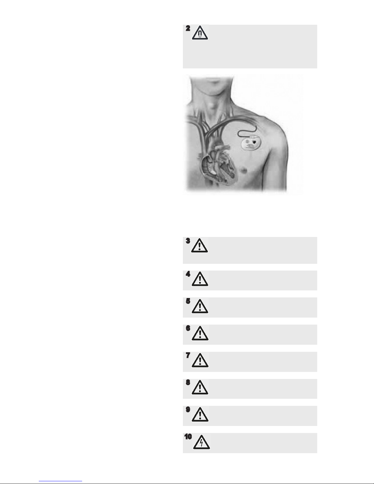
• Persons who have an implanted pacemaker:
– Must stay away from the pump with magnetic coupling and parts of the magnetic coupling
– May not work on or with any of the magnetic parts
Safety equipment
• Provide the following safety equipment and verify its functionality:
– For hot, cold and moving parts: on-site safety guards for the pump
– For possible electrostatic charges: provide the necessary grounding
– If there is no pressure relief valve in the pump: Provide an appropriate safety valve on the pressure
side between the pump and the rst shut-off device
Warranty
• Obtain the manufacturer’s approval prior to carrying out any modications, repairs or alterations during the
warranty period.
• Only use genuine parts or parts that have been approved by the manufacturer.
Drive system
For pumps delivered without a drive system, comply with the following requirements for the drive system:
• When using three-phase asynchronous motors, observe IEC 60034-30-1.
• Power of the drive according to EN ISO 5199 is recommended (EN ISO 5199 also applicable for drives of
screw pumps).
• Use coupling guard with the following requirements:
– Fastening elements must be connected to the pump unit in undetachable design (cannot get lost).
– Safety distances against the reaching of hazardous areas according to EN ISO 13857 must be
complied with.
Obligations of the operating company
• All directions given on the pump must be followed (and kept legible), e.g. the arrow indicating the sense of
rotation and the markings for uid connections.
• Pump, coupling guard and components:
– Do not step on them or use as a climbing aid
– Do not use them to support boards, ramps or beams
– Do not use them as a xing point for winches or supports
– Do not use them for storing paper or similar materials
– Do not use hot pump or motor components as a heating point
– Do not de-ice using gas burners or similar tools
• Do not remove the safety guards for hot, cold or moving parts during operation.
• Use personal protective equipment whenever necessary.
• Only carry out work on the pump while it is not running.
• Isolate the motor from its supply voltage and secure it against being switched back on again when carrying
out any tting or maintenance work.
• Reinstall the safety equipment on the pump as required by regulations after any work on the pump.
• With an implanted pacemaker:
– Stay at least 1 meter away from the pump with magnetic coupling or parts of the magnetic coupling.
– Do not work with or on the magnetic parts.
Page 4

ACG8 2018.01 en-GB, ID-No.: 163-043/A
www.imo.se
4
Specic hazards
Hazardous pumped liquids
• Observe the safety regulations for handling hazardous substances (e.g. hot, ammable, poisonous or potentially harmful) when handling hazardous pumped liquids.
• Use personal protective equipment when carrying out any work on the pump.
• Noise level:
– Check individual pump series noise level in respective Product Description
Magnetic eld
The magnetic eld of the magnetic coupling can destroy products that are sensitive to magnets.
These include:
• Pacemakers
• Plastic identity cards with magnetic strips
• Credit and check cards
• Electric, electronic and precision mechanical devices (such as mechanical and digital clocks, pocket
calculators, hard disks)
Page 5
ACG8 2018.01 en-GB, ID-No.: 163-043/A
www.imo.se
5
max. 90°
min. 60°
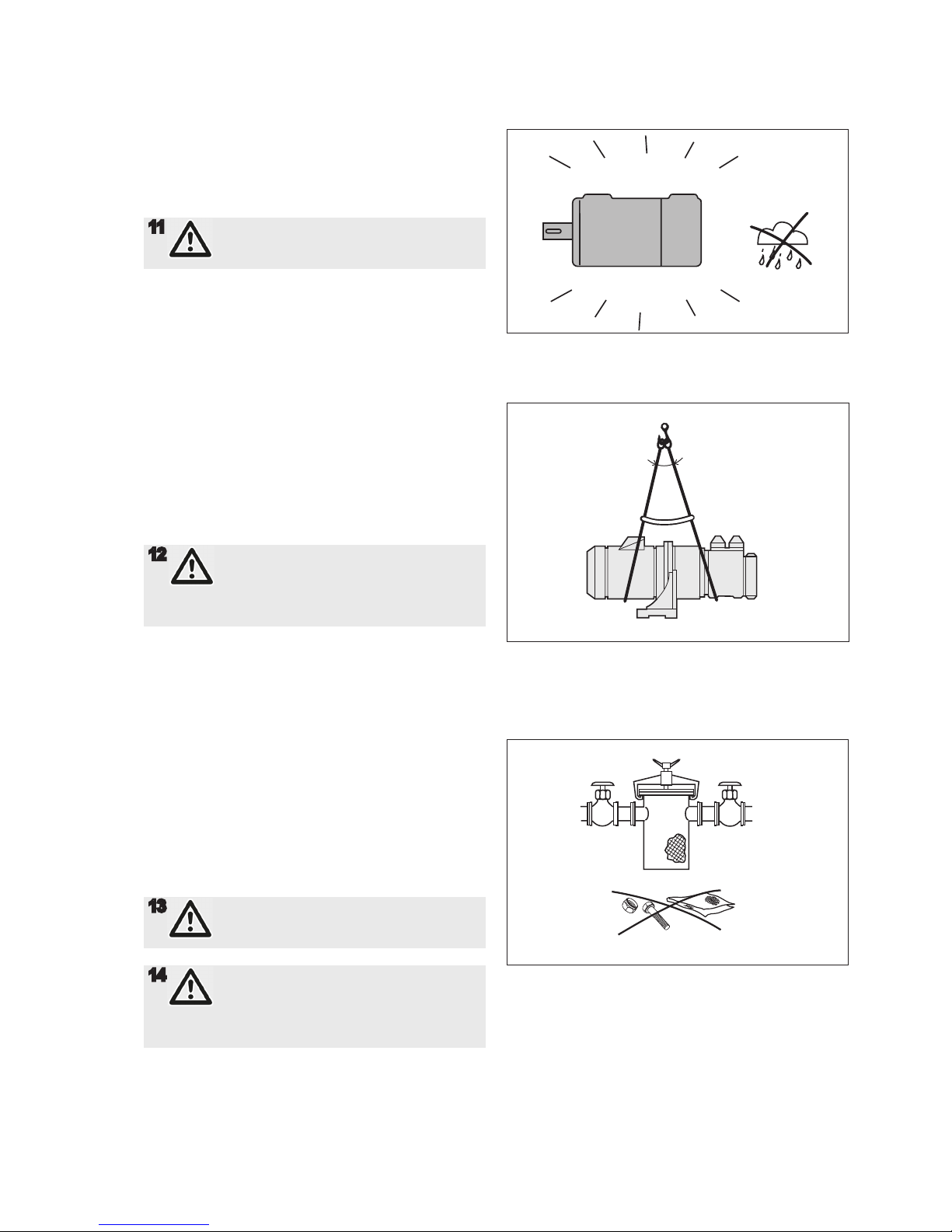
Fig 2. Lifting the pump
Design limitations and technical data for each pump
are found in the Product description. Installation of IMO
AB low pressure pumps does not require special skills.
However, these instructions presume that the work is
carried out by experienced tters!
11
Failure to comply with these instructions
may cause damage and personal injury
Transport and storage
Always protect the pump against ingress of water
and other impurities. Store the pump in a clean, dry
and warm environment. The pump is delivered with
the internals oiled and with protective covers over the
pipe connections and drain openings. These covers
should remain in place for as long as possible during
the mounting and installation procedure but must be
removed before start up.
Lifting of pump
Lifting of the complete pump unit with the lifting device
attached to the motor, should be avoided as the motor’s
lifting provisions may not be able to carry the combined
weight of the pump and motor.
12
All pumps should be lifted with straps
securely attached to the pump or pump
unit, so that the center of gravity is located
between the straps in order to avoid
tipping of the pump.
Strainer
The pump has to be protected from foreign matters
such as weld slag, pipe scale, etc., that could enter the
pump via the suction line. If the cleanliness of the system cannot be guaranteed, a strainer must be installed
in the inlet pipe near the pump. For practical reasons
a suction strainer with 0.8-2.0 mm mesh openings is
recommended.
The size of the strainer should be selected so that it is
large enough to allow adequate pressure at the pump
inlet. The pressure drop across the strainer should
preferably not exceed 0.1 bar at max. ow rate and normal operating viscosity. A vacuum gauge between the
strainer and the pump inlet is recommended to indicate
when the strainer needs cleaning.
13
All work carried out on the pump has to be
performed in such a manner that risks for
personal injury are observed.
14
Lifting a complete pump unit, using
slings or hooks attached to the pump or
connecting frame may be dangerous since
the centre of gravity of the pump unit may
be higher than the points of attachement.
Fig. 3 Strainer
Installation
Fig 1. Keep dry and clean
Page 6
ACG8 2018.01 en-GB, ID-No.: 163-043/A
www.imo.se
6
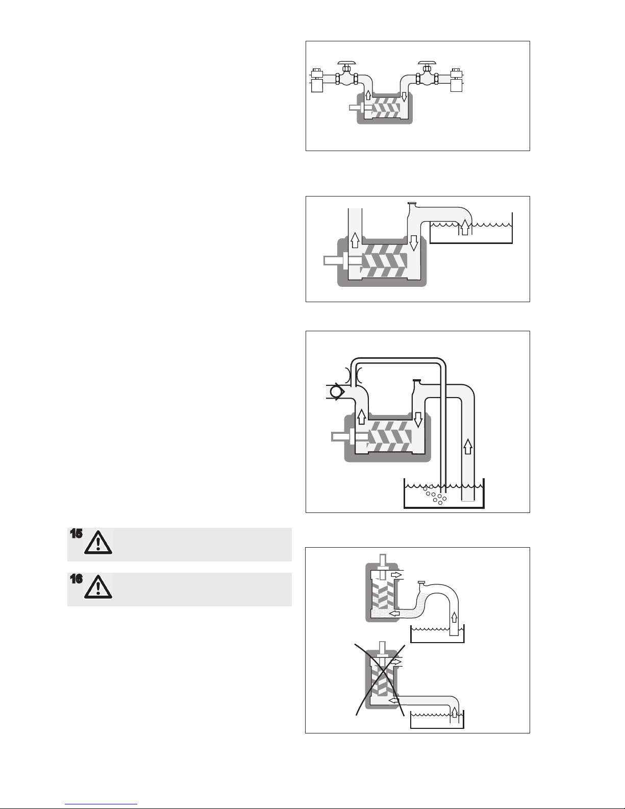
Fig. 6 Deaeration
Pipe connections
The pipe work shall be installed and supported so that
no pipe stresses are transferred to the pump body.
The pipe forces and torque transferred to the pump
shall be in accordance with ISO 14847. The pipe work
should be tight in order to avoid leakage and inltration
of foreign particles and/or air. Shut off valves should be
installed in both suction and discharge pipes, so that
the pump can be hydraulically isolated.
Suction line
The suction pipe should be designed so that the total
pressure drop, measured at the pump inlet ange, does
not exceed the suction capability of the pump. Make a
proper calculation of the suction line including components such as valves, strainer, pipe bends etc. Generally, the pressure drop in the suction line should be as
low as possible, which is achieved if the suction pipe is
short, straight and has a suitable diameter. The velocity
in the suction line should be kept in the range 0.5 - 1.2
m/s. For L.O. circulating systems, we recommend to
keep it as low as possible. The suction line must be
equipped with a port that allows lling the pump before
start.
Discharge line
The discharge line should be dimensioned to keep the
velocity in the range 1 - 3 m/s.
Deaeration
In installations with negative suction head, where the
pump might be started against a pressurized system, a
deaeration pipe with an orice (2-3 mm is recommended) has to be installed. The deaeration pipe should be
connected to the outlet pipe’s highest point. This must
also be installed when the pump is used as a stand-by
pump.
Liquid trap
In some mounting arrangements the pump may not
retain the liquid at stand still. In such installations the
suction pipe should be arranged so it forms a liquid trap
together with the pump, keeping the pump half lled
with liquid.
Fig. 4 Pipe connections
Fig. 5 Suction Line
15
When handling liquids that may harm skin
use gloves and/or protective clothing
16
When handling liquids shich may involve
re hazards appropriate precautions to
avoid danger are to be taken.
Fig. 7 Liquid trap
Page 7
ACG8 2018.01 en-GB, ID-No.: 163-043/A
www.imo.se
7
bar
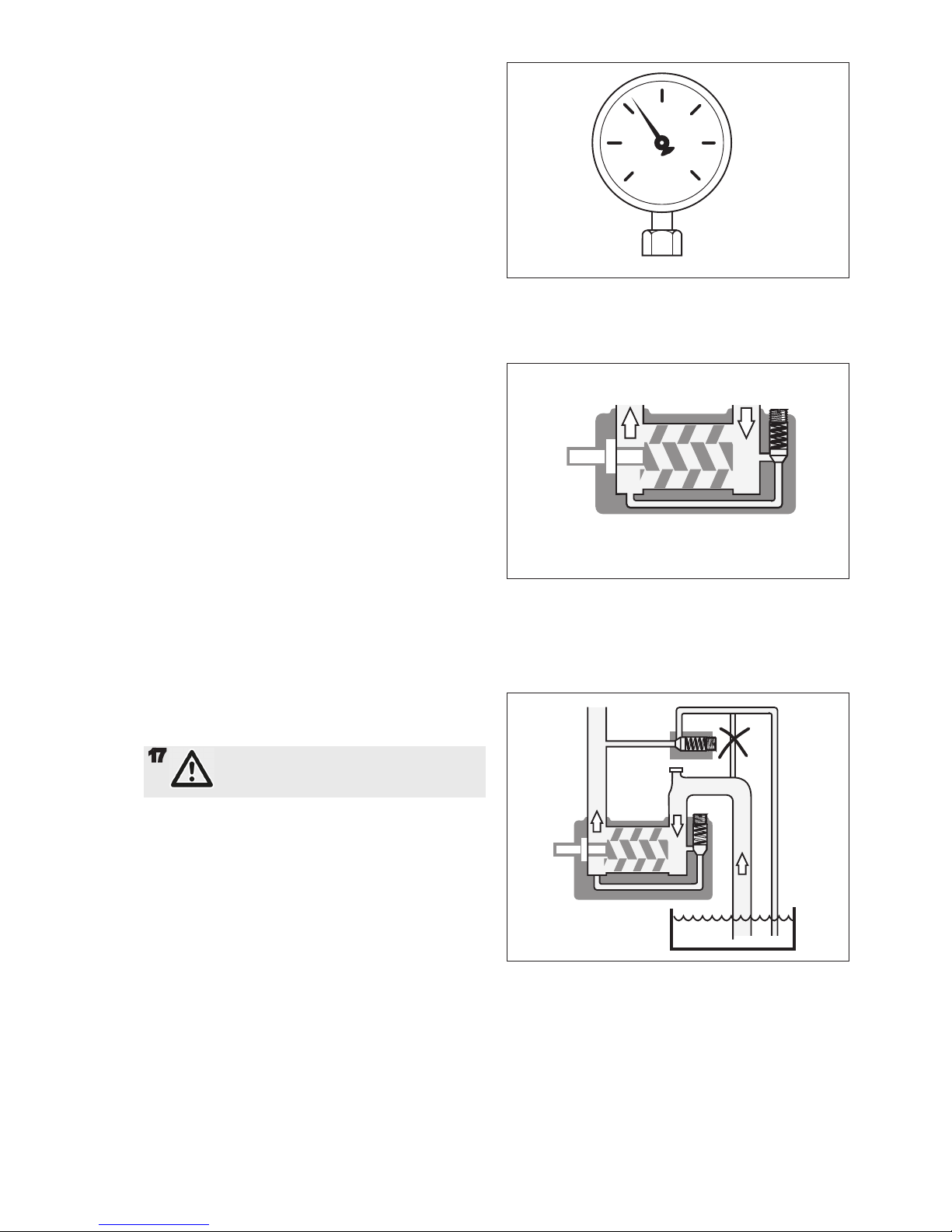
Gauges
Gauges for monitoring the pump’s working conditions
are recommended. These gauges should be placed
readable as close to the pumps in- and outlet anges
as possible. On the ACG Optiline standard pumps there
are gauge connections for both in- and outlet.
Pressure relief valve
All systems with screw pumps must be equipped with
a pressure relief valve installed immediately adjacent
to the pump. In the standard versions of IMO ACG
Optiline pumps, this pressure relief valve is an integral
part of the pump to protect the system against excess
pressure. When liquid is circulated through the valve it
heats up in proportion to the set pressure level and the
percentage of by-passed liquid. 100% bypass can only
be tolerated for less than about 3 minutes, 50 %by-pass
generally for unlimited periods of time. If more than
50% recirculation is anticipated, a value specic to each
application should be determined by closely monitoring
the pump body temperature. If the pump is operating in
line with a separate pressure control valve
(see g. 9), the setting of the relief valve should be high
enough so as not to interfere with the control valve.
Likewise, if two pumps are operating in parallel, the
setting should be such that interference between the
two valves is avoided.
Also remember that a total bypass by the pumps inter-
nal relief valve will cut of the cooling ow to the pumps
magnetic coupling and cause an overheating with
destroyed magnets as a result quite fast.
17
Oil leakage may make the oor slipper y
and couse personal injury.
Fig. 8 Gauges
Fig. 9 Pressure Relief Valve
Fig. 10 External control with presssure relief valve
Page 8
ACG8 2018.01 en-GB, ID-No.: 163-043/A
www.imo.se
8
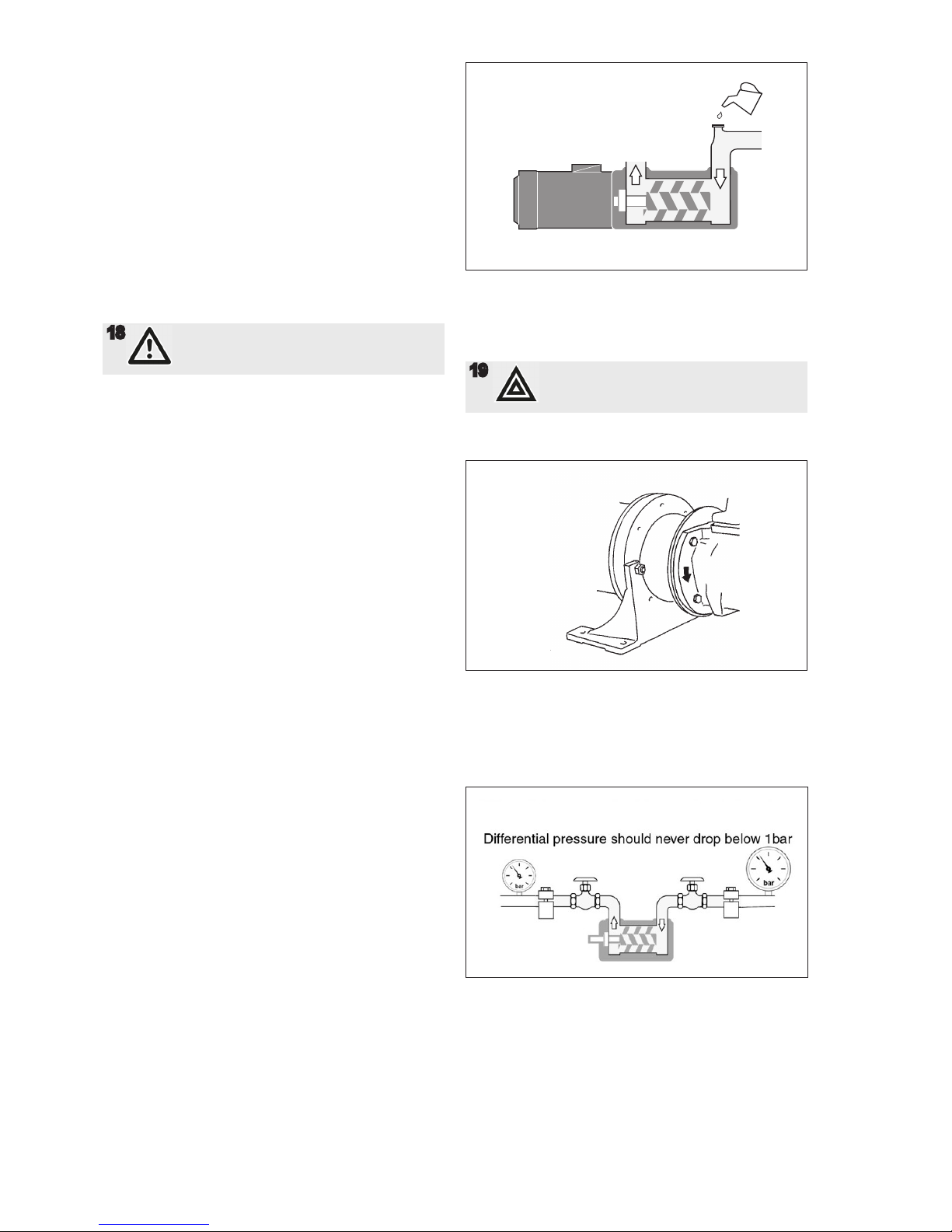
Pressure testing and ushing
The system must be ushed and pressure tested before
connecting the pump. If corrosive liquid, such as water
is used, the system must be thoroughly drained, dried
and protected against corrosion after having been
ushed.
Before starting:
After installation and whenever it can be assumed that
the pump has been emptied, the pump must be thor-
oughly lled with liquid. See g 11.
18
Make sure the prime mover is locked out
and can not be started accidentally.
Direction of rotation
When the pump is ready to be started, switch the motor
briey on and off and check that the drive motor rotates
in the correct direction as indicated by the rotation
arrow. The arrow is placed on the side of the front cover
5010 as well as on riveted steel plates on the connecting frame 003.
Differential pressure
Differential pressures bellow 1 bar is strictly forbidden
as the magnetic coupling under these conditions may
loose its cooling ow and cause an overheating of the
magnetic coupling with a risk of a potential re as a
result. We do strongly recommend magnetic coupled
pumps to be equipped with a differential pressure
monitoring device that stops the pump automatically if
the differential pressure for some reason should drop to
below 1 bar.
Air in the pumped uid
It is forbidden to use the ACG Optiline pump with uids
that contains more than 0,2% of air due to the risk of
ignition during an eventual overheating of the pump.
Fig. 11 Filling the pump
Fig. 12 Direction of rotation
Fig. 13 Differential Pressure
19
Don't mix up with arrow for inlet and
outlet!
Startup
Page 9

ACG8 2018.01 en-GB, ID-No.: 163-043/A
www.imo.se
9
Problem Cause What to do
Wrong direction of rotation
- Electric cables to motor wrongly
connected.
Reverse the terminal connection on
electric motor.
20
Connecting and disconnec-
ting of electric cables must
be done only by personnel
authorized to do such
work.
The pump cannot be
primed
- Wrong direction of rotation.
- Suction line is not open or pressure
drop in the suction line is too high.
- Major air leakage into the suction
line.
- The pump cannot evacuate the air
through the discharge line due to
excessive counter pressure.
See above.
Check all components in suction line.
The inlet condition should be checked
with a vacuum gauge at the pump inlet.
Check the suction line.
See the chapter on Deaeration
(see page 22).
No ow - The pump is not primed.
- The pressure relief valve is set below the counter pressure.
See above.
Readjust the pressure relief valve to a
value above counter pressure.
Flow too low - The pressure relief valve is set too
low (Discharge pressure also low).
- Something is restricting the ow in
the suction line. (This would usually
cause noise).
- The pumped liquid contains a significant amount of compressible gas,
such as free air. (This would usually
cause noise).
Readjust the pressure relief valve
Check all components in the suction
line (strainers, valves etc.).
See the chapter on Noise and Vibra-
tion. ( Page 11).
Pressure too low - The pressure relief valve is set too
low.
- Counter pressure in the discharge
line is too low due to a major leakage.
- The valve piston is stuck in open
position.
- Something is restricting the ow in
the suction line. (This would usually
cause noise).
- The pumped liquid contains a significant amount of compressible gas,
such as free air. (This would usually
cause noise).
- A too small pump has been chosen.
Readjust the pressure relief valve.
Check the components in the discharge
line inclusive the recipients.
Check the valve. See Maintenance and
Service instruction for respective pump.
Check all components in the suction
line (strainers, valves etc.).
See the chapter on Noise and Vibration. (Page 11).
Contact your IMO AB representative.
Trouble shooting
Page 10
ACG8 2018.01 en-GB, ID-No.: 163-043/A
www.imo.se
10
Pressure too high - The pressure relief valve is set too
high.
- The oil is too cold (or has higher
viscosity than anticipated).
- Counter pressure in the discharge
line is too high.
Readjust the pressure relief valve.
Reduce the pressure setting until operational temperature has been reached.
Check the discharge line.
Drive motor difcult to
start or tends to stop by
tripping the motor overload relay
- Counter pressure too high.
- Liquid too cold.
- Motor is undersized for the prevailing conditions.
- Electrical power supply faulty.
- Motor overload relay set too low or
is faulty.
- Incorrect setting of Y/D starter.
See above: Pressure too high.
Readjust the pressure relief valve to a
lower value. Thus the power consumption for the pumping is relieved and
overloading due to the high viscosity
may be avoided. When the liquid has
reached normal temperature and thus
ows easily, the relief valve is reset to
normal pressure.
Check the motor.
Check the motor and motor connection.
Readjust or replace the relay.
Readjust the setting of the starting
sequence. The time before the motor
overload relay is tripped should not
exceed 10-15 seconds.
Noise and vibration
21
Monitor the
pump function
and shut down
if any sign of
malfunction is
noticed
- The ow to the pump is insufcient.
- Insufcient support of pipe work.
- Bad alignment
- Air leakage into the suction line.
- Free air in the liquid or gas cavitation.
- Faulty electrical supply.
See chapter: The ow is too low.
Check for pipe vibrations in the pump
connections. Check that the pipes are
sufciently clamped.
Check alignment, see page 4.
Check the suction line for air leakage.
For pumps with Tuning:
Contact your IMO representative or
IMO service department.
Check all three phases of the supply.
Page 11
ACG8 2018.01 en-GB, ID-No.: 163-043/A
www.imo.se
11
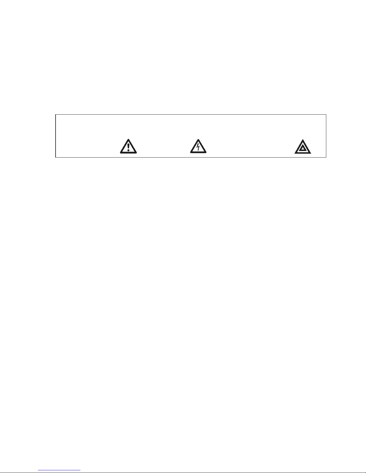
Indentication of safety instructions
Non complience of safety instruc-
tions identied by the following
symbol could affect safety for
persons
Safety instructions where
electrical safety is invol-
ved are identied by:
Safety instructions which shall be considered
for reasons of safe operation of the pump
or pump unit and/or protection of the
pump or pump unit itself are marked
by the sign:
Introduction
A screw pump from IMO is a quality product that is designed for a long problem free operation in tough environments. As all other mechanical products they do however requires a certain grade of maintenance and service in
order to guarantee a faultless and economic favourable operation.
A recommendation is to go through the pump each 5 year in order to replace wear details such as ball bearings and
certain gaskets and o-rings. A relatively small review of a screw pump from IMO means that the pump in most of
the cases will be in a condition “as new” and therefore give the operator another long and problem free operation.
Maintenance and Service
Page 12

ACG8 2018.01 en-GB, ID-No.: 163-043/A
www.imo.se
12
Explanations:
G012: Rotor set
G054:G012+G057 +
pos. no 122
G057: Joint kit
G070:Valve element
G098:Magnetic cou-
pling
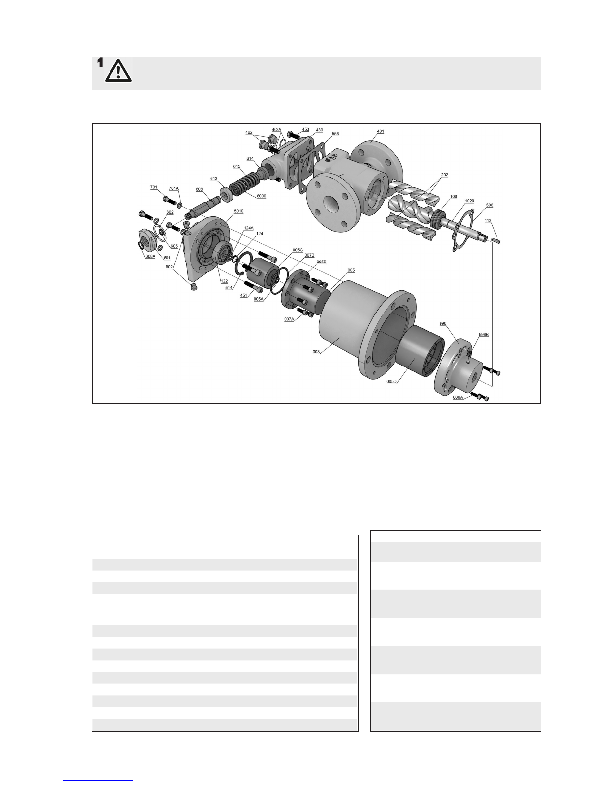
Pos Included components in Spare part sets
No Designation Qty G012 G054 G057 G070 G098
002 Motor 1
003 Connecting frame 1
004 Angle bracket 1
005 Magnetic coupling complete 1 x
005A Retaining ring 1 x x x
005B Sealing can 1 x
005C Inner magnetic rotor 1 x
005D Outer magnetic rotor 1 x
006A Screw 4
007A Screw 6/8
007B O-ring 1 x x x
1020 Power rotor 1 x x
113 Shaft key 1 x x
122 Ball bearing 1 x
124 Retaining ring 1 x x
124A Support ring 1 x x
202 Idler rotor 2 x x
401 Pump body 1
451 Screw 4/6
453 Screw 4
462 Plug 2
462A Sealing washer 2 x x
480 Valve housing 1
5010 Front cover 1
502 Plug 2
506 Gasket 1 x x
514 Retaining ring 1 x x
556 Gasket 1 x x
601 Valve cover 1 x
602 Sealing washer 1 x x x
605 O-ring 1 x x x
608 Valve spindle 1 x
608A Retaining ring 1 x
612 Regulating nut 1 x
614 Valve piston 1 x
615 Valve spring 1 x
701 Screw 4
701A Washer 4
702 Screw 4
702A Washer 4
703 Screw 3
703B Nut 3
998 Drive hub 1
998B Screw 1
List of components
Valid for all ACG Optiline Generation 8 pumps with sizes 045, 052, 060 & 070 and leads K, N & D
With version codes NHBP, NJBP, NKBP, NLBP & NMBP.
Page 13
ACG8 2018.01 en-GB, ID-No.: 163-043/A
www.imo.se
13
1
Before commencing any work, read this instrucion carefully! Failure to comply with these instrutions
may cause damage and personal injury!
For more information about the pumps identication code, technical data and performance we refer to the ACG
Product description.
Recommended Spare Parts
Kits and tool kits
Every shutdown for service of a plant is
costly. The time for repair should therefore be limited to a minimum which can be
accomplished by keeping a spare pump.
The changed pump can later be repaired at
a suitable place and can then be used as a
spare pump. For maintenance the following
spare parts kits and tools are recommended:
Ordering Code
Part numbers for pump size
Item Spare Parts sets 045 052 060 070
G012 Rotor set D-lead 193023
N-lead 193015 193 017 193019 193021
K-lead 193016 193018 193020 193022
G054 Major kit =
G012+G057 +
pos.no.12 2
- - - -
G057 Joint kit 193031 193032 193033 193034
G070 Valve element 190990 190990 190984 190984
G098 Magnetic coupling H 193035 193035 - J 193036 193036 - K 193037 193037 1930 40 193043
L 193 038 193038 193041 193044
M 193039 193039 193042 193045
122 Ball bearing 192855 192855 192827 192827
480 Valve housing 191022 191025 191028 191031
Kit Contents To be used for
G057 Gaskets,
o-rings etc.
Dismantling of the
pump
G012 Rotorset Repair after major
breakdown or
great wear
122 Ball bearing Repair after major
breakdown or
great wear
193128 Guide pins
pump size 045
For dismantling
and assembly of
the pump
193129 Guide pins
pump size 052
For dismantling
and assembly of
the pump
19313 0 Guide pins
pump size 060
For dismantling
and assembly of
the pump
193131 Guide pins
pump size 070
For dismantling
and assembly of
the pump
Exploded view
Page 14
ACG8 2018.01 en-GB, ID-No.: 163-043/A
www.imo.se
14
Service intervals
The intervals for inspection and replacement of wear
parts vary greatly with the properties of the pumped
liquid and can only be determined by experience. All
internal parts of the ACG Optiline pump are lubricated
by the pumped liquid. Pumping liquid which contain
abrasive materials, or liquid that is corrosive, will significantly reduce service life and call for shorter service
intervals. Wear in the pump will normally show as:
• Vibration
• Noise
• Loss of capacity
• Reduction in ow/pressure
• Loss of the magnetic power
We recommend planned inspections and/or overhaul
at regular intervals, not exceeding 5 years. It is recommended to always have the spares included in joint
spare part kit G057 together with the ball bearing 122
available for a planned inspection.
Inspection of rotors
To reach the idler rotors in a quicker way than described in the dismantling section, loosen the rear cover
(480) with the valve. Screw out the idler rotors backwards. Internal clearances in the pump, which are vital
for its proper function, may have been affected by wear.
Acceptable wear can be determined only by experience
of the actual application. As a rule of thumb the following max clearance values may apply: Between rotor
and bores: 0.2 mm, Between rotor anks: 0.4 mm For
light duties (low pressure, medium viscosity) even big-
ger clearances may be acceptable but for low viscosity/
high pressure duties the limit will be lower. Also watch if
there are major scratches on these parts.
Inspection of the magnetic coupling
The magnetic coupling with all its components is considered to be maintenance free if operated and mounted according to our instructions.
The lifetime of the magnets is well within the lifetime of
the pump and exchange of the magnets is only necessary if a major breakdown has occurred as a result of
for example excessive amounts of dirt or particles in the
pumped uid.
Common aspects whit magnetic
couplings
Permanent magnetic couplings generate a strong
magnetic eld. The installation must be carried out only
by trained staff that has the understanding of how a
magnetic coupling acts and all the safety precautions
related to it. All installation instructions must be strictly
followed. Modications or changes to the magnetic coupling or its components are not to be allowed under any
circumstances. IMO does NOT take any responsibilities for damages caused by improper use or damages
related to this.
Magnetic data carriers such as bank cards, oppy disks
etc may become unreadable and should always be kept
separated from the magnetic eld.
DANGER
Installations and maintenance must always take place
during complete shutdown in an un-pressurised condition. The drive unit must be secured against inadvertent
switching on by means of blocking the electrical supply
to the electric motor in order to avoid serious injuries
due to rotating parts.
2
ATTENTION! In areas where permanent
magnetic couplings are handled or
stored with open access, persons with
heart
pacemakers
should keep a distance
of 3 meters. For permanent magnetic
couplings assembled within a pump a
safety distance of 3 meter is sufcient.
Precautions prior to starting
maintenance on the pump
3
If the pumps operating temperature
exceeds 60°C, let the pump cool off before
any service, maintenance or dismantling
work is commenced to avoid burn injury
4
All work carried out on the pump has to be
performed in such a manner that risks for
personal injury are observed!
5
When handling liquids that may harm skin,
use gloves and/or protecting clothing!
6
When handling liquids which may involve
re hazard appropriate precautions to
avoid danger are to be taken.
7
In case of failure for system with elevated
pressure, uid jets may cause injury and/
or damage.
8
Oil leakage may make the oor slipper y
and cause personal injury.
9
Before any maintenance work, ensure that
the driver is deenergized and the pump
hydraulically isolated.
10
Connecting and disconnecting of
electrical cables must be done only by
personnel authorized to do such work.
Page 15
ACG8 2018.01 en-GB, ID-No.: 163-043/A
www.imo.se
15
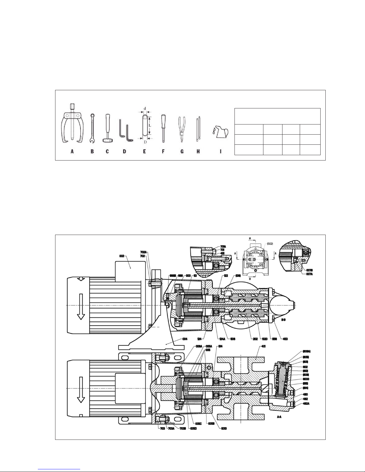
List of tools necessary for dismantling and reassembly
A = Puller
B = Spanner various sizes
C = Plastic mallet
D = Allen keys various sizes
E = Mounting Sleeve for ball bearing (sizes - see table)
F = Screw driver
G = Circlip pliers
H = Guide Pins (for ordering code, see table page 5)
J = Oil can
Sectional View
Dismantling and reassembling the
pump
Mounting sleeve
dimensions (mm)
ACG size d-min D L-min
045 - 052 21 32 ±3 110
060 - 070 36 50 ±3 145
Page 16
ACG8 2018.01 en-GB, ID-No.: 163-043/A
www.imo.se
16
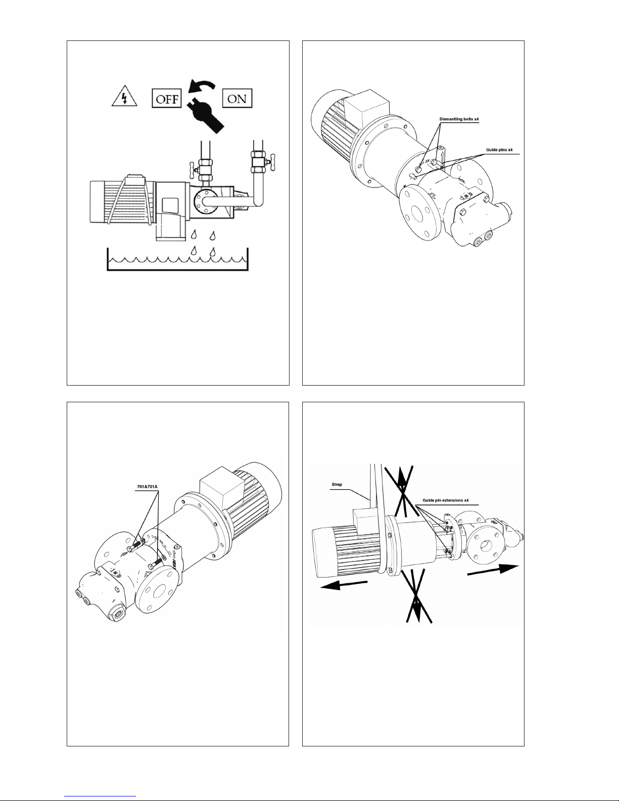
Dismantling
A.
• Turn the electricity OFF.
• Close the valves.
• Disconnect the electric motor.
• For horizontal installation drain the pump by
loosen screws 453 3-4 turns and loosen valve
housing 480.
B.
• Remove the 4 bolts 701 and the washers 701A
C.
• Mount the rst half of the 4 guide pins which
comes in two parts through the pumps front
cover into the connecting frame.
• Attach the dismantling bolts and slowly start to
tight them until the pump is separated from the
electrical motor.
• Continue to tight the bolts while making sure
that the pump and the electric motor with its
connecting frame is in a straight line with each
other.
D.
• Mount the extension guide pins when it is possible and continue to separate the pump from
the electrical motor in an straight line in order to
avoid damages on the magnets.
• The use of a strap or similar devices on the
electrical motor in order to stabilize and secure
the package from the magnetic force is recommended.
Page 17
ACG8 2018.01 en-GB, ID-No.: 163-043/A
www.imo.se
17
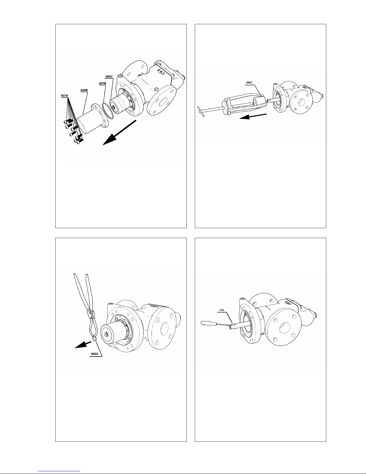
E.
• Unscrew the bolts 007A
• Pull out the sealing can 005B with its o-ring
007B
F.
• Remove the circlip 005A with a suitable plier.
G.
• Remove the inner magnetic rotor with a suitable three arm puller
H.
• Remove the key 113 from the pump shaft.
Page 18
ACG8 2018.01 en-GB, ID-No.: 163-043/A
www.imo.se
18
I.
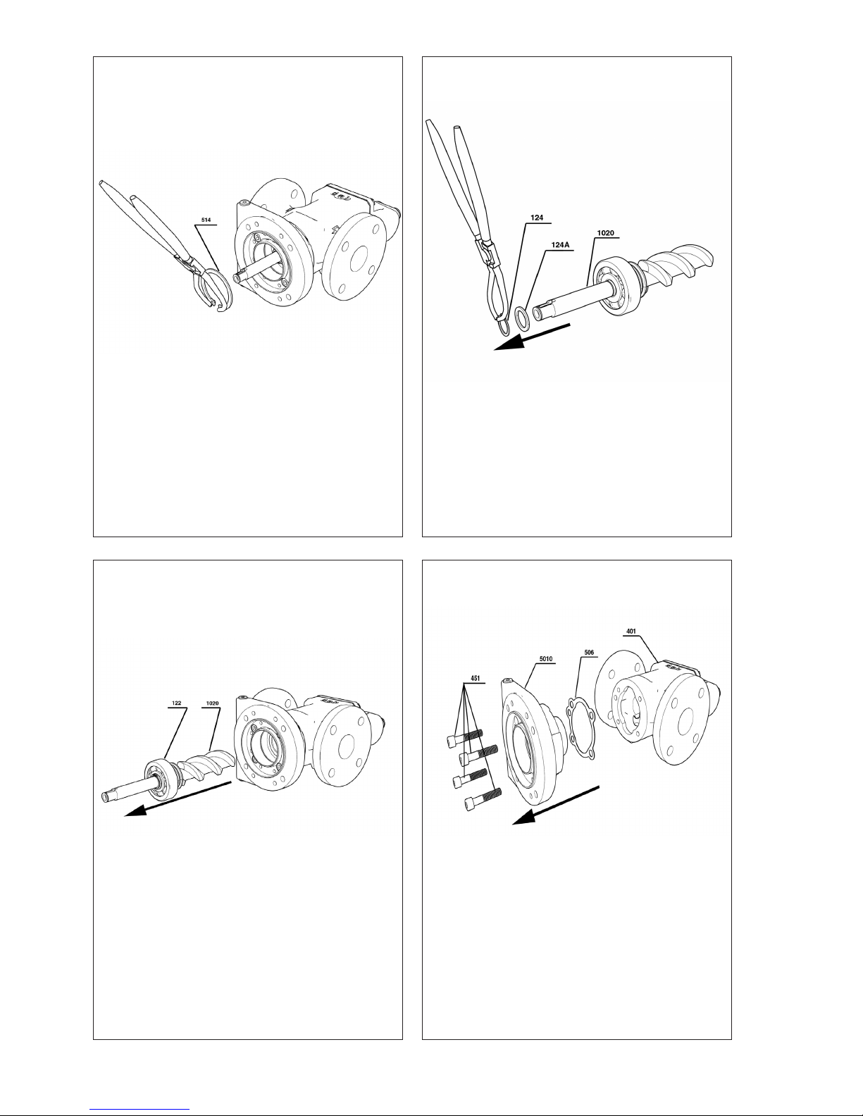
• Remove the circlip 514 from the front cove with
a suitable plier.
J.
• Pull out the power rotor 1020 with its ball bearing 122 by hand force from the pump body.
K.
• Remove the circlip 124 with a suitable plier
from the power rotor 1020.
• Remove the support washer 124A.
L.
• Unscrew the bolts 451 from the front cover
5010
• Separate the front cover 5010 with its gasket
506 from the pump house 401.
Page 19
ACG8 2018.01 en-GB, ID-No.: 163-043/A
www.imo.se
19
M.
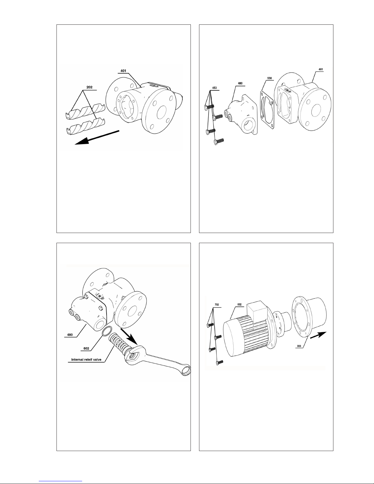
• Pull out the idlers 202 from the pump body 401
by hand force.
N.
• Unscrew the complete internal relief valve by
means of a suitable open spanner and pull it
out from the rear cover 480 together with its
seal ring 602.
O.
• Unscrew the 4 bolts 453 with a suitable spanner and remove the rear cover 480 with its
gasket 556 from the pump body 401
P.
• Unscrew the 4 bolts 702 with a suitable spanner and separate the connecting frame 003
from the electrical motor 002
Page 20
R.
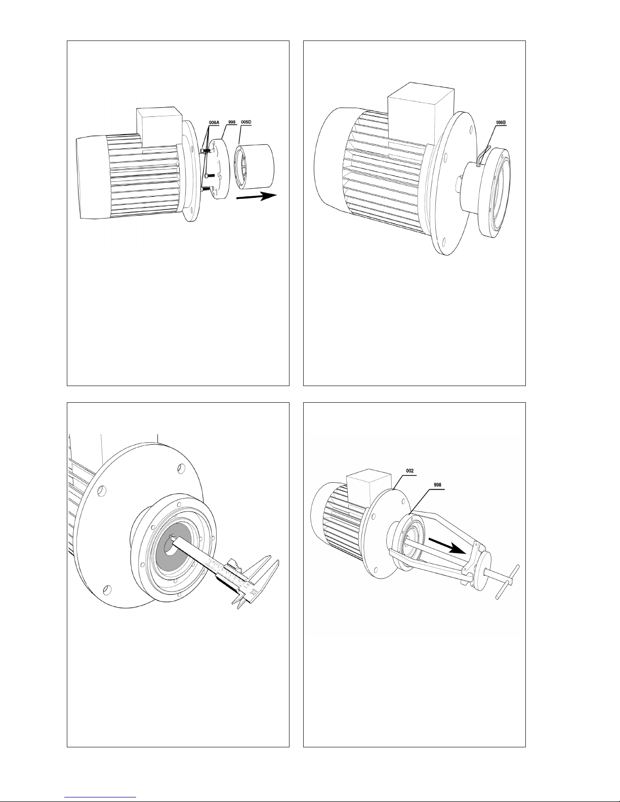
• Measure the distance on the shaft coupling and
note the value so that it can used during the
assembly later on.
ACG8 2018.01 en-GB, ID-No.: 163-043/A
www.imo.se
20
Q.
• Unscrew the bolts 006A with a suitable allen
key and remove the outer magnet from the
coupling 998
S.
• Use a three arm legged puller and remove the
coupling 998 from the electrical motor.
S.
• Unscrew the locking bolt 998B from the coupling 998.
Page 21
ACG8 2018.01 en-GB, ID-No.: 163-043/A
www.imo.se
21
B.
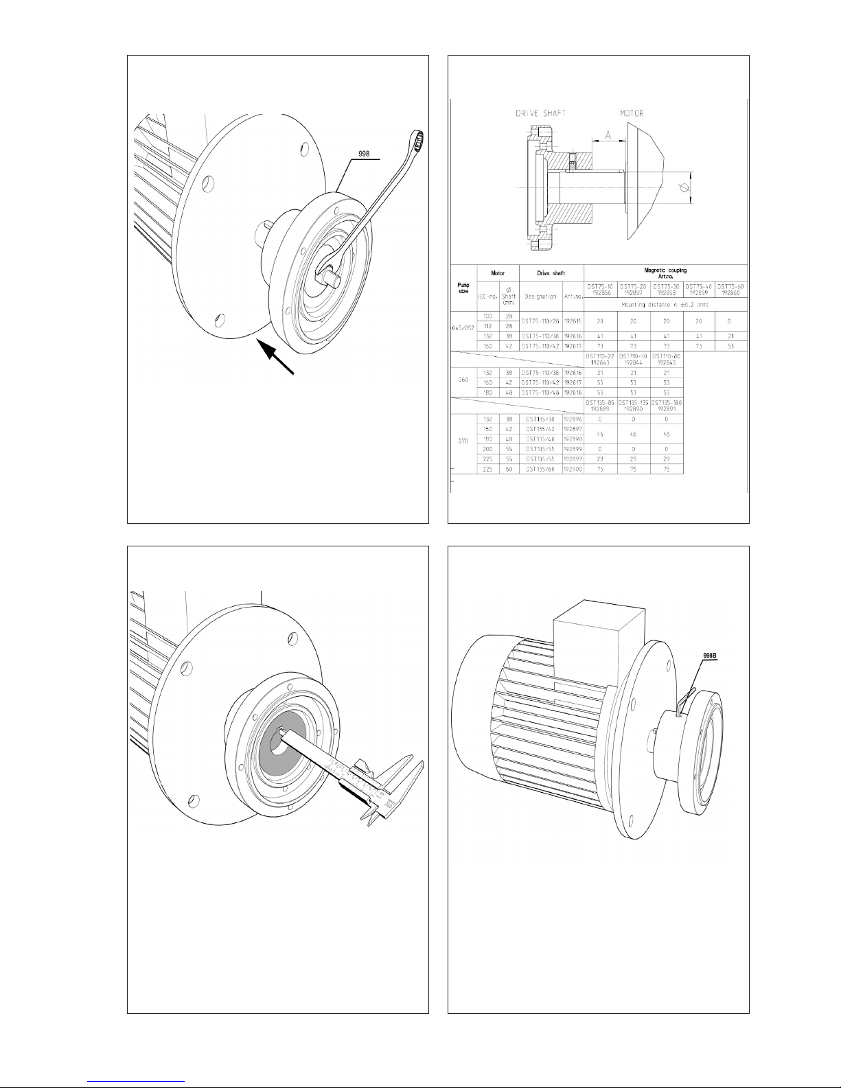
• Measure the distance in order to get the same
as before the coupling was removed.
D.
• Tight the looking bolt 998B with a suitable hexagon key
A.
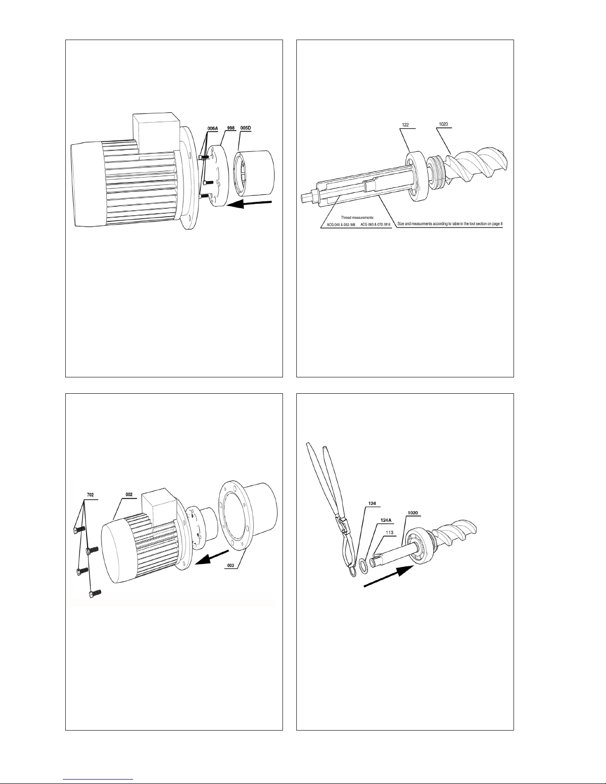
• Mount the coupling half 998 onto the drive
shaft of the electrical motor by means of a big
washer and a threaded pin and a nut that is
tightened in order to press the coupling half
onto the shaft.
NOTE: Do not use a hammer as this can Damage the shaft!
Reassembly
C.
Page 22
ACG8 2018.01 en-GB, ID-No.: 163-043/A
www.imo.se
22
H.
• Mount the washer 124A and slide on the circlip
124 with a suitable plier on the power rotor
1020.
• Mount the key 113 on the power rotor 1020.
E.
• Attach the outer magnet rotor 005D to the
coupling half 998 and tight the screws 006A according to the tightening torque table on page
17 in this manual.
F.
• Attach the connecting frame 003 to the electrical motor 002 by means of tightening the bolts
702 according to the tightening torque table on
page 17 in this manual.
G.
• Mount the ball bearing 122 on the power rotor
1020 with the mounting tool described on page
8, use a threaded pin together with a nut and a
washer and press down the ball bearing on the
shaft carefully. Note: in order to make the ball
bearing to slide on easier it is recommended to
grease the shaft surface.
Page 23
ACG8 2018.01 en-GB, ID-No.: 163-043/A
www.imo.se
23
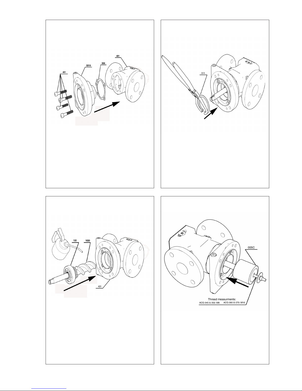
I.
• Mount the front cover 5010 with its gasket 506
onto the pump body 401 with the bolts 451
• The bolts 451 are to be tightened according to
the tightening torque table on page 17 in this
manual.
J.
• Carefully slide the power rotor 1020 with its ball
bearing 122 into the pump body 401 with hand
force. Note: do not forget to lubricate the rotor
prior to the mounting.
K.
• Attach the Circlip 514 with a suitable plier into
the front cover.
L.
• Press the inner magnetic rotor onto the rotor
shaft by means of a threaded pin and a nut/
washer, push it into its nal position by means of
a suitable socket.
NOTE: DO NOT USE A HAMMER AS THIS
CAN DAMAGE THE PARTS!
Page 24
ACG8 2018.01 en-GB, ID-No.: 163-043/A
www.imo.se
24
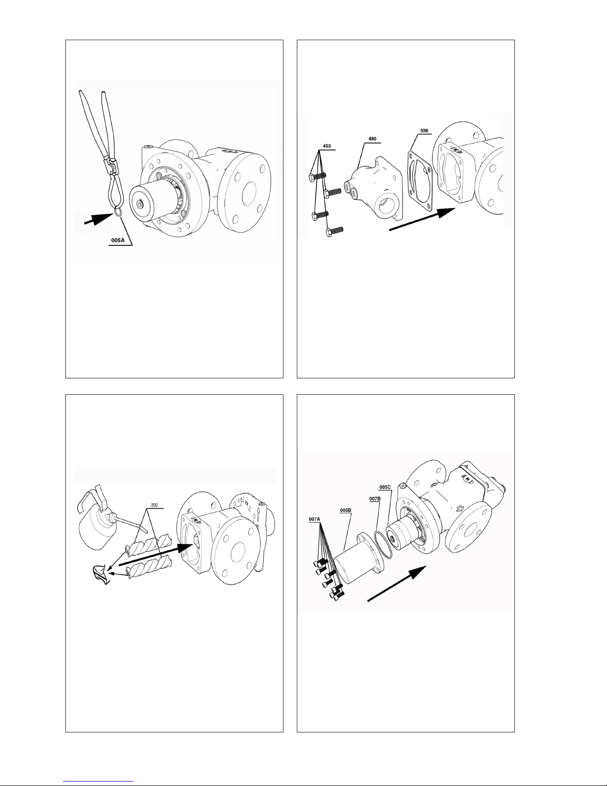
M.
• Mount the circlip 005A with a suitable plier.
N.
• Carefully slide the lubricated idlers into the
pump body
• Make sure that the lubrication slots are pointing
backwards
O.
• Mount the rear cover 480 with its gasket 556
onto the pump body and tight the bolts 453 according to the tightening torque table on page
17 in this manual.
P.
• Mount the sealing can 005B with its o-ring
007B onto the pump and tight the bolts 007A
according to the tightening torque table on
page 17 in this manual.
Page 25
ACG8 2018.01 en-GB, ID-No.: 163-043/A
www.imo.se
25
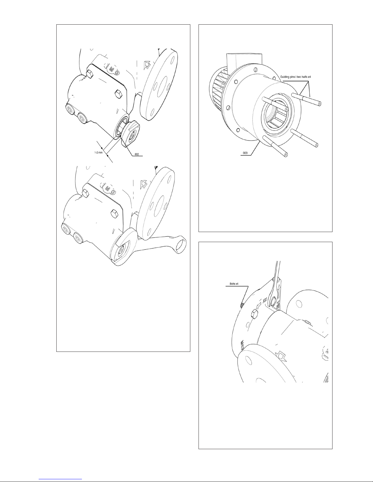
Q.
• Mount the pumps internal relief valve into the
back cover by means of letting the inner thread-
ed ring be mounted rst with a distance to the
outer one of 1-2 mm
• Do not forget to include the seal ring 602
• Tight the nut accordingly with a suitable spanne r.
R.
• Mount the guiding pins into the connecting
frame 003.
S.
• Attach 4 bolts in the pumps front cover in order
to avoid a to rapid mounting due the magnetic
forces that will take place when the pump package is joined.
Page 26
ACG8 2018.01 en-GB, ID-No.: 163-043/A
www.imo.se
26
T.
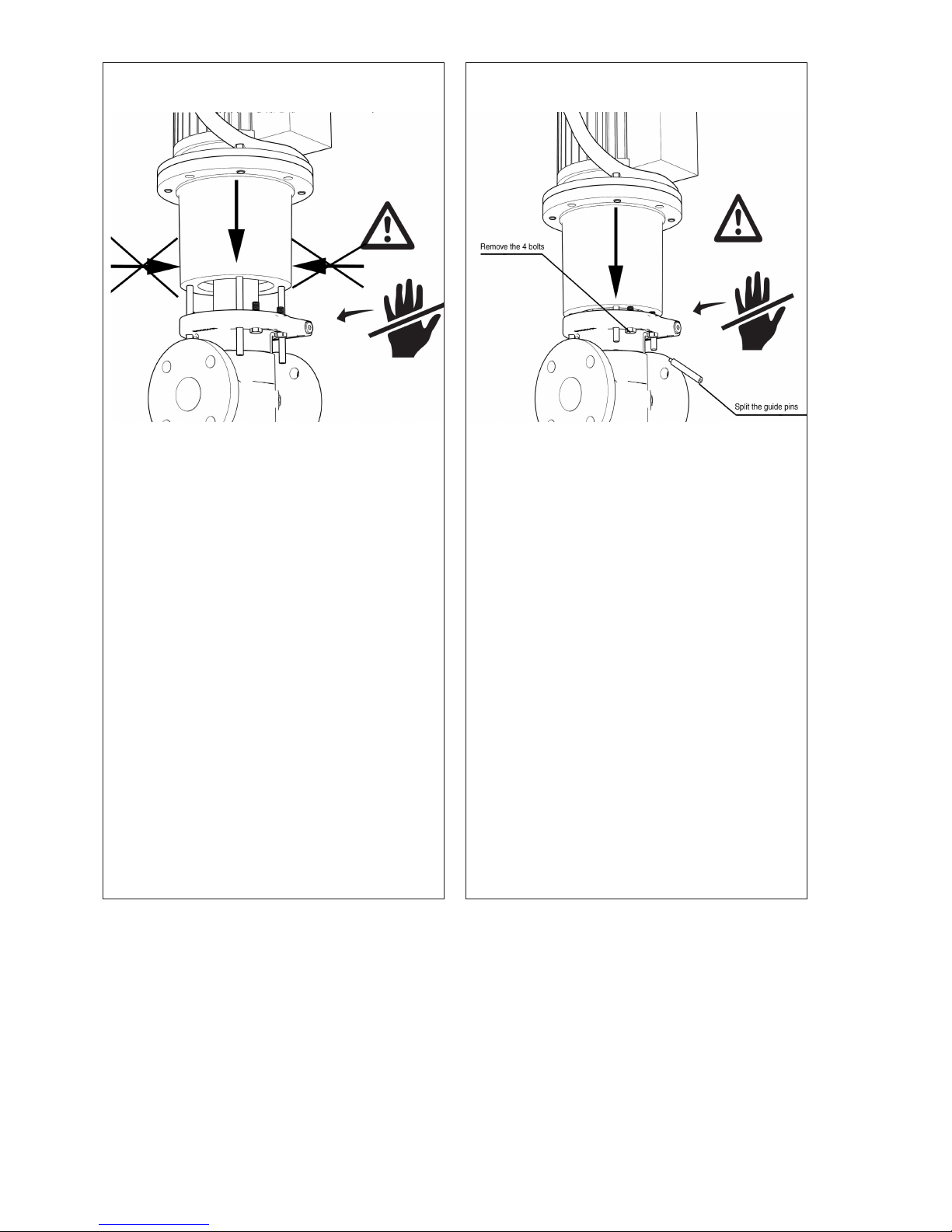
• Slowly lower the electric motor with the connecting frame towards the pump until the stop
bolts touches the frame.
• Avoid side forces that could damage the magnets as it is crucial that the package is connected in a straight line
NOTE: The magnetic forces are very high at
this point and can easily cause severe injuries DO NOT EVER PUT YOUR FINGERS
OR HANDS BETWEEN THE CONNECTING
FRAME AND THE PUMP AS AN ACCIDENTAL SLIP DOWNWARDS EASILY CAN
CRUSH A HAND OR EVEN CUT A FINGER.
U.
• Unscrew the stopping bolts and allow the pump
to completely join with the electrical motor/connecting frame
• Avoid side forces that could damage the magnets as it is crucial that the package is connected in a straight line
• Unscrew the last part of the guide pins.
NOTE: The magnetic forces are very high at
this point and can easily cause severe injuries
DO NOT EVER PUT YOUR FINGERS OR
HANDS BETWEEN THE CONNECTING
FRAME AND THE PUMP AS AN ACCIDENTAL SLIP DOWNWARDS EASILY CAN
CRUSH A HAND OR EVEN CUT A FINGER.
Page 27
Tightening torque (Nm)
Size 045 052 060 070
Pos.No
006A 10 10 10 10
007A 20 20 20 20
451 47 47 81 81
453 47 47 81 81
462 74 74 74 74
502 47 47 47 47
301 13 20 47 47
701 13 20 47 47
702/IEC 100-132 30 30 30 30
702/IEC 160-225 74 74 74 74
703B/IEC 100-132 81 81 81 81
703B/IEC 160-225 197 197 197 197
998B 15 15 15 15
ACG8 2018.01 en-GB, ID-No.: 163-043/A
www.imo.se
27
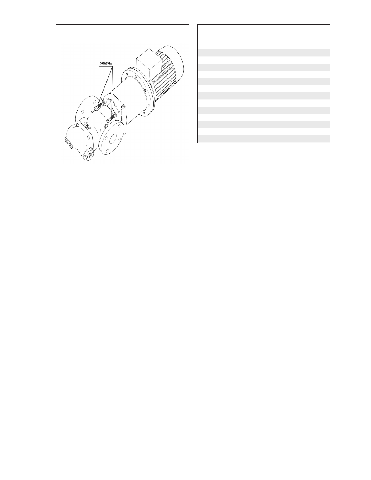
V.
• Tight the bolts 701 with its washers 701A with
a suitable spanner according to the torque
tightening table on this page.
Page 28

ACG8 2018.01 en-GB, ID-No.: 163-043/A
www.imo.se
28
Adress:
IMO AB
Solna Torg 19, 2tr
171 45 Solna, Sweden
 Loading...