

Page 1
INSTRUCTION MANUAL
Manual No. SRM00061
REV 08 (13-0376)
October, 2013
AND
RTS LIST
PA
FOR
_G3D-187, 218, 250 and 312 S ERIES PUMPS
(Idler Cup and Hydrostatic Thrust Designs)
WARNING
The Imo General Installation Operation, Maintenance, and Troubleshooting Manual,
(No. SRM00046), along with this manual as well as all other component manuals
supplied with these type units should be read thoroughly prior to pump installation,
start-up, operation, maintenance or troubleshooting.
1
Page 2
IMPORTANT NOTE
Failure to fill or vent seal chamber as described above may cause damage to seal running
The importance of seal chamber priming cannot be overemphasized. Due to the prevalence
of seal damage and leakage caused by not filling the seal chamber with liquid before
putting a pump in service, this page is located at the beginning of this document.
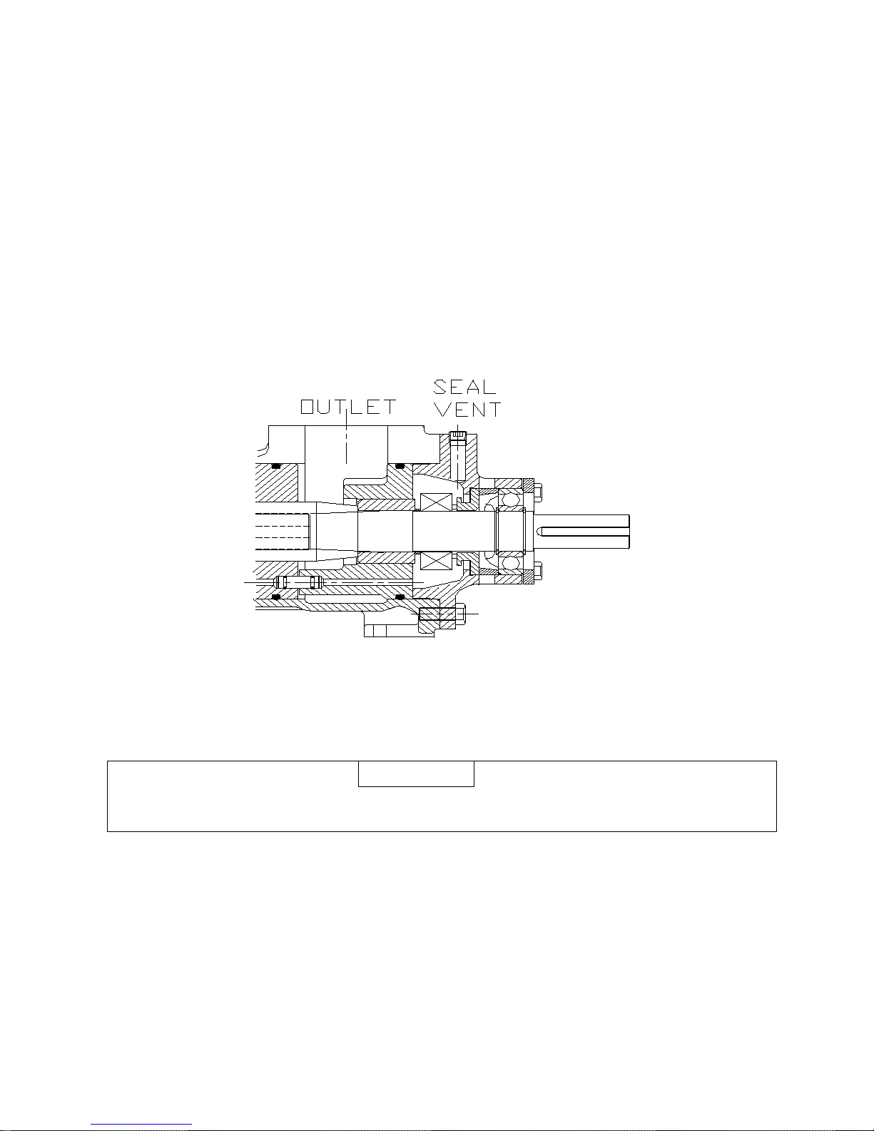
SEAL CHAMBER PRIMING
Fill mechanical seal chamber with liquid to insure seal does not start dry. This can be done by removing seal
vent set-screw and pouring liquid into vent passageway before opening pump inlet. Alternately, seal
chamber can be vented in situations where inlet pressure is above atmospheric by opening inlet and
discharge valves and then loosening seal vent plug to allow positive inlet pressure to push air out of seal
chamber until oil flows from it. See figure below.
Filling or Venting Seal Cavity Using Seal Vent
CAUTION
faces which may result in seal leakage.
2
Page 3
READ THIS ENTIRE PAGE BEFORE PROCEEDING
idental contact with equipment or liquids. Protection should be provided by
Non compliance of safety
Safety instructions
Safety instructions which
by the sign:
ATTENTION
If operation of pump is critical to your business, we str ongly recommend you keep
pump refurbishment after internal inspection can be accomplished.
FOR SAFETY OF PERSONNEL AND TO PREVENT DAMAGE TO EQUIPMENT, THE FOLLOWING
NOMENCLATURE HAS BEEN USED IN THIS MANUAL:
DANGER
Failure to observe precautions noted in t his box can result in severe bodily injury
or loss of life.
WARNING
Failure to observe precautions noted in this box can cause injury to personnel by
acc
user to prevent accidental contact.
CAUTION
ATTENTION
Failure to observe precautions noted in this box can cause damage or failure of
equipment.
instructions identified by
the following symbol
could affect safety for
persons:
where electrical safety is
involved are identified
by:
shall be considered for
reasons of safe operation
of pump and/or protection
of pump itself are marked
ATTENTION
a spare pump or major repair kit in stock at all times. As a minimum, a minor
repair kit (o-rings, gaskets, shaft seal and bearings) should be kept in stock so
Table of Contents
Seal Chamber Priming………………………………………………………………………………….2
Safety and Table of Contents ..................................................................................................... 3
A. General Instructions, introduction, Description of Equipment ................................................ 4
B. Assembly Drawing List and Mechanical Seal Types…………………………………………….5
C. Pump Model Identification, Ordering Instructions .................................................................. 6
D. Operating Limits ................................................................................................................... 7
E. Parts Lists ......................................................................................................................... 8-9
G. Pump Disassembly and Reassembly (Pumps with seals) ................................................... 10
H. Mechanical Seal Information ......................................................................................... 17-23
I. Pump Disassembly and Reassembly (Packing Pumps) ................................................. 24-26
J. Troubleshooting, Field and Factory Service and Parts ........................................................ 26
K. Assembly Drawings ....................................................................................................... 27-35
L. Imo Address and Phone Numbers ...................................................................................... 36
3
Page 4
If installation, operation, and maintenance instructions are not correctly and strictly
damage resulting from failure to comply with instructions.
TM
A. GENERAL INSTRUCTIONS
The instructions found herein cover the disassembly, assembly and parts identification of
_G3D-187, 218, 250 and 312 series pumps. Both the original design with idler cups and the newer
design with hydrostatic idlers are covered.
NOTE: I ndividual contracts may have specific provisions that vary from this manual. Should any
questions arise which may not be answered by these instructions, refer to General
Installation Operation, Maintenance, and Troubleshooting Manual, (No. SRM00046), provided
with your order. For further detailed information and technical assistance please refer to Imo
Pump, Technical/Customer Service Department, at (704) 289-6511.
This manual cannot possibly cover every situation connected with the installation, operation, inspection, and
maintenance of equipment supplied. Every effort was made to prepare text of manual so that engineering and
design data is transformed into the most easily understood wording. Imo Pump must assume personnel
assigned to operate and maintain supplied equipment and apply this instruction manual have sufficient
technical knowledge and are experienced to apply sound safety and operational practices which may not be
otherwise covered by this manual.
In applications where equipment furnished by Imo Pump is to become part of processing machinery, these
instructions should be thoroughly reviewed to ensure proper fit of said equipment into overall plant
operational procedures.
WARNING
followed and observed, injury to personnel or serious damage to pump could
result. Imo Pump cannot accept responsibility for unsatisfactory performance or
B. INTRODUCTION
This instruction manual covers series _G3D-187, 218, 250 and 312 Imo pumps. This series of pumps has
been designed for use in hydraulic, lubricating, seal, distillate, residual, fuel and crude oil applications. The
model and design construction of each pump can be identified by the designator code on the pump
nameplate. Definitions of model designators are identified in figure 1.
C. DESCRIPTION OF EQUIPMENT
_G3D-187, 218, 250 and Series pumps are positive displacement, rotary screw pumps consisting of a
precision bored housing which encloses a driven screw (power rotor) and two intermeshing following screws
(idler rotors). These screws when rotating form a succession of closures or cavities. As they rotate, fluid is
moved axially from inlet port to outlet port in a continuous, uniform flow with minimum fluid pulsation and
pump noise.
4
Page 5

Table 1
G3DB
6 or 7
G3DJS
8
G3DYST
E
BG3DHST
4 or 5
GG3DX
10
G3DBC
6 or 7
G3DJST
8
AG3DB
6 or 7
BG3DHT
4 or 5
GG3DXBJ
10
G3DBCST
6 or 7
G3DKCX
No Seal
AG3DBC
6 or 7
CG3DB
6 or 7
GG3DY
10
G3DBCSX
6 or 7
G3DKHS
No Seal
AG3DBCS
6 or 7
DG3DB
6 or 7
GG3DYFC
10
G3DBH
6 or 7
G3DLCS
2 or 3
AG3DBCX
6 or 7
DG3DH
4 or 5
GG3DYJ
10
G3DBR
6 or 7
G3DNST
10
AG3DBS
6 or 7
EG3DBS
6 or 7
GG3DYJV
10
G3DBRS
6 or 7
G3DQCS
Flexibox
AG3DBST
6 or 7
EG3DBSP
6 or 7
GG3DYS
10
G3DBRST
6 or 7
G3DRS
(Special)
AG3DBTCS
6 or 7
EG3DNST
4 or 5
GG3DYSJ
10
G3DBS
6 or 7
G3DSCS
Sealol
AG3DBX
6 or 7
FG3DHXS
4 or 5
GG3DYSX
10
G3DBST
6 or 7
G3DSRJ
4 or 5
A3DESX
4 or 5
GG3DBS
6 or 7
GG3DYT
10
G3DBSU
6 or 7
G3DSS
10
AG3DH
4 or 5
GG3DBSX
6 or 7
GG3DYX
10
G3DC
4 or 5
G3DU
10
AG3DHC
4 or 5
GG3DHS
4 or 5
HG3DB
6 or 7
G3DCC
4 or 5
G3DV
6 or 7
AG3DHS
4 or 5
GG3DNJ
10
HG3DBS
6 or 7
G3DCCS
4 or 5
G3DVCS
6 or 7
AG3DHST
4 or 5
GG3DNT
10
KG3DH
4 or 5
G3DEST
4 or 5
G3DVCST
6 or 7
AG3DJST
8
GG3DNSJ
10
LAG3DHS
4 or 5
G3DET
4 or 5
G3DW
Packing
AG3DKHP
No Seal
GG3DNST
10
LAG3DKH
No Seal
G3DF
Packing
G3DXS
4 or 5
AG3DKHS
No Seal
GG3DNSTX
10
LAG3DNRST
10
G3DG
9
G3DY
10
AG3DKHX
No Seal
GG3DRS
13
LBG3DBRST
6 or 7
G3DH
4 or 5
G3DYCSB
10
AG3DNST
4 or 5
GG3DSJX
10
LBG3DBST
6 or 7
G3DHCS
4 or 5
G3DYCSBT
10
AG3DRS
13
GG3DUCST
10
G3DHH
4 or 5
G3DYCST
10
AG3DXSJ
10
GG3DUSJ
10
G3DHST
4 or 5
G3DYRST
10
AG3DV
6 or 7
GG3DUST
10
G3DHX
4 or 5
G3DYSC
10
BG3DBST
6 or 7
GG3DUSTX
10
SERIES G3D TYPICAL PUMP ASSEMBLY DRAWINGS
MECHANICAL S EAL PACKING PUMPS
ROTOR SIZE
FIGURE NO.
PUMP
MODEL*
FIG. NO.
SEAL
187 218 and 250 Vertical 218 312 187 218 and 250
18 19 20 21 23 24
Table 2
SERIES G3D PUMP SEAL TYPES
ROTOR SIZES 187, 218, 250 and 312
PUMP
MODEL*
SEAL
FIG. NO.
PUMP
MODEL*
SEAL
FIG. NO.
PUMP
MODEL*
SEAL
FIG. NO.
PUMP
MODEL*
FIG. NO.
SEAL
* Pump model precedes rotor size.
5
Page 6

D. PUMP MODEL IDENTIFICATION
Basic Pump Modifiers
A - Design Modification
C - Cyclic Service
D - Dampening Groove
E - 300# ANSI Inlet Flange
G - O-ring Inlet Head
H - Special Discharge Flange
LA - Dalic Plated Housing
G - Design Modification
Series
1st Letter Designator (Seal Design)
B - Rubber Bellows
(Buna Fitted, Std. Bearing)
F - Standard Packing
G - Crane Type 9B3
(Viton Fitted, Hi-Temp. Bearing)
H - Positive Drive (Viton O-Ring Fitted,
Hi-Temp. Bearing)
J - Crane Type 2 (Std. Bearing)
N - Borg Warner Type BX (Viton Fitted,
Hi-Temp. Bearing)
Q - Flexibox (Viton Fitted, Std. Bearing)
S - Sealol (Viton Fitted, Hi-Temp. Bearing)
U - Borg Warner Type BX (Viton Fitted, Std. Bearing
W - Crane Type 21 (Viton Fitted, Std. Bearing)
W - Hi Temperature Packing
Y - Borg Warner Type BX
(Neoprene Fitted, Std. Bearing)
Rotation
Blank = CW
D = CCW
Rotor Size
187 through 312
4th Letter Designator
J - Silicon Carbide Seat
T - Tungsten Carbide Seat
X - Special Material or Construction
3rd Letter Designator
C - Neoprene O-rings
J - Silicon Carbide Seat
R - No Inlet Head
S - Steel Casing
T - Tungsten Carbide Seat
U - Stellite Seal Seat
X - Special Material or Construction
2nd Letter Designator
C - Circular Mounting Flange
F - Foot Mount
H - Special Mounting Flange
J - Silicon Carbide Seat
R - Straight-thru Inlet
S - Steel Casing
T - Tungsten Carbide Seat
X - Special Material or Construction
X G 3D X X X X XXX X
This instruction manual covers Imo Series G3D-275 pumps. The model of each pump is identified on pump
nameplate. Refer to figure 1 and table 1 for instructional keys when using this manual.
Figure 1. Definitions of Model Designators
1 If you cannot positively identify your pump assembly in this book, contact Imo Pump's service department
for assistance. Have pump model and serial number to assist in identification.
2 See Figure 26 for variations of pump inlets that might apply to your pump type.
3 See Figure 25 for variations of pump inboard cover/seal arrangements that might apply to your pump
type.
4 See Seal Figures 2 through 10 for seal assembly variations as applicable to your pump type.
E. ORDERING INSTRUCTIONS
When corresponding with Imo Pump regarding Series G3D-275 series pumps, refer to pump nameplate, this
instruction manual, and assembly drawing as instructed below:
1. From pump nameplate, record pump model number, serial number, and manufactured date.
2. Record instruction manual number, revision, and date.
3. From instruction manual, record figure numbers that apply to replacement part(s).
4. From assembly drawing or parts list (see table 2) provide IDP number(s) and names for replacement
part(s).
5. Give above information to your Imo service representative.
6
Page 7
Imo sales and service representatives are listed herein and in General Instruction Manual, CA-1.
CAUTION
ATTENTION
Operating conditions, such as speed, fluid viscosity, temperature, inlet pressure,
verifying system operating requirements are within pump’s capabilities.
DISTILLATE OILS
LUBE AND SEAL OILS
RESIDUAL CRUDE OILS
TYPE B & H
TYPE B & H
TYPE F
TYPE B & H
TYPE F
187
312
4400
2500
4400
2500
3000
F. OPERATION
.1 LIQUID LIMITATIONS
F
Never operate with thin liquids such as solvents or water. Pump is designed for liquids having
general characteristics of oil.
F.2 OPERATING LIMITS
discharge pressure, filtration, duty cycle, drive type, mounting, etc., are
interrelated. Due to these variable conditions, specific application limits may be
different from operational limitations. Equipment must not be operated without
Under no circumstances are the following structural limitations to be exceeded.
MAXIMUM SPEED: RPM
ROTOR SIZE
218
250
3600
3600
3600
3600
2500
2150
Consult factory for allowable speeds for alternate seal arrangements.
VISCOSITY: .............. 33 SSU Minimum - Mechanical Seal Pumps
100 SSU Minimum - Packing Pumps
3000 SSU Maximum - Type B Mechanical Seal Pumps
Consult factory for allowable operating viscosity for other seal types at specific speeds
and pressures.
Do not alter design viscosity without prior approval from factory.
TEMPERATURE: ...... Type B: 0-160°F,
Type H: 0-250°F at 1800 RPM or less, 0-225°F above 1800 RPM,
Type F:0-250°F
Consult factory for allowable temperatures for alternate seal arrangements.
INLET PRESSURE: .. Types B and H - 75 PSIG nominal maximum
Type F - 10 PSIG nominal maximum
Consult factory for minimum required inlet pressure.
Special modifications for up to 250 PSIG.
DRIVE: ...................... Direct, belt or chain (Type F - direct only)
FILTRATION: ............ Light fluids - 60 mes h
Heavy fluids - 1/8 to 3/16-inch
1800
All Sizes
1800
All Sizes
MOUNTING: ............. Foot or f lange mounted in any attitude
7
Page 8

G. PARTS LIST
X
Idler cups (2)***
Quantities are one (1) except when noted in parentheses after part description or noted
Sixteen (16).
ITEM KIT DESCRIPTION
Table 5
LIST OF MATERIALS (FIGURES 1 8 THROUGH 2 2 )
ITEM KIT PART DESCRIPTION
001 Case
002 XX Housing
003 Plug
003 Capscrew or Bolt
004 XX Tube
005 X O-ring (2)
006 X O-ring
007 X O-ring
008 X O-ring or Gasket
009 XX Inboard Cover
010
Capscrew or Bolt **
011 XX Power Rotor
013 X Truarc Ring (2)
014 XX Spacer
015
016
017
Ball Bearing
Key
Retainer
024 Lockwasher (2)
025 X Mechanical Seal
026 Inlet Head or Clamp Ring
027 Spacer
028 Nameplate
029
Drive Screw *
030 Lockwasher
031 X Gasket
031
Capscrew (4)
032 Plug
035 XX T r uar c Ring
035 X Gasket
036 X Gasket
039 Check Valve
042 Tubing
043 Spring Pin
043 Spacer
018 Bolt ( 4)
019 XX Idler (2)
020 XX
021 XX Thrust Plate
022 Spacer (2)
023 Bolt or Stud (2)
044 X O-ring
045 X Dyna Seal
046 O-ring
046 X Stop Pin
047 XX Balance Piston Housing
(X) Minor Repair Kit items
(XX) Major Repair Kit items. Items marked (X) also included in Major Repair Kit.
below.
* Quantity is three (3) for Figure 13 pumps.
** Based on Inboard Cover and Inlet Head design, quantity can be four (4), eight (8) or
*** Note: Some Idlers have a hydrostatic thrust design and do not need idler cups (21).
8
Page 9

Idler Cups***
ITEM KIT DESCRIPTION
Table 6
LIST OF MATERIALS (FIGURES 23 AND 24)
ITEM KIT PART DESCRIPTION
001 Case
002 XX Housing
003 Plug
004 Tube
005 X O-ring (2)
006 X O-ring
007 X O-ring
008 X Gasket
009 XX Inboard Cover
010 XX Capscrew (2)
011 Bolt (8)
012 XX Power Rotor
014 X Balance Piston Housing
015 Spacer
016 X Packing
017 Packing Gland
018 Gland Scr ew (2)
022 XX Thrust Plate
023 Spacer (2)
024 Bolt (2)
025 Lockwasher (2)
026 Inlet Head
027 Key
028 Elbow (2)
029 Nipple (2)
030 XX Check Valve
031 Tubing
032 Tee
033 Nameplate
034 Drive Screw (3)
035 Plug
036 Elbow
037 Spring Pin (2)
038 Nut (2)
019 Washer (2)
020 XX Idler (2)
021 XX
039 Nipple
040 Nipple
(X) Minor Repair Kit items
(XX) Major Repair Kit items. Items marked (X) also included in Major Repair Kit.
Quantities are one (1) except when noted in parentheses after part description.
*** Note: Some Idlers have a hydrostatic thrust design and do not need idler cups (21).
9
Page 10
H. PUMP MAINTENANCE
Failure to observe precautions while installing, inspecting and maintaining pump
pressure fluid jets.
BEFORE working on equipment, make sure all power to equipment is
disconnected and locked-out.
Fluid leakage from disassembly of pump may make the floor slippery and can
cause personal injury
WARNING
can cause injury to personnel from accidental handling of liquids that may harm
skin or clothing, or fire hazard risks from flammable liquids, or injury from high
DANGER
H.1 GENERAL COMMENTS
NOTE: Part number identifiers (IDP) contained within parenthesis such as (9) refer to circled
numbers shown on assembly drawings (figures 2 through 4).
De-energize driver before starting with any maintenance action.
H.2 TOOLS REQUIRED
Procedures described in this manual require common mechanics hand tools, a torque wrench,
dial indicators for alignment and a suitable lifting device, such as slings, straps, etc.
H3. DISASSEMBLY AND ASSEMBLY PROCEDURES (MECHANICAL SEAL PUMPS)
CAUTION
Disassembly Procedures For (Figures 18 through 21)
NOTE: Refer to pump assembly drawings, figures 18 through 22; inlet head arrangements, Figure 26,
special inboard cover construction, Figure 25, and mechanical seal drawings and assembly
drawings, Figures 2 through 17, during pump disassembly. Refer to Table 1 for proper mechanical
seal identification. Disassembly procedures for all G3D pumps with mechanical seals are identical
except when specifically noted.
10
Page 11

Close off suction and discharge piping to pump and disconnect piping. If applicable, remove tubing (042,
CAUTION
ATTENTION
Figure 20) with check value (039). (Must be reinstalled in original installed position.) Remove drain plugs and
drain unit. Remove pump from driver, coupling and mounting bracket. Remove coupling hub and key (016).
1. Remove capscrews (010) or bolts (010) with lockwashers (030), if applicable, and remove inlet head
(026) from case (001).
NOTE: If no inlet head is used, (Figure 26, Arrangement C) remove clamp ring (026).
2. Remove gasket (008) from case (001) or O-ring (008) from inlet head (026).
3. Remove bolts (023) or jam nuts (047) from studs (023) and lockwashers (024).
4. Remove thrust plate (021) and spacers (022). If installed, remove 0-rings (046) from studs (023,
Figure21).
5. Remove idler cups (020), where applicable.*
6. Remove idlers (019) by unscrewing idlers from housing (002) idler bores.
Do not permit idlers (019) to drop as they emerge from housing (002).
7. Remove bolts (018) and bearing retainer (017).
8. Pull assembled power rotor (011) from case (001). NOTE: Removal of assembled power rotor (011)
includes removal of truarc rings (013), ball bearings (015) and spacer (014). If installed, mechanical seal
(025) and truarc ring (035) will also be removed with assembled power rotor (011).
9. On pumps equipped with mechanical seal (025), remove gasket or O-ring from mechanical seal bore of
cover (009).
10. Remove capscrews (010, 003 or 031) or bolts (010 or 003) and remove inboard cover (009) from case
(001).
11. (Figures 18 through 21) Remove O-ring (007) from inboard cover (009)
NOTE: If installed, lockwashers (030) will be removed with bolts (010).
12. Remove tube (004) with O-rings (005) and spacer (027) from either inboard cover (009) or housing (002).
NOTE: Spacer (027) not installed on rotor size 312 pumps.
13. Remove O-rings (005) from tube (004). Remove O-rings (007) from case (001).
14. Remove housing (002) with O-ring (006) from inlet end of case (001). Remove O-ring (006) from housing
(002).
15. Disassembly power rotor (011) as follows
(a) Remove outer truarc ring (013).
(b) Using a bearing puller or press, remove ball bearing (015).
(c) Remove inner truarc ring (013).
(d) Remove spacer (014).
11
Page 12

NOTE: Based on mechanical seal design, removal of spacer (014) can remove mechanical seal
stationary assembly.
* Note: Some idlers have a hydrostatic thrust design and do not use idler cups (020).
NOTE: Power rotor (011) with balance piston is a sub-assembly. Do not remove balance piston as parts
are not sold or serviced separately.
(e) Remove mechanical seal. Refer to Mechanical Seal Disassembly procedures for removal of
stationary assembly (1 and 2) and rotating assembly (3).
(f) If applicable, remove truarc ring (035) or shim (051).
NOTE: Balance piston (012) furnished as part of power rotor (011) and bushing (033) furnished as part of
inboard cover (009) and are not serviced separately when used on specific pump types.
Assembly Procedures (Figures 18 through 21)
NOTE: Prior to assembly of pump, all parts should be cleaned and inspected for nicks and burrs. Replace
all worn or damaged parts. Imo Pump recommends automatic replacement of gaskets, O-rings,
mechanical seals and ball bearings when these parts are disturbed from their previously installed
position. Refer to pump assembly drawings, Figures 18 through 22, inlet head arrangements
Figure 26, special inboard construction, Figure 25, mechanical seal drawings and assembly
drawings, Figures 2 through 17, and List of Material, Table 5, during pump assembly. Coat all
parts with SAE-30 oil to assist in assembly. Assembly procedures for all G3D pumps with
mechanical seals are identical except when specifically noted.
1. Install O-ring (006) into groove of rotor housing (002). Install O-rings (005) on tube (004) and install
tube (004) in housing (002).
2. (Figures 18 through 21) Install housing (002), O-ring end first, in inlet end of case (001) until housing
(002) is flush with inlet end of case (001). Align spacer (027) with tube (004) and install spacer (027)
in case (001).
NOTE: Spacer (027) not installed on rotor size 312 pumps.
3. (Figures 18 through 21) Install O-ring (007) on inboard cover (009).
4. Install inboard cover (009) on case (001). NOTE: Ensure that tube (004) enters inboard cover (009)
tube bore.
5. Install capscrews or bolts (003, 010 or 031) and torque bolts or capscrews (003 or 010) to proper
value as given in Table 3.
NOTE: If installed, lockwashers (030) will be installed with bolts (010).
12
Page 13

Table 3
PART
ROTOR SIZE
TORQUE VALVE
PART
ROTOR SIZE
TORQUE VALVE
(1) Part Number 010 or 031 installed in inboard cover (009) .
(2) Part Number 010 installed in inlet head (026).
TORQUE VALUES - MECH ANICAL SEAL PUMPS
010 and
(1)
031
(2)
010
003
187
218
250
312
187
218
250
312
187
218
250
35 lbs. ft. (± 5 lbs. ft.)
55 lbs. ft. (± 5 lbs. ft.)
70 lbs. ft. (± 5 lbs. ft.)
78 lbs. ft. (± 5 lbs. ft.)
90 lbs. ft. (± 5 lbs. ft.)
75 lbs. ft. (± 5 lbs. ft.)
145 lbs. ft. (± 5 lbs. ft.)
78 lbs. ft. (± 5 lbs. ft.)
20 lbs. ft. (± 2 lbs. ft.)
20 lbs. ft. (± 2 lbs. ft.)
20 lbs. ft. (± 2 lbs. ft.)
018
023
047 312 30 lbs. ft. (± 2 lbs. ft.)
6. Assemble power rotor (011) as follows:
OTE: For pumps with no mechanical seal, proceed to Step 6 (d).
N
(a) I nstall truarc ring (035, Figures 12 and 14) or shim (051, Figure 11, rotor size 312).
(b) I nstall mechanical seal (025) rotating assembly (3, Figures 2 through 10).
(c) Install mechanical seal (025) stationary assembly (1 and 2, Figures 2 through 10) on power
rotor or in spacer (014) based on seal design.
(d) I nstall spacer (014) and inner truarc ring (013).
187
218
250
312
187
218
250
312
18 lbs. ft. (± 2 lbs. ft.)
20 lbs. ft. (± 2 lbs. ft.)
20 lbs. ft. (± 2 lbs. ft.)
38 lbs. ft. (± 2 lbs. ft.)
10 lbs. ft. (± 2 lbs. ft.)
15 lbs. ft. (± 2 lbs. ft.)
15 lbs. ft. (± 2 lbs. ft.)
30 lbs. ft. (± 2 lbs. ft.)
(e) Install ball bearing (015) by pressing on inner race only of ball bearing (015). NOTE: Inner
race of ball bearing (015) should be positioned next to truarc ring (013).
(f) Install truarc ring (013) next to ball bearing (015) in outer ring groove of power rotor (011).
7. O
n pumps equipped with mechanical seal, install gasket or O-ring in mechanical seal bore of cover
(009).
8. Install assembled power rotor (011), centering all parts, in case (001).
9. I
nstall retainer (017) using bolts (018). Torque bolts (018) to proper value given in Table 3.
10. I
nstall idlers (019) into housing (002) idler bores by turning idlers (019) while inserting them int
ing.
hous
11. Install cups (020) on idlers (019), where applicable.
ote: Some Idlers have a hydrostatic thrust design and do not need idler cups (20).
* N
nstall spacers (022), thrust plate (021), lockwashers 24 and bolts (023) or jam nuts (047). Torque
12. I
*.
bolts (023) or jam nuts (047) to proper value given in Table 3.
13. . In
stall O-ring (008) on inlet head (026) or gasket (008) on case (001). Install inlet head (026) or
clamp ring (026, Figure 26, Arrangement C) using capscrews or bolts (010). Torque capscrews or
bolts (010) to correct value given in Table 3. NOTE: If installed, lockwashers (030) will be install
with bolts (010).
o
ed
*Note: Some idlers have a hydrostatic thrust design and do not use idler cups (020)
13
Page 14

14. Install key (016) and coupling hub on power rotor (011).
15. Install drain plugs if removed during disassembly.
16. If applicable, connect tubing (042, Figure 20) ensuring that check valve (039) is installed in original
position
17. Connect pump to mounting bracket and coupling. Align pump with driver as described in CA-1
manual.
MECHAN ICAL SEALS
Mechanical seals installed in Series G3D pumps are Type 2, Figures 2 and 3: Type 8-1, Figures 4 and 5:
Type 21, Figures 6 and 7: Type 8B3, Figure 8: Type 9B3, Figure 9; Type BX, Figure 10; and Flexibox and
Sealol, not illustrated. Disassembly and assembly procedures for mechanical seals are as follows:
DISASSEMBLY
Stationary Assembly:
A. ( Fi gur es 2, 4, 6 and Flexibox) Slide stationary assembly, seat (1) and gasket (2) off power rotor shaft.
B. (Figures 3, 5, 7, 8, 9, 10 and Sealol) Stationary assembly, seat (1) and O-ring (2), is removed with
spacer (014) from power rotor shaft. Remove stationary assembly from spacer (014).
Rotating Assembly:
A. ( Fi gur es 2, 3, 6, 7 and Flexibox) Slide rotating assembly (3) of power rotor shaft. NOTE: Use a piece
of shim stock for removal of Figure 11 to avoid damage to power rotor.
B. ( Fi gur es 4, 5, 8, 9, 10 and Sealol) Loosen setscrews and slide rotating assembly off power rotor shaft.
ASSEMBLY
Rotating Assembly:
The rotating assembly (3) is normally packaged as an assembly for ease of installation. Ensure that all Orings are properly positioned in assembly prior to installation. Coat all parts of the seal with oil prior to
assembly on power rotor shaft. Refer to mechanical seal drawings, Figures 2 through 10, and mechanical
seal assembly drawings, Figures 11 through 17, for applicable assembly procedures.
A. ( Fi gur es 2, 3, 6, 7 and Flexibox) Slide rotating assembly (3) on power rotor shaft next to piston (012,
Figures 11 and 13), truarc ring or spacer (035, Figures 12 and 14).
NOTE: Use a piece of shim stock under split sleeve of Flexibox seal to avoid damage to power rotor.
B. Remove and discard retaining clips (4) prior to final tightening of setscrews (3F).
C. (Figures 2 through 10) Install mechanical seal seat (1) and O-ring (2) in spacer (014, Figures 13, 15
and 16). Ensure that spring pin is properly positioned to engage slot in seal seat. Slide spacer (014) on
power rotor. Install inner truarc ring (013) in power rotor groove. Press ball bearing (015) on power
rotor, pressing only on inner race of ball bearing (015). Install outer truarc ring (013) in power rotor
groove.
14
Page 15

Figures 2 through 10 Mechanical Types
Figure 2. Type 2 Single Mechanical Seal
Clamped or “J” Seat Type
Figure 3. Type 2 Single Sp ri n g Mechanical Seal
O-Ring Seat Type
Figure 4. Type 8-1 Multi Spring Mechanical Seal
Clamped or “J” Seat Type
Figure 5. Type 8-1 Multi Spring Mechanical Seal
O-Ring Seat Type
15
Page 16

Figure 6. Type 21 Single Mechanical Seal
Clamped or “J” Seat Type
Figure. 7 Type 21 Single Spring Mechanical Seal
O-Ring Seat Type
Figure 8. Type 8B3 Multi Spring Mechanical
Seal O-Ring Seat
Figure 9. Type 8B3 Multi Spring Mechanical
Seal O-Ring Seat Type
16
Page 17

Figure 11. Type 2, Clamped Seat (Rotor
(187, 218, and 312) Flexbox Rotor Size
Figure 10. Type BX Mechanical Seal
Figures 11 through 17 Mechanical Seal Information
Size187) Type 8-1 and 21, Clamped Seat
17
Page 18

Figure 12. Type 2, 8-1 O-ring Seat (Rotor Size 250)
18
Page 19

Figure 13. Type 2 O-ring Seat (Rotor Size 187 and 218) Type 8-1 and 21,
(Rotor Size 187, 218, 312)
O-ring Seat (rotor Size 187 and 218), Sealot (Rotor Size 187), Type 8B3
19
Page 20

Figure 14. Type 2, 81 and O-ring Seat (Rotor Size 250)
20
Page 21

Figure15. Type BX (Rotor Size 187 through 250)
21
Page 22

Figure16. Type 9B3 (Rotor Size 187)
22
Page 23

Figure 17. No Seal (Rotor Sizes 187 through 312
23
Page 24

DISASSEMBLY AND ASSEMBLY PROCEDURES (PACKING PUMPS)
Disassembly Procedures (Figures 23 and 24)
NOTE: Refer to pump assembly drawings, Figures 23 and 24, during pump disassembly. Disassembly
procedures for Figures 23 and 24 packing pumps are identical.
1. Close off suction and discharge piping to pump and disconnect piping. Remove tubing (031) from
pump, ensuring that tubing (031) is not bent or flattened. Remove drain plugs (003). Remove pump
from driver, coupling and mounting bracket. Remove coupling hub and key (027).
2. Remove bolts or capscrews (011) and inlet head (026) and gasket (008).
3. Remove bolts (024) with lockwashers (025), thrust plate (022) and spacers (023).
4. Remove idler cups (021), where applicable. *
5. Remove idler rotors (020) by unscrewing idlers (020) from housing (002) bores.
6. Loosen packing gland nuts (038) or capscrews (018) to relieve pressure on packing gland (017).
7. Remove capscrews or bolts (011). Pull assembled power rotor (012) from case (001).
NOTE: Removal of assembled power rotor will remove packing gland (017), packing (016), inboard cover
(009), balance piston housing (014), tube (004) with 0-rings (005), spacer (015) and 0-ring (007).
8. Remove gland nuts (038) or screws (018), washers (019) and packing gland (017) from power rotor
(012).
9. Using a "packing puller" or sharp pointed brass or copper rod, remove packing (016)
10. Remove capscrews (010) and remove inboard cover (009) with O-ring (007) from power rotor (012).
11. Remove balance piston housing (014) with tube (004) and spacer (015) from power rotor (012).
Remove spacer (015) from tube (004) and remove tube (004) with O-rings (005) from balance piston
housing (014). Remove 0-rings (005) from tube (004).
NOTE: If tube (004) is not removed with power rotor assembly (012), it will be removed from housing (002).
NOTE: Balance piston (013) furnished as part of power rotor (012) and not serviced separately.
12. Remove housing (002) with 0-ring (006) from inlet end of case (001). Remove O-ring (006) from
housing (002).
Assembly Procedures (Figures 23 and 24)
NOTE: Prior to assembly of pump, all parts should be cleaned and inspected for nicks and burrs. Replace
all worn or damaged parts. Imo Pump recommends automatic replacement of 0-rings, gasket, and
packing when these parts are disturbed from their previously installed position. Refer to pump
assembly drawings, Figures 23 and 24, and List of Material, Table 7, during pump assembly. Coat
all parts with SAE-30 oil to assist in assembly. Assembly procedures for Figures 23 and 24 pumps
are identical.
1. Install O-ring (006) on housing (002). Install housing (002), 0-ring end first, in inlet end of case (001)
until housing (002) is flush with inlet end of case (001).
2. Install O-rings (005) on tube (004) and install tube (004) in housing (002). Install spacer (015) on tube
(004).
24
Page 25

Table 4
TORQUE VALUES - PACKING PUMPS
PART ROTOR SIZE TORQUE VALUE PART ROTOR SIZE TORQUE VALUE
011
011
(1)
(2)
187
218
250
187
218
250
35 lbs. ft. (± 5 lbs. ft.)
55 lbs. ft. (± 5 lbs. ft.)
70 lbs. ft. (± 5 lbs. ft.)
90 lbs. ft. (± 5 lbs. ft.)
75 lbs. ft. (± 5 lbs. ft.)
145 lbs. ft. (± 5 lbs. ft.)
010
024
218
250
187
218
250
30 lbs. ft. (± 5 lbs. ft.)
30 lbs. ft. (± 5 lbs. ft.)
10 lbs. ft. (± 2 lbs. ft.)
15 lbs. ft. (± 2 lbs. ft.)
15 lbs. ft. (± 2 lbs. ft.)
(1) Part Number Oil installed in inboard cover (009).
(2) Part Number Oil installed in inlet head (026).
3. Install inboard cover (009) on power rotor (012). Install balance piston housing on power rotor (012)
and install capscrews (010). Torque capscrews (010) to proper value listed in Table 4.
4. Install O-ring (007) on inboard cover (009).
5. Install assembled power rotor (012) in case (001).
NOTE: Ensure that tube (004) enters balance piston housing (014) tube bore
6. Install bolts or capscrews (011) in inboard cover (009). Torque bolts or capscrews (011) to proper
value listed in table 4.
7. Install idlers (020) into housing (002) idler bores by turning idlers (020) while inserting them into
housing (002).
8. Install idler cups (021) on idlers (020), where applicable.
*
9. Install spacers (023), thrust plate (022), lockwashers (025) and bolts (024). Torque bolts (024) to
proper value given in Table 4.
10. Install gasket (008) and inlet head (026) using bolts or capscrews (011). Torque bolts or capscrews
(011) to proper value listed in Table 4.
11. Install packing (016) in packing bore of inboard cover (009). Joints of packing (016) rings to be
staggered and hard and soft rings alternately inserted, beginning with a hard ring.
12. Install packing gland (017). Install gland nuts (038) or screws (018) with washers (019). Tighten nuts
(038) or screws (018) hand tight.
13. Install key (027) and coupling hub on power rotor (012).
14. Install drain plugs (003). Replace tubing (031) and fittings in proper position.
*Note: Some Idlers have a hydrostatic thrust design and do not need idler cups (21).
15. Connect pump to mounting bracket and coupling. Align pump with driver as described in CA-1
manual.
25
Page 26

CAUTION
ATTENTION
When starting pump, adjust packing seepage to allow seepage of four to eight drops
per minute. DO NOT over-tighten packing. Seepage from packing gland provides
cooling and lubrication of packing.
I. TROUBLESHOOTING
For assistance with troubleshooting see the General Instruction Manual, CA-1.
J. FIELD AND FACTORY SERVICE AND PARTS
Imo Pump maintains a staff of trained service personnel that can provide pump installation, pump start-up,
maintenance/overhaul and troubleshooting supervision as well as installation and maintenance training.
Our factories provide maintenance as well as overhaul and test facilities the in event the user prefers t o
return pumps for inspection or overhaul. Factory-overhauled pumps are normally tested and warranted “asnew” for a period of one year from date of shipment. For either field service or factory overhaul assistance,
contact your local Imo Sales Office or representative at Technical/ Customer Service Department in Monroe,
NC, USA.
Most pumps have repair kits available. Minor Repair Kits are used to repair leaking seals, bad bearings
and/or for re-assembly after pump tear-down. They include (as applicable) pump shaft seals, packing, all
gaskets/O-rings and bearings. Major Repair Kits are sufficient to rebuild completely worn-out pumps to “asnew” condition. They include all parts found in Minor Repair Kits plus all major internal parts subject to wear.
Since kits have all necessary parts, kit purchase is preferred rather than selecting individual parts. When
parts are individually selected from Parts List, some needed components are often overlooked. In addition,
mixing worn or used parts with new parts risks rapid wear and shortened service life from new parts.
26
Page 27

Note: Idler Cups (20) not required on some designs.
27
Page 28

Note: Idler Cups (20) not required on some designs.
28
Page 29

Note: Idler Cups (20) not required on some designs.
29
Page 30

Note: Idler Cups (20) not required on some designs.
30
Page 31

Note: Idler Cups (20) not required on some designs
31
Page 32

.
Note: Idler Cups (20) not required on some designs.
32
Page 33

33
Page 34

34
Page 35

35
Page 36

2018 CIRCOR International all rights reserved.
©
CIRCOR Pumps North America LLC
1710 Airport Road
PO Box 5020
Monroe, NC USA 28111.5020
Tel: +1.704.289.6511
Toll: +1.877.853.7867
Email: cc@colfaxfluidhandling.com
Web: circorpt.com
36
 Loading...