

Page 1
Screw pumps
ACG/UCG 7
This instruction is valid for all ACG/UCG pump models shown on page 2
Contents Page
List of components 2
Exploded view/Ordering code 3
Service intervals 4
Shaft seal/Service for ball bearing 4
Lubricating intervals/Useful tools 5
Inspection of rotors 5
Sectional view 6
Dismantling 7
Reassembly 9
Pressure relief valve 11
ACG1 ' IMO AB
ACG 0621GB
October 2002
A Member of the
COLFAX PUMP GROUP
Maintenance and Service
Instruction
Page 2
2 ACG 0621GB
October 2002
IMO AB, Telephone: + 46 8 50 622 800, Telefax: + 46 8 645 15 09
E-mail: info@imo.se
Qty Components included in Spare parts sets:
PosNo Denomination G011 G012 G050 G053 G054 G057 G070 Note
1010 Power rotor CCW-rot. 1 x (x)
1020 Power rotor CW-rot. 1 x x
106 Balancing piston 1 x x x 5
113 Shaft key 1 x x x
120 Distance sleeve 1
122 Ball bearing 1 x x
124 Retaining ring 1 x x x
124A Support ring 1 x x x
201 Idler rotor CCW-rot. 2 x (x)
202 Idler rotor CW-rot. 2 x x
359 Distance washer 1
359A Support ring 1 x x x
401 Pump body 1
424 Sleeve 1 4
424A Washer 1 4
429 Spindle 1 4
437 O-ring 1 4
440 Return valve 1
451 Screw 4/6
453 Screw 4
462 Plug 2 1
462A Sealing washer 2 x x x 1
473 Grease nipple 1
473A Grease nipple cover 1
480 Valve housing 1 2
5010 Front cover 1
502 Tension pin 1 6
502A Plug 1 6
506 Gasket 1 x x x
509 Shaft seal 1 x x x
514 Retaining ring 1 x x x
537 Plug 2
537A Sealing washer 2 x x x
551 Rear cover 1 3
556 Gasket 1 x x x
601 Valve cover 1 x 2,7
602 Sealing washer 1 x xxx2
605 O-ring 1 x xxx2
608 Valve spindle 1 x 2,7
608A Retaining ring 1 x xxx2
612 Set screw 1 x 2,7
614 Valve piston 1 x 2,7
615 Valve spring 1 x 2
Before commencing any work, read this instruction carefully! Failure to comply
with these instructions may cause damage and personal injury!
Valid for all pumps in sizes: ACG/UCG 045/052/060/070; Rotor diameter and generation: K7/N7
With version codes: Also valid for pump options: A101, A327, A385
Example of pump designations
std: ACG 045N7 NVBP; option ACG 070N7 NVBP A101
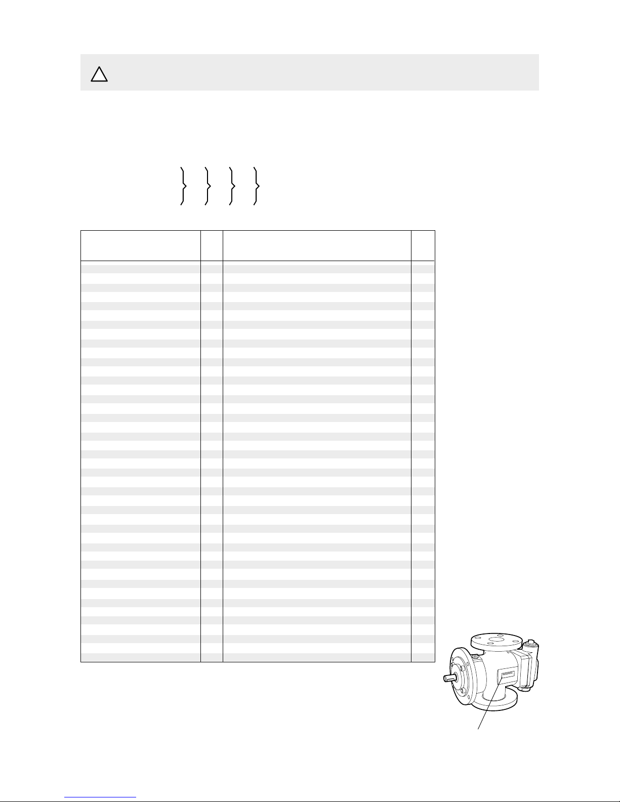
List of components
For more information about the pumps identification code, technical data and performance we refer to the
ACG/UCG Product description. Fore more information about the pumps installation, Start-up and trouble
shooting we refer to the IMO Installation and Start-up instruction for low pressure pumps.
Explanations:
G011: Rotor set
CCW-rotation option
G012: Rotor set
CW-rotation (std)
G050: Shaft seal
G053: Minor kit
(G050 + G057) + 122
G054: Major kit consisting
of: G053+G012 (G011)
G057: Joint kit
G070: Valve element
ACG Pump with DIN
flanges
UCG Pump with ANSI
flanges
A101: CCW
A327: With Tuning
A385: CCW and Tuning
Name plate of the pump
IMO AB
ACG2 ' IMO AB
N
T
VBF
E
P
G
!
Notes:
1) Excluded in xxxG
2) Excluded in xxxE
3) Valid for xxxE
4) Valid for pump option
A327
5) Included in item 1020
or 1010
6) Included in item 5010
7) Only sold as G070
Page 3
3
ACG 0621GB
October 2002
IMO AB, Telephone: + 46 8 50 622 800, Telefax: + 46 8 645 15 09
E-mail: info@imo.se
ACG3 © IMO AB
473
537
537A
506
401
556
480
551
453
462
462A
462
537
537A
473A
1010
201
608A
601
602
605
608
612
615
614
453
480
1020
202
113
113
509
359
359A
514
202
124A
124
122 120
451
5010
453
462
462A
462
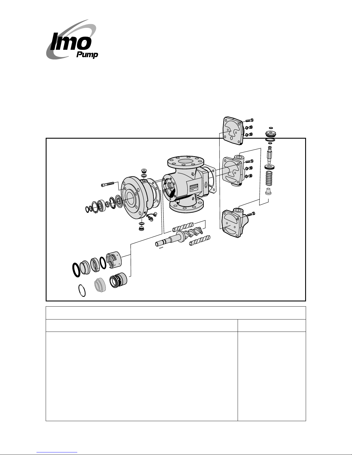
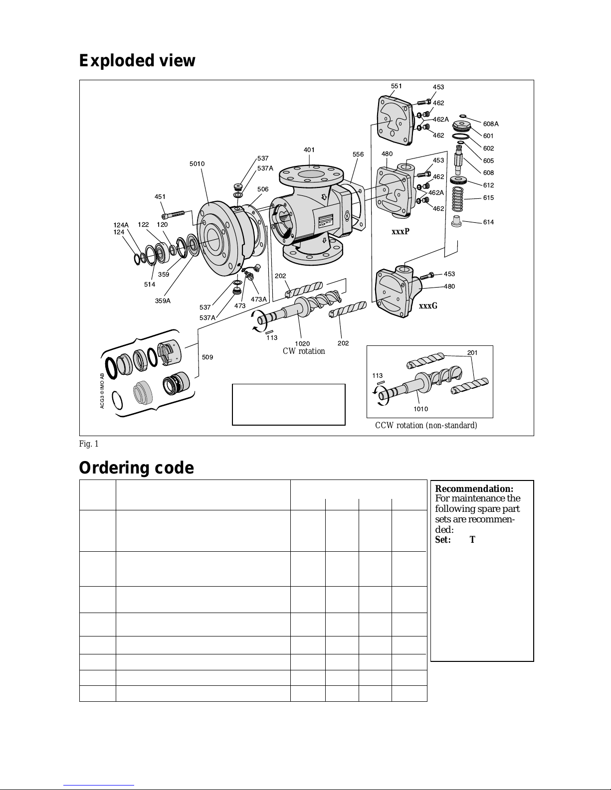
Fig. 1
Exploded view
CCW rotation (non-standard)
xxxP
xxxG
CW rotation
Ordering code
Recommendation:
For maintenance the
following spare part
sets are recommended:
Set: To be used:
G057 Joint kit
For dismantling of
the pump
G053 Minor kit
For service
G054 Major kit
For repair after
damage or greater
wear.
Pos Spare parts sets Part numbers, sizes
No 045 052 060 070
Rotor set CW-rotation (std):
G012 Normal lead - pump version N7 178913 179507 179515 179523
" Low lead - pump version K7 187542 187559 187567 187575
Rotor set CCW-rotation (non-std):
G011 Normal lead - version N7 186478 186486 186494 186502
Low lead - version K7 189641 189642 189643 189644
G050 Complete shaft seal - version code xVxx 190335 190336 190338 190340
” ” - version code xTxx 174094 174102 174110 174128
G053 Minor kit - version code xVxx 191241 191243 191245 191247
” ” - version code xTxx 191242 191244 191246 191248
G054 Major kit=G012(G011)+G053 - - - G057 Joint kit 191237 191238 191239 191240
G070 Valve element - version code xxxP/G 191250 191250 191251 191251
122 Ballbearing 078576 077461 191181 191182
Details in pump option A327
See the sectional view p. 6
Fig. 2
Version xTxx
Ordering example:
For IMO-pump ACG 045N7
NVBP, serial number 456789
Shaft seal
pos G050 p/n 190335
Ballbearing
pos 122 p/n 078576
xxxE
ACG/UCG xxBE/BP/BG
Version xVxx
Page 4
4 ACG 0621GB
October 2002
IMO AB, Telephone: + 46 8 50 622 800, Telefax: + 46 8 645 15 09
E-mail: info@imo.se
Service intervals
The intervals for inspection and replacement of wear
parts vary greatly with the properties of the pumped
liquid and can only be determined by experience.
All internal parts of the ACG-pump are lubricated
by the pumped liquid. Pumping liquid which
contains abrasive materials, or liquid that is corrosive, will significantly reduce service life
and call for shorter service intervals.
Wear in the pump may be indicated by:
• Vibration
• Noise
• Loss of capacity
• Reduction in flow/pressure
• Leakage
In installations where unplanned shut downs must
be avoided, it is advisable to have a complete pump
available for replacement, should any malfunction
occur. Furthermore we recommend planned inspection and overhaul at regular intervals, not exceeding
3 years.
It is recommended always to have the spares included in minor spare part kit available.
Service for ball bearing
The ACG-pump is fitted with an external grease
lubricated ball bearing.
When delivered from IMO AB, the ball bearings in
pump version xVxx are filled with grease of type B.
For version xTxx, type C is used.
Whenever the ball bearing is removed, it is recommended to exchange it for a new one.
Fit the new ball bearing properly greased and
regrease it after one hour of running, while the
pump is operating.
Inspection of shaft seal
As the seal faces of a mechanical shaft seal are
lubricated by the fluid a certain leakage will always
be present. Ten drops per hour can be considered as
acceptable.
An external visual inspection of the pump is advisable at least every two days to assure that the shaft
seal is not leaking too much.
Excessively leaking shaft seals should be changed
without delay, as the leakage normally will grow
worse and cause additional damage.
Follow the instructions in the dismantling/reassembly session.
When working with a shaft seal, cleanliness is of
utmost importance. Avoid touching the seal faces. If
necessary, the seal faces should be cleaned immediately prior to assembly, using a dustfree cloth and
clean solvent.
Never use grease on the seal faces.
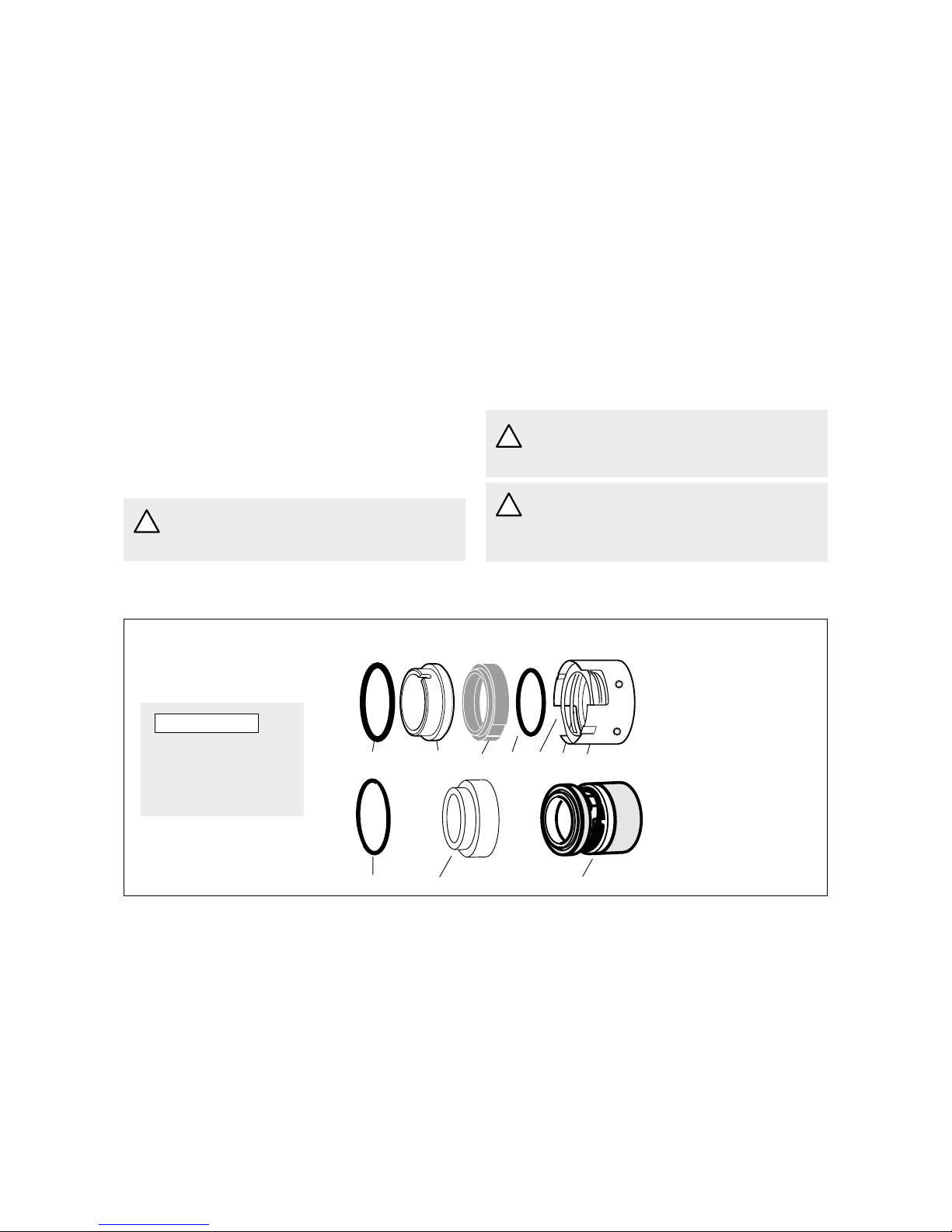
Shaft seal-assembly drawing
Shaft seal G050 (pos 509)
Version code xVxx
Version code xTxx
S2 S1 S5
S2 S1 S4 S6 S9 S7 S5
S1 Seat
S2 O-ring
S4 Seal ring
S5 Seal ring carrier
S6 O-ring
S7 Spring
S9 Stop washer
S1 Seat
S2 O-ring
S5 Bellows unit
Fig. 3
ATTENTION
Be careful to mount
these parts in right
order and in right
direction.
If the pumps operating temperature exceeds
60°C let the pump cool off before any
service, maintenance or dismantling work is
commenced to avoid burn injury.
All work carried out on the pump has to be
performed in such a manner that risks for
personal injury are observed!
Use an appropriate type of grease, as per table and a
grease gun suitable for grease nipple (pos 473)
according to DIN 71 412 (ISO 6392).
On vertical mounted units the greasing intervals are
reduced to half.
Installed in dusty or dirty premises or in a corrosive
environment it should be lubricated at more frequent intervals.
If using others than these recommended greases
check if it is possible to mix them with each other,
otherwise clean before using a new grease.
Connecting and disconnecting of electric
cables must be done only by personnel
authorized to do such work.
ACG8 ' IMO AB
!
!
!
Page 5

5
ACG 0621GB
October 2002
IMO AB, Telephone: + 46 8 50 622 800, Telefax: + 46 8 645 15 09
E-mail: info@imo.se
Useful tools
A
CG7 © IMO AB
Slide calliper
Puller
Mounting sleeve dimensions
Pump size D d L Part No
ACG/UCG 045 ø 25.0 ø 21.0 100 188887
ACG/UCG 052 ø 31.0 ø 26.0 100 188888
ACG/UCG 060 ø 35.0 ø 31.0 100 188889
ACG/UCG 070 ø 42.0 ø 36.0 100 188890
Fine
emery
Oil can Grease
Mounting
sleeve
2 pcs of
screw
driver
Plastic
mallet
Pair of
pliers
Fig. 4
Lubricating intervals in working hours
Temp Pump sizes 045 and 052 Pump sizes 060 and 070
max Grease Speed, r/min Speed, r/min
°C type 3500* 2900 1750 1450 1150 950 3500* 2900 1750 1450 1150 950
70 A 8500 10000 10000 10000 10000 10000 7500 8500 10000 10000 10000 10000
90 A 3350 3950 5350 5950 6350 7500 2950 3350 4750 5150 5950 6750
110 B 2650 3150 4250 4700 5000 5950 2350 2650 3750 4100 4700 5350
130 B 1050 1250 1650 1850 2000 2350 900 1050 1500 1600 1850 2100
155 C 650 750 1050 1150 1250 1500 600 650 950 1000 1150 1300
*) at rotation speed > 3 500 r/min special instructions are given by IMO AB.
Recommended greases (the availability of the greases can differ locally):
Type A: BP Energrease LS 3, Esso Beacon 2, Mobilgrease HP 222, Shell Alvania G3, Texaco Multifak EP2, SKF LGMT2,
Q8 REMBRANDT EP2, CASTROL APS2, ELF ROLEXA 3, TOTAL MULTIS TIR EP3, FINA MARSON L3.
Type B: BP Energrease LC2, CHEVRON SRI GREASE 2, Esso Unirex N3, Mobilith SHC220, SHELL RETINAX LX,
SHELL Albida LX, VAL-PLEX EP GREASE, Texaco Hytex EP2, SKF LGHQ 3, Q8 RUBENS, CASTROL LMX,
INDUSTRIAL GREASE HEAVY, TOTAL MULTIS THT2, FINA PLUTON L2.
Type C: Mobilith SHC 460
Before any maintenance work, ensure
that the driver is deenergized and the
pump hydraulically isolated.
!
!
!
Oil leakage may make the floor slippery
and cause personal injury.
When handling liquids that may harm
skin use gloves and/or protective clothing.
!
!
Pump size 045 052 060 070
Grease amount (g) 4 6 7 9
d
D
GREASE
L
Inspection of rotors
If an indication of a worn pump is noticed (see service
intervals above), a brief inspection of the idler rotors
is recommended.
A quick inspection of the idler rotors can be made
simply by removing the rear cover or valve cover.
Note that the driver must be deenergized and the
pump hydraulically isolated before the rear cover is
removed. Provisions to handle the fluid are to be
made. If a more thorough investigation is needed,
proceed as under ”Dismantling”.
Internal clearances in the pump, which are vital for its
proper function, may have been affected by wear.
Acceptable wear can be determined only by experience of the actual application. As a rule of thumb the
following max clearance values may apply:
• Between rotor and bores or bushings: 0.2 mm
• Between rotor flanks: 0.4 mm
For light duties (low pressure, medium viscosity)
even bigger clearances may be acceptable but for low
visc./high pressure duties the limit will be lower.
Also check if there are major scratches on these parts.
When handling liquids which may involve
fire hazards appropriate precautions to
avoid danger are to be taken.
In case of failure for a system with elevated
pressure, fluid jets may cause injury and/or
damage.
Allen
keys
d
D
L
Mounting kit (M8) Mounting sleeve
Page 6

6 ACG 0621GB
October 2002
IMO AB, Telephone: + 46 8 50 622 800, Telefax: + 46 8 645 15 09
E-mail: info@imo.se
Sectional view
Fig. 5
Version xxxE
Version xxxG
Version xxBP
424A
424
437
429
Option A327
Page 7

7
ACG 0621GB
October 2002
IMO AB, Telephone: + 46 8 50 622 800, Telefax: + 46 8 645 15 09
E-mail: info@imo.se
ACG14 ' IMO AB
Dismantling
• Note the axial position of the shaft coupling.
• Release the stop screw.
A. B.
C. D.
ACG11 ' IMO AB
• Remove the key
113.
• Remove the shaft
coupling.
F.E.
451
• Remove the screws 451.
124
124A
514
ACG12 ' IMO AB
ACG13 ' IMO AB
• Remove the retaining rings 124 and 514.
• Remove the support ring 124A.
Fig. 8 Fig. 9
Fig. 7Fig. 6
Fig. 11
Fig. 10
ACG10 © IMO AB
• Turn the
electricity OFF.
• Close the valves.
• Remove the pump
from the system.
ATTENTION
Use appropriate vessels to collect oil spill-
age when removing and opening the pump.
ACG9 © IMO AB
113
Page 8

8 ACG 0621GB
October 2002
IMO AB, Telephone: + 46 8 50 622 800, Telefax: + 46 8 645 15 09
E-mail: info@imo.se
ACG17 © IMO AB
O AB
J–xTxx.
K.
Shaft seal
Version xTxx
Fig. 16
S4
S6
S5
Fig. 17
• Take out the
idler rotors.
• Clean all parts
that are going
to be used
again.
ACG20 © IMO AB
202
• Unscrew the
seal ring
carrier S5
screws and
take off the
seal ring
carrier S5
together with
the seal ring S4
and the o-ring
S6.
ACG18 © IMO AB
ACG15 © IMO AB
122
120
359
359A
Fig. 12
Fig. 13
G. H.
5010
• Push out the ball
bearing 122 together
with the distance
sleeve 120. If there is
tight fit use a mounting sleeve and a
mallet.
• Remove the distance
washer 359 and the
support ring 359A.
• Remove the
front cover
5010 with a
puller.
I.
J–xVxx.
Fig. 15
Fig. 14
• Turn the front cover 5010 upside down.
• Push out the seat from the front cover 5010.
• Remove the o-ring S2.
• Remove the gasket 506.
• Pull the power rotor 1020 out of the pump
body and place it into the jaws of a jaw vice
with soft jaws or a column drilling machine.
• Push with two drivers as shown on the
sketch, to remove the shaft seal.
S1
S2
506
5010
S5
S5
1020
No tools
from this
side
Shaft seal
Version xVxx
ACG16 ' IMO AB
5010
!
The sealing
surfaces of the
shaft seat
should not be
touched with
the fingers.
Mounting
sleeve
Page 9

9
ACG 0621GB
October 2002
IMO AB, Telephone: + 46 8 50 622 800, Telefax: + 46 8 645 15 09
E-mail: info@imo.se
ACG22 ' IMO AB
S4
S5
Balance
piston
• Lubricate the
idler rotors and
fit them into the
pump.
Lubrication
groove turned
downwards.
202
A.
Fig. 18
Fig. 20
B–xTxx.
Version xTxx
Reassembly
• Open a package
with a new shaft
seal 509 version
xTxx.
• Place the seal ring
carrier S5 on the
shaft of the power
rotor 1020 flush
against the balance piston and
lock it with its
stop screws. Fit
the o-ring S6 and
the seal ring S4.
ACG21 © IMO AB
S6
ACG23 © IMO AB
• Carefully place the
power rotor 1020
into the jaw vice
with soft jaws.
• Lubricate all
surfaces of the
power rotor 1020.
• Open a package
with a new sealing
509, version xVxx.
• Place the bellows
unit S5 on the shaft
of the power rotor
and press it down
against the balance
piston (106) (See
fig. 5).
S5
B–xVxx.
Version xVxx
1020
Fig. 19
C.
Fig. 21
• Lubricate the Oring S2 and the
recess of the front
cover 5010.
• Clean the sealing
faces and fit the
seat S1 into the
front cover 5010.
Mind the position
of the retaining
pin if applicable.
S1
S2
ACG24 © IMO AB
5010
D.
• Lubricate the balance piston 106 with a thick oil (ISO VG 460).
• Fit the front cover onto the power rotor 1020 untill it rests on
the bellows unit S5.
• Fit the support ring 359A and the distance washer 359 into the
front cover. Mind the position of the distance washer 359.
• Fit the distance sleeve 120 into the front cover 5010.
• Fill the ball bearing with appropriate grease. See page 5 for
grease selection.
• Fit the ball bearing 122 onto the shaft.
359
359A
5010
Grease
120
1020
122
Mounting kit
106
Fig. 22
ATTENTION
The open side of the bearing towards the cover.
• Fit the mounting sleeve and push the bearing to
its final position in the front cover. To do this
some force is required. Use Your column drilling
machine or mounting kit (see fig 4).
!
Do not use a hammer etc. as this might
damage the shaft seal and ball bearing.
Page 10

10 ACG 0621GB
October 2002
IMO AB, Telephone: + 46 8 50 622 800, Telefax: + 46 8 645 15 09
E-mail: info@imo.se
F.
• Fit the key back in position, see fig. 9.
• Fit the shaft coupling back into place (see fig. 7
and 8) with the same methode used when
fitting the ball bearing.
Fig. 24
!
Fig. 25
G.
• Remove the plug 537 and washer 537A.
• Hold the rotor unit horizontally with the
bore for 537 upwards. Carefully fill the
space completely with thin oil
(f. ex. ISO VG 46).
• When the oil is flooding, reassemble the
above parts in reverse order.
• Slowly turn the shaft a few turns to make
sure it moves freely (a certain resistance
from the shaft seal is normal but it must be
the same during the turns).
• Fit the support ring 124A and the retaining ring 124 on the shaft.
• Fit the retaining ring 514 back in place.
26 ' IMO AB
124
124A
514
E.
Fig. 23
5010
1020
537
537A
Do not use a hammer etc. as this might
damage the shaft seal and ball bearing.
Page 11

11
ACG 0621GB
October 2002
IMO AB, Telephone: + 46 8 50 622 800, Telefax: + 46 8 645 15 09
E-mail: info@imo.se
ACG29 ' IMO AB
H.
Fig. 26
Fig. 28
Pressure relief valve
Replacement of O-ring 605
• To avoid changing the setting of the valve, use an
Allen key to prevent spindle 608 to turn.
Unscrew cover 601 and pull up unit 601/608.
• Remove retaining ring 608A and pull the spindle
608 out of cover 601. Replace O-ring 605 and
assemble the unit 601/608 in reverse order.
Replace retaining ring 608A if necessary and
washer 602.
• Fit the unit 601/608 in the valve. Make sure the
608 enters the set screw 612 and use the Allen
key to prevent 608 to turn when cover 601 is
tightened.
Replacement of Valve Element G070
• Release the spring tension by turning the spindle
608 CCW with an Allen key. Use the Allen key to
prevent spindle 608 to turn and unscrew cover
601 but do not remove it yet.
• Remove the set screw 612 by turning the spindle
608 CCW. Pull out the valve piston/spring unit
614/615.
• Fit the valve element in reverse order with a new
washer 602. Turn the spindle 608 CW until the
set screw leave enough room for cover 601. Use
the Allen key to prevent 608 to turn further when
cover 601 is tightened.
• Adjust the valve setting according to the "Installation and Start-up Instruction for IMO Low
pressure pumps".
451
5010
1020
506
• Place the gasket 506 on the pump body 401.
• Lubricate the power rotor 1020 and fit the
front cover 5010 together with the rotor set
into the pump body. Mind the position of
the tension pin 545.
• Fit the screws 451 and tighten them crosswise.
Version G
Version P
ACG30 ' IMO AB
480
608A
601
602
605
608
612
615
614
453
480
453
462
462A
462
401
Fig. 27
I.
• Put the pump back into the system and
proceed according to instructions under
”Start-up” in the installation manual.
Page 12

IMO AB: P. O. Box 42090, SE 126 14 Stockholm, Sweden
Telephone: +46 8 50 622 800, Telefax: +46 8 645 1509
www.imo.se
 Loading...