

Page 1
ACF5 0601.01 GB
ACF5
Maintenance & Service Instruction
Screw pump
Page 2

ACF5 0601.01 GB
www.imo.se
2
Indentification of safety instructions
Non complience of safety instruc-
tions identied by the following
symbol could aect safety for
persons
Safety instructions where
electrical safety is invol-
ved are identied by:
Safety instructions which shall be considered
for reasons of safe operation of the pump
or pump unit and/or protection of the
pump or pump unit itself are marked
by the sign:
cm
;
Introduction
A screw pump from IMO is a quality product that is designed for a long problem free operation in tough environments. As all other mechanical products they do however requires a certain grade of maintenance and service in
order to guarantee a faultless and economic favourable operation.
A recommendation is to go through the pump each 5 year in order to replace wear details such as ball bearings,
the mechanical seal and certain gaskets and o-rings. A relatively small review of a screw pump from IMO means
that the pump in most of the cases will be in a condition “as new” and therefore give the operator another long and
problem free operation.
Page 3

ACF5 0601.01 GB
www.imo.se
3
Contents
Introduction .......................................................................................................................................................................... 2
List of components ............................................................................................................................................................... 4
Recommended Spare Parts Kits ......................................................................................................................................... 5
Service intervals ................................................................................................................................................................... 6
Inspection of rotors .............................................................................................................................................................. 6
Inspection of sha seal ........................................................................................................................................................ 6
Warranty maers ................................................................................................................................................................. 6
Precautions prior to starting maintenance on the pump .............................................................................................. 6
Dismantling and reassembling the pump 7
List of tools necessary for dismantling and reassembly ................................................................................................ 7
Sectional View ...................................................................................................................................................................... 7
Dismantling 8
Reassembly 1
2
Installation and Start-up Instruction 15
Installation 16
Transport and storage ....................................................................................................................................................... 16
Liing of pump .................................................................................................................................................................. 16
Allignment and sha couplings ...................................................................................................................................... 16
Strainer ................................................................................................................................................................................ 17
Pipe connections ................................................................................................................................................................ 18
Suction line ......................................................................................................................................................................... 18
Discharge line ..................................................................................................................................................................... 18
Deaeration ........................................................................................................................................................................... 18
Liquid trap .......................................................................................................................................................................... 18
Gauges ................................................................................................................................................................................. 19
Pressure relief valve .......................................................................................................................................................... 19
Start-up 20
Before starting: ................................................................................................................................................................... 20
Direction of rotation .......................................................................................................................................................... 20
Safety precautions before starting .................................................................................................................................. 20
Starting ................................................................................................................................................................................ 20
Seing the pressure relief valve ...................................................................................................................................... 21
Adjusting the tuning ......................................................................................................................................................... 21
Seing of tuning of the ACF: ............................................................................................................................................ 21
Trouble shooting 22
Page 4

ACF5 0601.01 GB
www.imo.se
4
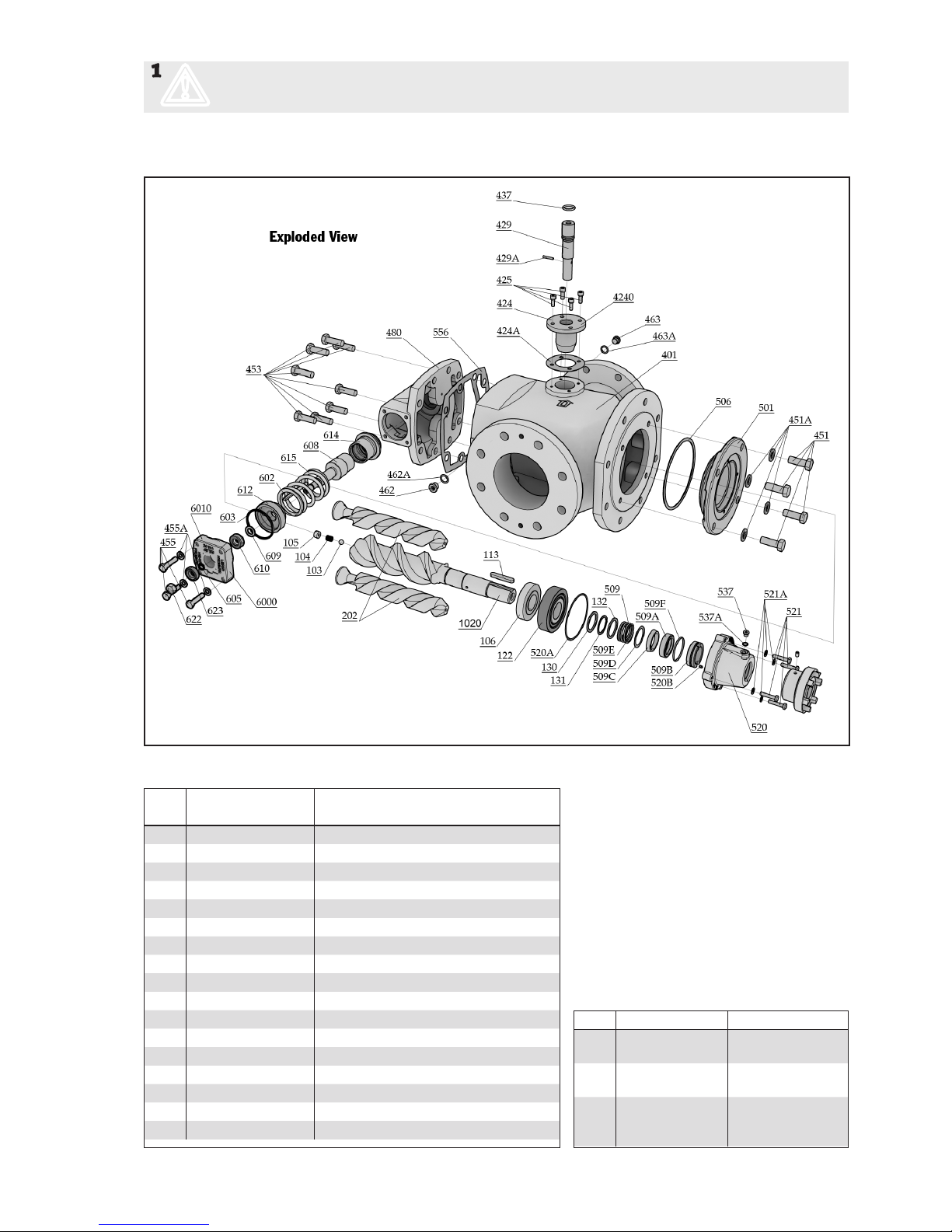
Explanations:
ACF: Pump with
DIN anges
CW: Clockwise
rotation
CCW: Counter clock
-
wise rotation
G011: Rotor set CCW
rotation
G012: Rotorset CW
rotation
G050: Compl sha
seal
G053: Minor kit
(G050+G057)
G054: Major kit
G057: Joint kit
G070: Valve element
Included components in Spare part sets
Pos Part Denomination Qty G011 G012 G050 G053 G054 G057 G070
1010 Complete power rotor (CCW-rot.) 1 x x
1020 Complete power rotor (CW-rot.) 1 x x
(103) Ball 1 (x) (x) (x)
(104) Spring 1 (x) (x) (x)
(105) Hole screw 1 (x) (x) (x)
(106) Balancing piston 1 (x) (x) (x)
113 Key 1 x x x
122 Ball bearing 1 x x x
130 Support ring 1 x x x
131 Retaining ring 1 x x x
132 Support ring 1 x x x
201 Idler rotor (CCW-rotation) 2 x x
202 Idler rotor (CW-rotation) 2 x x
401 Pump body 1
4240 Tuning element 1
(424) Cover 1
(424A) Gasket 1 x x x
(425) Screw 4
(429) Guiding screw 1
(429A) Tenison pin 1
(430) Piston 1 (Valid for sizes 100-125) 1
(432) Tenison pin (Valid for sizes 100-125) 1
(437) O-ring 1 x x x
451 Screw 4
451A Washer 4
453 Screw 8
455 Screw 4
455A Washer 4
462 Plug 1
462A Washer 1 x x x
463 Plug 1
463A Washer 1 x x x
480 Valve housing 1
501 Front cover 1
506 O-ring 1 x x x
509 Mechnical seal 1 x x x
(509A) Rotating seal ring 1 (x) (x) (x)
(509B) Seat 1 (x) (x) (x)
(509C) Rubber ring 1 (x) (x) (x)
(509D) Washer 1 (x) (x) (x)
(509E) Spring 1 (x) (x) (x)
(509F) O-ring 1 (x) (x) (x) x
520 Compl. cover 1
520A O-ring 1 x x x
(520B) Tension pin 1
521 Screw 4
521A Washer 1
(537) Plug 1
(537A) Washer 1 x x x
556 Gasket 1 x (x) x
6000 Valve cartridge 1 x
(6010) Compl. valve cover 1 (x)
(602) Pin 1 (x)
(603) O-ring 1 x x x (x) (x)
(605) O-ring 1 x x x (x) (x)
(608) Valve spindle 1 (x)
(609) Washer 1 (x)
(610) Ball bearing 1 x x (x) (x)
(612) Regulating nut 1 (x)
(614) Valve piston 1 (x)
(615) Spring 1 (x)
(622) Nut 1 (x)
(623) Ball bearing 1 x x (x) (x)
List of components
Valid for all ACF Generation 5 pumps with leads and sizes: 080, 090, 100 K5/N5 & 110, 125 L5/N5.
With version codes: IVBP & NVBP. Also valid with options A020, A078, A101.
Page 5
ACF5 0601.01 GB
www.imo.se
5
1
m
Before commencing any work, read this instrucion carefully! Failure to comply with these instrutions
may cause damage and personal injury!
For more information about the pumps identication code, technical data and performance we refer to the ACF
Product description.
Pump size
Pos 080 090 100 110 125
G011 Rotor set N-lead 192966 192968 192970 192972 192974
CCW K-lead 192967 192969 192971
L-lead 192973 192975
G012 Rotor set N-lead 192785 192958 192960 192962 192964
CW CW K-lead 192786 192959 192961
L-lead 192963 192965
G050 Sha seal xVxx 192525 192525 192526 192526 192526
G053 Minor kit xVxx 192987 192987 192988 192988 192989
G057 Joint kit xVxx 192990 192990 192991 192991 192992
G070 Valve xxxP 192553 192553 192554 192554 192555
G099 Complete IEC 132 192993 192997
sha IEC 160 192994 192998 193002 193002 193002
coupling IEC 180 192995 192995 193003 193003 193003
IEC 200 192996 192996 193004 193004 193004
IEC 225 193001 193005 193005 193005
IEC 250 193006 193006 193006
IEC 280 193007 193007 193007
Kit Contents To be used for
G057 Gaskets, o-rings,
ball bearing, etc
Dismantling of
the pump
G053 G057 + Sha seal
G050
Normal scheduled inspection
G054 G053 + Complete
rotor set
Repair aer major
breakdown or
great wear
Recommended Spare Parts Kits
Every shutdown for service of a plant is
costly. The time for repair should therefore
be limited to a minimum which can be
accomplished by keeping a spare pump.
The changed pump can later be repaired at
a suitable place and can then be used as a
spare pump. For maintenance the following
spare parts kits are recommended:
Ordering Code
Page 6
ACF5 0601.01 GB
www.imo.se
6
Service intervals
The intervals for inspection and replacement of wear
parts vary greatly with the properties of the pumped
liquid and can only be determined by experience. All
internal parts of the ACF-pump are lubricated by the
pumped liquid.
Pumping liquid which contain abrasive materials, or
liquid that is corrosive, will signicantly reduce service
life and call for shorter service intervals.
Wear in the pump will normally show as:
• Vibration
• Noise
• Loss of capacity
• Reduction in ow/pressure
• Leakage
We recommend planned inspection and overhaul at
regular intervals, not exceeding 3 years.
It is recommended to always have the spares included
in minor spare part kit G053 available for a planned
inspection.
Inspection of rotors
To reach the idler rotors in a quicker way than described in the dismantling section, loosen the rear cover
(480) with valve. Screw out the idler rotors backwards.
Internal clearances in the pump, which are vital for its
proper function, may have been aected by wear. Acceptable wear can be determined only by experience of
the actual application. As a rule of thumb the following
max clearance values may apply: Between rotor and
bores: 0.2 mm, Between rotor anks: 0.4 mm For light
duties (low pressure, medium viscosity) even bigger
clearances may be acceptable but for low visc./high
pressure duties the limit will be lower. Also watch if
there are major scratches on these parts.
Inspection of shaft seal
As the seal faces of a mechanical sha seal are lubricated by the uid a certain leakage will always be present.
Ten drops per hour can be considered as acceptable. An
external visual inspection of the pump is advisable at
least every two days to assure that the sha seal is not
leaking too much.
Excessively leaking sha seals should be changed without delay, as the leakage normally will grove worse and
cause additional damage.
Follow the instructions in the dismantling/reassembly
session. When working with a sha seal, cleanliness is
of outmost importance. Avoid touching the seal faces.
If necessary, the seal faces should be cleaned immediately prior to assembly, using a dust free cloth and clean
solvent.
Warranty matters
IMO AB´s warranty obligations covers new pumps for 1
year aer the commissioning of the pump.
Parts that NOT are covered by the warranty are normal
wear details such as the mechanical sha seal, the ball
bearing or the exible coupling.
Precautions prior to starting maintenance on
the pump
2
m
If the pumps operating temperature
exceeds 60°C, let the pump cool o before
any service, maintenance or dismantling
work is commenced to avoid burn injury
3
m
All work carried out on the pump has to be
performed in such a manner that risks for
personal injury are observed!
4
m
When handling liquids that may harm skin,
use gloves and/or protecting clothing!
5
m
When handling liquids which may involve
re hazard appropriate precautions to
avoid danger are to be taken.
6
m
In case of failure for system with elevated
pressure, uid jets may cause injury and/
or damage.
7
m
Oil leakage may make the oor slippery
and cause personal injury.
8
m
Before any maintenance work, ensure that
the driver is deenergized and the pump
hydraulically isolated.
9
c
Connecting and disconnecting of electrical
cables must be done only by personnel
authorized to do such work.
Page 7
ACF5 0601.01 GB
www.imo.se
7
ACF 5 © IMO AB
d
D
GREASE
L
A B C D E F G H I
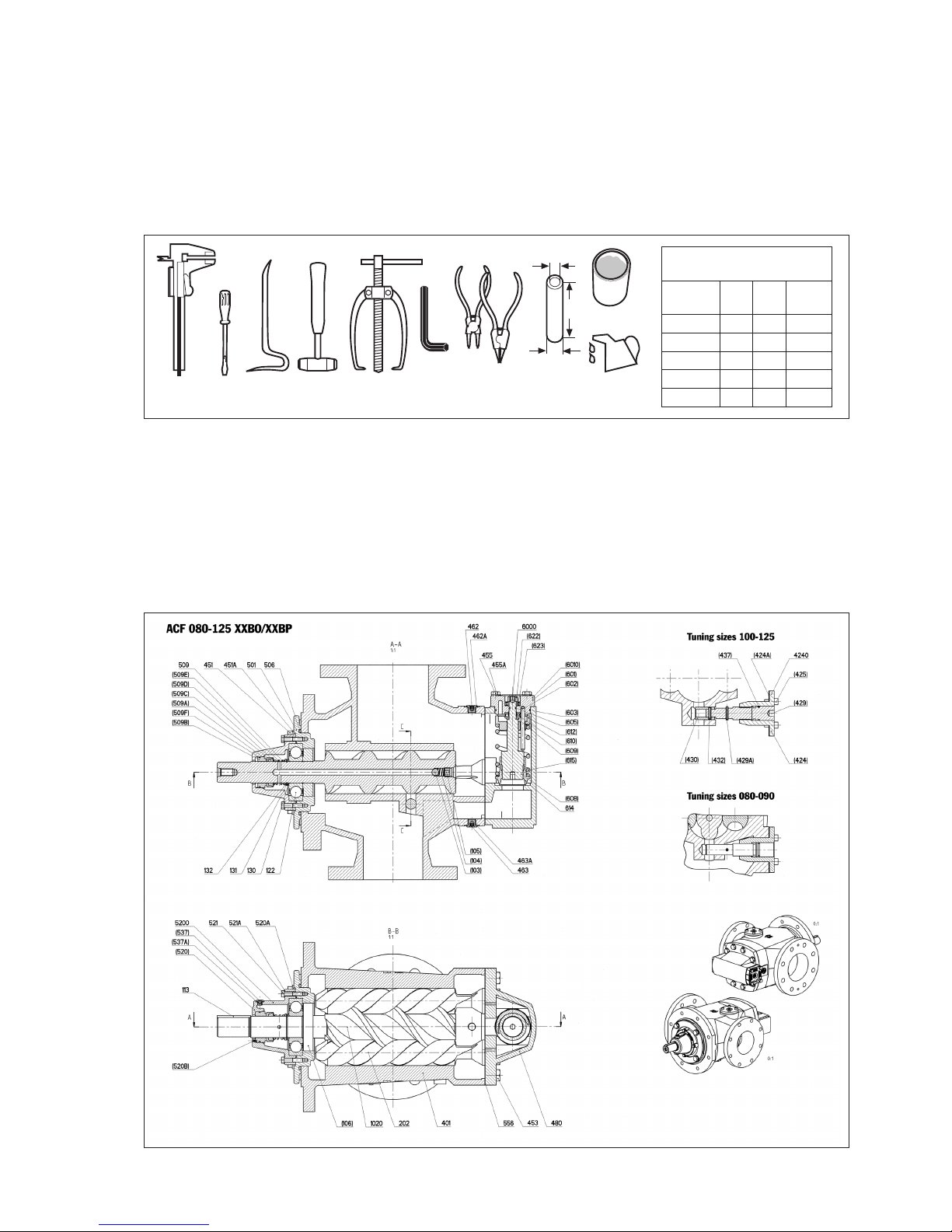
List of tools necessary for dismantling and reassembly
A = Slide calliper
B = Screw driver
D = Crow bar
E = Plastic mallet
F = Puller
G = Allen key
H = Pairs of pliers
I = Mounting sleeve
J = Oil can
Sectional View
Dismantling and reassembling the pump
Mounting sleeve
dimensions (mm)
Pump
size d L D
080 46 155 62 ±3
090 46 155 62 ±3
100 66 180 85 ±4
110 66 180 85 ±4
125 66 180 85 ±4
Page 8
ACF5 0601.01 GB
www.imo.se
8
ACF5 © IMO AB
ON
OFF
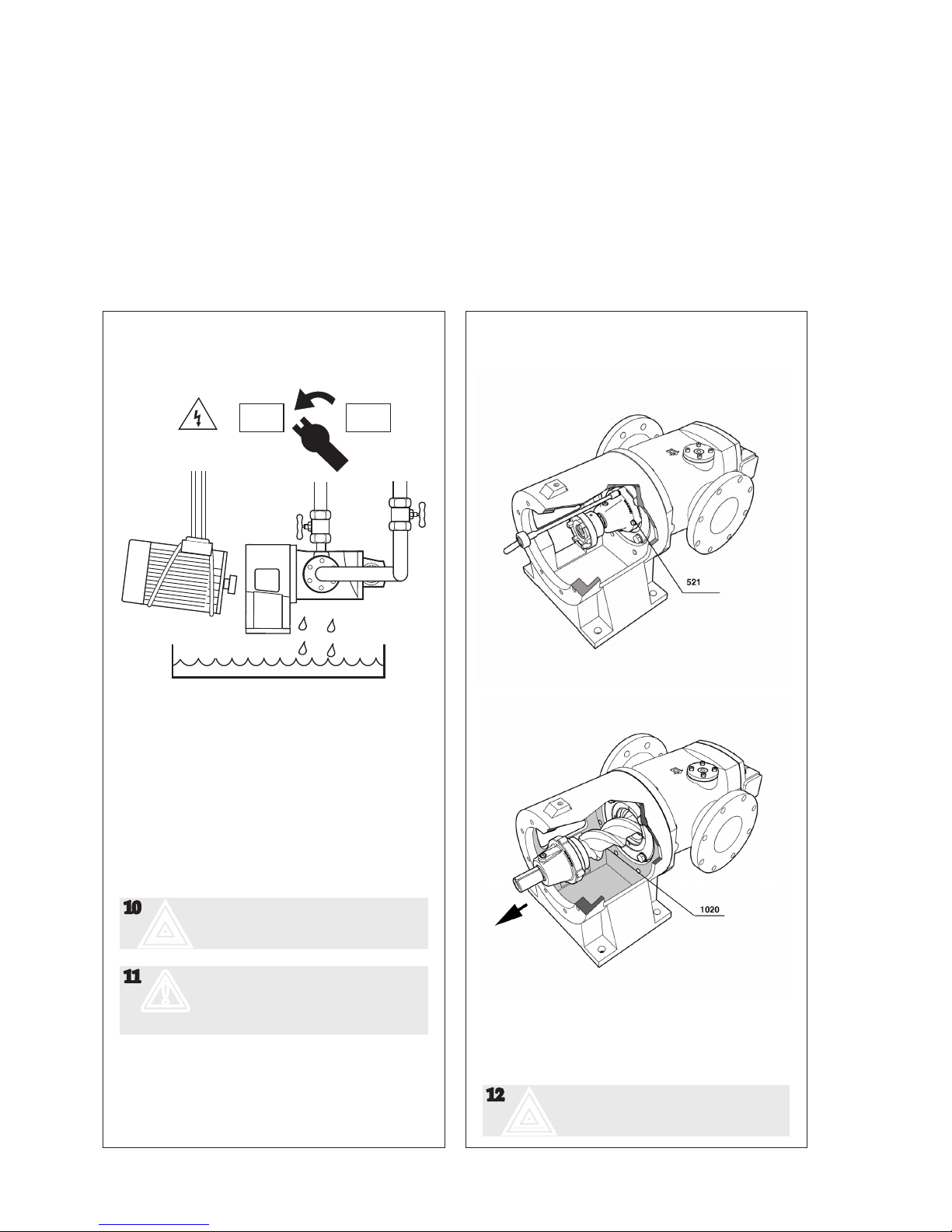
Dismantling
A.
For most installations repair can be done with the
pump in place by removing the motor.
• Turn the electricity OFF.
• Close the valves.
• Disconnect the electric motor.
• For horizontal installation drain the pump by
loosen screws 453 3-4 turns and loosen 480
valve housing.
10
;
Use appropriate vessels to collect oil
spillage when operating the pump
11
m
Pump and/or motor should be lied
with straps securely so that the
centre of gravity is located in order
to avoid tipping
B.
• Loosen and remove screws 521
• Pull out the power rotor 1020 with the help of
coupling half or an eye bolt ed in the power
rotor
12
;
Be careful when the threaded part of
the rotor passes the bore in the cover
Page 9
ACF5 0601.01 GB
www.imo.se
9
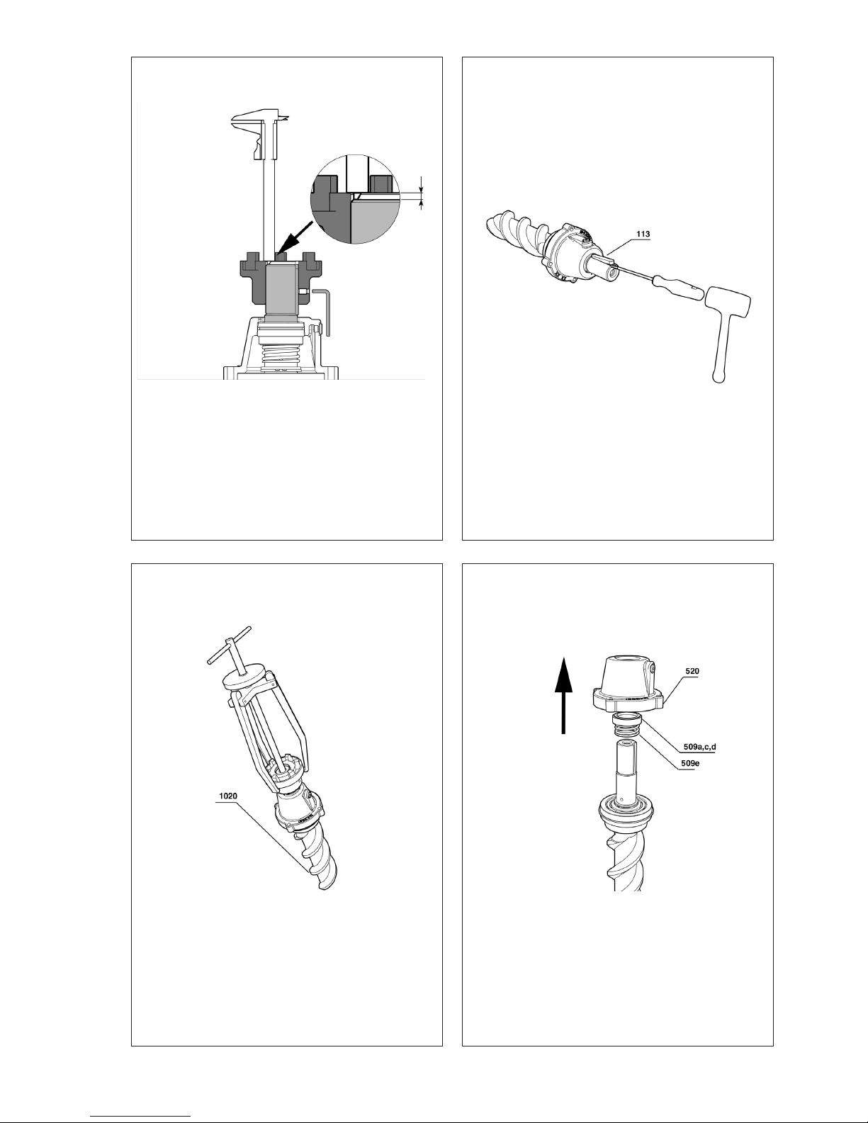
E.
• Remove the key 113
C.
• Note the axial posistion of the coupling half
• Release the stop screw
F.
• Pull the cover 520 upwards
• Carefully slide the rotary sha seal parts 509 a,
c, d, e upwards.
D.
• Remove the coupling half with a puller
Page 10

ACF5 0601.01 GB
www.imo.se
10
G.
• Remove the washer 132.
• Remove the circlip 131 with a plier.
• Remove the washer 130.
I.
• Press down the complete stationary part of the
sha seal 509b & 509f out the end cover 520 by
means of a Teon piece that ts smoothly.
NOTE: The other end of the Teon piece should
t on the opposite side of 509b and is used lager
on when 509b is pressed into the end cover 520
again.
J.
• Loosen the bolts 451 and remove the frontcover
504 with its o-ring 506 from the pump body
401.
H.
• Remove the ball bearing 122 from the rotor
1020 with a three legged puller.
Page 11

ACF5 0601.01 GB
www.imo.se
11
M.
• Remove the cylindrical spring loaded pin 429a
with a suitable puncher.
• Unscrew the tuning piston 429 counter-clock
-
wise from the cover 4420.
K.
• Carefully slide the idle rotors out of the Pump
body.
• Loosen the bolts 425 and pull the complete tun
-
ing device straight upwards.
N.
• Change o-ring 437 on the tuning piston 429
and mount it in 4240 in reverse order.
L.
• Loosen the 4 bolts 455 & 455a in order to pull
out the complete valve insert.
• Reassemble in opposite order.
• Loosen the 8 bolts 453 in order to remove the
back cover 480.
• Reassemble in opposite order.
Page 12

ACF5 0601.01 GB
www.imo.se
12
B.
• Mount the front cover 501 and its o-ring 506 on
the pump body 401 with the 4 screws.
• Lubricate the o-ring 506.
C.
• Mount the ball bearing 122 on the power rotor
1020 with the mounting tool by tightening the
nut.
NOTE: The measurement of this tool varies
depending on the pump size, a measurement
table can be found in the tool description on
page 7.
The tool can also be purchased from IMO AB.
A.
• Lubricate the idler rotors carefully and slide
them into the bores of the pump body.
NOTE: The position of the idler rotors should
be exactly as shown above as it otherwise will
be dicult to mount the power rotor.
Reassembly
Page 13

ACF5 0601.01 GB
www.imo.se
13
F.
• Slide on the rotating parts of the mechanical
sha seal on the power rotor as shown above,
grease the surface thoroughly on the power rotor as this prevents damage to the seals rubber
details when mounting it.
• Lubricate the seal face on the seat 509a with
grease. We recommend grease of ”Graphite”
or”Molybdendisulphite”type.
NOTE: It is verimportant that the mechanical seal
are handled with care and cleanliness is to be
considered as crucial.
D.
• Mount the washers 130 and 132 together with
the circlip 131.
E.
• Complete mechanical sha seal
Page 14

ACF5 0601.01 GB
www.imo.se
14
G.
• Mount the stationary sha seal part 509b with
its o-ring 509f into the end cover 520 by means of
a suitable Teon tool.
• The seal must be mounted so that the slot at the
boom of 509b corresponds with the guiding
pin 520b.
NOTE: The o-ring 509f must be thoroughly
greased as it otherwise easily could be damaged
during the mounting.
H.
• Mount the complete end cover 520 carefully on
the power rotor 1020.
• Remount the sha coupling with a suitable tool.
NOTE: Do NOT mount the coupling half with a
hammer as this will destroy the sha seal.
I.
• Lubricate and t the power rotor 1020 into the
pump by carefully guide it into the idler rotors
”openings”, see g A on page 12.
• Make sure that the de-aeration plug always is
pointing upwards and reconnect the de-aeration
extension pipe.
• Tight the screws 521 crosswise to help the rotor
to reach its nal position.
• Check that the pump sha moves freely.
• Fit the electric motor back to the pump.
• Check the correct seing of sha coupling ac
-
cording to ”Alignment and sha couplings” and
proceed according to instruction under ”Startup” in this manual.
Page 15

ACF5 0601.01 GB
www.imo.se
15
Installation and Start-up Instruction
Valid for ACF 080-125 Generation 5
BEFORE COMMENCING ANY WORK,
READ THIS INSTRUCTION CAREFULLY!
Indentification of safety instructions
Non complience of safety instruc-
tions identied by the following
symbol could aect safety for
persons
Safety instructions where
electrical safety is invol-
ved are identied by:
Safety instructions which shall be considered
for reasons of safe operation of the pump
or pump unit and/or protection of the
pump or pump unit itself are marked
by the sign:
cm
;
Page 16
ACF5 0601.01 GB
www.imo.se
16
max 90°
min 60°
max 90°
min 60°
Fig 1. Liing the pump
Design limitations and technical data for each pump
are found in the Product description. Installation of
IMO AB low pressure pumps does not require special
skills. However, these instructions presume that the
work is carried out by experienced ers!
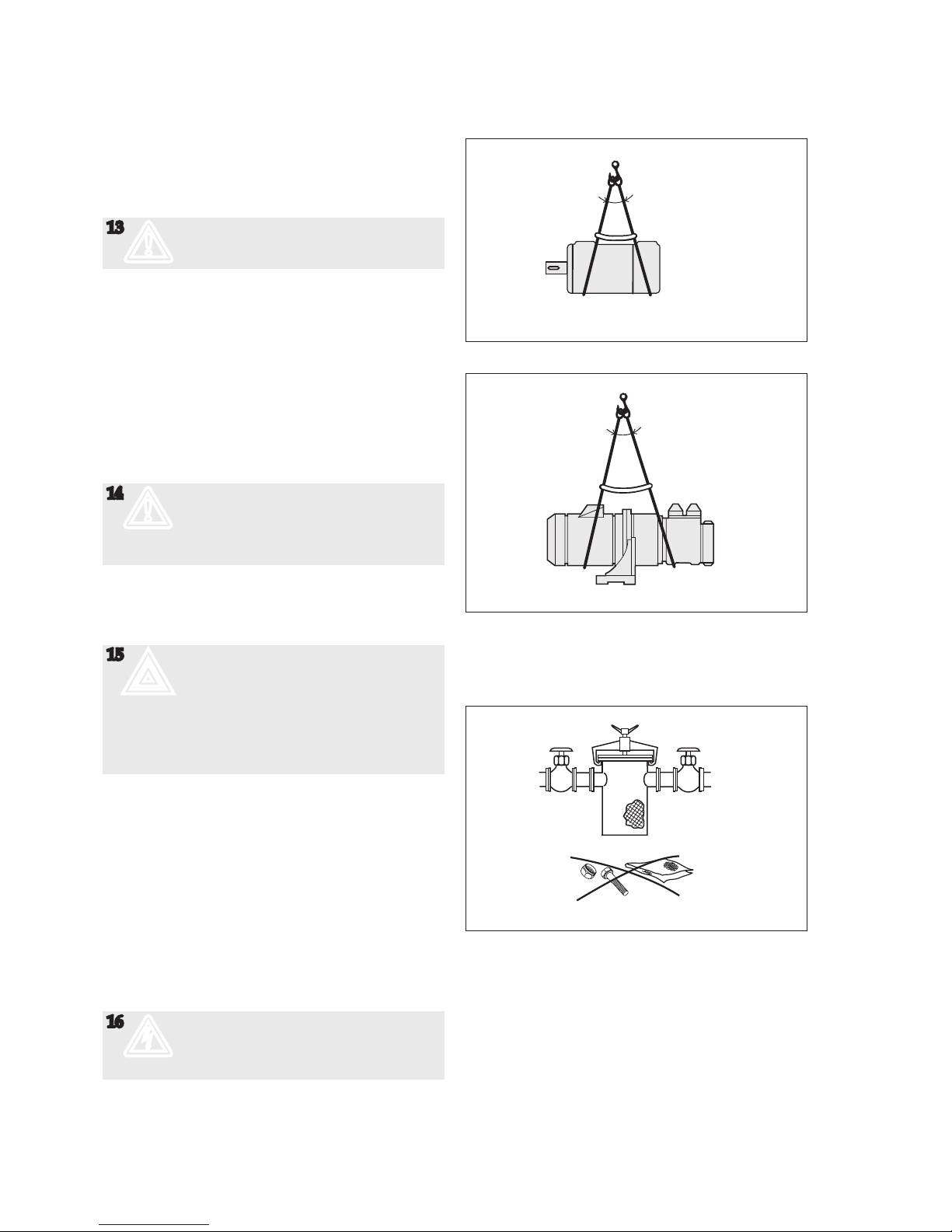
13
m
Failure to comply with these instructions
may cause damage and personal injury
Transport and storage
Always protect the pump against ingress of water and
other impurities. Store the pump in a clean, dry and
warm environment. The pump is delivered with the
internals oiled and with protective covers over the
pipe connections and drain openings. These covers
should remain in place for as long as possible during
the mounting and installation procedure but must be
removed before start up.
Lifting of pump
14
m
All pumps should be lied with straps
securely aached to the pump or pump
unit, so that the center of gravity is located
between the straps in order to avoid
tipping of the pump.
Liing of the complete pump unit with the liing
device aached to the motor, should be avoided as the
motor’s liing provisions may not be able to carry the
combined weight of the pump and motor.
15
;
The installation must be designed
to minimize damage. Should an
operational or functional failure occur.
E.g. precautions should be considered to
collect oil spillage due to a broken pipe or
pump housing, to stop pump operation
if overheating should occur or if the oil
volume is below a minimum tank level.
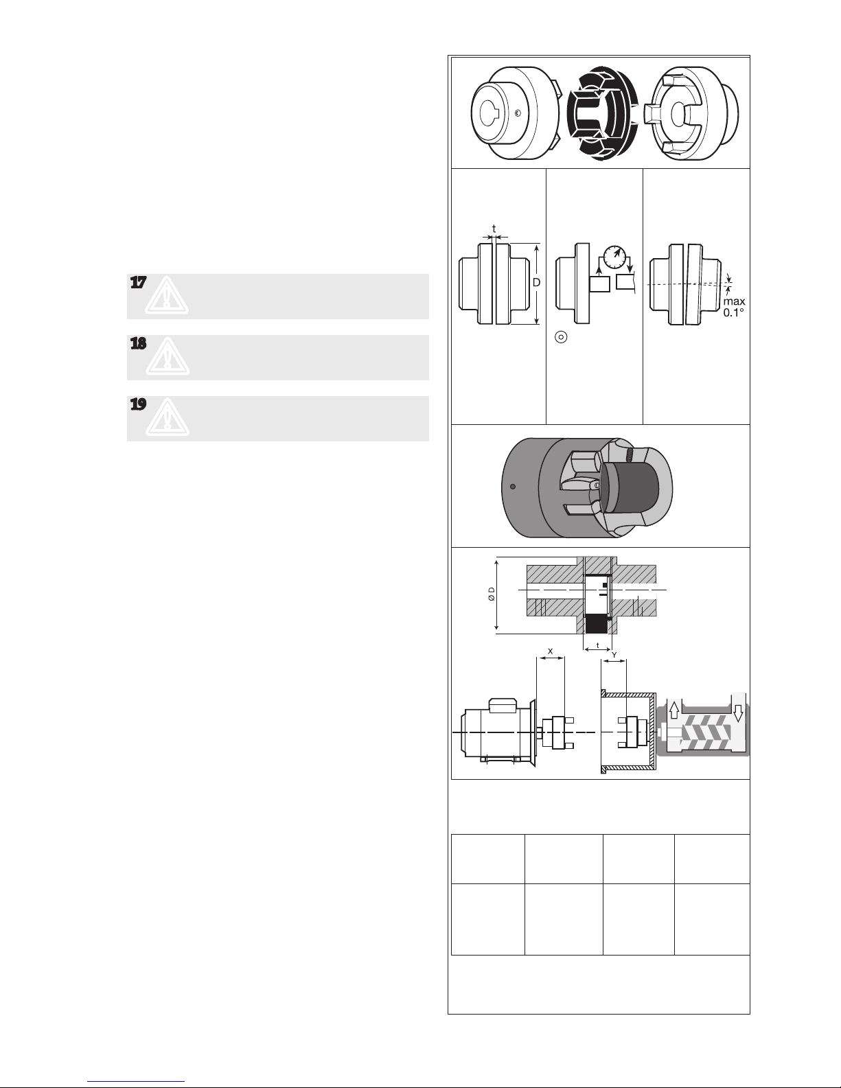
Allignment and shaft couplings
The pump shall be connected to its driver via a exible
sha coupling; they may also be driven via gears or
pulleys as specied in the Product Description, provided that the radial forces are kept within the specied
range. An angular misalignment of 0.1° corresponds to
approximately. 0.2 mm deviation/100 mm. The coupling
and alignment shall be selected not to transmit any axial or radial loads on the sha ends. IMO AB standard
couplings shall have a distance between the coupling
halves as per table, g 4. The coupling halves shall be
secured by lock screws. For other types of couplings,
please refer to respective maker’s manual.
16
c
When ing the sha coupling, do not use
a hammer or similar as this may damage
the ball bearing and sha seal.
Use some kind of press tool.
Fig. 2 Strainer
Installation
Page 17
ACF5 0601.01 GB
www.imo.se
17
Strainer
The pump has to be protected from foreign maers
such as weld slag, pipe scale, etc., that could enter the
pump via the suction line. If the cleanliness of the system cannot be guaranteed, a strainer must be installed
in the inlet pipe near the pump. For practical reasons
a suction strainer with 0.8-2.0 mm mesh openings is
recommended.
The size of the strainer should be selected so that it is
large enough to allow adequate pressure at the pump
inlet. The pressure drop across the strainer should
preferably not exceed 0.1 bar at max. ow rate and normal operating viscosity. A vacuum gauge between the
strainer and the pump inlet is recommended to indicate
when the strainer needs cleaning.
17
m
Oil leakage may make the oor slippery
and cause personal injury
18
m
When handling liquids that may harm
skin, use gloves and/or protective clothing
19
m
When handling liquids which may involve
re hazard, appropriate precautions to
avoid danger are to be taken.
Fig. 4 Distance between coupling halves.
(IMO AB standard coupling)
Outer diameter
of coupling
(D mm)
Distance between
coupling halves
(t mm)
Outer diameter
of coupling
(D mm)
Distance between
coupling halves
(t mm)
A B A B
50 26 2.0 8 148 3.5
67 40 2.5 16 168 3.5
82 55 3.0 18 194 3.5
97 65 3.0 20 214 4.0
112 80 3.5 24 240 4.0
128 95 3.5 26
Fig. 3 Alignment of the IMO AB standard coupling
D4 ø max 0.3 mm
D6 ø max 0.4 mm
E4 ø max 0.4 mm
See table below
An angular
misalignment of
0.1° corresponds to
approx. 0.2 mm
deviation/100 mm.
Angular
alignment
Distance
between
coupling halves
Circular
run-out
A
x = y - t
B
Page 18

ACF5 0601.01 GB
www.imo.se
18
Fig. 7 Deaeration
Pipe connections
The pipe work shall be installed and supported so that
no pipe stresses are transferred to the pump body. The
pipe work should be tight in order to avoid leakage
and inltration of foreign particles and/or air. Shut o
valves should be installed in both suction and discharge pipes, so that the pump can be hydraulically
isolated.
Suction line
The suction pipe should be designed so that the total
pressure drop, measured at the pump inlet ange, does
not exceed the suction capability of the pump. Make a
proper calculation of the suction line including components such as valves, strainer, pipe bends etc. Generally, the pressure drop in the suction line should be as
low as possible, which is achieved if the suction pipe is
short, straight and has a suitable diameter. The velocity in the suction line should be kept in the range 0.5
- 1.2 m/s. For L.O. circulating systems, we recommend
to keep it as low as possible. The suction line must
be equipped with a port that allows lling the pump
before start.
Discharge line
The discharge line should be dimensioned to keep the
velocity in the range 1 - 3 m/s.
Deaeration
In installations with negative suction head, where the
pump might be started against a pressurized system, a
deaeration pipe with an orice (2-3 mm is recommended) has to be installed. The deaeration pipe should be
connected to the outlet pipe’s highest point. This must
also be installed when the pump is used as a stand-by
pump.
Shaft seal drain
The pump should be installed so that any leakage from
the sha seal does not become a hazard. As the sha
seal has to be lubricated a small amount of oil dripping
cannot be avoided. Provisions to collect the leakage
from the sha seal must be made. A drain pipe can
be connected to the drain connection on the pump.
However, when pumping heavy fuel oil or any other
liquid that is likely to become very viscous at ambient
temperature, we recommend that the liquid is allowed
to drop freely from the drain opening.
Liquid trap
In some mounting arrangements the pump may not
retain the liquid at stand still. In such installations the
suction pipe should be arranged so it forms a liquid
trap together with the pump, keeping the pump half
lled with liquid.
Fig. 5 Pipe connections
Fig. 6 Suction Line
Page 19

ACF5 0601.01 GB
www.imo.se
19
Gauges
Gauges for monitoring the pump’s working conditions
are recommended. These gauges should be placed
readable as close to the pumps in- and outlet anges as
possible. The ACF pump is equipped with convenient
connections for measuring the inlet and the outlet pressure by means of pressure gauges.
Pressure relief valve
All systems with screw pumps must be equipped with
a pressure relief valve installed immediately adjacent
to the pump. In the standard versions of IMO AB low
pressure pumps, this pressure relief valve is an integral
part of the pump to protect the system against excess
pressure. When liquid is circulated through the valve
it heats up in proportion to the set pressure level and
the percentage of by-passed liquid. 100% by-pass can
only be tolerated for less than about 3 minutes, 50%
by-pass generally for unlimited periods of time. If more
than 50% recirculation is anticipated, a value specic
to each application should be determined by closely
monitoring the pump body temperature. If the pump is
operating in line with a separate pressure control valve,
the seing of the relief valve should be high enough so
as not to interfere with the control valve. Likewise, if
two pumps are operating in parallel, the seing should
be such that interference between the two valves is
avoided.
Page 20
ACF5 0601.01 GB
www.imo.se
20
ACF
Deaeration plug
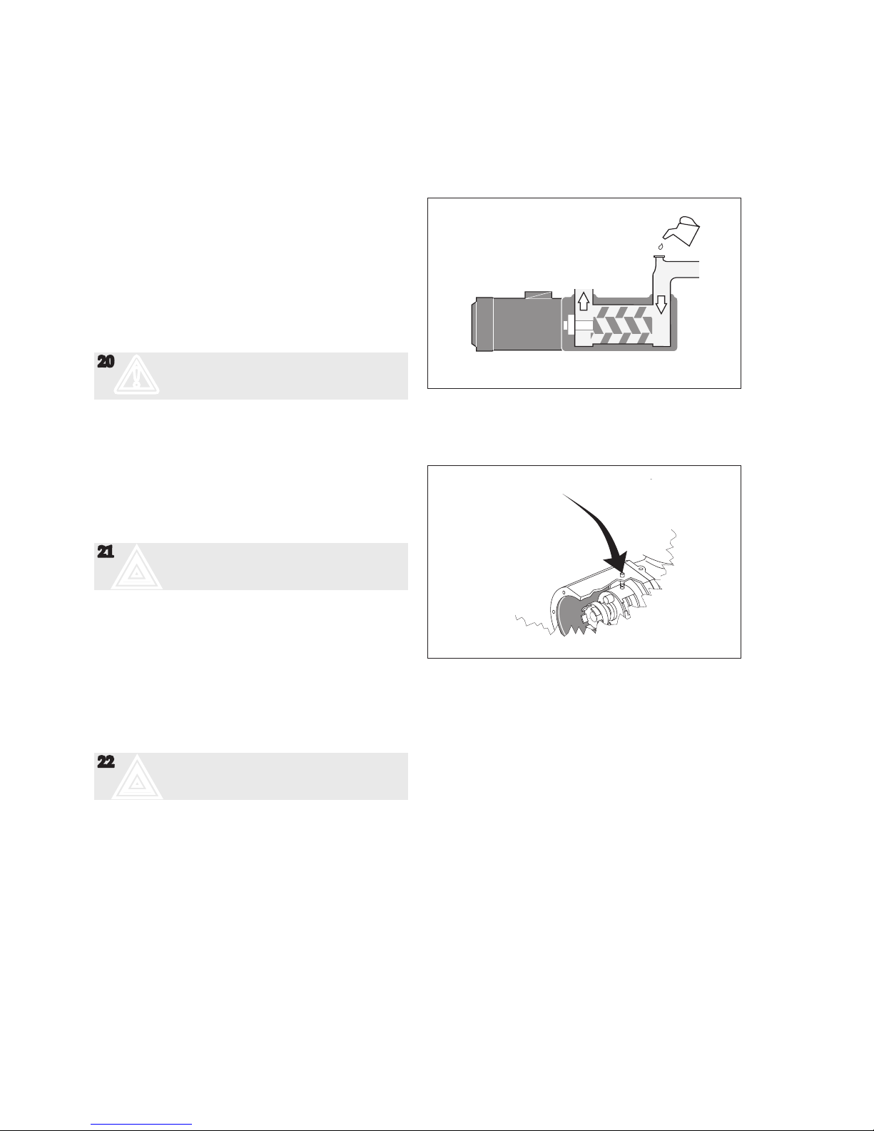
Before starting:
Aer installation and whenever it can be assumed
that the pump has been emptied, the pump must be
thoroughly lled with liquid. See g 8. The ACF type
pumps have been ed with a deaeration plug making venting of the sha seal compartment easy before
start-up.
In installations with positive suction pressure: Aer
opening the inlet and outlet valves, simply open the
deaeration plug a few turns until oil sips out. Tighten
the plug. In installation with negative suction pressure:
Aer opening the inlet and outlet valves, remove the
deaeration plug and ll the sha seal compartment
with oil. Fit and tighten the plug. See g. 9.
20
m
Make sure the prime mover is locked out
and can not be started accidentally.
Rotate the sha by hand while lling the pump, to
ensure that the rotor bores and the sha seal cavity is
lled.
On the ACF pumps, the pump can be turned using the
sha coupling. If the suction pipe cannot be completely
lled, it is important to ensure that the trapped air is
evacuated without any pressure build up. (See g. 9
Deaeration).
21
;
Starting a dry pump is likely to cause
damage, especially to the sha seal.
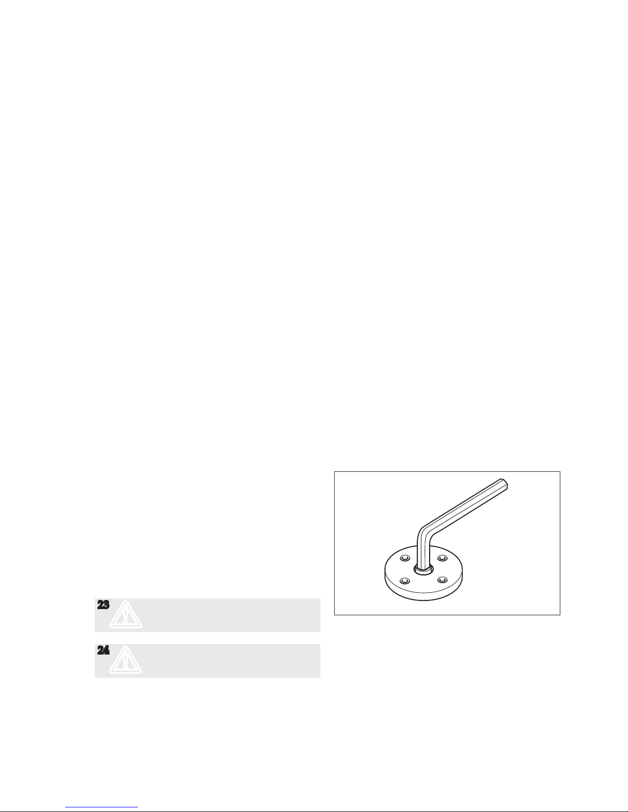
Direction of rotation
When the pump is ready to be started, switch the motor
briey on and o and check that the drive motor rotates
in the correct direction as indicated by the rotation arrow. The arrow is placed on dierent spots depending
on the conguration of the pump unit but can normally
be found on a steel plate that is riveted to the pump
close to the frame that connects the pump and the
electrical motor.
22
;
Don't mix up with arrow for inlet and
outlet!
Safety precautions before starting
If the fan cover on the electrical motor for some reason
should have been removed during the pump installation process do NOT forget to put it back as the rotating
fan can cause seriously personal injuries.
If the protecting cover steel net on the pumps frame
that connects the pump and the electrical motor to each
other has been removed do NOT forget to put it back
as the rotating coupling can cause seriously personal
injuries.
Fig. 8 Filling the pump
Fig. 9 Deaeration plug
Start-up
Page 21
ACF5 0601.01 GB
www.imo.se
21
Starting
Check that all valves necessary for the operation are
fully opened in both discharge and suction lines.
The rst time, the pump should be started with the adjusting spindle of the pressure relief valve tightened to
half of the available turns (the valve seing is increased
when the spindle is turned clockwise). By monitoring the pressure gauge it can be determined when the
suction line is primed and the pump begins to work.
Should the pump not operate normally soon aer start,
stop the pump within half a minute. Start again aer
about 3-5 minutes (the sha seal must have time to cool
o) and run for half a minute. This procedure may need
to be repeated a couple of times if the suction line is
extremely long. Should the pump still not work, it must
be assumed there is a problem in the system that needs
to be remedied. Check the suction line calculation or
see”Trouble shooting”, page 22.
Setting the pressure relief valve
The seing of the opening pressure is made as follows:
Tighten the valve spindle by rotating clockwise to the
maximum extent. The system pressure is regulated by
throling to required value. The pressure relief valve
is eased until the pressure is just beginning to decrease
by turning the spindle CCW. The valve is now preset
for desired opening pressure. Open the throling valve
entirely.
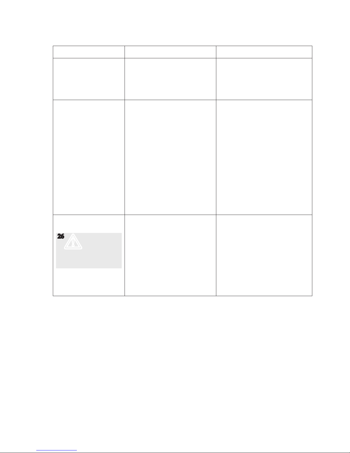
Adjusting the tuning
The tuning adjustment, which is a standard feature on
ACF pumps, is a device for minimizing the eects of
dissolved and free air in lube oil systems. The tuning
principle is described in the Product Description. The
tuning should be adjusted while the pump is working
under normal operating conditions. This is done by
turning the tuning spindle with an Allen key (size 12
mm for ACF) to a position where the noise level comes
to a minimum.
Setting of tuning of the ACF:
1. Before starting the seing, check that the seing
screw are closed.
2. Turn the screw CCW until the noise level becomes
the lowest (if turned too much the noise will increase
again).
Once set, the tuning needs no further adjustment, providing the operating conditions stay the same.
NOTE: It´ s not possible to accidentally turn the tuning
spindle too far as it is internally locked at the end of the
thread.
23
m
If operating temperature exceeds 60°C
(149°F), appropriate measures to avoid
skin contact shall be provided
24
m
Use hearing protection whenever high
noise can be expected from pump, motor
and/or environment.
Fig. 10 Tuning the ACF
Page 22

ACF5 0601.01 GB
www.imo.se
22
Problem Cause What to do
Wrong direction of rotation - Electric cables to motor wrongly
connected.
Reverse the terminal connection on
electric motor.
25
c
Connecting and disconnec-
ting of electric cables must
be done only by personnel
authorized to do such
work.
The pump cannot be
primed
- Wrong direction of rotation.
- Suction line is not open or pressure
drop in the suction line is too high.
- Major air leakage into the suction
line.
- The pump cannot evacuate the air
through the discharge line due to
excessive counter pressure.
See above.
Check all components in suction line.
The inlet condition should be checked
with a vacuum gauge at the pump inlet.
Check the suction line.
See the chapter on Deaeration
(see page 5).
No ow - The pump is not primed.
- The pressure relief valve is set be
-
low the counter pressure.
See above.
Readjust the pressure relief valve to a
value above counter pressure.
Flow too low - The pressure relief valve is set too
low (Discharge pressure also low).
- Something is restricting the ow in
the suction line. (This would usually
cause noise).
- The pumped liquid contains a sig
-
nicant amount of compressible gas,
such as free air. (This would usually
cause noise).
Readjust the pressure relief valve
Check all components in the suction
line (strainers, valves etc.).
See the chapter on Noise and Vibration.
( Page 11).
Pressure too low - The pressure relief valve is set too
low.
- Counter pressure in the discharge
line is too low due to a major leak-
age.
- The valve piston is stuck in open
position.
- Something is restricting the ow in
the suction line. (This would usually
cause noise).
- The pumped liquid contains a sig
-
nicant amount of compressible gas,
such as free air. (This would usually
cause noise).
- A too small pump has been chosen.
Readjust the pressure relief valve.
Check the components in the discharge
line inclusive the recipients.
Check the valve. See Maintenance
and Service instruction for respective
pump.
Check all components in the suction
line (strainers, valves etc.).
See the chapter on Noise and Vibration.
(Page 11).
Contact your IMO AB representative.
Trouble shooting
Page 23
ACF5 0601.01 GB
www.imo.se
23
Problem Cause What to do
Pressure too high - The pressure relief valve is set too
high.
- The oil is too cold (or has higher
viscosity than anticipated).
- Counter pressure in the discharge
line is too high.
Readjust the pressure relief valve.
Reduce the pressure seing until operational temperature has been reached.
Check the discharge line.
Drive motor dicult to
start or tends to stop by
tripping the motor overload
relay
- Counter pressure too high.
- Liquid too cold.
- Motor is undersized for the prevail
-
ing conditions.
- Electrical power supply faulty.
- Motor overload relay set too low or
is faulty.
- Incorrect seing of Y/D starter.
See above: Pressure too high.
Readjust the pressure relief valve to a
lower value. Thus the power consumption for the pumping is relieved and
overloading due to the high viscosity
may be avoided. When the liquid has
reached normal temperature and thus
ows easily, the relief valve is reset to
normal pressure.
Check the motor.
Check the motor and motor connection.
Readjust or replace the relay.
Readjust the seing of the starting
sequence. The time before the motor
overload relay is tripped should not
exceed 10-15 seconds.
Noise and vibration
26
m
Monitor the
pump function
and shut down
if any sign of
malfunction is
noticed
- The ow to the pump is insucient.
- Insucient support of pipe work.
- Bad alignment
- Air leakage into the suction line.
- Free air in the liquid or gas cavita
-
tion.
- Faulty electrical supply.
See chapter: The ow is too low.
Check for pipe vibrations in the pump
connections. Check that the pipes are
suciently clamped.
Check alignment, see page 4.
Check the suction line for air leakage.
For pumps with Tuning:
Adjust the Tuning. If this does not help
or for pumps without Tuning: Contact
your IMO representative or IMO service dept.
Check all three phases of the supply.
Page 24

ACF5 0601.01 GB
IMO AB: P.O. Box 42090, SE 126 14 Stockholm, Sweden
Telephone: +46 8 50 622 800, Telefax: +46 8 645 1509
www.imo.se
IMO AB: P.O. Box 42090, SE 126 14 Stockholm, Sweden
Telephone: +46 8 50 622 800, Telefax: +46 8 645 1509
 Loading...