

i-MO 540 Series, 520 Series Product Installation Manual

Product Installation Manual
i-MO 540 Series Bonding Router
Installation Manual
for the i-MO 540 Series Appliance

INSTALLATION MANUAL FOR THE EMS I-MO 540 SERIES APPLIANC E
Version 1.2
ELECTRONIC MEDIA SERVICES LIMITED
PASSFIELD BUSINESS CENTRE, LYNCHBOROUGH ROAD, LIPHOOK, HAMPSHIRE, GU30 7SB, UK
Tel:
01428 751655 |
Fax:
01428 751654 |
E-mail:
imo@ems-uk.com
Page 2 of 58
Content
Content .............................................................................................................................................................. 2
I-MO Appliance Identification Guide .................................................................................................................. 4
General Safety Guidelines for EMS Hardware Equipment ................................................................................ 5
Installation Safety Guidelines and Warnings ..................................................................................................... 5
Rack-Mounting Requirements (Optional) ...................................................................................................... 5
Operating Temperature Warning ................................................................................................................... 6
Product Disposal Warning ............................................................................................................................. 6
General Electrical Safety Warnings for EMS Hardware Equipment .................................................................. 6
Radio Frequency Interference ....................................................................................................................... 6
Electromagnetic Compatibility ....................................................................................................................... 6
AC Power Electrical Safety Guideli nes .......................................................................................................... 6
Hardware Installation Guide .............................................................................................................................. 7
1) Installing the Rack mount kit (optional) ..................................................................................................... 7
2) Attach WiFi antennas (optional) ................................................................................................................ 7
3) Attach 3G/4G antennas and cables .......................................................................................................... 7
4) Attach network cables (optional) ............................................................................................................... 8
5) Install SIM cards ........................................................................................................................................ 8
6) Power cable ............................................................................................................................................... 9
7) Power switch ........................................................................................................................................... 10
7) Status display .......................................................................................................................................... 11
Web Configuration ........................................................................................................................................... 12
General Section Configuration .................................................................................................................... 12
Home ....................................................................................................................................................... 12
My Profile ................................................................................................................................................. 13
Log out ..................................................................................................................................................... 14
Network Section Configuration .................................................................................................................... 14
Edit Configuration .................................................................................................................................... 14
NAS .......................................................................................................................................................... 23
Command Line Interface ............................................................................................................................. 24
Appendix A - Optional WiFi Radio Component ............................................................................................... 28
Warnings ...................................................................................................................................................... 28
Regulatory Notices ...................................................................................................................................... 28
FCC ID: N7N-MHS802 ................................................................................................................................ 28
Certification Information (SAR) .................................................................................................................... 29
Technical Data ............................................................................................................................................. 29
Safety Regulation and Operating Environment ........................................................................................... 29

INSTALLATION MANUAL FOR THE EMS I-MO 540 SERIES APPLIANC E
Version 1.2
ELECTRONIC MEDIA SERVICES LIMITED
PASSFIELD BUSINESS CENTRE, LYNCHBOROUGH ROAD, LIPHOOK, HAMPSHIRE, GU30 7SB, UK
Tel:
01428 751655 |
Fax:
01428 751654 |
E-mail:
imo@ems-uk.com
Page 3 of 58
Optional WiFi Radio Aerial........................................................................................................................... 30
Appendix B - Optional 3G Radio Component .................................................................................................. 31
External Installation ..................................................................................................................................... 31
Appendix C ...................................................................................................................................................... 33
Access Point Name File............................................................................................................................... 33
Appendix D ...................................................................................................................................................... 34
Configuration File ......................................................................................................................................... 34
Example 1. 1 x WAN Link, 1 X LTE for failover without a Concentrator ..................................................... 42
Example 2. 1 x Wan Link, 1 X LTE for failover with a Concentrator .......................................................... 45
Example 3. 1 x WAN Link, 1 X LTE for failover with a Concentrator & split routing................................... 48
Appendix E ...................................................................................................................................................... 51
Configuration Options Reference ................................................................................................................ 51
Appendix F - Disposal and Recycling Information ........................................................................................... 55
WEEE EU Directive ..................................................................................................................................... 55
Reduction of Hazardous Substanc es .......................................................................................................... 55
Appendix G - Warranty Information ................................................................................................................. 56
Obtaining Technical Assistance ...................................................................................................................... 58
INSTALLATION MANUAL FOR THE EMS I-MO 540 SERIES APPLIANC E
Version 1.2
ELECTRONIC MEDIA SERVICES LIMITED
PASSFIELD BUSINESS CENTRE, LYNCHBOROUGH ROAD, LIPHOOK, HAMPSHIRE, GU30 7SB, UK
Tel:
01428 751655 |
Fax:
01428 751654 |
E-mail:
imo@ems-uk.com
Page 4 of 58
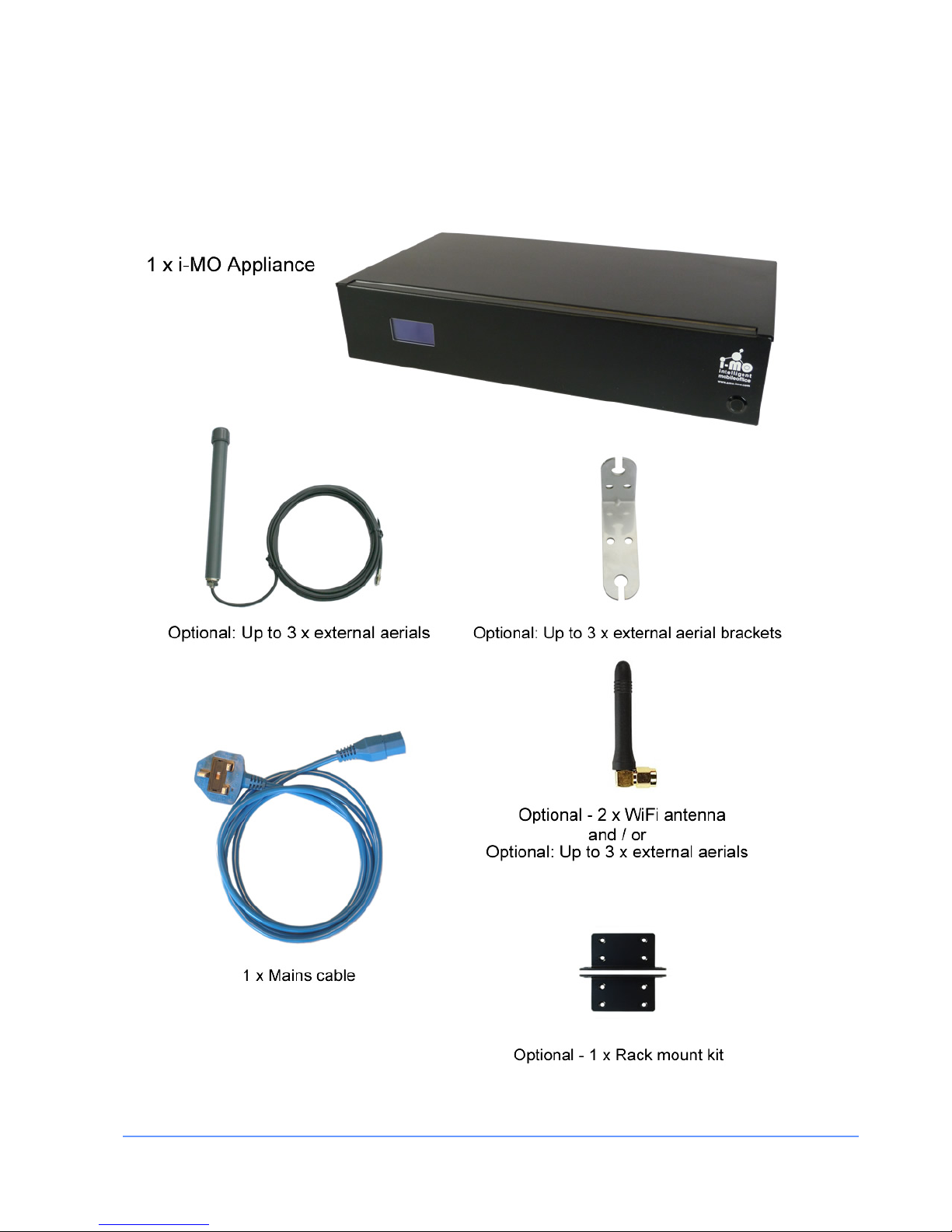
I-MO Appliance Identification Guide
The following diagram shows the basic and optional i-MO hardware components.

INSTALLATION MANUAL FOR THE EMS I-MO 540 SERIES APPLIANC E
Version 1.2
ELECTRONIC MEDIA SERVICES LIMITED
PASSFIELD BUSINESS CENTRE, LYNCHBOROUGH ROAD, LIPHOOK, HAMPSHIRE, GU30 7SB, UK
Tel:
01428 751655 |
Fax:
01428 751654 |
E-mail:
imo@ems-uk.com
Page 5 of 58
General Safety Guideline s f or EMS Hardware Equipment
The following guidelines help ensure your safety and protect the hardware equipment from damage. The list
of guidelines might not address all potentially hazardous situations in your working environment, so be alert
and exercise good judgment at all times.
• Perform only the procedures explicitly described in this documentation. Make sure that only
authorized service personnel perform other system services.
• Keep the area around the chassis clear and free from dust before, during, and after installation.
• Keep tools away from areas where people could trip over them while walking.
• Wear safety glasses if you are working under any conditions that could be hazardous to your eyes.
• Do not perform any actions that create a potential hazard to people or make the equipment unsafe.
• Never install or manipulate wiring during electrical storms.
• Never install electrical jacks in wet locations unless the jacks are specifically designed for wet
environments.
• Operate the hardware equipment only when the chassis is properly grounded.
• Do not open or remove chassis covers or sheet metal parts unless instructions are provided in this
documentation. Such an action could cause severe electrical shock.
• Do not push or force any objects through any opening in the chassis frame. Such an action could
result in electrical shock or fire.
• Avoid spilling liquid onto the chassis or onto any hardware component. Such an action could cause
electrical shock or damage the hardware equipment.
• Do not use the device where inflammables or explosives are stored, for example, in a fuel station, oil
depot, or chemical plant. Otherwise, explosions or fires may occur.
• Use only the accessories supplied or authorized by the device manufacturer. Otherwise, the
performance of the device may get affected, the warranty for the device or the laws and regulations
related to telecommunications terminals may become null and void, or an injury may occur.
• Do not use the power adapter if its cable is damaged. Otherwise, electric shocks or fires may occur.
• Do not use the antennas if the connectors, cables, or antennas are damaged. Otherwise, radio
frequency interference or electric shock may occur.
Installation Safety Guidelines and Warnings
Read the installation instructions before you connect the hardware equipment to a power source.
Rack-Mounting Requirements (Optional)
Ensure that the equipment rack into which the chassis is installed is evenly and securely supported, to avoid
the hazardous condition that could result from uneven mechanical loading.

INSTALLATION MANUAL FOR THE EMS I-MO 540 SERIES APPLIANC E
Version 1.2
ELECTRONIC MEDIA SERVICES LIMITED
PASSFIELD BUSINESS CENTRE, LYNCHBOROUGH ROAD, LIPHOOK, HAMPSHIRE, GU30 7SB, UK
Tel:
01428 751655 |
Fax:
01428 751654 |
E-mail:
imo@ems-uk.com
Page 6 of 58
Operating Temperature Warning
To prevent the hardware equipment from overheating, do not operate it in an area that exceeds the
maximum recommended ambient temperature of 40°C. To prevent airflow restriction, allow at least 2 inches
of clearance around the rear ventilation grille.
Do not expose to direct sunlight.
Do not place containers of liquids on the device or allow the device to come in contact with liquids.
Do not place near or on a source of heat.
Product Disposal Warning
Disposal of this product must be handled according to all national laws and regulations.
See
Appendix F for details.
General Electrical Safety Warnings for EMS Hardware Equipment
Radio Frequency Interference
You can reduce or eliminate the emission of radio frequency interference (RFI) from your site wiring by using
twisted-pair network cabling with a good distribution of grounding conductors. If you must exceed the
recommended distances, use a high-quality twisted-pair cable with one ground conductor for each data
signal when applicable.
Electromagnetic Compatibility
If your site is susceptible to problems with electromagnetic compatibility (EMC), particularly from lightning or
radio transmitters, you might want to seek expert advice. Strong sources of electromagnetic interference
(EMI) can destroy the signal drivers and receivers in the router and conduct power surges over the lines into
the equipment, resulting in an electrical hazard. It is particularly important to provide a properly grounded
and shielded environment and to use electrical surge-suppression devices.
AC Power Electrical Safety Guidelines
The i-MO requires an AC supply of 100-240Volts, 50/60Hz and can draw a current of up to 2 Amps.
i-MO routers are shipped with a three-wire electrical cord with a grounding-type plug that fits only a
grounding-type power outlet. Do not circumvent this safety feature. Equipment grounding should comply with
local and national electrical codes. The power cord serves as the main disconnecting device. The socket
outlet must be near the router and be easily accessible.
INSTALLATION MANUAL FOR THE EMS I-MO 540 SERIES APPLIANC E
Version 1.2
ELECTRONIC MEDIA SERVICES LIMITED
PASSFIELD BUSINESS CENTRE, LYNCHBOROUGH ROAD, LIPHOOK, HAMPSHIRE, GU30 7SB, UK
Tel:
01428 751655 |
Fax:
01428 751654 |
E-mail:
imo@ems-uk.com
Page 7 of 58
Hardware Installation Guide
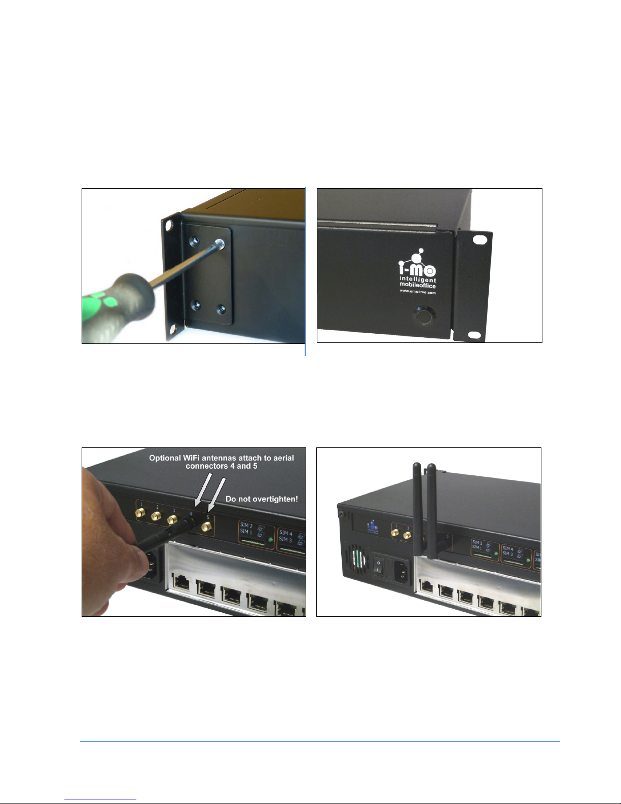
1) Installing the Rack mount kit (optional)
This stage is only required if you plan to mount the appliance in a communications rack. The rack mount kit
includes 2 brackets and 8 screws.
The brackets are symmetrical and can be installed on either side. See pictures below.
2) Attach WiFi antennas (optional)
The i-MO appliance is supplied with a WiFi interface. This can be enabled on request at time of order. If the
WiFi interface is enabled install the two antennas on the aerial connectors numbered 4 and 5 as shown
below.
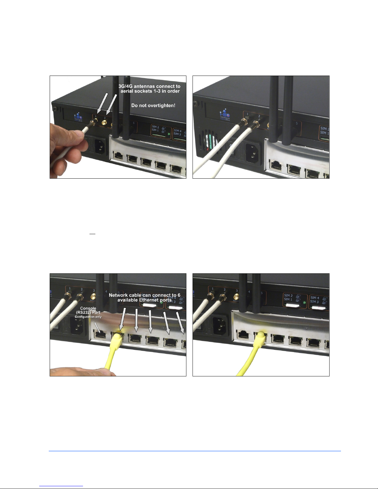
3) Attach 3G/4G antennas and cables
Up to 3 antennas may be provided dependent upon the number of modems installed. The antennas must be
mounted outside and as high as possible. The antennas should be spaced at least 1 metre apart from each
other.
INSTALLATION MANUAL FOR THE EMS I-MO 540 SERIES APPLIANC E
Version 1.2
ELECTRONIC MEDIA SERVICES LIMITED
PASSFIELD BUSINESS CENTRE, LYNCHBOROUGH ROAD, LIPHOOK, HAMPSHIRE, GU30 7SB, UK
Tel:
01428 751655 |
Fax:
01428 751654 |
E-mail:
imo@ems-uk.com
Page 8 of 58
The connector on each aerial cable should be attached to the aerial sockets (1-3) as shown below.
Note: Connectors should be touch tight only! Do not over tighten.
4) Attach network cables (optional)
The i-MO appliance provides six Ethernet ports at the rear. Each of these can be individually configured as
WAN or LAN ports. Network cables (not provided) can be connected as shown below. The default
configuration is all
ports configured for LAN usage (6 port network hub).
Note: The first port on the left as viewed from the rear is a Console (RS232) Port available for unit
configuration purposes only. This port is NOT available for network use.
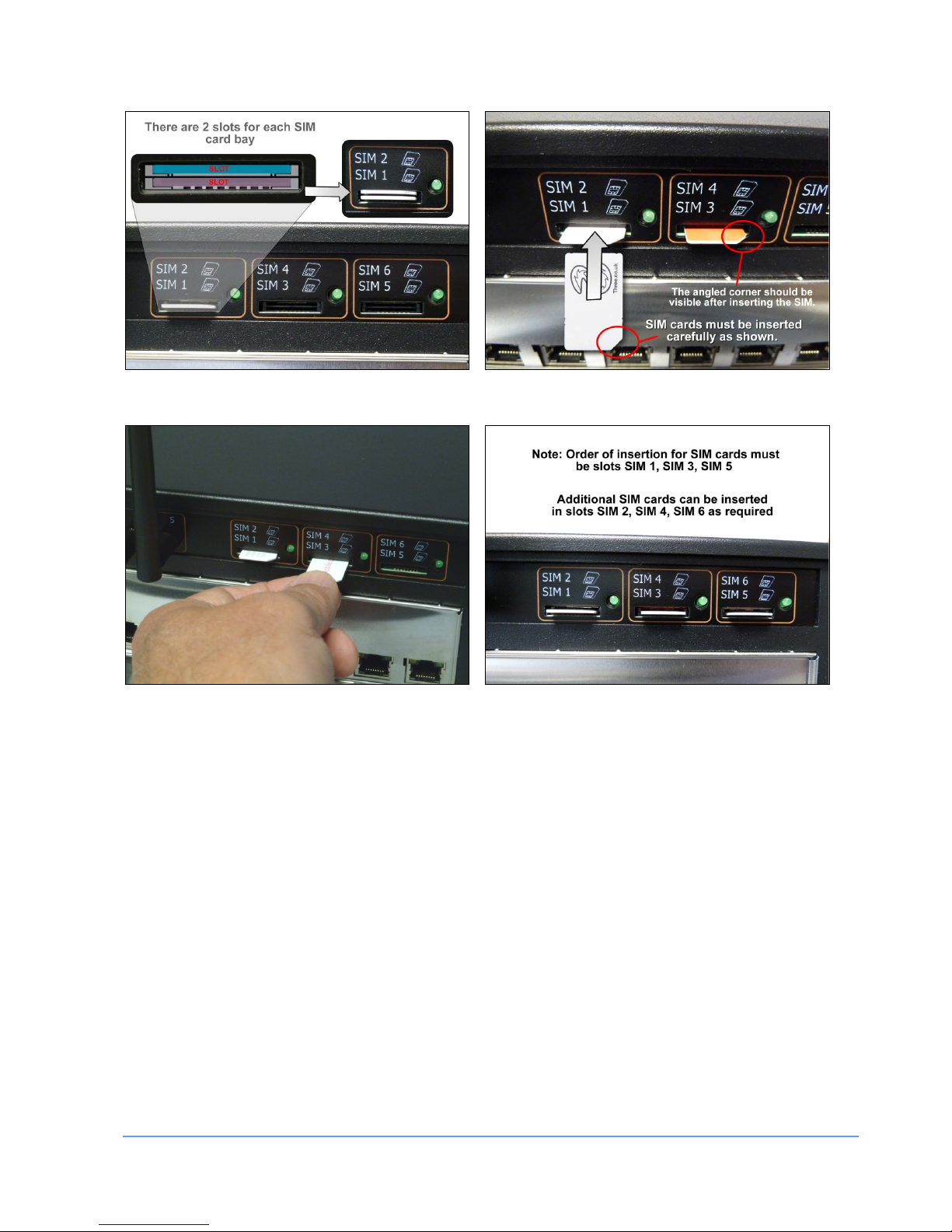
5) Install SIM cards
The appliance supports up to 6 SIMs which are installed in the SIM card slots on the rear of the appliance as
illustrated below.
INSTALLATION MANUAL FOR THE EMS I-MO 540 SERIES APPLIANC E
Version 1.2
ELECTRONIC MEDIA SERVICES LIMITED
PASSFIELD BUSINESS CENTRE, LYNCHBOROUGH ROAD, LIPHOOK, HAMPSHIRE, GU30 7SB, UK
Tel:
01428 751655 |
Fax:
01428 751654 |
E-mail:
imo@ems-uk.com
Page 9 of 58
• Note: Please ensure you insert the SIM cards carefully in their slots and ensure that they are
pressed in as illustrated above
• Note: Up to six SIMs can be inserted - start ing with slo ts SIM 1, SIM 3 and SIM 5
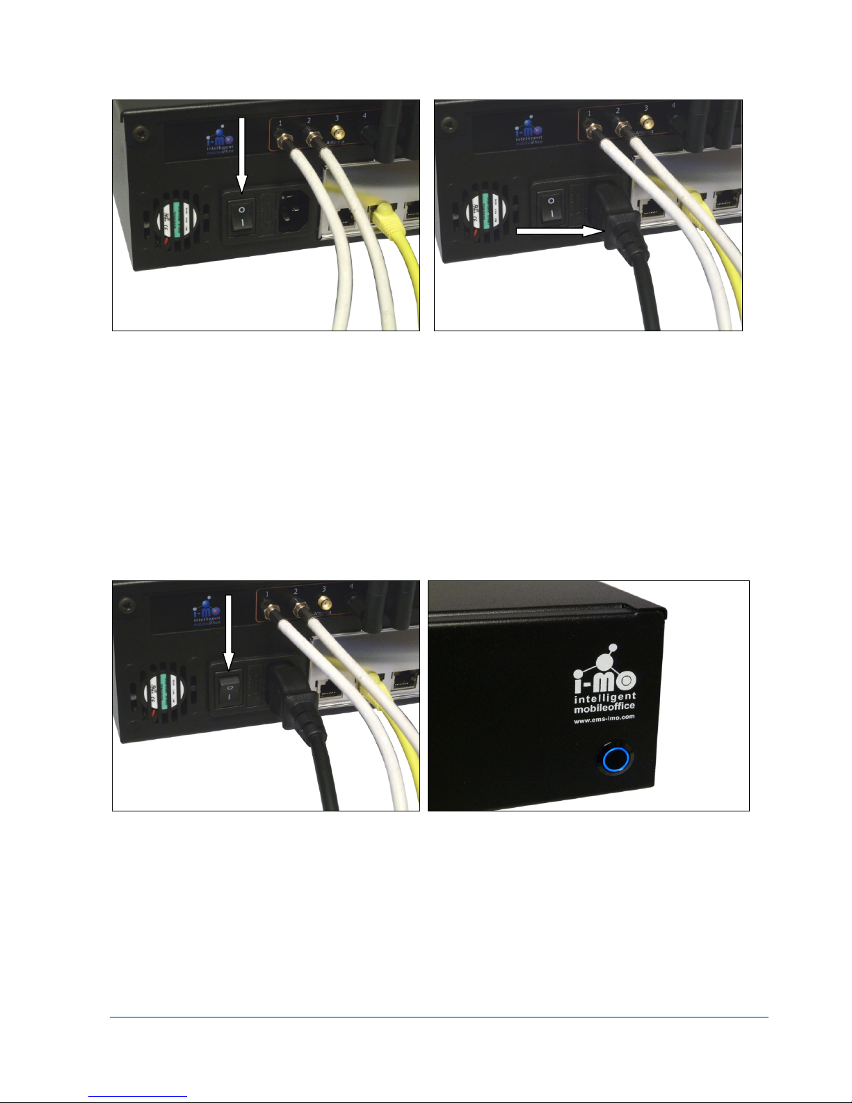
6) Power cable
The appliance is powered by a standard 200~240V supply. The power input is switched. Please ensure the
switch is set to the off position (0) before inserting the power cable as shown below.
Note: We recommend the use of UPS units where power regulation cannot be guaranteed (e.g. use of a
generator)
INSTALLATION MANUAL FOR THE EMS I-MO 540 SERIES APPLIANC E
Version 1.2
ELECTRONIC MEDIA SERVICES LIMITED
PASSFIELD BUSINESS CENTRE, LYNCHBOROUGH ROAD, LIPHOOK, HAMPSHIRE, GU30 7SB, UK
Tel:
01428 751655 |
Fax:
01428 751654 |
E-mail:
imo@ems-uk.com
Page 10 of 58
7) Power switch
Mains power to the unit is supplied via a power input at the rear of the unit as shown below. To switch the
unit on the power switch should be set to the on position (1).
The power switch at the front of the unit is used to turn the appliance on (boot) or of f (shutdown). As soon as
the button is pressed it will illuminate to show that the appliance is powering up. Press the button again to
start the power off sequence. The message on the status display will change and when the po wer off sequence has completed the light in the button will extinguish.
Note: Do NOT hold the power button in unless specifically instructed to do so by a support engineer
INSTALLATION MANUAL FOR THE EMS I-MO 540 SERIES APPLIANC E
Version 1.2
ELECTRONIC MEDIA SERVICES LIMITED
PASSFIELD BUSINESS CENTRE, LYNCHBOROUGH ROAD, LIPHOOK, HAMPSHIRE, GU30 7SB, UK
Tel:
01428 751655 |
Fax:
01428 751654 |
E-mail:
imo@ems-uk.com
Page 11 of 58
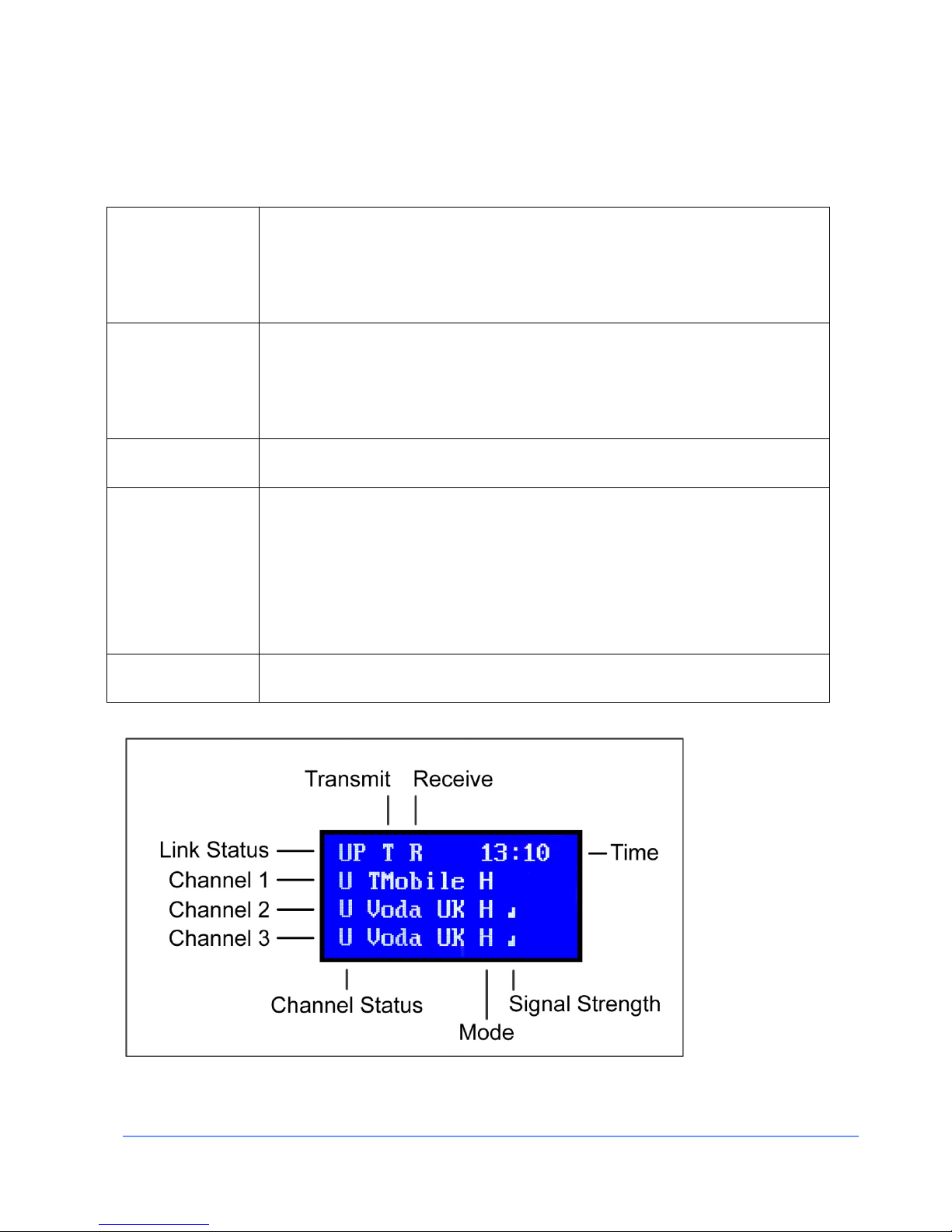
7) Status display
The LCD display shows the status of up to three mobile connections plus the overall status of the link.
Link Status
This shows the overall status of the link which can either be UP or DOWN. When
the link is DOWN the appliance is not able to send or receive data.
Just to the right of the link status the letters T and R will flash when the appliance
is Transmitting or Receiving data.
Mobile Status
This shows the status of each mobile channel. The letter U will be displayed when
the link is UP and D is displayed when the link is DOWN.
The status will also flash T and R when the channel is transmitting or receiving
data.
Network
This shows the name of the network the appliance is using.
Mode
The standard appliance currently supports five network protocols: GPRS, EDGE,
3G, HSDPA and HSPA+.
The letter G is displayed for GPRS, E for EDGE, 3 for 3G and H for HSDPA or
HSPA+ modes.
Note: If one or more 4G compatible modems are fitted then those channels will
also support the 4G protocol. The digit 4 will then be displayed.
Signal Strength
This shows the strength of the signal being received from the mobile network.
INSTALLATION MANUAL FOR THE EMS I-MO 540 SERIES APPLIANC E
Version 1.2
ELECTRONIC MEDIA SERVICES LIMITED
PASSFIELD BUSINESS CENTRE, LYNCHBOROUGH ROAD, LIPHOOK, HAMPSHIRE, GU30 7SB, UK
Tel:
01428 751655 |
Fax:
01428 751654 |
E-mail:
imo@ems-uk.com
Page 12 of 58
Web Configuration
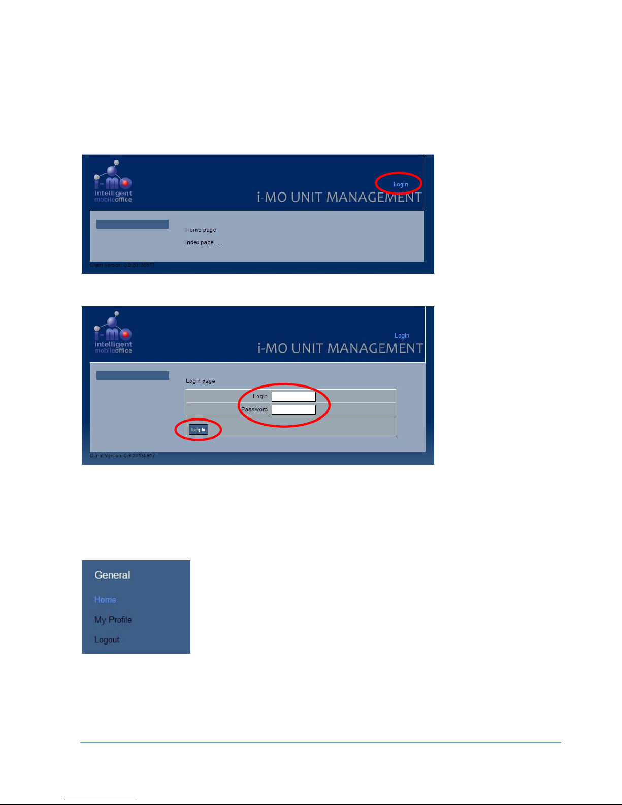
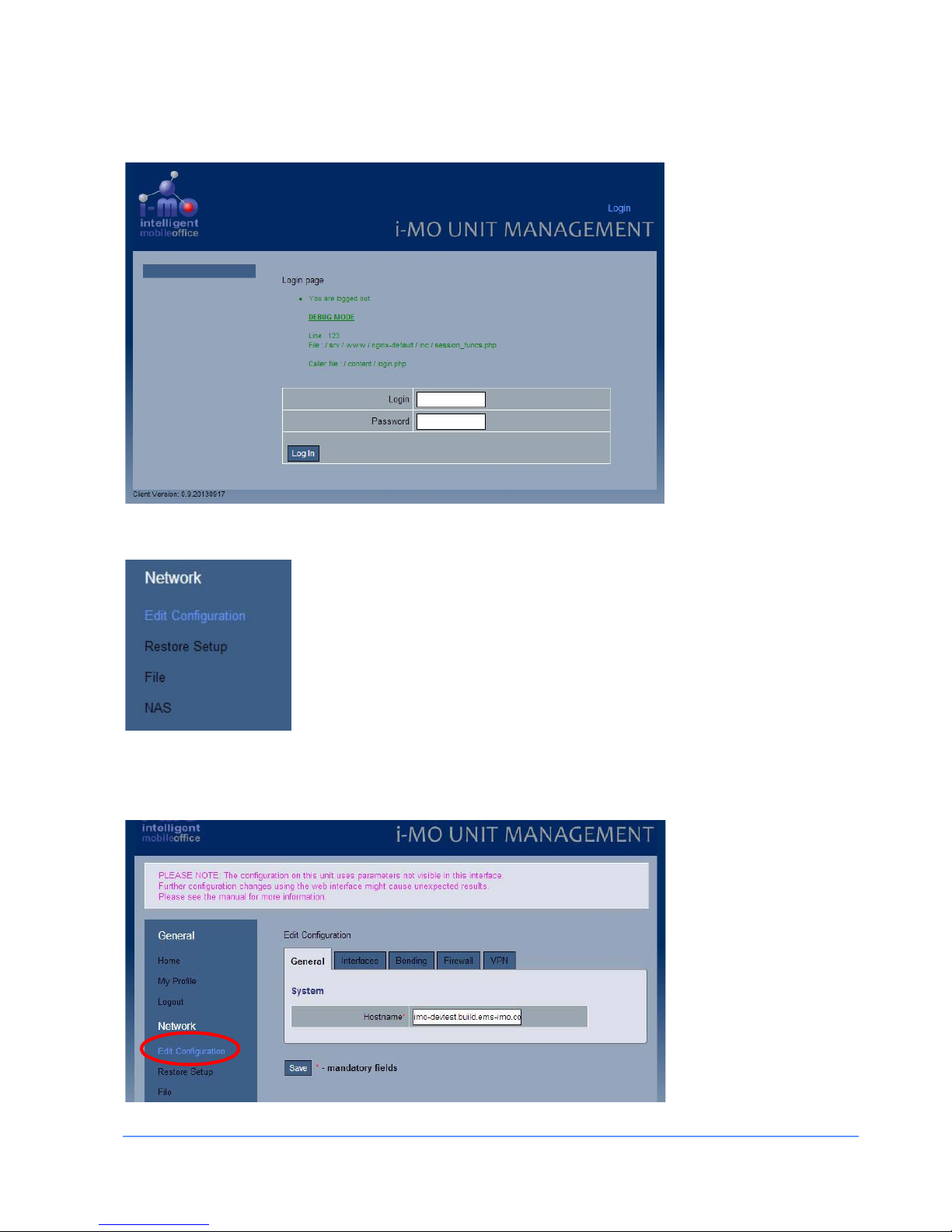
The i-MO appliance can easily be configured and managed using the web interface.
Enter the default url: http://192.168.0.1/ and select the "Login" option from the top right hand side of the
page.
This will load the Login page:
Enter your username and password and click the Login button. The default administrator username is admin
and the password is admin.
It is strongly recommend that the default password is changed using the “My Profile” page.
General Section Configuration
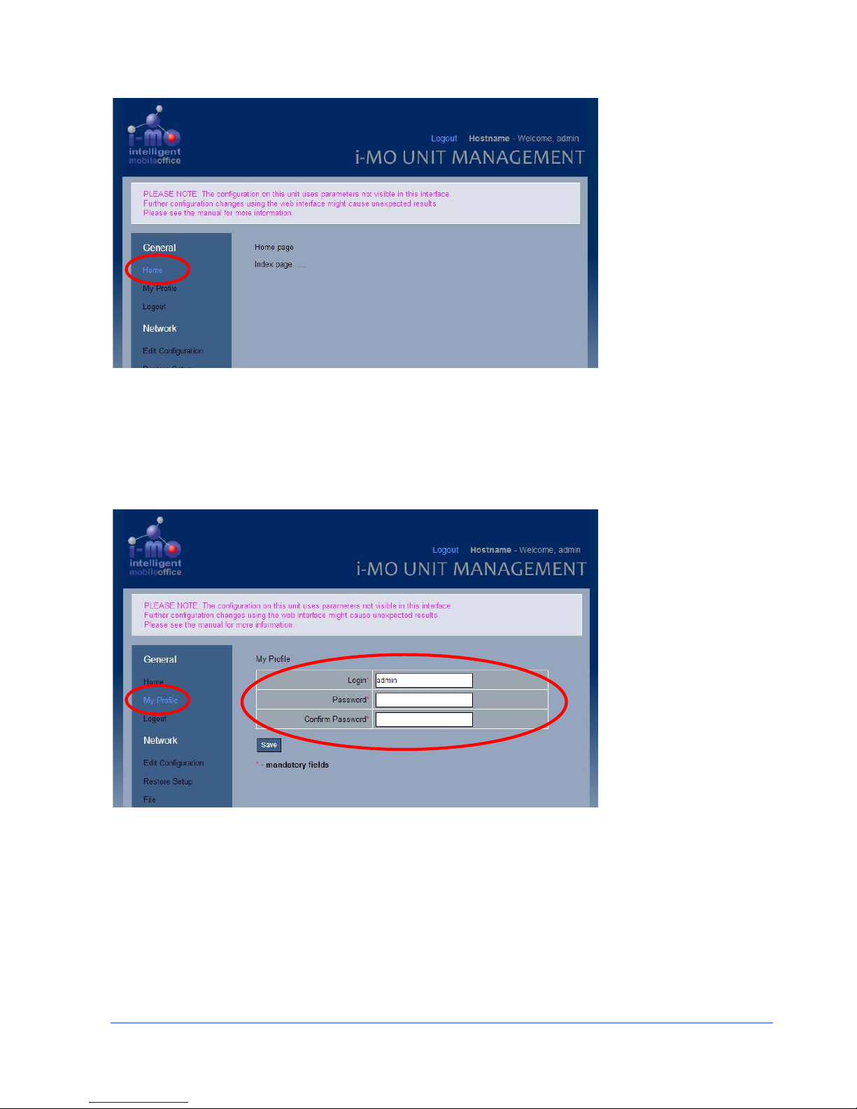
Home
The current home page has no content.
INSTALLATION MANUAL FOR THE EMS I-MO 540 SERIES APPLIANC E
Version 1.2
ELECTRONIC MEDIA SERVICES LIMITED
PASSFIELD BUSINESS CENTRE, LYNCHBOROUGH ROAD, LIPHOOK, HAMPSHIRE, GU30 7SB, UK
Tel:
01428 751655 |
Fax:
01428 751654 |
E-mail:
imo@ems-uk.com
Page 13 of 58
My Profile
The "My profile" option allows you to change your password.
There is no mechanism to recover a forgotten password and if the password has been forgotten then the
factory reset is required to restore the default password.
It is strongly recommend that the defaul t p assword is changed using this page.
INSTALLATION MANUAL FOR THE EMS I-MO 540 SERIES APPLIANC E
Version 1.2
ELECTRONIC MEDIA SERVICES LIMITED
PASSFIELD BUSINESS CENTRE, LYNCHBOROUGH ROAD, LIPHOOK, HAMPSHIRE, GU30 7SB, UK
Tel:
01428 751655 |
Fax:
01428 751654 |
E-mail:
imo@ems-uk.com
Page 14 of 58
Log out
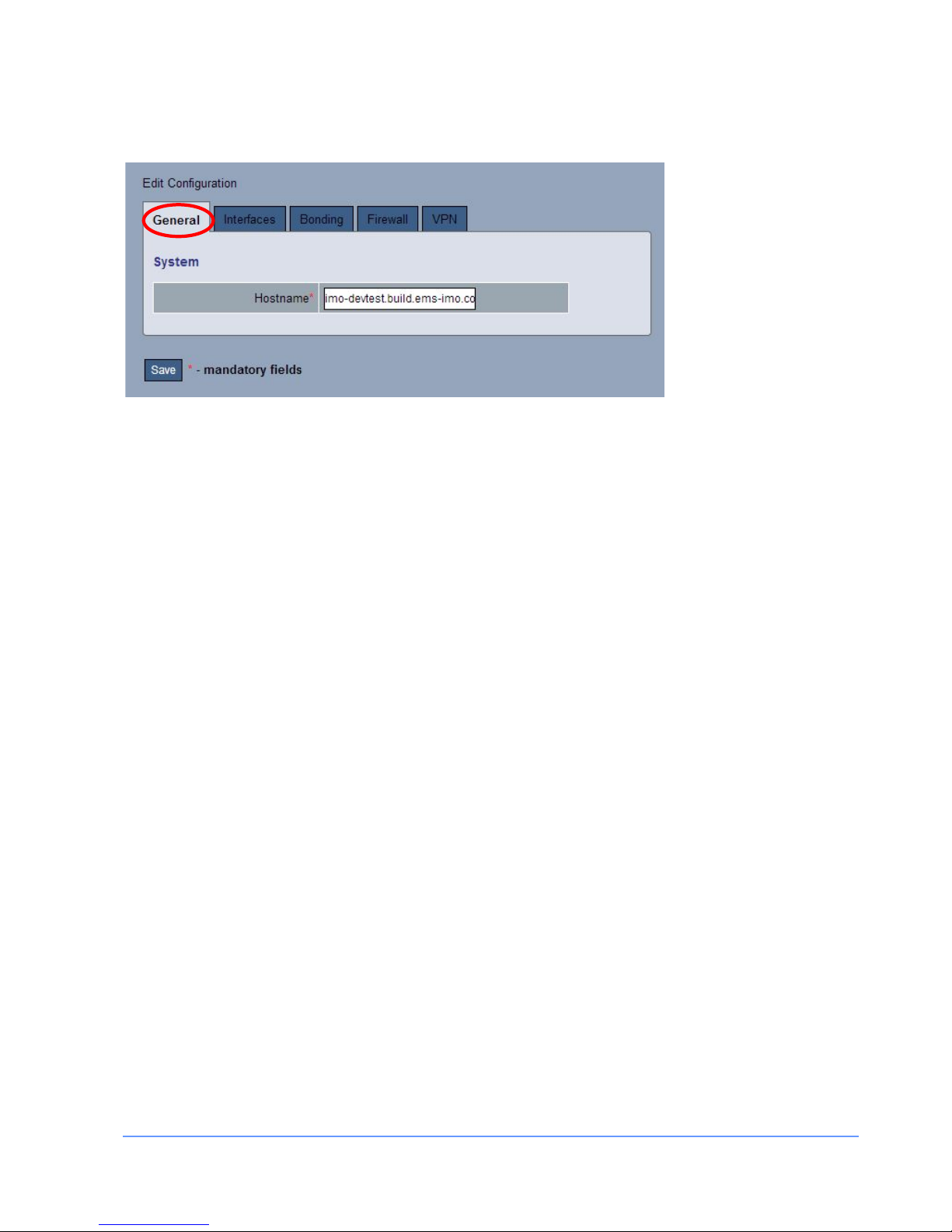
Network Section Configuration
Edit Configuration
The configuration of the network is managed using the Network Configuration menu and the associated
tabbed pages.
INSTALLATION MANUAL FOR THE EMS I-MO 540 SERIES APPLIANC E
Version 1.2
ELECTRONIC MEDIA SERVICES LIMITED
PASSFIELD BUSINESS CENTRE, LYNCHBOROUGH ROAD, LIPHOOK, HAMPSHIRE, GU30 7SB, UK
Tel:
01428 751655 |
Fax:
01428 751654 |
E-mail:
imo@ems-uk.com
Page 15 of 58
General Tab
The host name of the i-MO appliance can be set on the "General" tab.
It must be RFC952 compliant. The host name can be up to 24 characters long and consist of letters (a-z),
numbers 0-9), minus sign (-), and period (.). The periods are nor mally used to delimit components of a
"domain style" name (See RFC-921). It must not contain blank or space characters. The host name is case
insensitive and letters may be upper or lower case. The first character must be a letter.
Valid examples:
i-mo.1234.mydomain.com
my-imo
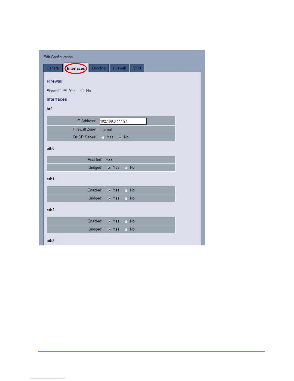
Interfaces Tab (Image 1)
The i-MO 310 and 540 appliances have 6 Gb Ethernet ports plus an optional wireless 802.11 b/g/n wireless
interface. The GbE interfaces are named eth0 through eth5 and the wireless interface is named wlan0.
All of the physical devices can be individually configured and can be assigned to internal, dmz, or external
zones in the firewall.
One or more physical interfaces can be combined into a single logical interface (br0). The logical interface is
like an Ethernet switch and MAC address to physical port mappings are typically remembered for up to 5
minutes before traffic for a given address is broadcast to all ports again.
The IP address of the interfaces should be specified using a CIDR which is a representation of an IP address
and its associated routing prefix, for example: 192.168.0.1/24 or 10.0.0.1/16
In the following example the firewall is enabled and all the Ethernet ports (0-5) plus the WiFi interface
(wlan0) are assigned to the bridge interface (br0).
The bridge interface is assigned to the “internal” zone and the IP address is set to 192.168.0.111 and the
DHCP server is enabled and will issue IP address from the range 192.168.0.100 to 192.168.0.200 inclusive.
The additional DHCP options for the DNS and WINS servers and the DNS search domain can be set in the
DHCP setting.
In the wlan0 section you can specify the “service set identifier “ (SSID) or name that will be broadcast. The
SSID may be up to 31 characters long and can contain upper and lowercase letters (A-Z, a-z) or numbers (0-
9). It may also include any punctuation except the following: ", $, [, \, ], and +, it cannot start with a !, # or ;
character. For example:
my-wifi
INSTALLATION MANUAL FOR THE EMS I-MO 540 SERIES APPLIANC E
Version 1.2
ELECTRONIC MEDIA SERVICES LIMITED
PASSFIELD BUSINESS CENTRE, LYNCHBOROUGH ROAD, LIPHOOK, HAMPSHIRE, GU30 7SB, UK
Tel:
01428 751655 |
Fax:
01428 751654 |
E-mail:
imo@ems-uk.com
Page 16 of 58
The WiFi password (shared key) must be between 8 and 63 characters long and can contain any printable
character.
INSTALLATION MANUAL FOR THE EMS I-MO 540 SERIES APPLIANC E
Version 1.2
ELECTRONIC MEDIA SERVICES LIMITED
PASSFIELD BUSINESS CENTRE, LYNCHBOROUGH ROAD, LIPHOOK, HAMPSHIRE, GU30 7SB, UK
Tel:
01428 751655 |
Fax:
01428 751654 |
E-mail:
imo@ems-uk.com
Page 17 of 58
Interfaces Tab (Image 2)
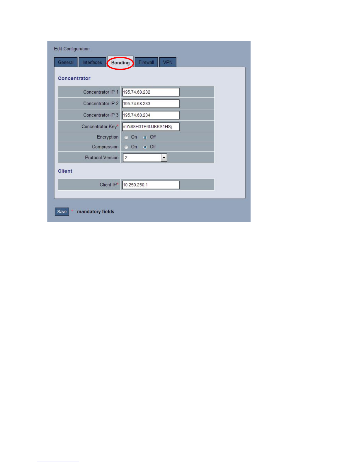
Bonding Tab
The “Bonding” tab configures a single tunnel that is used for bonding multiple physical links into a single
logical link. More complicated bonding configurations (e.g. over WAN links) can configure using the
configuration file, see
Appendix D.
INSTALLATION MANUAL FOR THE EMS I-MO 540 SERIES APPLIANC E
Version 1.2
ELECTRONIC MEDIA SERVICES LIMITED
PASSFIELD BUSINESS CENTRE, LYNCHBOROUGH ROAD, LIPHOOK, HAMPSHIRE, GU30 7SB, UK
Tel:
01428 751655 |
Fax:
01428 751654 |
E-mail:
imo@ems-uk.com
Page 18 of 58
You need to specify a unique Concentrator IP for each cellular modem that is installed.
The Concentrator Key is a shared secret used to authenticate the i-MO appliance with the Concentrator. The
randomness and length of the key affects the quality of the encryption if enabled. For applications that
require good security you should use a 16 or 32 character key and it should consist of numbers plus upper
and lower case letters. Standard diction ary words should not be used.
This is an example of a poor key: thisismykey
This is a much stronger key: vjXt3Z7bqw6rjUXe
Traffic over the tunnel can be encrypted setting encrypt option equal to yes. The default encryption is
Blowfish 128.
The compress option enables compression of data sent over the bonded channel.
The protocol version allows for communication with Concentrators running different i-MO releases. It should
normally be configured for a value of 2.
The Client IP is the internal endpoint of the tunnel on the i-MO appliance which is used on the Concentrator
for routing and must be unique.
Firewall Tab
The Firewall tab configures various options for the firewall.
 Loading...