

Page 1
1
EzAntennaTracker-Lite
Overview & Operating Instructions
Preliminary. April 2009
Page 2

2
Table of Contents
1. Table of Contents .......................................................................................................................2
2. Overview ....................................................................................................................................4
3. Installation .................................................................................................................................5
3.1. Airborne Electronics ...................................................................................................................... 5
3.2. Ground Station Electronics ........................................................................................................... 5
3.3. Only the AUDR (Audio, Right), and Ground pins are connected on this connector. .................... 5
3.4. Cabling, Getting the Correct Audio Channel ................................................................................. 6
3.5. Transmitter Audio Connection ...................................................................................................... 6
3.5.1. ImmersionRC/Airwave Transmitter ...................................................................................... 6
3.5.2. Lawmate Transmitter ............................................................................................................ 7
3.6. Receiver Audio Connection ........................................................................................................... 7
3.6.1. ImmersionRC/Airwave receivers........................................................................................... 7
3.6.2. Lawmate Receivers ............................................................................................................... 8
3.7. Lawmate Transmitter, Airwave Receiver ...................................................................................... 8
3.8. Checking, and Debugging Audio Issues ......................................................................................... 9
3.9. Recording telemetry ..................................................................................................................... 9
3.10. Suitable Pan/Tilt mounts ......................................................................................................... 10
3.10.1. ServoCity Medium-Duty ...................................................................................................... 10
3.11. Low cost alternatives .............................................................................................................. 10
3.12. Do I really need a Tilt axis?...................................................................................................... 11
3.13. Servo Splines ........................................................................................................................... 11
4. Configuration ........................................................................................................................... 12
4.1. Setup Menu ................................................................................................................................. 12
4.1.1. Description of Controls ....................................................................................................... 12
4.2. Setting up the servos .................................................................................................................. 15
4.2.1. Servo Setup Step #1: Defining the zero position ................................................................ 15
4.2.2. Servo Setup Step #2: Setting up servo reverses ................................................................. 15
4.2.3. Servo Setup Step #3: Setting up servo gains ....................................................................... 15
4.2.4. Servo Setup Step #4: Setting up tilt servo limits ................................................................. 15
4.3. Example settings ......................................................................................................................... 16
4.3.1. ServoCity pan/tilt mount , SPG785 Pan (2:1, 630 degree option), DDT500H Tilt .............. 16
4.3.2. GWS/SuperTec S125 (for pan axis only) ............................................................................. 16
5. Flight ........................................................................................................................................ 17
Page 3

3
5.1. Status Pages ................................................................................................................................ 17
5.2. Calibration ................................................................................................................................... 18
1) Manually, using a compass. ............................................................................................................ 18
2) Automatically, using the GPS in the plane ...................................................................................... 18
5.3. .......................................................................................................................................................... 19
6. Replaying recorded telemetry data ........................................................................................... 19
7. Frequently Asked Questions ..................................................................................................... 19
Page 4
4
1. Overview
The EzAntennaTracker system, is the first commercially available antenna tracker designed for FPV/UAV
flight.
It operates by sending a digital telemetry stream down one of the audio channels of an A/V link, via the
EzOSD module. This telemetry stream contains information on the plane’s GPS location, and other
information available to the EzOSD.
This telemetry stream then exits from the audio jack of the ground-based receiver, and can be used for
various purposes.
1) It can be simply recorded to the audio/video recorder, and ‘re-played’ through Google Earth™ to
show the path that the model took during the flight/drive/sail. This case requires no additional
hardware.
2) It can be recorded, as above, but used to find a lost plane in the event of a distant crash. The gps
coordinates of the last packet sent should indicate roughly (or best case, exactly) where the plane
crashed. Again, no additional hardware required.
3) It can be fed to an antenna tracker, which is driving a pan/tilt mount. This can aim a directional
antenna at the plane during the entire flight, greatly reducing dropouts (and with the added bonus that
the antenna points to where the plane landed/crashed in the event of a ‘problem’.
This manual is dedicated to the third purpose, the use of the telemetry stream to drive an antenna
tracker.
Figure 1: The ImmersionRC Antenna Tracker
Page 5

5
2. Installation
2.1. Airborne Electronics
Not much to do on this side, the EzOSD is equipped to transmit telemetry data down the right audio
channel.
Ensure that the cable running between the EzOSD and the transmitter is cabled correctly for video and
stereo audio (for LawMate systems, take the right channel of the stereo pair from the EzOSD, and route
that to the mono audio input of the Lawmate transmitter).
2.2. Ground Station Electronics
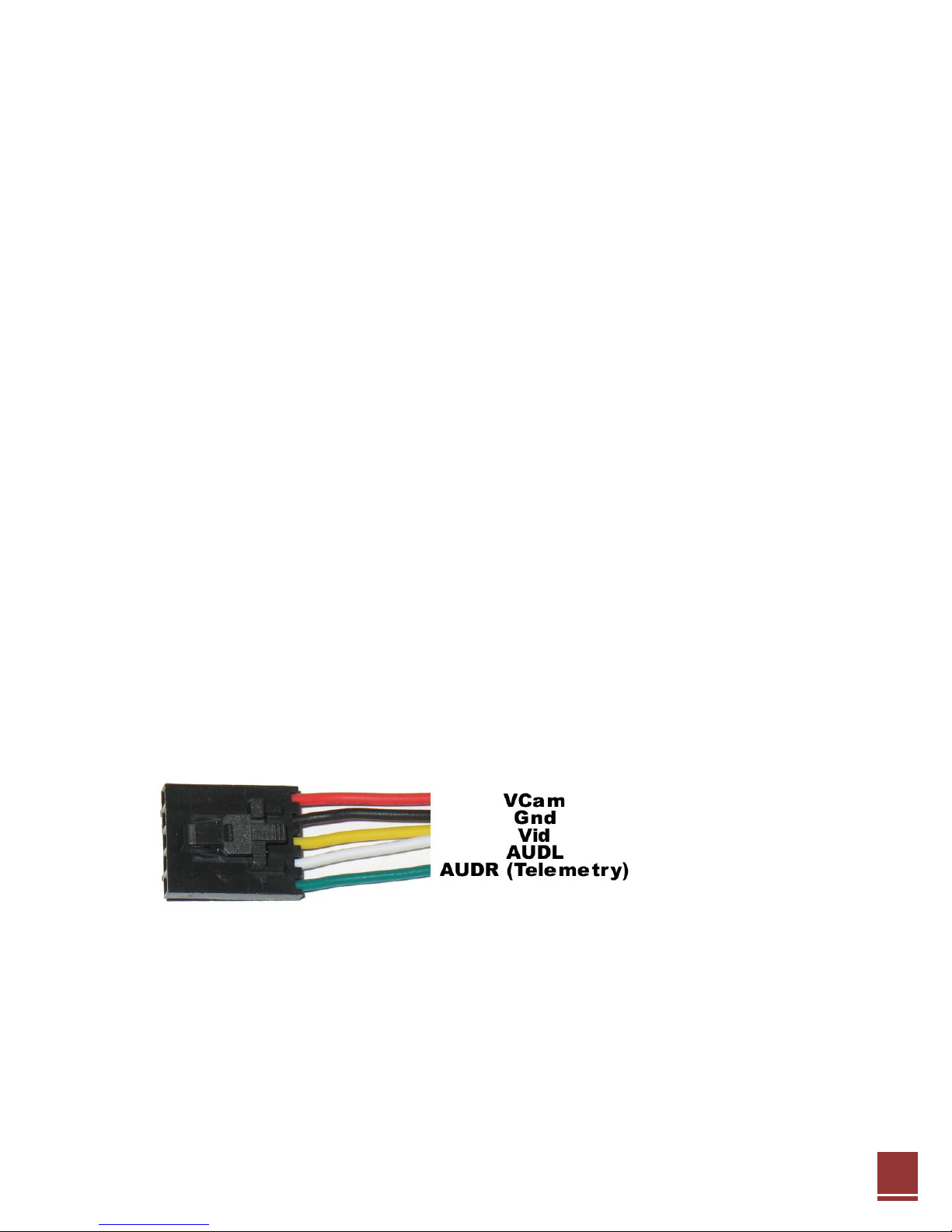
The EzAntennaTracker -Lite module requires the following connections:
1. Audio Input
The audio input is supplied via a 4-Pole, 3.5mm jack, with the same pinout used for other Fat Shark, and
ImmersionRC equipment.
Only the AUDR (Audio, Right), and Ground pins are connected on this connector.
2. Servo Power
Power for the servos, and the EzAntennaTracker module itself,, must be supplied through a standard 3pin servo connector (with only two of the pins used).
Looking at the front of the module, power must be provided through either of the lower two connectors
(these are paralleled, and may be use to daisy-chain power to other devices).
Power the EzAntennaTracker unit the same way you would power a R/C receiver. 5v or 6v depending
upon servo requirements, sourced from either a ‘Rx Battery Pack’, or a 5v/6v BEC.
3. Pan Servo
The upper of the 4 connectors is the Pan Servo connection. Connect any R/C servo to this connector. See
elsewhere in this document for servo recommendations.
4. Tilt servo
The connector below the Pan Servo connector is for the Tilt servo.
Note that the USB connection is currently used primarily for upgrading flash firmware, and may be left
disconnected in normal use.
Page 6
6
2.3. Cabling, Getting the Correct Audio Channel
There are two fundamental types of A/V Tx/Rx equipment being used for FPV, those with a mono audio
link, and those with a stereo link.
The ‘Lawmate’ equipment, and clones, used primarily for law-enforcement, transmits only (relatively
low bandwidth) mono audio (one channel). This equipment will function correctly with the EzOSD
telemetry link, but note that the only audio channel will be dedicated to telemetry, and cannot be used
for an onboard microphone.
The ‘Airwave’ equipment, and clones, provides a high-bandwidth stereo audio link. One of the two
channels may be used for telemetry (generally, the Right-Channel), while the other (Left) may be used
for an onboard microphone.
One of the most common problems experienced when setting up an antenna tracking system is to
ensure the audio is correctly cabled both in the plane (Tx-end), and on the ground (Rx-end).
Additional care must be taken if Lawmate transmitters are used with Airwave receivers (or vice-versa).
These cases will be covered below.
2.4. Transmitter Audio Connection
2.4.1. ImmersionRC/Airwave Transmitter
If ImmersionRC (Airwave) transmitters are used, there are two A/V connectors supplied on the
transmitter board.
One is the 5-pin Molex-SL connector, which is used to interconnect ImmersionRC cameras, Transmitters,
and OSDs. This will be the standard method for connecting the audio channels, and requires no
additional effort (assuming standard cables are used, with all 5 pins connected).
An additional connector is supplied on ImmersionRC transmitters, for future expansion. This is a 5-pin
JST (small white connector), with the same pinout as the larger 5-pin Molex.
Page 7

7
2.4.2. Lawmate Transmitter
For Lawmate transmitters, a 4-pin connector is supplied, with the following pinout. The telemetry signal
from the EzOSD must be routed to the white cable (Audio) .
Yellow Composite Video
White Audio (Mono)
Black Ground
Red +5v/+12v
2.5. Receiver Audio Connection
2.5.1. ImmersionRC/Airwave receivers
ImmersionRC receivers, including the Duo2400, and the Fat Shark RCV922 LCD glasses, all use a standard
4-pole 3.5mm jack. For reasons which are not immediately obvious, manufacturers of equipment using
these connectors do not always follow the same pinout. The 4 most common are shown below:
The pinout used by the ImmersionRC/FatShark equipment is shown, and is shared with other common
consumer equipment (Archos, Creative Labs, Apple, etc.)
When an ImmersionRC transmitter is used, the telemetry signal will appear on the Right audio channel,
pin 3.
Page 8

8
Typically, when a 4-pole 3.5mm cable is terminated with Phono/Cinch/RCA connectors on the other end,
the colors are Yellow for video, Red for Audio-Right, and White for Audio-Left. (Note: This is typical, but
cannot be guaranteed).
2.5.2. Lawmate Receivers
Lawmate receivers use a stereo 3.5mm jack. With the following pinout:
Cables commonly used to interface to Lawmate receivers have a 3.5mm stereo jack on one end, and two
Phono/Cinch/RCA connectors on the other. These connectors are typically Red & White, with audio
emitted on the red connector, and video on the white.
Mixed Equipment
2.6. Lawmate Transmitter, Airwave Receiver
In the case where a lawmate transmitter is coupled to an airwave receiver, for example, the
ImmersionRC Duo 2400, the mono audio from the lawmate transmitter will be emitted on both audio
outputs. Note however that the Right channel (Red connector usually) is generally ‘cleaner’, and
contains less interference from the video channel.
Page 9

9
2.7. Checking, and Debugging Audio Issues
There are two useful tools in the EzAntennaTracker –Lite for debugging audio issues.
The first is the audio level tool. This is accessed by cycling through the status screens using the up/down
buttons. The indicator shows the ‘volume’ detected on the audio right-channel input.
The status in the lower-left corner will show ‘Low’, ‘OK’, or ‘High’, depending upon the suitability of the
audio signal for telemetry use.
The second tool is the Decoder status screen, which shows the number of packets successfully decoded,
along with the bad packet count, and the ratio between good/bad packets.
Note: In most cases, there is no cause for alarm if the pad packet rate is relatively high. The telemetry
protocol used by the EzTelemetry system sends several updates per second, and the antenna tracker
(especially when the plane is a long distance out) requires very few for a successful track.
If the bad packet count is high when the plane is close to the Rx then it may indicate a problem.
2.8. Recording telemetry
Not much to do here either, just ensure that the output from the audio/video receiver is correctly
cabled to the recording device (avoiding swapping the left and right audio channels if possible).
Try to use a fairly high bitrate for recording the audio (DV Camcorder users don’t need to worry, its
plenty high enough).
Page 10

10
2.9. Suitable Pan/Tilt mounts
Figure 3: The SPG785 Pan mount
Figure 2: The DDT500H Tilt mount
Some antenna pan/tilt mounts that have been used successfully with the EzAntennaTracker system are
listed below. The SPG785/DDT500H combination has been used by the designers of the
EzAntennaTracker for several months, and has proven to be a reliable, robust solution.
2.9.1. ServoCity Medium-Duty
SPG785 Pan, 2:1 ratio option (630 degrees)
DDT500H Tilt
This combination works well, and gives a full 360 degree pan rotation with plenty of torque (especially
on the Pan axis) for larger patch antennas.
Figure 4: ServoCity mount with 8dBi 2.4GHz antenna installed
The SPG785 includes the highly recommended HS-785 HB sail winch servo. The specifications for this
servo may be found here: http://www.hitecrcd.com/product_file/file/35/HS-785HB.pdf
This is a high-torque servo, which provides 1260 degrees of rotation, straight out of the box.
2.10. Low cost alternatives
The ‘GWS 125’ 360 degree servo, is a reasonable low-cost alternative for the pan servo, at least for lightweight antennas. This is also sold under the SuperTec brand, as the S125.
Page 11

11
This servo is available from various online retailers, including www.servocity.com in the USA, and
http://www.activerobots.co.uk , or http://www.servoshop.co.uk in the UK.
Note that with any of these 360 degree servos it is highly advisable to support a heavy antenna with an
external bearing, and not rely only on the servo’s output shaft.
2.11. Do I really need a Tilt axis?
Not in all cases. For example, when using the pan/tilt mount for long distance flight, at safe altitudes,
the tilt angle is generally only a few degrees from horizontal, pointing just above the horizon.
In this case, a patch, or yagi antenna, on a pan-only mount, should suffice.
To improve this solution further, use a diversity receiver, with a second omnidirectional antenna, or lowgain patch (with the patch facing straight up). When flying closer to the antenna, the diversity will prefer
the omni, or low-gain patch. When flying long-range the pan-mounted antenna, with its narrower
radiation pattern, will be preferred.
2.12. Servo Splines
One last point on pan servos, there appear to be two common spline sizes used for the output shafts of
standard-size servos. The Futaba, and the Hitec standard. The GWS/SuperTec servo uses a Futaba
standard spline.
Hitec standard-sized servos use a 24-tooth spline, and Futaba, a 25-tooth spline.
ServoCity offers a wide variety of adapters for these standard splines, which are interesting for use in
building an antenna pan/tilt mount.
Page 12

12
Configuration
The setup menu is available by pressing the center menu button. The menu contains a long list (18 at
the current count) of controls, some of which must be configured correctly when setting up the pan/tilt
mount, and some before a flight may start.
Figure 5: Antenna Tracker Controls
2.13. Setup Menu
Once the setup menu is displayed, the Up and Down menu buttons will scroll through the list of
controls. A Carat will show the currently selected control.
To toggle the state of a two-state control, just press the center (Menu) button when the control is
selected with the carat.
To set the value of a numeric field, select the field, press the menu button, and then use the up/down
buttons to adjust the value. A second carat will appear beside the numeric value during its adjustment.
2.13.1. Description of Controls
Each of the controls is described below:
Set Home: Press when the GPS-equipped plane is located beside the antenna. This will give the antenna
tracker one of the references that it needs, before flight.
Note that this occurs automatically the first time that the antenna tracker ‘sees’ 6 satellites or greater
reported by the plane’s GPS. For a more precise fix, wait until the GPS lock is better (9 satellites or
more), and press ‘Set Home’ again.
Calibrate, Bear(ing) Cal(ibration): Press the Calibrate button to teach the antenna tracker the second
reference that it requires, the direction in which the antenna mount is pointing.
See the Calibration section in this manual for a complete description of how this functions.
Page 13

13
Ser vo Set(up): Enable the servo setup control in order to take manual control of the pan and tilt servos.
This is useful during initial setup of the pan/tilt mount, and also when using the same antenna mount
(un-guided) to fly with a plane not equipped with an ImmersionRC telemetry system.
Pan Deg, Tilt Deg:Once servo setup mode is enabled, these controls define the pan and tilt servo angle
respectively.
Pan us/360, Til(t) us/360: These are essentially the relationship between angle, and the width of the
servo pulse required to move the servo to that angle. These controls only need to be setup once, during
the construction of the antenna pan/tilt mount.
See the ‘Setting Up The Servos’ section of this manual for an explanation of how to set these up, along
with example settings for common pan/tilt mounts.
Tilt max, Tilt min, Pan max, Pan min: Use to limit servo movement to avoid mechanical constraints .
Page 14

14
Pan offset, Til(t) offset: Use to correct for mechanical offsets. For example, the tilt offset is used to
define the offset in degrees between ‘zero tilt’ (looking at the horizon), and the servo neutral position.
Pan Rev(erse), Tilt Rev(erse): Allows the pan/tilt axes to be reversed, to adapt to different servo, and
mechanical linkage requirements.
Servo T(e)st: Start a servo test, this will walk the mount around its extremes, in both axes.
Servo Spd: Servo speed, 1 = fastest, 10 = slowest. Normally, the default setting of 1) is appropriate. Use
higher settings only with large, heavy antennas.
Exit: Exit the setup menu, and return to the previously displayed status menu.
Page 15

15
2.14. Setting up the servos
The antenna tracker firmware has several parameters, which are stored in non-volatile memory (i.e.
preserved when not powered up).
These parameters allow the characteristics of the servos, and mount, to be defined, and include:
Pan Reverse no/yes
Tilt Reverse no/yes
Pan us/360 300-2000us in 10us steps
Tilt us/360 200-4000us in 20us steps
Tilt min -90 to +90 degrees in 10 degree steps
Tilt max -90 to +90 degrees in 10 degree steps
To help with the configuration of the mount, a servo setup mode is provided. Once enabled, using the
Servo Setup entry in the menu, the Pan Deg, and Tilt Deg, options may be used to manually move the
servos.
2.14.1. Servo Setup Step #1: Defining the zero position
Use the Servo Setup mode to set both servos to zero degrees (centered). When in this mode,
mechanically adjust the pan/tilt mount configuration until the antenna is pointing ‘straight ahead’, with
zero tilt (pointing at the horizon).
This generally involves simply removing the screw from each servo’s horn, and rotating the horn until
the antenna is in its zero-pan, zero-tilt position;
2.14.2. Servo Setup Step #2: Setting up servo reverses
Once zero has been defined, set each axis to a setting of +20 degrees, and ensure that the servos move
in the correct direction. For Pan, +20 degrees = 20 degrees right of center. For Tilt, +20 degrees = 20
degrees up from level.
If either servo is backwards, change its reverse setting to compensate.
2.14.3. Servo Setup Step #3: Setting up servo gains
Next step is to teach the antenna tracker how many microseconds of servo drive pulse width are
required to rotate through 360 degrees.
To do this, remain in servo setup mode, and set the pan servo manually to a setting of +90 degrees.
Adjust the Pan us/360 control until the pan axis is rotated 90 degrees to the right of center.
Repeat this for the tilt axis.
2.14.4. Servo Setup Step #4: Setting up tilt servo limits
Again, using the Servo Setup mode, manually change the tilt angle to each of its mechanical limits in
turn, then back off by one ‘click’. Note down these values, and enter them into the Tilt min/Tilt max
Page 16

16
controls.
That’s it, the mount should now be setup correctly.
2.15. Example settings
ServoCity pan/tilt mount , SPG785 Pan (2:1, 630 degree option), DDT500H Tilt
Pan Reverse Yes
Tilt Reverse No
Pan us/360 450us
Tilt us/360 4000us
Tilt min 10 degrees (or zero if possible without the tilt servo binding at 0
degrees)
Tilt max 90 degrees
GWS/SuperTec S125 (for pan axis only)
Pan Reverse Yes
Tilt Reverse - - Pan us/360 990us
Tilt us/360 - - -
Tilt min - - Tilt max - - -
Page 17

17
3. Flight
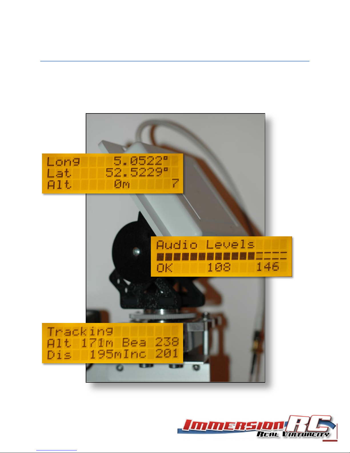
3.1. Status Pages
Four status pages are available, and may be accessed using the up/down buttons while not in the setup
menu.
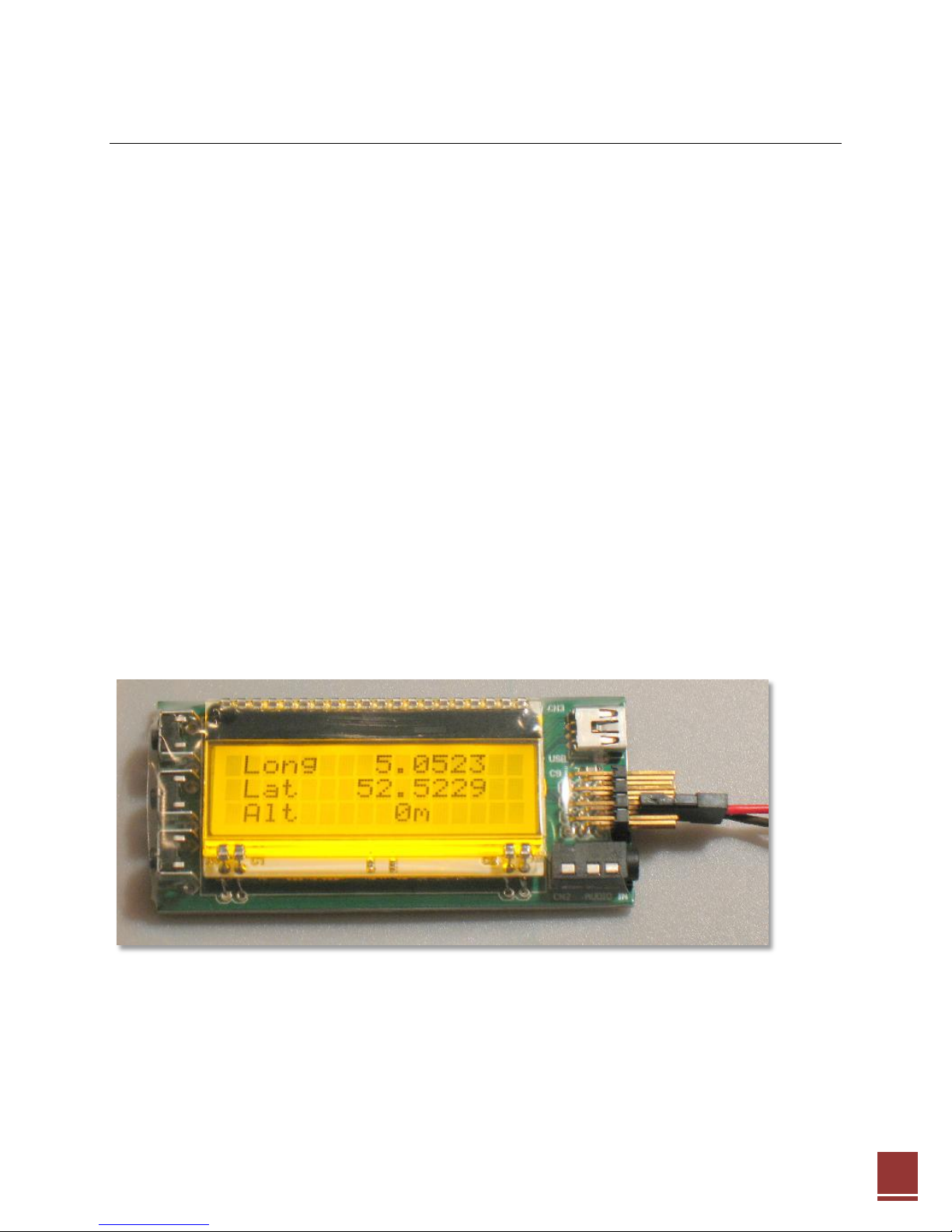
The default page shows the plane’s current (or last-known) GPS coordinates. This includes Longitude,
Latitude, and Altitude (Above Launch Point). The number of satellites currently locked is also shown, in
the lower right corner.
The second page shows the audio levels currently being received, along with an indicator showing ‘Low’,
OK’, or ‘High’.
The Decoder page shows the number telemetry packets decoded, along with the error rate.
The Tracking Page shows the plane’s current altitude (above launch point), distance from the launch
point, and the bearing and inclination of the antenna required to point to the plane.
Page 18

18
3.2. Calibration
The Antenna Tracker has no GPS itself (at least not as a standard feature), nor does it know which way is
north, so it needs some help during setup time to let it know where it is, and which direction it faces.
The antenna tracker should be oriented so that most flying will take place in the natural direction that it
faces (Pan = 0 degrees), to avoid crossing the -180/+180 degree boundary, and therefore avoiding 360
degree complete rotations as the antenna crosses that boundary.
In order to teach it its GPS position, power up the plane, with onboard EzOSD, and wait for it to get a
good satellite fix.
Once it has (and ideally after waiting a couple of minutes for a very precise fix), enter the antenna
tracker’s menu, and select ‘Set Home’.
Next thing to do is teach it which direction is north.
There are a couple of possibilities here:
1) Manually, using a compass.
If a compass is available, then the direction in which the antenna tracking is facing may be directly
entered into the menu, into the Bearing Cal menu item.
As an example, if the zero-position of the antenna tracker points North-West, enter -45 (degrees) into
the Bearing Cal menu. Note that the range of this menu item is -180 thru +180 degrees. Many
compasses are marked from 0 thru 360 degrees, so for values between 180 and 360, just subtract the
value from 360 degrees. E.g. compass reads 320 degrees, 360 – 320 = 40 degrees. Enter this into the
menu.
2) Automatically, using the GPS in the plane
Once the GPS ‘home position’ has been learned, enter the antenna tracker’s menu, and select
‘Calibrate’. The text ‘CAL’ will appear on the display (blinking), and the antenna will move to point to the
center position in both axes (pan = 0 degrees, tilt = 0 degrees).
Walk the plane out 20 or 30 paces (the further the better), directly in the axis of the antenna (antenna is
pointing directly at the plane).
Walk back to the antenna tracker (leaving the plane where it is), and press the center menu button. The
pan (heading) zero position will be stored, and flight can commence!
Page 19

19
Explanation: Why ‘the further the better’?.
When a GPS is powered up, especially in the presence of a high-power video transmitter, the positional
errors can be significant until a large number of satellites have been acquired.
For long distance flight, the antenna positioning accuracy is fairly critical, so the calibration of the
antenna tracker is also just as critical. If the home location of the antenna tracker is stored when the
GPS error is large, and then if the bearing (pan) calibration is performed with the plane close to the
antenna tracker, also with its own GPS error, the bearing calibration error can be quite large.
The further the plane is positioned from the antenna tracker when the bearing calibration is performed,
the less significant this error will be.
3.3.
Tip: If flying often at the same location, mark the position of the antenna mount legs on the ground. The
position of the antenna, and the heading calibration, are stored in non-volatile memory, and will be
restored when power is next applied. This will avoid the need for any ‘home position’, or heading
calibrations each time you fly.
Recorder
Playback
Success
DV Camcorder,
25mbps bitrate, for
audio + video
Apple iPhone video, Audio encoded
to 128kbps, 48kHz sample rate
Approx. 50% lost packets, quite
usable none the less.
DV Camcorder,
25mbps bitrate, for
audio + video
Audio: 256 Kbps, 44,100 Hz, 16 Bit,
Stereo.
Very good, > 95% good packet rate.
4. Replaying recorded telemetry data
Once a flight has been recorded, it may be replayed in order to test the antenna mount (or just to
impress your friends with your NASA-class technology).
When choosing the recording/playback device, and its settings, it is important to remember that the
audio channel which contains the telemetry stream must be recorded at a fairly high bitrate, and sample
rate, in order for reliable decoding to take place.
Audio compression techniques, such as MP3, distort the audio waveform in ways that the human ear
does not detect, but the antenna tracker will be adversely affected.
Some examples of recording/playback devices, and ‘decodability’ are shown below:
5. Frequently Asked Questions
TBD
Page 20

20
 Loading...