

Page 1

*1.034468IE*
Instruction booklet and
warning
IE
ZEUS
24 - 28 kW
Page 2

Our compliments for having chosen a top-quality Immergas product, able to assure well-being and safety for a long period of time. As an Immergas
customer you can also count on a qualied aer-sales service, prepared and updated to guarantee constant eciency of your boiler.
Read the following pages carefully: you will be able to draw useful suggestions regarding the correct use of the appliance, the respect of which, will conrm
your satisfaction for the Immergas product.
Contact our area authorised aer-sales centre as soon as possible to request commissioning. Our technician will verify the correct functioning conditions;
he will perform the necessary calibrations and will demonstrate correct use of the generator.
For any interventions or routine maintenance contact Immergas Authorised Centres: these have original spare parts and boast of specic preparation
directly from the manufacturer.
All Immergas products are protected with packaging suitable for transport. e material must be stored in dry environments and protected from bad weather.
e instruction book is an integral and important part of the product and must be consigned to the user also in the case of transfer of ownership.
It must be kept well and consulted carefully, as all of the warnings supply important indications for safety in the installation, use and maintenance stages.
is instruction booklet contains technical information on how installing Immergas boilers. For other issues related to installation of boilers (i.e.: safety
in work sites, environment protection, injury prevention), comply with the laws in force and technical standards.
Installation and maintenance must be performed in compliance with the regulations in force, according to the manufacturer and professionally qualied
sta, intending sta with specic technical skills in the plant sector.
Improper installation or assembly of Immergas appliance and/or components, accessories, kit and devices can cause unexpected problems to persons,
animals and objects. Read the provided product instructions carefully in order to install the product correctly. Maintenance must be carried out by skilled
technical sta. e Immergas Authorised Aer-sales Service represents a guarantee of qualications and professionalism.
e appliance must only be destined for the use for which it has been expressly declared. Any other use must be considered improper and therefore dangerous.
In the case of errors during installation, running and maintenance due tot he failure to comply with the technical laws in force, standards or the instructions
contained in this book (or however supplied by the manufacturer), the manufacturer is excluded from any contractual and extra-contractual liability for
any damages and the appliance warranty is invalidated.
For further information regarding legislative and statutory provisions relative to the installation of gas heat generators, consult the Immergas site at the
following address: www.immergas.com
Dear Customer,
General recommendations
For the purpose and eect of the CE 90/396 Gas Directive, EMC CE 89/336 Directive, CE 92/42 Boiler Eciency Directives and CE 73/23 Low Voltage
Directive.
e Manufacturer: Immergas S.p.A. v. Cisa Ligure n° 95 42041 Brescello (RE)
DECLARES THAT: the Immergas boiler model: Zeus 24 -28 kW
comply with the above EC Directives
CE DECLARATION OF CONFORMITY
Mauro Guareschi
Research & Development Director
Signature:
INDEX
INSTALLATOR pag. MAINTENANCE pag.
1 Installation of the boiler ...........................3
1.1 Installation recommendation. .................3
1.2 Main dimensions. ......................................3
1.3 Attachments. .............................................. 4
1.4 Remote controls and room
chronothermostats (optional). ................5
1.5 External probe (optional). ........................5
1.6 Installation outside in a partially
protected place. ..........................................6
1.7 Installation indoors. ..................................7
1.8 Fume exhaust to ue/chimney...............12
1.9 Ducting of existing ues. ........................12
1.10 Flues, chimneys and chimney caps. ......12
1.11 System lling. ...........................................13
1.12 Gas system start-up. ................................13
1.13 Boiler start-up (lighting). .......................13
1.14 Domestic hot water boiler device..........13
1.15 Circulation pump. ...................................13
1.16 Kits available on request. ........................13
1.17 Zeus 24-28 kw boiler components. .......14
USER pag.
2 User and maintenance instructions ......15
2.1 Cleaning and maintenance. ...................15
2.2 General warnings. ...................................15
2.3 Control panel. .......................................... 15
2.4 Ignition of the boiler. ..............................16
2.5 Fault and anomaly signals. .....................16
2.6 Boiler shut-down. ....................................16
2.7 Restoring heating system pressure. ....... 17
2.8 Draining the system. ............................... 17
2.9 Anti-freeze protection. ...........................17
2.10 Case cleaning. ..........................................17
2.11 Decommissioning. ..................................17
3 Boiler commissioning (initial check) ...18
3.1 Plumbing layout. .....................................18
3.2 Wiring diagram. ......................................19
3.3 Troubleshooting. .....................................19
3.4 Converting the boiler to other
types of gas. ..............................................20
3.5 Checks following conversion to
another type of gas. .................................20
3.6 Possible adjustments of the gas valve. ..20
3.7 Programming the circuit board.............20
3.8 Automatic slow ignition function
with timed ramp delivery. ......................21
3.9 Chimney sweep “function”. .................... 21
3.10 Pump anti-block function. .....................22
3.11 ree-way anti-block system. ................22
3.12 Radiator anti-freeze function. ...............22
3.13 Electronic card periodical self-check. ..22
3.14 Casing removal. ....................................... 22
3.15 Yearly appliance check and
maintenance. ............................................22
3.16 Variable heat power ................................23
3.17 Combustion parameters. ........................24
3.18 Technical data. .........................................25
Immergas S.p.A. declines all liability due to printing or transcription errors, reserving the right to make any modications to its technical and commercial
documents without forewarning.
Page 3
INSTALLATION
1
OF THE BOILER
1.1 INSTALLATION
RECOMMENDATION.
e Zeus kW boiler has been designed for wall
mounted installation only; they must be used
to heat environments, to produce domestic hot
water and similar purposes.
e installation site and relative Immergas accessories must have suitable characteristics (both
technical and structural), in order to allow (always in safe, eciency and easiness conditions):
- installation (according to the legislation and
technical standards in force);
- maintenance operations (including those
scheduled, periodical, ordinary and special);
- removal (to the outdoors in a place suitable
for loading and transporting appliances and
components) as well as any replacement with
equivalent appliances and/or components.
e wall surface must be smooth, without any
protrusions or recesses enabling access to the
rear part. ey are NOT designed to be installed
on plinths or oors (Fig. 1-1).
By var ying the t ype of installation the
classication of the boiler also varies, precisely:
- B22 type boiler if installed using the relevant
terminal for air intake directly from the room
in which the boiler has been installed.
- C type boiler if installed using concentric pipes
or other types of pipes envisioned for the sealed
chamber boiler for intake of air and expulsion
of fumes.
Only professionally qualied heating/plumbing
technicians are authorised to install Immergas
gas appliances.
Installation must be carried out according to the
standards, current legislation and in compliance
with local technical regulations and the required
technical procedures.
Installation of the Zeus kW boiler when powered
by LPG must comply with the rules regarding
gases with a greater density than air (remember,
as an example, that it is prohibited to install plants
powered with the above-mentioned gas in rooms
where the oor is at a lower quota that the average
external country one).
Before installing the appliance, ensure that it
is delivered in perfect condition; if in doubt,
contact the supplier immediately. Packing
materials (staples, nails, plastic bags, polystyrene
foam, etc.) constitute a hazard and must be kept
out of the reach of children. If the appliance
is installed inside or between cabinets, ensure
sucient space for normal servicing; therefore
it is advisable to leave a clearance of at least 3
cm between the boiler casing and the vertical
sides of the cabinet.
Leave adequate space above the boiler for
possible water and fume removal connections.
At least 60 cm must be le below the boiler
in order to guarantee replacement of the
magnesium anode. Keep all ammable objects
away from the appliance (paper, rags, plastic,
polystyrene, etc.).
Do not place household appliances underneath
the boiler as they could be damaged if the safety
valve intervenes (if not conveyed away by a
discharge funnel), or if there are leaks from the
connections; on the contrary, the manufacturer
cannot be held responsible for any damage
caused to the household appliances.
In the event of malfunctions, faults or incorrect
operation, turn the appliance
o immediately and contact a qualied technician
(e.g. the Immergas Technical Assistance centre,
which has specically trained personnel and
original spare parts). Do not attempt to modify
or repair the appliance alone. Failure to comply
with the above implies personal responsibility
and invalidates the warranty.
• Installation regulations: this boiler can be
installed outside in a partially protected area.
A partially protected location is one in which
the appliance is not exposed to the direct action
of the weather (rain, snow, hail, etc..).
Important: Wall mounting of the boiler must
guarantee stable and ecient support for the
generator.
The plugs supplied are to be used only in
conjunction with the mounting brackets or xing
template to x the appliance to the wall; they only
ensure adequate support if inserted correctly
(according to technical standards) in walls made
of solid or semi-hollow brick or block. In the
case of walls made from hollow brick or block,
partitions with limited static properties, or in any
case walls other than those indicated, a static test
must be carried out to ensure adequate support.
N.B.: the hex head screws supplied in the blister
pack are to be used exclusively to x the relative
mounting bracket to the wall.
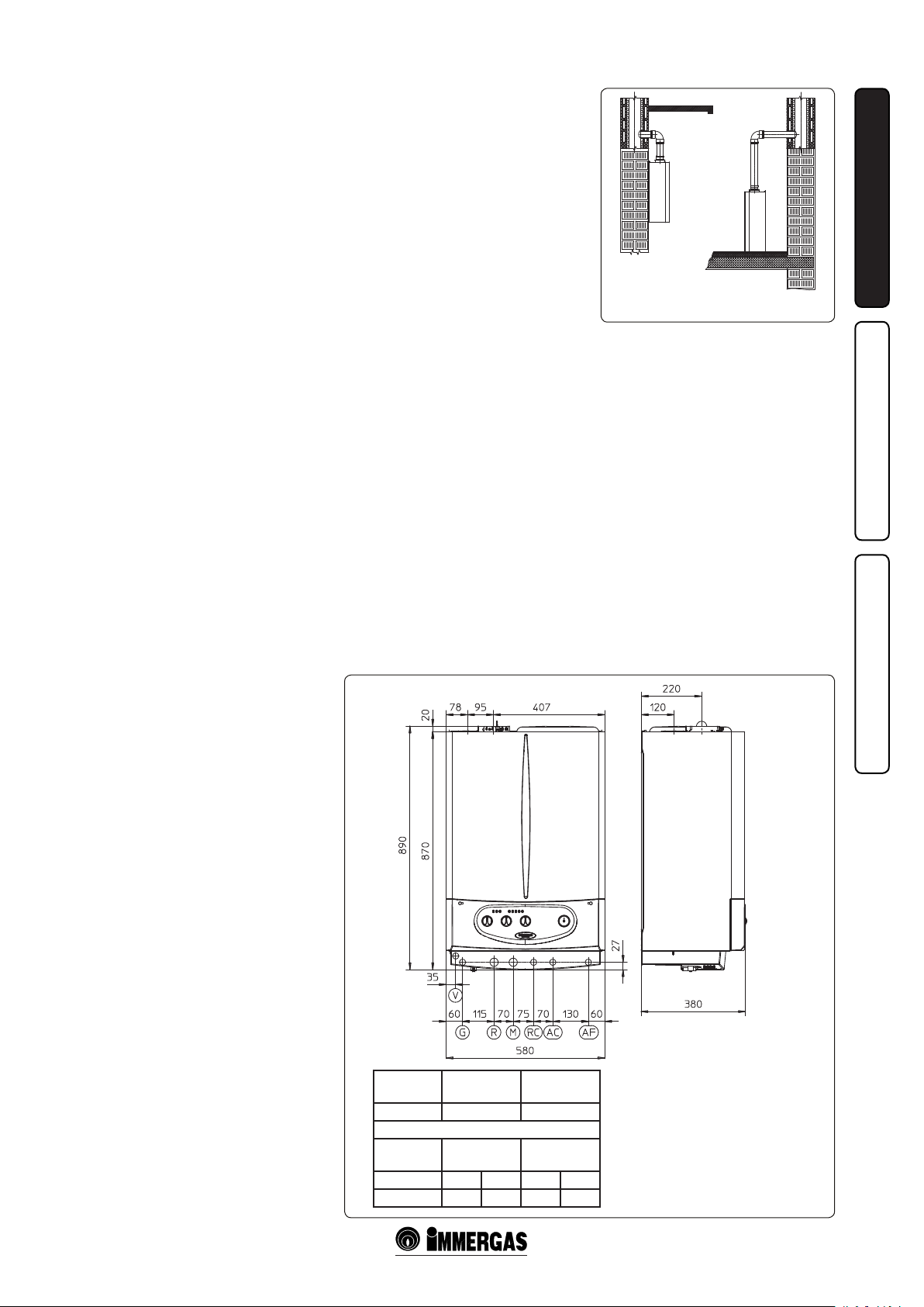
1.2 MAIN DIMENSIONS.
Height
(mm)
890 580 380
GAS PLANT
G R M AC AF
1/2” 3/4” 3/4” 1/2” 1/2”
Width
(mm)
ATTACHMENTS
Depth
(mm)
DOMESTIC
HOT WATER
INSTALLATORUSERMAINTENANCE
YES NO
1-1
ese boilers are used to heat water to below
boiling temperature in atmospheric pressure.
ey must be connected to a heating system and
hot water circuit suited to their performance
and capacity.
Anti-Legionella thermal treatment of the Immergas storage tank (which can be activated
through the specic function present on the set
thermoregulation systems): during this phase,
the water temperature inside the storage tank exceeds 60 °C resulting in burns hazards. Keep this
DHW treatment under control (and inform the
users), to prevent unexpected damage to persons,
animals and objects. If required, a thermostatic
valve must be installed at the DHW outlet to
prevent burns.
1-2
Key:
G - Gas supply
R - System return
M - System delivery
RC - Domestic hot water re-circ.
AC - Domestic hot water outlet
AF - Domestic hot water inlet
V - Electric attachment
3 - IE
Page 4
1.3 ATTACHMENTS.
Gas attachment (II
Our boilers are designed to operate with methane
gas (G20) and LPG. Supply pipes must be the
same as or larger than the 1/2”G boiler tting.
Before connecting the gas line, carefully clean
inside all the fuel feed system pipes to remove any
residue that could impair boiler eciency. Also
make sure the gas corresponds to that for which
the boiler is prepared (see boiler data-plate).
If dierent, the appliance must be converted
INSTALLATORUSERMAINTENANCE
for operation with the other type of gas (see
converting appliance for other gas types). e
dynamic gas supply (methane or LPG) pressure
must also be checked according to the type used
in the boiler, as insucient levels can reduce
generator output and cause malfunctions.
Ensure correct gas cock connection. e gas
supply pipe must be suitably dimensioned
according to current regulations in order to
guarantee correct gas ow to the boiler even
in conditions of max. generator output and
to guarantee appliance efficiency (technical
specifications). The coupling system must
conform to standards.
Combustible gas quality. e appliance has been
designed to operate with gas free of impurities;
otherwise it is advisable to fit special filters
upstream from the appliance to restore the
purity of the gas.
Storage tanks (in case of supply from LPG
depot).
- New LPG storage tanks may contain residual
inert gases (nitrogen) that degrade the mixture
delivered to the appliance casing functioning
anomalies.
- Due to the composition of the LPG mixture,
layering of the mixture components may occur
during the period of storage in the tanks. is
can cause a variation in the heating power of
the mixture delivered to the appliance, with
subsequent change in its performance.
Hydraulic attachment.
Important: In order not to void the warranty
before making the boiler connections, carefully
clean the heating system (pipes, radiators, etc.)
with special pickling or de-scaling products to
remove any deposits that could compromise
correct boiler operation.
Water connections must be made in a rational way
using the couplings on the boiler template. e
boiler safety valve outlet must be connected to a
discharge funnel. Otherwise, the manufacturer
declines any responsibility in case of ooding if
the drain valve cuts in.
Important: to preserve the life and eciency of the
domestic hot water exchanger, it is recommended
to install the “polyphosphate proportioner” kit in
the presence of water whose characteristics can
give rise to scale deposits (in particular, and as
an example, the kit is recommended when water
hardness is higher than 25 French degrees).
category appliance).
2H3+
Electrical connection. e “Zeus kW” boiler
has an IPX4D protection rating for the entire
appliance. Electrical safety of the unit is reached
when it is correctly connected to an ecient
earthing system as specied by current safety
standards.
Imp ortant: Immergas S.p.A. declines any
responsibility for damage or physical injury
caused by failure to connect the boiler to an
ecient earth system or failure to comply with
the reference standards.
Also ensure that the electrical installation
corresponds to maximum absorbed power
specications as shown on the boiler data-plate.
Boilers are supplied complete with an “X” type
power cable without plug. e power supply
cable must be connected to a 230V ±10% / 50Hz
mains supply respecting L-N polarity and earth
connection; , this network must also have a
multi-pole circuit breaker with class III overvoltage category. When replacing the power
supply cable, contact a qualied technician (e.g.
the Immergas Aer-Sales Technical Assistance
Service).
e power cable must be laid as shown. In the
event of mains fuse replacement on the control
card, use a 3.15A quick-blow fuse.
For the main power supply to the appliance,
never use adapters, multiple sockets or extension
leads.
4 - IE
Page 5
Remote Friend controlV2 (CARV2)
On/O digital timer thermostat.
45
58
31
Digital Remote Control
(CRD)
INSTALLATORUSERMAINTENANCE
1-3 1-4
*
1-5 1-6
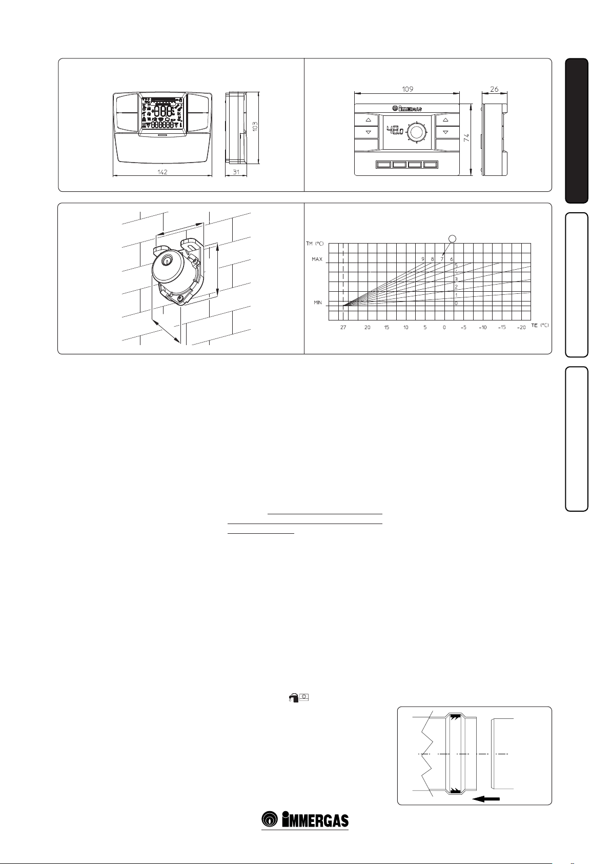
1.4 REMOTE CONTROLS AND ROOM
CHRONOTHERMOSTATS
OPTIONAL.
e boiler is prepared for application of room
chronothermostats and external probe. ese
Immergas components are available as separate
kits to the boiler and are supplied on request.
All Immergas chronothermostats are connected
with 2 wires only. Carefully read the user and
assembly instructions contained in the accessory
kit.
• On/O ff d igita l chronothermost at. The
chronothermostat allows:
- to set two room temperature values: one for
day (comfort temperature) and one for night
(lower temperature);
- to set up to four on/o dierential weekly
programs;
- selecting the required function mode from
the various possible alternatives.
• permanent functioning in comfort temp.
• permanent operation in lower temp.
• permanent function in adjustable anti-freeze
temp.
e chronothermostat is powered by two 1.5V
LR 6 type alkaline batteries;
• ere are two types of Remote Friend ControlV2
(CARV2) (Fig. 1-3) and Digita l Rem ote
Control (CRD) (Fig. 1-4) both with room
chronothermostat functioning. In addition to
the functions described in the previous point,
the Remote Friend ControlV2 enables the
user to control all the important information
regarding operation of the appliance and the
heating system with the opportunity of easily
intervening on the previously set parameters
without having to go to the place where the
appliance is installed. The Remote Friend
ControlV2 panel is provided with self-diagnosis
to display any boiler functioning anomalies.
e climate chronothermostat incorporated in
the remote panel enables the system delivery
temperature to be adjusted to the actual needs
of the room being heated, in order to obtain
the desired room temperature with extreme
precision and therefore with evident saving
in running costs. e chronothermostat is fed
directly by the boiler by means of the same 2
wires used for the transmission of data between
boiler and chronothermostat.
Important: If the system is subdivided into zones
using the relevant kit. the CARV2 must be used
with its climate thermostat function disabled, i.e.
it must be set to On/O mode. e CRD cannot
be used for plants divided into zones.
Electrical connection of the Remote Friend
Cont rolV2 or chronothermo stat On/Off
(Optional). e operations described below must
be performed aer having removed the voltage
from the appliance. The eventual thermostat
or On/Off room chronothermostat must be
connected to terminals 40 and 41 eliminating
jumper X40 (Fig. 3-2). Make sure that the On/
O thermostat contact is of the “clean” type, i.e.
independent of the mains supply, otherwise the
electronic adjustment card would be damaged.
The eventual Remote Friend ControlV2 must
be connected by means of terminals IN+ and
IN- to terminals 42 and 43, eliminating jumper
X40 on the terminal board (in the boiler)
respecting polarity (Fig. 3-2). Connection with
the wrong polarity prevents functioning, but
without damaging the Remote Friend ControlV2.
e boiler works with the parameters set on
the Remote Friend ControlV2 only if the boiler
main selector is turned to Domestic/Remote
Friend ControlV2 ( ). e boiler can only
be connected to one remote control.
Important: If the Remote Friend ControlV2,
Digital Remote Control or any other On/O
chronothermostat is used arrange two separate
lines in compliance with current regulations
regarding electrical systems. Boiler pipes must
never be used to earth the electric or telephone
lines. Ensure elimination of this risk before
making the boiler electrical connections.
1.5 EXTERNAL PROBE OPTIONAL.
• External temperature probe (Fig. 1-5). is
sensor can be connected directly to the boiler
electrical system and allows the max. system
delivery temperature to be automatically
decreased when the outside temperature
increases, in order to adjust the heat supplied
to the system according to the change in
external temperature. The external probe
always operates when connected, regardless of
the presence or type of room chronothermostat
used and can work in combination with the On/
O chronothermostat and the CARV2, (it cannot
be connected to the CRD). e correlation
between system delivery temperature and
outside temperature is determined by the
position of the knob on the boiler control
panel according to the curves shown in the
diagram (Fig. 1-6). e external probe electrical
connection must be made on clamps 38 and 39
on the boiler circuit board (Fig. 3-2).
* (Fig. 1-6) Position of the heating temperature
user adjustment.
1-7
5 - IE
Page 6

1.6 INSTALLATION OUTSIDE IN A
PARTIALLY PROTECTED PLACE.
N.B.: a partially protected location is one in which
the appliance is not exposed to the direct action of
the weather (rain, snow, hail, etc.).
• Conguration type B, open chamber and
forced draught.
The relevant terminal must be used for this
conguration (present in the intake kit for the
installation in question), which must be placed
on the central hole of the boiler (see following
INSTALLATORUSERMAINTENANCE
gure). Air intake takes place directly from the
environment in which the boiler is installed
and fumes are expelled in an individual ue or
directly to the outside.
e boiler in this conguration is classied as
type B22 according to the standards.
With this conguration:
- air intake takes place directly from the
environment in which the boiler is installed
and only functions in permanently ventilated
rooms
- the fumes pipe must be connected to its own
individual ue or channelled directly into the
external atmosphere.
The technical regulations in force must be
respected.
• Fitting the cover kit. (Fig. 1-10) Remove the
two plugs and the seals present from the two
holes to the laterally to the central one.
Install the Ø 80 outlet ange on the central
hole of the boiler, taking care to insert the seal
supplied with the kit and tighten by means
of the screws provided. Install the top cover,
xing it with the screws previously removed
from the lateral plugs. Engage the 90°, Ø 80
bend with the male end (smooth) in the female
end (with lip seal) of the Ø 80 ange until it
stops. Cut the seal in the relative groove at the
desired diameter (Ø 80), run it along the bend
and x it using the sheet steel plate. Insert the
exhaust pipe with the male end (smooth) into
the female side of the 90° bend, Ø 80, making
sure that the relative washer has already been
introduced. This will ensure tightness and
coupling of the elements making up the kit.
Max. length of exhaust ue. e ue pipe (vertical or horizontal) can be extended to a max.
length of 12 m straight route, using insulated
pipes (Fig. 1-28). To prevent problems of fume
condensate in the exhaust pipe Ø 80, due to fume
cooling through the wall, the length of the pipe
must be limited to just 5 m (Fig. 1-25).
• Coupling of extension pipes and elbows. To
install possible coupling extensions on other
fume extraction elements, proceed as follows::
Fit the male end (smooth) of the pipe or elbow
up to the stop on the female end (with lip seals)
of the previously installed element; this will
ensure correct seal and joining of the elements.
Example of installation with direct vertical
terminal in partially protected locatio. When
the vertical terminal for direct discharge of
combustion fumes is used, a minimum gap of
300 mm must be le between the terminal and
the balcony above. e distance A + B (always
with respect to the balcony above), must be equal
to or less than 2000 mm (Fig. 1-9).
• Conguration without cover kit in a partially
protected location (boiler type C).
By leaving the side plugs fitted it is possible
to install the appliance externally without the
cover kit. Installation is carried out using the
horizontal concentric Ø60/100, Ø80/125 and
Ø80/80 separator kits.
VERTICAL TERMINAL KIT
FOR DIRECT DISCHARGE
INTAKE
COVER KIT
1-8
e cover kit include:
N° 1 - Heat moulded cover
N° 1 - Gasket camping plate
N° 1 - Gasket
N° 1 - Gasket clamp
e terminal kit includes:
N° 1 - Seal
N° 1 - Exhaust ange Ø 80
N° 1 - 90° bend Ø 80
N° 1 - Exhaust pipe Ø 80
N° 1 - Ring
1-10 1-11
1-9
6 - IE
Page 7
1.7 INSTALLATION INDOORS.
• Type C conguration, sealed chamber and
forced draught.
Immergas supplies various solutions separately
from the boiler regarding the installation of air
intake terminals and ue extraction; fundamental for boiler operation.
Important: the boiler must only be installed
together with an origin Immergas air intake
and fume extraction system. is system can
be identied by a special distinctive marking
bearing the note: “not for condensing boilers”.
e fume exhaust pipes must not be in contact
with or near ammable materials and must not
cross building structures or walls made of ammable materials.
• Resistance factors and equivalent lengths.
Each flue extraction system component is
designed with a Resistance Factor based on
preliminary tests and specied in the table
below The resistance factor for individual
components does not depend either on the type
of boiler on which it is installed or the actual
dimensions. It is based on the temperature of
uids conveyed through the ducts and therefore
varies according to applications for air intake
or ue exhaust Each single component has a
resistance corresponding to a certain length
in metres of pipe of the same diameter; the
so-called equivalent length, obtained from the
ration between he relative Resistance Factors.
All boilers have an experimentally obtainable
maximum Resistance Factor equal to 100.
The maximum Resistance Factor allowed
corresponds to the resistance encountered with
the maximum allowed pipe length for each
type of Terminal Kit. is information enables
calculations to verify the possibility of various
congurations of ue extraction systems.
Positioning of double lip seals. For correct
positioning of lip seals on elbows and extensions,
follow the assembly direction given in the gure
(Fig. 1-7).
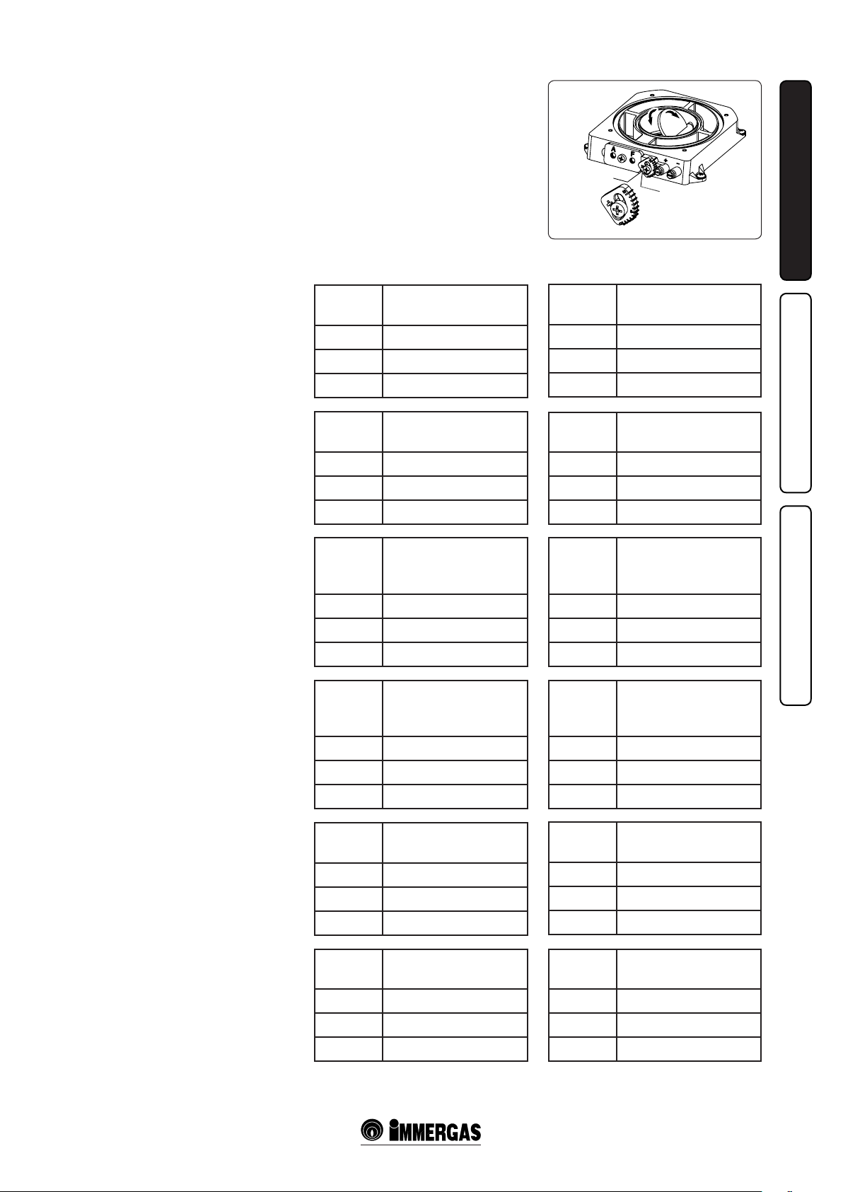
Fumes separ ator adjustment. For correct
functioning of the boiler the fumes separator
positioned on the air/fumes extraction well must
be adjusted (Fig. 1-12).
Adjustment is carried out by loosening the
front retainer screw and moving the indicator
to the correct position, aligning its value to the
horizontal reference (Fig. 1-12). Once adjustment
has been performed, tighten the screw to x the
separator. Appropriate adjustment takes place on
the basis of the type of pipe and its extension: this
calculation can be carried out using the fumes
separator adjustment tables.
Fumes separator adjustments
Zeus 24 kW.
Fumes
separator
3 From 0 to 0,5
5 From 0,5 to 2
10 From 2 to 3
Fumes
separator
3 From 0 to 2,2
5 From 2,2 to 3,7
10 From 3,7 to 4,7
Fumes
separator
3 From 0 to 4
5 From 4 to 26
6 From 26 to 35
Fumes
separator
3 Da 0 to 8
5 Da 8 to 30
6 Da 30 to 40
Fumes
separator
3 From 0 to 0,5
5 From 0,5 to 4,6
10 From 4,6 to 7,4
Duct length in metres
Ø 60/100 horizontal
Duct length in metres
Ø 60/100 vertical
*Duct length in metres
Ø 80 horizontal
With two bends
*Duct length in metres
Ø 80 vertical
without bends
Duct length in metres
Ø 80/125 horizontal
Fumes separator adjustments
Zeus 28 kW.
Fumes
separator
3 From 0 to 0,5
5 From 0,5 to 2
10 From 2 to 3
Fumes
separator
3 From 0 to 2,2
5 From 2,2 to 3,7
10 From 3,7 to 5,7
Fumes
separator
3 From 0 to 2
5 From 2 to 21
7 From 21 to 35
Fumes
separator
3 From 0 to 6
5 From 6 to 25
7 From 25 to 40
Fumes
separator
3 From 0 to 0,5
5 From 0,5 to 4,6
10 From 4,6 to 10,1
Duct length in metres
Ø 60/100 horizontal
Duct length in metres
Ø 60/100 vertical
*Duct length in metres
Ø 80 horizontal
with two bends
*Duct length in metres
Ø 80 vertical
without bends
Duct length in metres
Ø 80/125 horizontal
1-12
INSTALLATORUSERMAINTENANCE
Fumes
separator
3 From 0 to 5,4
5 From 5,4 to 9,5
10 From 9,5 to 12,2
* e values for maximum length are considered
with 1 metre of exhaust pipe and the remaining
on intake.
Duct length in metres
Ø 80/125 vertical
7 - IE
Fumes
separator
3 From 0 to 5,4
5 From 5,4 to 9,5
10 From 9,5 to 15,0
* e values for maximum length are considered
with 1 metre of exhaust pipe and the remaining
on intake.
Duct length in metres
Ø 80/125 vertical
Page 8
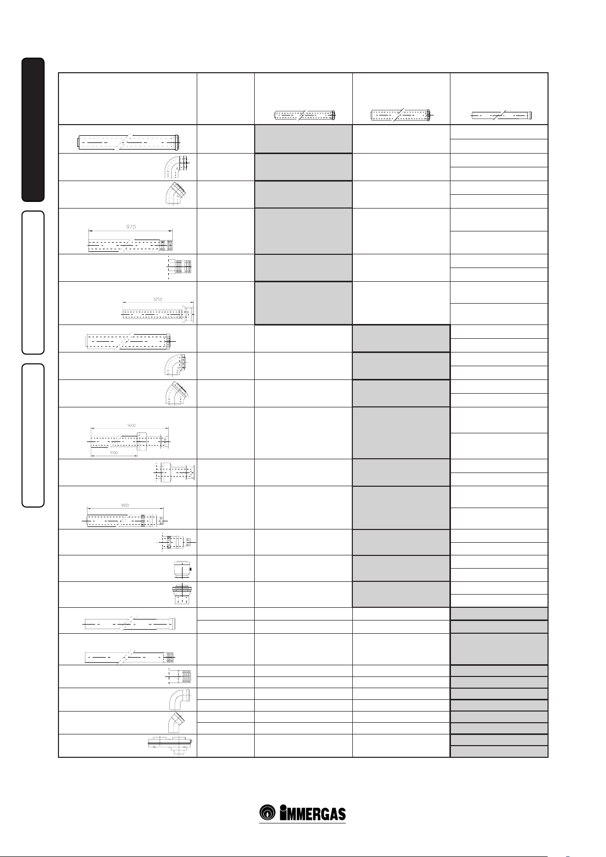
Resistance Factors and Equivalent Lengths Table
Resistance
DUCT TYPE
Factor
(R)
Equivalent length
in meter of concentric pipe
Ø 60/100
Equivalent length
in meter of concentric pipe
Ø 80/125
Equivalent length
in metres of pipe
Ø 80
Concentric pipe Ø 60/100 m 1
90° bend concentric Ø 60/100
INSTALLATORUSERMAINTENANCE
45° bend concentric Ø 60/100
Terminal complete with concentric
horizontal intake-exhaust Ø 60/100
Terminal complete with concentric
horizontal intake-exhaust Ø 60/100
Terminal complete with concentric
vertical intake-exhaust Ø 60/100
Concentric pipe Ø 80/125 m 1
90° bend concentric Ø 80/125
45 bend concentric Ø 80/125
Terminal complete with concentric horizontal intake-exhaust Ø 80/125
Terminal complete with concentric
horizontal intake-exhaust Ø 80/125
Terminal complete with concentric
horizontal intake-exhaust Ø 80/125
Terminal complete with concentric
horizontal intake-exhaust Ø 80/125
Concentric adapter from Ø 60/100
to Ø 80/125 with condensate collector
Concentric adapter from
Ø 60/100 to Ø 80/125
Pipe Ø 80, 1 m (with or without insulation)
Complete pipe terminal Ø 80, 1 m
(with or without insulation)
Intake and
Exhaust 16,5
Intake and
Exhaust 21
Intake and
Exhaust 16,5
Intake and
Exhaust 46
Intake and
Exhaust 32
Intake and
Exhaust 41,7
Intake and
Exhaust 6
Intake and
Exhaust 7,5
Intake and
Exhaust 6
Intake and
Exhaust 33
Intake and
Exhaust 26,5
Intake and
Exhaust 39
Intake and
Exhaust 34
Intake and
Exhaust 13
Intake and
Exhaust 2
Intake 2,3 m 0,1 m 0,4 Intake m 1,0
Exhaust 3 m 0,2 m 0,5 Exhaust m 1,0
Intake 5 m 0,3 m 0,8 Intake m 2,2
m 1 m 2,8
m 1,3 m 3,5
m 1 m 2,8
m 2,8 m 7,6
m 1,9 m 5,3
m 2,5 m 7
m 0,4 m 1,0
m 0,5 m 1,3
m 0,4 m 1,0
m 2,0 m 5,5
m 1,6 m 4,4
m 2,3 m 6,5
m 2,0 m 5,6
m 0,8 m 2,2
m 0,1 m 0,3
Intake m 7,1
Exhaust m 5,5
Intake m 9,1
Exhaust m 7,0
Intake m 7,1
Exhaust m 5,5
Intake m 20
Exhaust m 15
Intake m 14
Exhaust m 10,6
Intake m 18
Exhaust m 14
Intake m 2,6
Exhaust m 2,0
Intake m 3,3
Exhaust m 2,5
Intake m 2,6
Exhaust m 2,0
Intake m 14,3
Exhaust m 11,0
Intake m 11,5
Exhaust m 8,8
Intake m 16,9
Exhaust m 13
Intake m 14,8
Exhaust m 11,3
Intake m 5,6
Exhaust m 4,3
Intake m 0,8
Exhaust m 0,6
Intake terminal Ø 80
Exhaust terminal Ø 80
Bend 90° Ø 80
Bend 45° Ø 80
Split parallel Ø 80
from Ø 60/100 to Ø 80/80
Intake 3 m 0,2 m 0,5 Intake m 1,3
Exhaust 2,5 m 0,1 m 0,4 Exhaust m 0,8
Intake 5 m 0,3 m 0,8 Intake m 2,2
Exhaust 6,5 m 0,4 m 1,1 Exhaust m 2,1
Intake 3 m 0,2 m 0,5 Intake m 1,3
Exhaust 4 m 0,2 m 0,6 Exhaust m 1,3
Intake and
Exhaust 8,8
m 0,5 m 1,5
Intake m 3,8
Exhaust m 2,9
8 - IE
Page 9
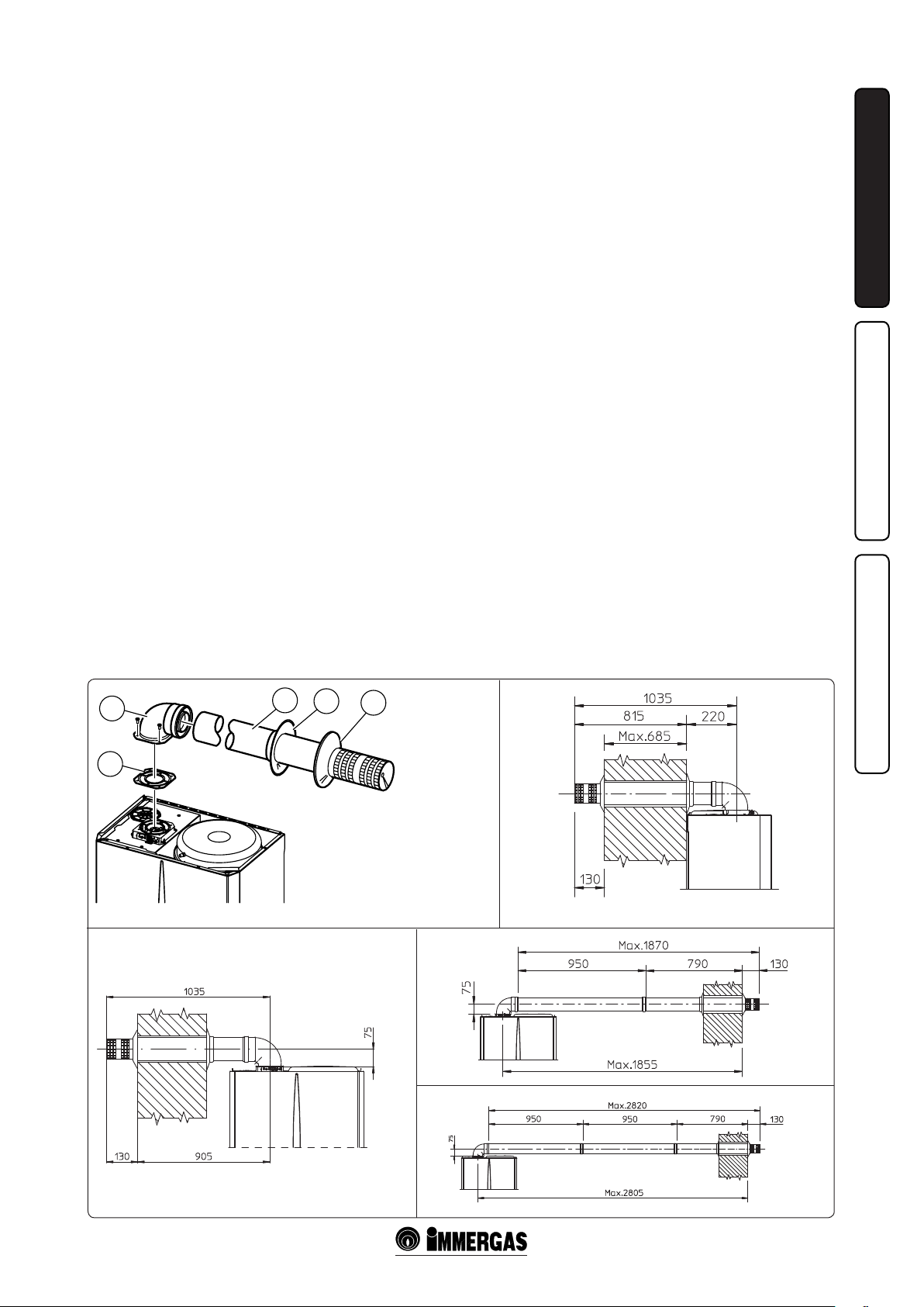
Horizontal intake kits - exhaust Ø60/100. Kit
assembly (Fig. 1-13): install the bend with ange
(2) on the central hole of the boiler inserting the
seal (1) and tighten using the screws present in
the kit. Engage the terminal pipe (3) with the
male side (smooth), into the female side (with lip
seal) of the curve (2) until it stops, making sure
the relevant internal and external rings are tted,
this will ensure hold and joining of the elements
making up the kit.
N.B.: when the boilers are installed in areas where
very rigid temperatures can be reached, a special
anti-freeze kit is available that can be installed as
an alternative to the standard kit.
• Coupling extension pipes and concentric elbows Ø 60/100 snap-t extensions with other
elements of the fume extraction elements
assembly, follows: t the concentric pipe or
elbow with the male on the female section
(with lip seal) to the end stop on the previously
installed element. to ensure sealing eciency
of the coupling.
e Ø 60/100 kit can be installed with the rear,
right side, le side and front outlet.
• Application with rear outlet (Fig. 1-14). e
970 mm pipe length enables routingthrough a
max. thickness 685 mm. Normally the terminal
must be shortened. Calculate the distance by
adding the following: part thickness+ internal
projection + external projection. e minimum
projectionvalues are given in the gure.
• Application with side outlet (Fig. 1-15); Using
the horizontal intake/exhaust kit, without the
special extensions, the maximum distance
between the vertical exhaust axis and the outside wall is 905 mm.
2
3
• Extensions for horizontal kit. e horizontal
intake/exhaust kit Ø 60/100 can be extended
up to a max. horizontal distance of 3000 mm
includingthe terminal with grille and excluding
the concentric bend leaving theboiler. is conguration corresponds to a resistance factor of
100. Inthese cases the special extensions must
be requested.
Connection with 1 extension (Fig. 1-16). Max.
distance between vertical boiler axis and external wall: mm 1855.
Connection with 2 extensions (Fig. 1-17).
Max. distance between vertical boiler axis and
external wall: mm 2805.
Horizontal intake/exhaust kits Ø 80/125. Kit
assembly (Fig. 1-18): install the bend with ange
(2) on the central hole of theboiler inserting the
seal (1) and tighten using the screws in the kit.
Fit the male end (smooth) of the adapter (3) up
to the stop on the female end of the bend (2)
(with lip seal). Fit the male end (smooth) of the
Ø 80/125 concentric terminal pipe (4) up to the
stop on the female end of the adapter (3) (with
lip seals),, making sure the relevant internal and
external rings are tted, this will ensure hold
and joining of the elements making up the kit.
• Coupling extension pipes and concentric
elbows Ø 80/125 snap-fit extensions with
other elements of the fume extraction elements
assembly, follows: t the concentric pipe or
elbow with the male on the female section
(with lip seal) to the end stop on the previously
installed element; this will ensure correct hold
and joining of the elements.
Important: if the exhaust terminal and/or
extension concentric pipe needs shortening,
consider that the internal duct must always
project by 5 mm with respect to the external duct.
4
5
C12
Normally the horizontal intake/exhaust kit Ø
80/125 is used if particularly long extensions
are required; the kit Ø 80/125 can be installed
with the rear, right side, le side or front outlet.
• Extensions for horizontal kit. e horizontal
intake/exhaust kit Ø 80/125 can be extended
up to a a maximum horizontal length of 7300,
including the terminal with grille and excluding
the concentric bend leaving the boiler and the
adapter Ø 60/100 in Ø 80/125 (Fig. 1-19). is
conguration corresponds to a resistance factor
of 100. In this case the special extensions must
be requested.
N.B.: When installing the ducts, a section
clamp with pin must be installed every 3
metres.
• External grill. N.B.: for safety purposes, do not
even temporarily obstruct the boiler intake/
exhaust terminal.
Vertical kit with aluminium tile Ø 80/125. Kit
assembly (Fig. 1-20): install the concentric ange
(2) on the central hole of the boiler inserting the
seal (1) and tighten using the screws in the kit. Fit
the male end (smooth) of the adapter (3) in the
female end of the concentric ange (2). Imitation
aluminium tile installation. replace the tile with
the aluminium sheet (5), shaping it to ensure that
rainwater runs o. Position the xed half-shell
(7) on the aluminium tile and insert the intake/
exhaust pipe (6). Fit the male end (smooth) of the
Ø 80/125 concentric terminal pipe (6) up to the
stop on the female end of the adapter (3) (with
lip seals), making sure that the ring is already
tted (4), this will ensure sealing and joining of
the elements making up the kit.
C12
INSTALLATORUSERMAINTENANCE
1-13
1
e kit includes:
N°1 - Seal (1)
N°1 - Concentric 90° curve (2)
N°1 - Intake/exhaust concentric pipe
Ø60/100 (3)
N°1 - Internal ring (4)
N°1 - External ring (5)
1-14
C12 C12
1-16
C12
1-171-15
9 - IE
Page 10

INSTALLATORUSERMAINTENANCE
1-18
3
2
4
5
6
C12
C12
1
e kit includes:
N°1 - Seal (1)
N°1 - Concentric bend Ø 60/100 (2)
N°1 - Adapter Ø 60/100 for Ø 80/125 (3)
N°1 - Concentric intake/exhaust
terminal Ø 80/125
N°1 - Internal ring (5)
N°1 - External ring (6)
1-19
• Coupling extension pipes and concentric elbows. To install possible coupling extensions
on other fume extraction elements, proceed
as follows: t the male end (smooth) of the
concentric pipe or concentric elbow up to the
stop on the female end (with lip seals) of the
previously installed element; this will ensure
correct hold and joining of the elements.
Caution: if the exhaust terminal and/or extension concentric pipe needs shortening, consider
that the internal duct must always protrude by 5
mm with respect to the external duct.
is specic terminal enables ue exhaust and
air intake in a vertical direction.
N.B.: the vertical kit Ø 80/125 with aluminium
tile enables installation on terraces and roofs with
maximum slope of 45% (24°). e height between
the terminal cap and half-shell (374 mm) must
always be respected.
e vertical kit with this conguration can be
extended up to a maximum of 12200 mm vertical
rectilinear, including the terminal (Fig. 1-21).
is conguration correspondsto a resistance
factor of 100. In this case specic extensions
must be requested.
The terminal Ø 60/100 can also be used for
vertical exhaust, in conjunction with concentric
ange code no. 3.011141 (sold separately). e
height between the terminal cap and half-shell
(374 mm) must always be respected (Fig. 1-21).
e vertical kit with this conguration can be
extended to a max. straight vertical length of 4700
mm, including the terminal (Fig. 1-21).
Separator kit Ø 80/80. e separator kit Ø 80/80,
enables separation of the exhaust ues and air
intake pipes according to the diagram shown in
the gure. (Fig. 1-22). Fumes are expelled from
duct (S). Air is taken in through duct (A) for
combustion. Intake duct (A) can be installed
either on the right or le hand side of the central
exhaust duct (S). Both ducts can be routed in
any direction.
• Assembly of separator kit Ø 80/80. Install the
ange (4) on the central hole of the boiler
inserting the seal (1) and tighten using the
hex and flathead screws supplied with the
kit. Remove the at ange in the lateral hole
with respect to the central one (depending on
installation requirements) and replace with
ange (3) inserting the seal (2) already tted
on the boiler and tighten using the self-tapping
screws supplied. Fit the male end (smooth) of
the bends (5) in the female end of the anges (3
and 4). Fit the male end (smooth) of the intake
terminal (6) up to the stop on the female end
of the bend (5), making sure that the relevant
internal and external rings are tted. Join the
exhaust pipe (9) with the male section (smooth)
in the female section of the bend (5) to the end
stop, ensuring that the internal washer is tted;
this will ensure the sealing eciency of the kit
components.
• Snap t extension pipe ttings and elbows. To
install snap-t extensions with other elements
of the fume extraction elements assembly,
proceed as follows: t the pipe or elbow with
the male section (smooth) in the female section
(with lip seal) to the end stop on the previously
installed element; in this way sealing eciency
of the couplings is assured.
• e gure (Fig. 1-24) shows the conguration
with vertical exhaust and horizontal intake.
• Installation clearances. e gure (Fig. 1-23)
gives the min. installation space dimensions
of the Ø 80/80 separator terminal kit al limit
condition.
• Extensions for separator kit Ø 80/80. e max.
vertical straight length (without bends) usable
for Ø 80 intake and exhaust pipes is 41 metres
of which 40 intake and 1 exhaust. is total
length corresponds to a resistance factor of 100.
e total usable length, obtained by adding the
length of the intake and exhaust pipes Ø 80,
must not exceed the maximum values given
in the following table. If mixed accessories or
components (are used (e.g. changing from a
C32
8
*
*
C32
5
e kit includes:
N°1 - Seal (1)
N°1 - Female concentric ange (2)
7
4
3
2
N°1 - Adapter Ø 60/100 for Ø 80/125 (3)
N°1 - Ring (4)
N°1 - Aluminium tile (5)
N°1 - Intake/Exhaust concentric pipe
6
Ø 80/125 (6)
N°1 - Fixed semi-shell (7)
N°1 - Mobile half-shell (8)
Max 12200 mm
Max 4700 mm
1
1-211-20
10 - IE
Page 11

separator Ø 80/80 to a concentric pipe), the
maximum extension can be calculated by
using a resistance factor for each component
or the the equivalent length. e sumof these
resistance factors must not exceed 100.
• Temperature loss in fume ducts (Fig. 1-25). To
prevent problems of fume condensate in the
exhaust pipe Ø 80, due to fume cooling through
the wall, the length of the pipe must be limited to
just 5 m. If longer distances must be covered,
use Ø 80 pipes with insulation (see insulated
separator kit Ø 80/80 chapter).
Insulated separator kit Ø 80/80. Kit assembly
(Fig. 1-26): install flange (4) on the central
hole of the boiler, tting seal (1), and tighten
with the at-tipped hex screws included in the
kit. Remove the at ange on the lateral hole
(depending on installation requirements) and
replace with ange (3) inserting seal (2) already
tted on the boiler and tighten using the selftapping screws supplied. Insert and slide cap
(6) onto bend (5) from the male side (smooth),
and join bends (5) with the male side (smooth)
in the female side of ange (3). Fit bend (11)
with the male side (smooth) in the female side
of ange (4). Fit the male end (smooth) of the
intake terminal (7) up to the stop on the female
end of the bend (5), making sure you have already
inserted the rings (8 and 9) that ensure correct
installation between pipe and wall, then x the
closing cap (6) on the terminal (7). Join the
exhaust pipe (10) with the male side (smooth) in
the female side of the bend (11) to the end stop,
ensuring that the washer (8) is already inserted
for correct installation between the pipe and ue.
• Coupling of extension pipes and elbows. To
install snap-t extensions with other elements
of the fume exhaust system, proceed as follows:
t the male end (smooth) of the concentric
pipe or concentric elbow up to the stop on the
INSTALLATORUSERMAINTENANCE
7
1-22
9
5
5
6
7
8
C82
C42
S
A
4
1
C52
3
e kit includes:
2
N°1 - Exhaust seal (1)
N°1 - Female intake ange (3)
N°1 - Flange seal (2)
N°1 - Female exhaust ange (4)
N°1 - 90° bend Ø 80 (5)
N°1 - Intake terminal Ø 80 (6)
N°1 - Internal rings (7)
N°1 - External ring (8)
N°1 - Exhaust pipe Ø 80 (9)
1-23
C82
1-24
Max. usable lengths (including intake terminal with grill and two 90° bends)
NON-INSULATED
PIPE
Exhaust (m) Intake (m) Exhaust (m) Intake (m)
1 36,0* 6 29,5*
2 34,5* 7 28,0*
3 33,0* 8 26,5*
4 32,0* 9 25,5*
5 30,5* 10 24,0*
* e air intake pipe can be increased to 2.5 metres if the exhaust bend is
eliminated, 2 metres if the air intake bend is eliminated, and 4.5 metres
eliminating both bends.
11 - IE
1-25
INSULATED
PIPE
11 22,5*
12 21,5*
Page 12

female end (with lip seals) of the previously
installed element; this will ensure correct hold
and joining of the elements.
• Insulation of separator terminal kit. In case
of problems of fume condensate in the
exhaust pipes or on the outside of intake
pipes, Immergas supplies insulated intake and
exhaust pipes on request. Insulation may be
necessary on the exhaust pipe due to excessive
temperature loss of fumes during conveyance.
Insulation may be necessary on the intake pipe
INSTALLATORUSERMAINTENANCE
as the air entering (if very cold) may cause the
outside of the pipe to fall below the dew point
of the environmental air. The figures (Fig.
1-27÷1-28) illustrate dierent applications of
insulated pipes.
Insulated pipes are formed of a Ø 80 internal
concentric pipe and a Ø 125 external pipe with
static air space. It is not technically possible
to start with both Ø 80 elbows insulated, as
clearances will not allow it. However starting
with an insulated elbow is possible by choosing
either the intake or exhaust pipe. When starting
with an insulated intake bend, it must be
inserted onto its ange up to the stop on the
fume exhaust ange, which will ensure that the
two intake and exhaust outlets are at the same
height.
• Temperature loss in insulated fume ducting.
To prevent problems of fume condensate in
the insulated exhaust pipe Ø 80, due to cooling
through the wall, the exhaust pipe length must
be limited to 12 metres. e gure (Fig. 1-28)
illustrates a typical insulation application in
which the intake pipe is short and the exhaust
pipe very long (over 5 m). e entire intake
pipe is insulated to prevent moist air in the
place where the boiler is installed, condensing
in contact with the pipe cooled by air entering
from the outside. The entire exhaust pipe,
except the elbow leaving the splitter, is insulated
to reduce heat loss from the pipe, thus
preventing the formation of fume condensate.
N.B.: When installing the insulated pipes, a
section clamp with pin must be installed every
2 metres.
• Conguration type B, open chamber and
forced draught.
By removing the lateral caps on the sealed
chamber and using the cover kit (optional) air
intake takes place directly from the environment
in which the boiler is installed and the fumes
are expelled in an individual ue or directly to
the outside.
The boiler in this configuration, following
the assembly instructions (Fig. 1-10÷1-11), is
classied as type B.
With this conguration:
- air intake takes place directly from the
environment in which the boiler is installed
and only functions in permanently ventilated
rooms;
- the fumes pipe must be connected to its own
individual ue or channelled directly into the
external atmosphere;
- type B open chamber boilers must not be
installed in places where commercial, artisan
or industrial activities take place, which use
products that may develop volatile vapours
or substances (e.g. acid vapours, glues, paints,
solvents, combustibles, etc.), as well as dusts
(e.g. dust deriving from the working of
wood, coal nes, cement, etc.), which may be
damaging for the components of the appliance
and jeopardise functioning.
When using type B installation conguration
indoors, it is compulsory to install the relative
upper cover kit along with the fumes discharge
kit.
The technical regulations in force must be
respected.
1.8 FUME EXHAUST TO FLUE/CHIMNEY.
Flue exhaust does not necessarily have to be connected
to a branched type traditional. Flue exhaust can be
connected to a special LAS type multiple flue.
Multiple and combine flues must be specially
designed according to the calculation method and
requirements of the standards, by professionally
qualied technical personnel. Chimney or ue
sections for connection of the exhaust pipe must
comply with standard requisites..
1.9 DUCTING OF EXISTING FLUES.
With a specic “ducting system” it is possible to reuse existing ues, chimneys and technical openings
to discharge the boiler fumes.. Ducting requires the
use of ducts declared to be suitable for the purpose
by the manufacturer, following the installation and
user instructions, provided by the manufacturer,
and the requirements of the standards.
1.10 FLUES, CHIMNEYS AND CHIMNEY
CAPS.
The flues, chimneys and chimney caps for the
evacuation of combustion products must be in
compliance with applicable standards.
Positioning the dra terminals. Dra terminals
must:
- be installed on external perimeter walls of the
building;
- be positioned according to the minimum
distances specied in current technical standards.
Fume exhaust of forced draught appliances
in closed open-top environments. In spaces
closed on all sides with open tops (ventilation pits,
courtyards etc.), direct fume exhaust is allowed for
natural or forced draught gas appliances with a
heating power range from 4 to 35 kW, provided the
conditions as per the current technical standards
are respected.
8
10
11
6
5
5
S
4
1
e kit includes (Fig. 1-28):
N°1 - Exhaust seal (1)
N°1 - Flange seal (2)
N°1 - Female intake ange (3)
N°1 - Female exhaust ange (4)
N°1 - 90° bend Ø 80 (5)
N°1 - Pipe closure cap (6)
N°1 - Intake terminal Ø 80 insulated (7)
N°2 - Internal rings (8)
N°1 - External ring (9)
N°1 - Exhaust pipe Ø 80 insulated (10)
N°1 - Concentric 90° curve Ø 80/125 (11)
1-26
3
2
7
C82
8
9
C82
A
1-27
C82
1-28
12 - IE
Page 13

1.11 SYSTEM FILLING.
Once the boiler is connected, proceed with system
lling via the lling valve (Fig. 2-2).
Filling is performed at low speed to ensure release
of air bubbles in the water via the boiler and heating
system vents.
e boiler has a built-in automatic venting valve
on the circulator. Check if the cap is loose. Open the
radiator air vent valves.
Close vent valves only when water is delivered.
Close the lling valve when the boiler pressure gauge
indicates approx. 1.2 bar.
N.B.: During these operations, turn on the
circulating pump at intervals by means of the
main selector switch on the control pane. Vent the
circulation pump by loosening the front cap and
keeping the motor running.
Re-tighten the cap aerwards.
1.12 GAS SYSTEM STARTUP.
To start up the system proceed as follows:
- open windows and doors;
- avoid presence of sparks or naked ames;
- bleed all air from pipelines;
- check that the internal system is properly sealed
according to specications.
1.13 BOILER STARTUP LIGHTING.
For issue of the Declaration of Conformity provided
for by Italian Law, the following must be performed
for boiler start-up:
- check that the internal system is properly sealed
according to specications;
- ensure that the type of gas used corresponds to
boiler settings;
- switch on the boiler and ensure correct ignition;
Total head available to the plant.
- make sure that the gas ow rate and relevant
pressure values comply withthose given in the
manual (Para. 3.16);
- ensure that the safety device is engaged in the event
of gas supply failureand check activation time;
- check activation of the main circuit-breaker
selector upstream from theboiler and on the unit;
- check that the concentric intake/exhaust terminal
(if tted) is not blocked.
e boiler must not be started up in the event of
failure to comply with any of the above.
N.B.: e boiler preliminary check must be carried
out by a qualied technician. e boiler warranty is
valid as of the date of testing. e test certicate and
warranty is issued to the user.
1.14 DOMESTIC HOT WATER BOILER
DEVICE.
e Zeus kW boiler is the accumulation type with
a capacity of 45 litres. It contains a large coiled
stainless steel heat exchanger pipe, which allows to
notably reduce hot water production times. ese
boilers built with stainless steel casing and bottoms,
guarantee long duration. e assembly concepts and
welding (T.I.G.) are implemented to the minimum
detail to ensure maximum reliability.
e lower inspection ange ensures practical control
of the boiler and the coiled heat exchanger and easy
internal cleaning. e domestic water attachments
are found on the ange cover (cold inlet and hot
outlet) and also the magnesium anode holder cap,
including the latter, supplied as standard for internal
protection of the boiler from possible corrosion.
N.B.: every year a skilled technician (e.g. Immergas
Authorised Aer-sales Service), must check the
eciency of the boiler’s Magnesium Anode. e
boiler is prepared for introduction of the domestic
water re-circulation connection.
1.15 CIRCULATION PUMP.
Zeus kW Range boilers are supplied with a built-in
circulation pump with 3-position electric speed
control. e boiler does not operate correctly with
the circulation pump on rst speed. To ensure optimal boiler operation, in the case of new systems
(single pipe and module) it is recommended to
use the circulation pump at maximum speed. e
circulation pump is already tted with a capacitor.
Pump release. If, aer a prolonged period of inactivity, the circulation pump is blocked, unscrew the
front cap and turn the motor sha using a screwdriver. Take great care during this operation to avoid
damage to the motor.
1.16 KITS AVAILABLE ON REQUEST.
• Kit of system shuto valves (on request). e
boiler is designed for installation of system shuto
valves to be placed on delivery and return pipes
of the connection assembly. is kit is particularly
useful for maintenance as it allows the boiler to be
drained separately without having to empty the
entire system.
• System zone Kit (on request). If the heating system
is to be divided into several zones (max. three), in
order to interlock them with separate adjustments
and to keep water ow rate high for each zone,
Immergas supplies zone system kits by request.
• Polyphosphate batching kit (on request). The
polyphosphate dispenser Reduces the formation
of lime-scale and preserves the original heat
exchange and domestic hot production water
conditions. e boiler is prepared for application
of the polyphosphate dispenser kit.
e above kits are supplied complete with instructions for assembly and use.
INSTALLATORUSERMAINTENANCE
Zeus 24 kW
A
Total head (kPa)
B
Capacity (l/h)
Zeus 28 kW
A
Total head (kPa)
B
Capacity (l/h)
A = Total head available to the plant on the third speed (screws tightened by 1.5 revs with
respect to the completely loose adjustment screws)
B = Total head available to the plant on the second speed (screws tightened by 1.5 revs
with respect to the completely loose adjustment screws).
O)
2
Total head (m H
O)
2
Total head (m H
1-29
13 - IE
Page 14

1.17 ZEUS 2428 KW BOILER COMPONENTS.
INSTALLATORUSERMAINTENANCE
Key:
1 - Negative signal pressure point
2 - Positive signal pressure point
3 - Intake points (air A) - (fumes F)
4 - Fumes pressure switch
5 - Fan
6 - Primary heat exchanger
7 - Air bleeding valve
8 - Boiler circulation pump
9 - Gas valve
10 - 3-way valve (motorised)
11 - System ller tap
12 - System expansion tank
13 - Domestic hot water probe
14 - Stainless Steel Boiler
15 - 3 bar safety valve
16 - System emptying tap
17 - 8 bar safety valve
18 - Boiler emptying tap
19 - Sealed chamber
20 - Flue extractor hood
21 - Delivery probe
22 - Combustion chamber
23 - Safety thermostat
24 - Burner
25 - Ignition and detection plugs
1- 30
14 - IE
Page 15

USER AND MAINTENANCE
2
INSTRUCTIONS
2.1 CLEANING AND MAINTENANCE.
Important: the heating plants must undergo
periodical maintenance (regarding this, see in
the section dedicated to the technician, the point
relative to “yearly control and maintenance of the
appliance”) and regular checks of energy eciency
in compliance with national, regional or local
provisions in force.
is ensures that the optimal safety, performance
and operation characteristics of the boiler remain
unchanged over time. We recommend stipulating
a yearly cleaning and maintenance contract with
your zone technician.
2.2 GENERAL WARNINGS.
Never expose the wall-mounted boiler to direct
vapours from a cooking surface.
Use of the boiler by unskilled persons or children
is strictly prohibited.
Do not touch the fumes exhaust terminal (if
present) due to the high temperature it reaches;
For safety purposes, check that the concentric
air intake/ue exhaust terminal (if tted), is not
blocked.
If temporary shutdown of the boiler is required,
proceed as follows:
a) drain the heating system if anti-freeze is not
used;
b) shut-o all electrical, water and gas supplies.
In the case of work or maintenance to structures
located in the vicinity of ducting or devices for
ue extraction and relative accessories, switch o
the appliance and on completion of operations
ensure that a qualied technician checks eciency
of the ducting or other devices. Never clean
the appliance or connected parts with easily
ammable substances. Never leave containers or
ammable substances in the same environment
as the appliance.
• Caution: the use of components involving use
of electrical power requires some fundamental
rules to be observed:
- do not touch the appliance with wet or moist
parts of the body; do not touch when barefoot.
- never pull electrical cables or leave the appliance
exposed to atmospheric agents (rain, sunlight,
etc.);
- the appliance power cable must not be replaced
by the user;
- in the event of damage to the cable, switch o
the appliance and contact exclusively qualied
personnel for replacement;
- if the appliance is not to be used for a certain
period, disconnect the main power switch..
INSTALLATORUSERMAINTENANCE
2.3 CONTROL PANEL.
2-1
Key:
1 - Flame presence LED
2 - Domestic hot water LED
3 - Heating function LED
4 - Temperature LED – Insucient
circulation anomaly
5 - Temperature LED – Delivery probe
anomaly
6 - Temperature LED – ignition block
7 - Temperature LED – Over-temperature
block
8 - Temperature LED – Fumes pressure
switch anomaly
9 - Stand-by-Domestic water / Remote
Control - Domestic water and HeatingReset Selector switch
10 - Domestic hot water temperature
selector switch
11 - Heating water temperature selector
switch
12 - Boiler manometer
15 - IE
Page 16

2.4 IGNITION OF THE BOILER.
Before ignition make sure the heating system is
lled with water and that the manometer (12)
indicates a pressure of 1 - 1.2 bar.
- Open the gas cock upstream from the boiler.
- Turn the master switch (9) taking it to the
Domestic/Remote Friend ControlV2 (CARV2) (
) or Domestic Hot Water ( ) position.
N.B.: once the main selector switch has been
placed (9) on one of these positions, the presence
of voltage is indicated by the switch-on with a
INSTALLATORUSERMAINTENANCE
xed light of one of the LEDS from 4 to 8, which
indicate the temperature of the output water from
the main heat exchanger.
Important: lashing of one of the LEDs from 4 to
8 indicates that there is an anomaly present, refer
to the successive paragraph.
Functioning of the boiler in domestic water mode
and in heating mode is indicated respectively by
the switch-on of LED 2 or LED 3 with a xed light
(in absence of remote controls).
• Operation with Remote Friend Cont rolV2
(Optional). With selector switch (9) in position
( ) Remote Control connected to the boiler
selector switches (10) and (11) excluded. e
boiler adjustment parameters are set from the
control panel of the Remote Friend ControlV2.
Connection tot he Remote Control is indicated
by the contemporary xed switch-on of LEDs 2
and 3 ( ). Also in the presence of Remote
Control the indications of the temperature and
any faults are maintained on the control panel.
• Operation without Remote Control. With the
selector switch (9) in position ( ) the
heating adjustment selector switch(4) is cut out,
the domestic hot water temperature is regulated
by selector switch (10). With the selector switch
in position ( ) the heating adjustment
selector switch (11) is used to regulate the
temperature of radiators, while selector (10)
continues to be used for domestic hot water. Turn
the selector switches in a clockwise direction
to increase the temperature and in an anticlockwise direction to decrease it.
Fr om this mome nt the b oil er fun ctio ns
automatically. With no demand for heat (heating
or domestic hot water production) the boiler goes
to “standby” function, equivalent to the boiler
being powered without presence of ame (LED
corresponding to the ignited boiler temperature).
Each time the boiler lights up, the relative ame
present symbol is displayed by the green LED
1 ( ).
N.B.: the boiler may start-up automatically if the
anti-freeze function is activated.
2.5 FAULT AND ANOMALY SIGNALS.
The Zeus kW boiler signals ant anomaly by
ashing of one of the LEDs from 4 to 8 or LEDs 1
and 2 coupled to LED 7. On any remote controls,
the error code will be displayed using a numerical
code preceeded or folowed by the letter E (e.g.
CARV2 = Exx, CRD = xxE)
Anomaly signalled
Boiling device probe
anomaly
Insucent
circulation
Delivery probe
anomaly
Ignition
block
Safety thermostat block
(over-temperature)
Fumes pressure switch
anomaly
Contacts resistance
block
Parasite ame block
Loss of remote control
communication
Flashing
LED
LED 2 (
LED 4 (
LED 5 (
LED 6 (
LED 7 (
LED 8 (
LEDs 2 (
and 7 ( )
contempora-
ry ashing
LEDs 1 (
and 7 ( )
contempo-
rary
ashing
LEDs 2 and
3 alterna-
ting ashing
(
)
)
) 05
)
)
) 11
)
)
)
Remote
display
12
27
01
02
04
20
31
Boiling device probe anomaly. If the card detects
an anomaly on the boiler NTC probe, the boiler
does not start-up in domestic water mode however,
functioning in heating mode; a skilled technician
must be called (e.g. Immergas Aer-sales Service).
Insucient water circulation. is occurs if there
is overheating in the boiler due to insucient water
circulating in the primary circuit; thecauses can be:
- low circulation; check that no shuto devices are
closed on the heating circuit and that the system
is free of air (deaerated);
- circulating pump blocked; free the circulating
pump.
If this phenomenon occurs frequently, contact a
qualied technician for assistance (e.g. Immergas
Technical Services Centre).
Delivery probe anomaly. If the board detects an
anomaly on the system NTC delivery probe (code
05) the boiler will not start; contact a qualied
technician for assistance (e.g. Immergas Technical
Services Centre).
Ignition block. e boiler lights up with each
demand for room heating or hot water production.
If this does not occur within 10 seconds, the
boiler remains in stand-by for 30 seconds, try
again and if the second attempt fails it goes into
“ignition block” (ashing LED 6). To eliminate
“ignition block” the main selector switch (9) must
be turned to the Rest position. e Anomaly can
be reset 5 times consecutively, aer which the
function in inhibited for at least one hour. One
attempt is gained every hour for a maximum of
5 attempts. By switching the appliance on and o
the 5 attempts are re-acquired. On commissioning
or aer extended inactivity it may be necessary to
eliminate the “ignition block”. If this phenomenon
occurs frequently, contact a qualied technician
for assistance (e.g. Immergas Aer-sales Service).
Safety thermostat block (over-temperature).
During operation, if a fault causes excessive
overheating internally, in the exhaust, or an
anomaly occurs in the flamecontrol section,
an over-temperature block is triggered in the
boiler (LED 7 ashing). To eliminate the “overtemperature block”, turn the main selector switch
(2)temporarily to the Reset position. If this
phenomenon occurs frequently, contact a qualied
technician for assistance (e.g. Immergas Technical
Services Centre).
Fume pressure switch fault. is occurs if the
intake or exhaust pipes are blocked or in case of
a fan fault. If normal conditions are restored the
boiler restarts without having to be reset. If this
anomaly persists, contact a qualied technician
for assistance (e.g. Immergas Aer-Sales Service).
Contacts resistance block. is occurs in the
case of faults to the safety thermostat overtemperature). The boiler does not start and a
technician must be called (e.g. Immergas AerSales Service).
Parasite ame block. is occurs in case of a leak
on the detection circuit or anomaly in the ame
control unit. e boiler does not start. A qualied
technician must be called (e.g. Immergas AerSales Service).
Loss of remote control communicaton. is
occurs if an incompatible remote control is
connected, or if communication between the
boiler and the CARV2 or CRD is lost. Try the
connection procedure again by turning the boiler
o and turning the selector switch (9) to position
( ). If the CARV2 is still not detected on restarting the boiler will switch to local operating
mode, i.e. using the controls on the boiler itself.
If this phenomenon occurs frequently, contact a
qualied technician for assistance (e.g. Immergas
Technical Services Centre).
Signalling and diagnostics - Display on Remote
Friend ControlV2 screen (optional). During
normal boiler operation the room temperature
value is displayed on the Remote Friend ControlV2
(CARV2 or CRD) screen; in case of malfunction or
anomaly, the temperature value is replaced by the
relative error code given in the table (Para. 2-5).
Important: if the boiler is set in stand-by “ ”
the “CON” connection error symbol will appear
on the CARV2 and error code “31E” on the CRD.
e remote controls are powered constantly so as
not to loose the memorised programs.
2.6 BOILER SHUTDOWN.
Disconnect the main selector switch (9) taking it to
position “ ” (LEDs from 1 to 8 o), disconnect
the external omni-polar switch to the boiler and
close the gas cock upstream from the appliance.
Never leave the boiler switched on if le unused
for prolonged periods.
16 - IE
Page 17

2.7 RESTORING HEATING SYSTEM
PRESSURE.
Periodically check the system water pressure.
e boiler pressure gauge should read a pressure
between 1 and 1.2 bar.
If the pressure falls below 1 bar (with the circuit cool)
restore normal pressure via the valve located at the
bottom of the boiler (Fig. 2-2).
N.B.: close the valve aerwards.
If pressure values reach around 3 bar the safety
valve may be activated.
In this case contact a professional technician for
assistance.
In the event of frequent pressure drops, contact
qualified staff for assistance to eliminate the
possible system leakage.
2.8 DRAINING THE SYSTEM.
To drain the boiler, use the special drain cock
(Fig. 2-2).
Before draining, ensure that the lling cock is
closed.
2.9 ANTIFREEZE PROTECTION.
The boiler comes standard with an antifreeze
function that activates the pump and burner when
the system water temperature in the boiler falls
below 4°C and stops once it exceeds 42°C. e
antifreeze function is guaranteed if the boiler is
fully operative and not in “block” status, and is
electrically powered. To avoid keeping the system
switched on in case of a prolonged absence, the
system must be drained completely or antifreeze
substances added to the heating system water.
In both cases the boiler domestic water circuit
must be drained. In systems that are drained
frequently, lling must be carried out with suitably
treated water to eliminate hardness that can cause
lime-scale.
N.B.: if the boiler is installed in places where the
temperature falls below 0°C the domestic water
and heating attachment pipes must be insulated.
INSTALLATORUSERMAINTENANCE
2.10 CASE CLEANING.
Use damp cloths and neutral detergent to clean
the boiler casing. Never use abrasive or powder
detergents.
2.11 DECOMMISSIONING.
In the event of permanent shutdown of the boiler,
contact professional personnel for the procedures
and ensure that the electrical, water and gas supply
lines are shut o and disconnected.
5
4
BOTTOM VIEW
1 - Boiler drain cock
1
2 - Domestic water inlet cock
3 - Gas cock
4 - System drain cock
5 - System lling valve
23
2-2
17 - IE
Page 18

BOILER COMMISSIONING
3
INITIAL CHECK
To commission the boiler:
- ensure that the declaration of conformity of
installation is supplied with the appliance;
- ensure that the type of gas used corresponds to
boiler settings;
- check connection to a 230V-50Hz power
mains, correct L-N polarity and the earthing
connection;
INSTALLATORUSERMAINTENANCE
- make sure the heating system is lled with
water and that the manometer indicates a
pressure of 1 - 1.2 bar;
- make sure the air valve cap is open and that the
system is well deaerated;
- switch the boiler on and ensure correct ignition;
- make sure the gas maximum, medium and
minimum flow rate and pressure values
correspond to those given in the handbook
(Para. 3.16);
3.1 PLUMBING LAYOUT.
- check activation of the safety device in the event
of no gas, as well as the relative activation time;
- check activation of the master switch located
upstream from the boiler and in the boiler;
- check that the intake and/or exhaust terminals
are not blocked;
- check activation of the “no air” safety pressure
switch;
- ensure activation of all adjustment devices;
- seal the gas ow rate regulation devices (if
settings are modied);
- ensure production of hot domestic water;
- ensure sealing eciency of water circuits;
- check ventilation and/or aeration of the
installation room where provided.
If any checks/inspection give negative results, do
not start the boiler.
Key:
1 - Gas valve
2 - Stainless steel coil for boiler
3 - Magnesium anode
4 - Stainless steel boiler
5 - Air bleeding valve
6 - Burner
7 - Combustion chamber
8 - Primary heat exchanger
9 - Fumes hood
10 - Fan
11 - Fumes pressure switch
12 - Sealed chamber
13 - Delivery probe
14 - Safety thermostat
15 - System expansion tank
16 - Boiler circulating pump
17 - Adjustable by-pass
18 - System drain cock
19 - 3-way valve (motorised)
20 - Domestic water probe
21 - 3 bar safety valve
22 - System lling cock
23 - 8 bar safety valve
24 - Cold water inlet non-return valve
25 - Boiler drain cock
G - Gas supply
AC - Domestic hot water outlet
AF - Domestic cold water inlet
R - System return
M - System delivery
18 - IE
3-1
Page 19

3.2 WIRING DIAGRAM.
3
7
6
1
2
4
8
Key:
A5 - CARV2 interface card
B1 - Delivery probe
B2 - Domestic water probe
B4 - External probe (optional)
CARV2 - Remote Friend Control
V2
(optional)
CRD - Remote digital control (optional)
E1 - Ignition plugs
E2 - Igniter sensor
5
9
9
E4 - Safety thermostat
F1 - Neutral fuse
F2 - Line fuse
M1 - Boiler circulating pump
M20 - Fan
M30 - 3-way valve (motorised)
R5 - Domestic water temp. trimmer
R6 - Heating temp. trimmer
R10 - Main selector switch
14
15
INSTALLATORUSERMAINTENANCE
7
8
7
9
11
12
10
12
11
10
9
13
13
8
7
8
S6 - Fumes pressure switch
S8 - Gas type selector
S20 - Environment thermostat (optional)
T2 - Switch-on transformer
X40 - Environment thermostat jumper
Y1 - Gas valve
Y2 - Gas valve modulator
1 - Primary
2 - Secondary
3 - 230 Vac 50Hz Power supply
4 - 230 Vac 50Hz max 2° aux. output
5 - Card area
6 - Yellow/Green
7 - Blue
8 - Brown
9 - White
10 - Green
11 - Red
12 - Black
13 - Grey
14 - Heating
15 - Domestic water
9
12
11
3-2
Remote controls: the boiler is designed to use
the Remote Friend ControlV2 (CARV2), or as an
alternative to the Digital Remote Control (CRD)
which must be connected to clamps 42 and 43 of
connector X9 for the CARV2 (respecting polarity)
and clamps 40 and41 of connector X9 for the CRD
on the circuit board and in both cases eliminating
X40.
Environment thermostat (alternative to the CRD):
the boiler is designed to use the Room ermostat
(S20). Connect it to clamps 40 – eliminating
jumper X40.
Connector X12 (RS 232) is used for automatic
inspection for connect ion to the personal
computer.
3.3 TROUBLESHOOTING.
N.B.: Maintenance must be carried out by a
qualified technician (e.g. Immergas Technical
Assistance Service).
- Smell of gas. Caused by leakage from gas circuit
pipelines. Check sealing eciency of gas intake
circuit.
- e fan works but ignition discharge does not
occur on the burner train. e fan may start but
the safety air pressure switch does not change the
contact. Make sure:
1) the intake/exhaust duct is not too long (over
allowed length).
2) the intake/exhaust duct is not partially blocked
(on the exhaust or intake side).
3) the diaphragm on the fume exhaust is adequate
for the length of the intake/exhaust ducts.
4) the fan power supply voltage is not less than
196 V.
- Irregular combustion (red or yellow flame).
is may be caused by a dirty burner, incorrect
combustion paramet ers, i nta ke-exhaust
terminal not correctly installed. Clean the above
components and ensure correct installation of
the terminal.
- Frequent activation of the temperature overload
thermostat. is may be caused by lack of water
in the boiler, insucient water circulation in
the circuit or a blocked circulator. Check via the
pressure gauge that values are within admissible
limits. Check that radiator valves are not all
closed.
- Presence of air in the system. Check opening of
the special air bleeding cap (Fig. 1-30). Make
sure the system pressure and expansion tank
pre-charge values are within the set limits; the
pre-charge value for the expansion tank must be
1.0 bar, and system pressure between 1 and 1.2
bar.
- Ignition block: (Para. 2.5).
- Domestic water probe broken. e boiler does
not have to be emptied in order to replace the
domestic water probe as the probe is not in direct
contact with the domestic hot water present in
the boiler.
19 - IE
Page 20

SIT 845 gas valve
Key:
INSTALLATORUSERMAINTENANCE
1 - Coil
2 - Minimum power adjustment screws
3 - Maximum power adjustment nut
4 - Gas valve outlet pressure point
5 - Gas valve inlet pressure point
6 - Protection hood
Zeus 24-28 kW circuit board
10 - Line fuse 3.15AF
11 - Neutral fuse 3.15AF
12 - Main selector switch
13 - Domestic water temperature trimmer
14 - RS232 computer interface
15 - Heating temperature trimmer
16 - METHANE L.P.G. gas type selector
3.4 CONVERTING THE BOILER TO
OTHER TYPES OF GAS.
If the boiler has to be converted to a dierent gas
type to that specied on the data-plate, request
the relative conversion kit for quick and easy
conversion.
Boiler conversion must be carried out by a
qualified technician (e.g. Immergas Technical
Assistance Service).
To convert to another type of gas the following
operations are required:
- remove the voltage from the appliance;
- replace the main burner injectors, making sure
to insert the special seal rings supplied in the kit,
between the gas manifold and the injectors;
- move jumper 16 (Fig. 3-4) into the correct
position for the type of gas in use (Methane or
L.P.G.);
- to access adjustments on the circuit board the
cover must be removed from the dashboard by
loosening the rear screw fasteners;
- apply voltage to the appliance;
- adjust the boiler maximum heat power;
- adjust the boiler minimum heat power;
- adjust (eventually) the heating power;
- seal the gas ow rate devices (if adjusted);
- aer completing conversion, apply the sticker,
present in the conversion kit, near the data-plate.
Using an indelible marker pen, cancel the data
relative to the old type of gas.
ese adjustments must be made with reference
to the type of gas used, following that given in the
table (Para. 3.16).
4
1
5
3.5 CHECKS FOLLOWING CONVERSION
TO ANOTHER TYPE OF GAS.
Aer making sure that conversion was carried out
with a nozzle of suitable diameter for the type of
gas used and the settings are made at the correct
pressure, check that:
- there is no flame return in the combustion
chamber;
- the burner ame is not too high or low and that
it is stable (does not detach from burner);
- the pressure testers used for calibration are
perfectly closed and there are no leaks from the
gas circuit.
N.B.: All boiler adjustment operations must
be carried out by a qualified technician (e.g.
Immergas Assistance Service). Burner adjustment
must be carried out using a dierential “U” or
digital type pressure gauge, connected to the
pressure point located above the sealed chamber
(part. 2 Fig. 1-30) and the gas valve pressure outlet
(part. 4 Fig. 3-3), keeping to the pressure value
given in the tables (Para. 3.16) according to the
type of gas for which the boiler is prepared.
3.6 POSSIBLE ADJUSTMENTS OF THE
GAS VALVE.
• Adjustment of boiler nominal heat output (Fig.
3-3).
- Turn the domestic hot water selector knob (10
Fig. 2-1) to the maximum functioning position;
- open the domestic hot water cock in order to
prevent modulation intervention;
- adjust the boiler nominal power on the brass nut
(3), keeping to the maximum pressure values
stated in the tables (Para. 3.16) depending on
the type of gas;
- by turning in a clockwise direction the heating
potential increases and in an anti-clockwise
direction it decreases.
• Adjust the boiler minimum thermal input (Fig.
3-3).
N.B.: only proceed aer having calibrated the
nominal pressure.
Adjustment of the minimum thermal input is
obtained by operating on the cross plastic screws
3
2
6
(2) on the gas valve maintaining the brass nut
blocked (3);
- disconnect the power supply t the modulating
reel (just disconnect a faston); By turning the
screw in a clockwise direction, the pressure
increases, in an anti-clockwise direction it
decreases. On completion of calibration, re-apply
the power supply tot he modulating reel. e
pressure to which the boiler minimum power
must be adjusted, must not be lower than that
3-3
stated in the tables (Para. 3.16) depending on the
type of gas.
N.B.: to adjust the gas valve, remove the plastic
cap (6); aer adjusting, ret the cap and screw.
3.7 PROGRAMMING THE CIRCUIT
BOARD.
The Zeus kW boiler is prepared for possible
programming of several operation parameters.
By modifying these parameters as described
below, the boiler can be adapted according to
specic needs.
To access the programming phase, proceed as
follows: position the main selector switch on
Reset for a period of time between 15 and 20
3-4
seconds (aer about 10 sec. LEDs 2 and 3 will
start to ash at the same time. Wait for this to
end and re-position the main selector switch on
domestic water and heating). At his point, reposition the main selector switch on domestic
water-heating ( ).
When the programming phase has been activated,
enter the rst level where it is possible to choose
the parameter to be set.
e latter is indicated by the fast ashing of one
of the LEDs between 1 and 8 (Fig. 2-1).
Selection is made by turning the domestic hot
water temperature selector switch (10). For
association of the LED to the parameter, see the
following table:
List of parameters
Minimum heating power LED 1
Maximum heating power LED 2
Heating switch-on timer LED 3
Heating power output ramp LED 4
Heating switch-on delay on request
from Environmental ermostat,
Digital Remote Control or Remote
Friend ControlV2
Domestic water thermostat/Boiler
hysteresis
Circulating pump functioning LED 7
Functioning gas LED 8
Boiler mode LEDs1 and 8
Flashing
LED (fast)
LED 5
LED 6
Once the parameter to be modified has been
selected, conrm by turning the main selector
switch to Reset momentarily until the LED relative
to the parameter switches-o, then release.
20 - IE
Page 21

Given the OK for selection, pass to the second
level where it is possible to set the value of the
parameter selected. e value is indicated by the
slow ashing of one of the LEDs between 1 and
8. e value is selected by rotating the heating
temperature selector switch (11).
Once the value of the parameter to be modied
has been selected, confirm the selection by
momentarily turning the main selector switch
onto Reset momentarily until the LED relative to
the parameter switches-o, then release.
Programming mode is exited if no operation is
carried out for 30 seconds or if the main selector
switch is positioned at OFF from the “parameter
setting” level.
For association of the LED to the relative value,
see the following tables:
Heating power. The boiler is produced and
calibrated in the heating phase at nominal power.
It also has electronic modulation that adapts the
boiler potentiality to the eective heating demand
of the house. en the boiler works normally in a
variable gas pressure eld between the minimum
heating power and the maximum heating power
depending on the plants heating.
N.B: the selection of the “Minimum heating power”
and “Maximum heating power” parameters, in the
presence of a heating demand , allows switch-on
of the boiler and power supply of the modulator
with current equal to the value of the respective
selected parameter.
Minimum heating power
(continuous variation)
0% Imax. (Standard setting) LED 1
7% Imax. LED 2
14% Imax. LED 3
21% Imax. LED 4
28% Imax. LED 5
35% Imax. LED 6
42% Imax. LED 7
63% Imax. LED 8
Maximum heating power
(continuous variation)
0% Imax. LED 1
11% Imax. LED 2
22% Imax. LED 3
33% Imax.
44% Imax. LED 5
55% Imax. LED 6
88% Imax. LED 7
100% Imax. (Standard setting) LED 8
Permanent reduction of the timer. e boiler
has an electronic timing device that prevents the
burner from igniting too often in the heating
phase. e boiler has a standard supply of a timer
adjusted at 180 seconds.
Flashing
LED
(slow)
Flashing
LED
(slow)
LED 4
Heating switch-on timer
(continuous variation)
30 seconds LED 1
55 seconds LED 2
80 seconds LED 3
105 seconds LED 4
130 seconds LED 5
155 seconds LED 6
180 seconds (Standard setting) LED 7
255 seconds LED 8
Heating ramp timing. e boiler distributes he
maximum power set in the previous parameter.
e boiler performs an ignition ramp of about
650 seconds to arrive from minimum power to
nominal heating power.
Heating ramp timer
(continuous variation)
65 seconds LED 1
130 seconds LED 2
195 seconds LED 3
390 seconds
455 seconds LED 5
520 seconds LED 6
585 seconds LED 7
650 seconds (Standard setting) LED 8
Heating switch-on delay request from Room
thermostat and Remote Friend ControlV2. e
boiler is set to switch-on immediately after a
request. In the case of particular plants (e.g. area
plants with motorised thermostatic valves etc.) it
could be necessary to delay switch-on.
Heating switch-on delay request from Room thermostat
and Remote Friend ControlV2
(continuous variation)
0 seconds (Standard setting) LED 1
54 seconds LED 2
131 seconds LED 3
180 seconds LED 4
206 seconds LED 5
355 seconds LED 6
400 seconds LED 7
510 seconds LED 8
Domestic water thermostat/Boiler hysteresis.
With the setting of hysteresis 1 the boiler switches
on with a boiling device temperature equal to a
set point at -3°C. With the setting of hysteresis
2 l the boiler switches on with a boiling device
temperature equal to a set point at -10°C.
Flashing
LED
(slow)
Flashing
LED
(slow)
LED 4
Flashing
LED
(slow)
Domestic water thermostat/
Boiler hysteresis
Hysteresis 1 (Standard setting) LED 1
Hysteresis 2 LED 8
Circulating pump function. two circulating
pump operational modes can be selected in
heating phase.
In “intermittent” mode it is activated from the
environmental thermostat or from the remote
control, in “continual” mode the circulation pump
functions constantly when the main selector switch
(12) is on heating mode.
Circulating pump function
Intermittent (Standard setting) LED 1
Continuous LED 8
Town Gas G110 – Industrial gas. e setting of
this function is used to ad just the boiler in order
to function with gases from the rst family.
Town Gas G110 - Industrial
gas (rst family gas)
O (Standard setting) LED 1
On LED 8
Boiler mode. Establishes if the boiler functions
in instantaneous mode or with boiler (standard
supply).
Boiler mode
Instantaneous (Cannot be
used)
With boiler (Standard setting) LED 8
3.8 AUTOMATIC SLOW IGNITION
FUNCTION WITH TIMED RAMP
DELIVERY.
In the switch-on phase the electronic card carries
out an increasing gas delivery ramp (with pressure
values that depend on the type of gas selected) of
preset duration. is avoids every boiler lighting
phase calibration or preparation operation in any
conditions of use.
3.9 CHIMNEY SWEEP “FUNCTION”.
When activated, this function forces the boiler at
max. output for 15 minutes.
In this mode all the adjustments are cut out and
only the temperature safety thermostat and the
limit thermostat remain active. To activate the
“Chimney-Sweep” function, press the Reset key
for 8 to 15 seconds in absence of domestic water
and heating requests. Its activation is indicated
by the simultaneous ashing of LEDS (2) and
(3). is function allows the technician to check
the combustion parameters. After the checks
deactivate the function, switching the boiler o
and then on again.
Flashing
LED
(slow)
Flashing
LED
(slow)
Flashing
LED
(slow)
Flashing
LED
(slow)
LED 1
INSTALLATORUSERMAINTENANCE
21 - IE
Page 22

2
1
3.10 PUMP ANTIBLOCK FUNCTION.
If the main selector is set on “domestic water”
( ) the boiler has a function that makes the
pump start at least once every 24 hours for 2.5
minutes in order to reduce the risk of the pump
blocking due to extended inactivity.
If the main selector is set on “domestic water
-heating”( ) the boiler has a function that
makes the pump start at least once every 3 hours
for 2.5 minutes.
3.11 THREEWAY ANTIBLOCK SYSTEM.
INSTALLATORUSERMAINTENANCE
Both in “domestic” and in “domestic-heating”
phase the boiler is equipped with a function that
starts the three-way motorized group 24 hours
aer it was last in operation, running it for a full
cycle so as to reduce the risk of the three-way group
becoming blocked due to prolonged inactivity.
3.12 RADIATOR ANTIFREEZE
FUNCTION.
If the system return water is below 4°C, the boiler
starts up until reaching 42°C.
3.13 ELECTRONIC CARD PERIODICAL
SELFCHECK.
During operation in heating mode or with boiler
in standby, the function activates every 18 hours
aer the last boiler check/power supply. In case
of operation in domestic circuit mode the selfcheck starts within 10 minutes aer the end of
the drawing in progress, for a length of approx.
10 seconds.
N.B.: During self-check, the boiler remains o,
including signalling.
- Check that the internal system is properly
sealed according to specications.
- Check intervention of the device against no
gas ionization ame control: intervention time
must be less than10 seconds.
- Visually check for water leaks or oxidation
from/on connections.
- Visually check that the water safety drain valve
is not blocked.
- Check that, aer discharging system pressure
and bringing it to zero (read on boiler pressure
gauge), the expansion tank charge is at 1.0 bar.
- Check that the system static pressure (with
system cold and aer relling the system by
means of the ller cock) is between 1 and 1.2
bar.
- Check visually that the safety and control
devices have not been tampered with and/or
shorted, in particular:
- temperature safety thermostat;
- system pressure switch;
- fumes pressure switch.
- Check integrity of the boiler Magnesium anode.
- Check the condition and integrity of the
electrical system and in particular:
- electrical power cables must be inside the
whipping;
- there must be no traces of blackening or
burning.
3.14 CASING REMOVAL.
To facilitate boiler maintenance the casing can be
completely removed as follows (Fig. 3-5):
- Disassemble the lower cover by removing the
two relevant screws (1).
- Unscrew the two screw fasteners on the
dashboard and open it making it pivot.
- Unscrew the 2 xing screws (2) on the casing.
- Unhook the lower part of the casing as
described in the gure.
- Pull the casing (4) forwards and up at the same
time (see gure) to detachit from the upper
hooks.
3.15 YEARLY APPLIANCE CHECK AND
MAINTENANCE.
e following checks and maintenance should
be performed at least once a year.
- Clean the ue side of the heat exchanger.
- Clean the main burner.
- Visually check the fume hood for deterioration
or corrosion.
- Check correct lighting and operation.
- Ensure correct calibration of the burner in
domestic water and heating phases.
- Check corre ct operation of control and
adjustment devices and in particular:
- intervention of electrical main electrical
switch on boiler;
- system control thermostat intervention;
- domestic w ater cont rol ther mos tat
intervention.
3-5
22 - IE
Page 23

3.16 VARIABLE HEAT POWER
N.B.: e pressures given in the table represent
the pressure dierences existing between the
gas valve outlet and the combustion chamber.
Adjustments must therefore carried out with the
dierential pressure gauge (“U” or digital type)
with the sensors inserted in the test pressure out-
let of the modulating adjustable gas valve and on
the sealed chamber positive pressure test outlet.
e power data given in the table is obtained with
intake/exhaust pipe of length 0.5 m. Gas ow
rates refer to heating power below a temperature
of 15°C and at a pressure of 1013 mbar. Burner
pressure values refer to use of gas at 15°C.
Zeus 24 kW
METHANE (G20) BUTANE (G30) PROPANE (G31)
HEAT
POWER
(kW) (kcal/h) (m3/h) (mbar) (mm H2O) (kg/h)
HEAT
POWER
GAS FLOW
RATE BURNER
NOZZLE
PRESSURE BURNER
GAS FLOW
RATE BURNER
NOZZLE
PRESSURE BURNER
(mbar)
(mm H2O) (kg/h) (mbar) (mm H2O)
GAS FLOW
RATE BURNER
NOZZLE
PRESSURE BURNER
24,0 20640 2,70 12,10 123,4 2,01 28,70 292,7 1,98 36,50 372,2
23,0 19780 2,59 11,42 116,4 1,93 26,40 269,2 1,90 34,50 351,9
22,0 18920 2,48 10,74 109,5 1,85 24,21 246,9 1,82 32,52 331,6
21,0 18060 2,37 10,07 102,7 1,77 22,14 225,8 1,74 30,55 311,5
20,0 17200 2,27 9,40 95,9 1,69 20,18 205,7 1,66 28,59 291,5
19,0 16340 2,16 8,73 89,0 1,61 18,32 186,8 1,59 26,63 271,6
18,0 15480 2,05 8,07 82,3 1,53 16,56 168,8 1,51 24,68 251,7
17,0 14620 1,95 7,40 75,5 1,45 14,90 151,9 1,43 22,73 231,8
16,0 13760 1,84 6,73 68,7 1,37 13,34 136,0 1,35 20,78 211,9
15,0 12900 1,73 6,07 61,9 1,29 11,87 121,0 1,27 18,83 192,0
14,0 12040 1,63 5,40 55,1 1,21 10,50 107,1 1,19 16,87 172,0
13,0 11180 1,52 4,73 48,2 1,13 9,22 94,0 1,11 14,90 152,0
12,0 10320 1,41 4,05 41,3 1,05 8,03 81,9 1,03 12,92 131,8
11,0 9460 1,30 3,37 34,4 0,97 6,94 70,8 0,95 10,93 111,4
10,0 8600 1,19 2,68 27,4 0,89 5,94 60,6 0,87 8,92 90,9
9,3 7998 1,11 2,20 22,4 0,83 5,30 54,0 0,82 7,50 76,5
INSTALLATORUSERMAINTENANCE
Zeus 28 kW
METHANE (G20) BUTANE (G30) PROPANE (G31)
HEAT
POWER
(kW) (kcal/h) (m3/h) (mbar) (mm H2O) (kg/h)
HEAT
POWER
GAS FLOW
RATE BURNER
NOZZLE
PRESSURE BURNER
GAS FLOW
RATE BURNER
NOZZLE
PRESSURE BURNER
(mbar)
(mm H2O) (kg/h) (mbar) (mm H2O)
GAS FLOW
RATE BURNER
PRESSURE BURNER
28,0 24080 3,16 11,20 114,2 2,36 28,20 287,6 2,32 36,00 367,1
27,0 23220 3,06 10,68 108,9 2,28 26,94 274,8 2,24 34,42 351,0
26,0 22360 2,96 10,15 103,5 2,21 25,68 261,8 2,17 32,82 334,7
25,0 21500 2,85 9,63 98,2 2,13 24,40 248,8 2,10 31,21 318,3
24,0 20640 2,75 9,10 92,7 2,05 23,10 235,6 2,02 29,58 301,7
23,0 19780 2,65 8,56 87,3 1,98 21,80 222,3 1,94 27,94 284,9
22,0 18920 2,54 8,03 81,9 1,90 20,49 208,9 1,87 26,28 268,0
21,0 18060 2,44 7,49 76,4 1,82 19,16 195,4 1,79 24,61 250,9
20,0 17200 2,33 6,95 70,9 1,74 17,82 181,7 1,71 22,91 233,7
19,0 16340 2,22 6,41 65,3 1,66 16,47 167,9 1,63 21,21 216,3
18,0 15480 2,12 5,86 59,8 1,58 15,11 154,0 1,55 19,49 198,7
17,0 14620 2,01 5,32 54,2 1,50 13,73 140,0 1,47 17,75 181,0
16,0 13760 1,90 4,77 48,6 1,41 12,35 125,9 1,39 16,00 163,1
15,0 12900 1,78 4,22 43,0 1,33 10,95 111,7 1,31 14,23 145,1
14,0 12040 1,67 3,67 37,4 1,25 9,54 97,3 1,23 12,44 126,9
13,0 11180 1,56 3,11 31,7 1,16 8,12 82,8 1,14 10,64 108,5
12,0 10320 1,44 2,56 26,1 1,08 6,69 68,2 1,06 8,83 90,0
11,0 9460 1,33 2,00 20,4 0,99 5,25 53,5 0,98 7,00 71,4
NOZZLE
23 - IE
Page 24

3.17 COMBUSTION PARAMETERS.
G20 G30 G31
Zeus 24 kW
Gas nozzle diameter mm 1.35 0.79 0.79
Supply pressure mbar (mm H2O) 20 (204) 29 (296) 37 (377)
Flue ow rate at nominal heat output kg/h 49 50 51
Flue ow rate at minimum heat output kg/h 53 50 50
CO2 at Q. Nom./Min. % 7.5 / 2.7 8.5 / 3.3 8.2 / 3.3
INSTALLATORUSERMAINTENANCE
CO at 0% of O2 at Q. Nom./Min. ppm 86 / 66 70 / 84 45 / 80
NOX at 0% of O2 at Q. Nom./Min. ppm 123 / 71 161 / 84 165 / 80
Flue temperature at nominal heat output °C 108 109 107
Flue temperature at minimum heat output °C 87 91 91
Zeus 28 kW
Gas nozzle diameter mm 1.35 0.79 0.79
Supply pressure mbar (mm H2O) 20 (204) 29 (296) 37 (377)
Flue ow rate at nominal heat output kg/h 56 56 57
Flue ow rate at minimum heat output kg/h 60 57 58
CO2 at Q. Nom./Min. % 7.70 / 2.86 9.00 / 3.47 8.70 / 3.42
CO at 0% of O2 at Q. Nom./Min. ppm 158 / 101 184 / 109 105 / 108
NOX at 0% of O2 at Q. Nom./Min. ppm 54 / 28 67 / 37 74 / 35
Flue temperature at nominal heat output °C 110 114 111
Flue temperature at minimum heat output °C 87 91 90
24 - IE
Page 25

3.18 TECHNICAL DATA.
Zeus 24 kW Zeus 28 kW
Nominal heating power kW (kcal/h) 25,5 (21934) 29,8 (25644)
Minimum heating power kW (kcal/h) 10,5 (9048) 12,6 (10799)
Nominal heating power (useful) kW (kcal/h) 24,0 (20640) 28,0 (24080)
Minimum heating power (useful) kW (kcal/h) 9,3 (7998) 11,0 (9460)
Useful thermal eciency at nominal output % 94,1 93,9
Useful thermal eciency at 30% nominal output % 90,4 90,6
Heat loss at case with burner On/O % 0,40 / 0,89 0,60 / 0,62
Heat loss at ue with burner On/O % 5,50 / 0,03 5,50 / 0,01
Heating circuit max. working pressure bar 3 3
Heating circuit max. working temperature °C 90 90
Adjustable heating temperature °C 35 - 85 35 - 85
Total volume system heating expansion tank l 7,7 7,7
Heating expansion tank pre-charge bar 1 1
Generator water capacity l 3,6 4,1
Head available with ow rate 1000/h kPa (m H2O) 24,7 (2,52) 33,4 (3,41)
Hot water production available heat output kW (kcal/h) 24,0 (20640) 28,0 (24080)
Domestic hot water adjustable temperature °C 20 - 60 20 - 60
Domestic circuit ow limiter at 2 bar l/min 9,2 11,6
Domestic circuit min. pressure (dynamic bar 0,3 0,3
Domestic circuit max. working pressure bar 8 8
Specic capacity (∆T 30°C) l/min 13,5 14,5
Drawing capacity in continuous duty (∆T 30°C) l/min 11,5 13,4
Weight of full boiler kg 100,1 104,6
Weight of empty boiler kg 54 58
Electric attachment V/Hz 230/50 230/50
Nominal absorption A 0,7 0,73
Installed electric power W 140 145
Power absorbed by circulation pump W 81,7 85,6
Power absorbed by fan W 32,8 37,6
Equipment electrical system protection - IPX4D IPX4D
NOX class - 3 3
NOX weighted mg/kWh 134 113
CO weighted mg/kWh 111 104
Type of appliance C12 /C32 / C42 / C52 / C82 / B22 / B32
Category II2H3+
INSTALLATORUSERMAINTENANCE
- Temperature adjustment at domestic water ow
of 7l/min. with inlet temperature of 15°C.
- Fume temperature values refer to an air inlet
temperature of 15°C.
- e data relevant to domestic hot water performance refer to a dynamic inlet pressure of
2 bar and an inlet temperature of 15°C; the
values are measured directly at the boiler outlet
considering that to obtain the data declared
mixing with cold water is necessary.
- e max. sound level emitted during boiler
operation is < 55dBA. e sound level value is
referred to semianechoic chamber tests with
boiler operating at max. heat output, with
extension of fume exhaust system according
to product standards.
25 - IE
Page 26

Page 27

Page 28

Cod. 1.034468IE rev. 15.038921/000 - 09/2012
is instruction booklet is made of ecological paper.
Immergas S.p.A.
42041 Brescello (RE) - Italy
T. +39.0522.689011
F. +39.0522.680617
immergas.com
 Loading...