

Immergas Victrix-Zeus-Superior 32 KW I, Victrix-Zeus-Superior 26 KW I Instruction Booklet And Warning
Instruction booklet and
*1.036642ENG*
warning
IE
VICTRIX ZEUS
Superior
26 KW I - 32 KW I

Our compliments for having chosen a top-quality Immergas product, able to assure well-being and safety for a long period of time. As an Immergas customer
you can also count on a qualied aer-sales service, prepared and updated to guarantee constant eciency of your boiler. Read the following pages carefully: you
will be able to draw useful suggestions regarding the correct use of the appliance, the respect of which, will conrm your satisfaction for the Immergas product.
Contact our area authorised aer-sales centre as soon as possible to request commissioning. Our technician will verify the correct functioning conditions; he
will perform the necessary calibrations and will demonstrate the correct use of the generator.
For any interventions or routine maintenance contact Immergas Authorised Centres: these have original spare parts and boast of specic preparation directly
from the manufacturer.
All Immergas products are protected with packaging suitable for transport.
e material must be stored in dry environments and protected from bad weather.
e instruction book is an integral and essential part of the product and must be consigned to the new user also in the case of transfer or succession of ownership.
It must be stored with care and consulted carefully, as all of the warnings provide important safety indications for installation, use and maintenance stages.
is instruction booklet contains technical information on how installing Immergas boilers. For other issues related to installation of boilers (i.e.: safety in work
sites, environment protection, injury prevention), comply with the laws in force and technical standards.
In compliance with legislation in force, the systems must be designed by qualied professionals, within the dimensional limits established by the Law. Installation
and maintenance must be performed in compliance with the regulations in force, according to the manufacturer’s instructions and by professionally qualied
sta, intending sta with specic technical skills in the plant sector, as envisioned by the Law.
Improper installation or assembly of Immergas appliance and/or components, accessories, kit and devices can cause unexpected problems to persons, animals
and objects. Read the provided product instructions carefully in order to install the product correctly.
Maintenance must be carried out by skilled technical sta. e Immergas Authorised Aer-sales Service represents a guarantee of qualications and professionalism.
e appliance must only be destined for the use for which it has been expressly declared. Any other use will be considered improper and therefore potentially
dangerous.
If errors occur during installation, operation and maintenance, due to non compliance with technical laws in force, standards or instructions contained in this
book (or however supplied by the manufacturer), the manufacturer is excluded from any contractual and extra-contractual liability for any damages and the
appliance warranty is invalidated.
For further information regarding legislative and statutory provisions relative to the installation of gas heat generators, consult the Immergas site at the following address: www.immergas.com.
Dear Client,
General recommendations
For the purpose and eect of the 2009/142/CE Gas Appliance Directive, 2004/108/CE EMC Directive, 92/42/CE Eciency Directive and 2006/95/CE
Low Voltage Directive.
e Manufacturer: Immergas S.p.A. v. Cisa Ligure n° 95 42041 Brescello (RE)
DECLARES THAT: the Immergas boiler model: Victrix Zeus Superior 26 kW I e 32 kW I
is in compliance with the same European Community Directives
DECLARATION OF CONFORMITY
Mauro Guareschi
Research & Development Director
Signature:

INDEX
INSTALLATOR pag. MAINTENANCE TECHNICIAN pag.
1 Boiler installation .................................................5
1.1 Installation recommendations. ..........................5
1.2 Main dimensions. ................................................6
1.3 Anti-freeze protection. ........................................6
1.4 Connection unit (supplied as standard
with the boiler). ....................................................7
1.5 Remote controls and room chrono-thermostats
(optional). .............................................................8
1.6 External temperature probe (optional). ............8
1.7 Immergas ue systems. .......................................9
1.8 Tables of resistance factors and equivalent
lengths. ..................................................................9
1.9 Outdoor installation in partially
protected area. ....................................................11
1.10 Horizontal concentric kit installation. ............12
1.11 Vertical concentric kit installation. .................13
1.12 Separator kit installation. ..................................14
1.13 Adapter kit installation c9. ...............................15
1.14 Ducting of ues or technical slots. ..................16
1.15 Conguration type b23 open chamber and
forced draught for inside...................................16
1.16 Flue exhaust to ue/chimney. ...........................16
1.17 Flues, chimneys, chimney caps and
terminals. ............................................................17
1.18 System lling. .....................................................17
1.19 Filling the condensate trap. ..............................17
1.20 Gas system start-up. ..........................................17
1.21 Boiler start up (ignition). ..................................17
1.22 Circulation pump. ..............................................18
1.23 Kits available on request. ..................................19
1.24 Boiler components. ............................................19
USER pag.
2 Instructions regarding
user and maintenance .......................................20
2.1 Cleaning and maintenance. ..............................20
2.2 General warnings. ..............................................20
2.3 Control panel. .....................................................20
2.4 Description of functioning states. ...................21
2.5 Using the boiler. .................................................21
2.6 Troubleshooting. ................................................22
2.7 Boiler shutdown. ................................................23
2.8 Restore central heating system pressure. ........23
2.9 System draining..................................................23
2.10 Draining the boiler. ...........................................23
2.11 Anti-freeze protection. .....................................23
2.12 Case cleaning. .....................................................23
2.13 Decommissioning. .............................................23
2.14 Parameters and information menu. ................24
3 Start-up of the boiler
(initial check)......................................................25
3.1 Hydraulic layout. ................................................25
3.2 Wiring diagram. .................................................26
3.3 Troubleshooting. ................................................27
3.4 Converting the boiler to other types of gas. ...27
3.5 Calibration of number of fan revs. ..................28
3.6 Adjustment of the air-gas ratio. .......................28
3.7 Checks following conversion to
another type of gas. ............................................28
3.8 Programming the p.C.B. ...................................29
3.9 Chimney sweep function. .................................32
3.10 Pump anti-block function. ...............................32
3.11 ree-way anti-block function.........................32
3.12 Radiators anti-freeze function. ........................32
3.13 P.C.B. Periodical self-check. .............................32
3.14 Automatic vent function. ..................................32
3.15 Solar panels coupling function. .......................32
3.16 Yearly appliance check and maintenance. ......32
3.17 Casing removal. ..................................................33
3.18 Variable heat output. .........................................34
3.19 Technical data. ....................................................35
3.20 Combustion parameters. ..................................36
3.21 Data plate key. ....................................................36
Immergas S.p.A. declines all liability due to printing or transcription errors, reserving the right to make any modications to its technical and commercial
documents without forewarning.

SI
NO
BOILER
1
INSTALLATION
1.1 INSTALLATION RECOMMENDATIONS.
e Victrix Zeus Superior kW I boiler has been
designed for wall mounted installation only;
for heating environments and production of
domestic hot water for domestic use and similar
purposes.
e installation site and relative Immergas accessories must have suitable characteristics (both
technical and structural), in order to allow (always in safe, eciency and easiness conditions):
- installation (according to the legislation and
technical standards in force);
- maintenance operations (including those
scheduled, periodical, ordinary and special);
- removal (to the outdoors in a place suitable
for loading and transporting appliances and
components) as well as any replacement with
equivalent appliances and/or components.
e wall surface must be smooth, without any
protrusions or recesses enabling access to the
rear part. ey are not designed to be installed
on plinths or oors (Fig. 1-1).
By varying the type of installation the
classication of the boiler also varies, precisely:
- Type B23 boiler if installed using the relevant
terminal for air intake directly from the room
in which the boiler has been installed.
- Type C boiler if installed using concentric
pipes or other types of pipes envisioned for
the sealed chamber boiler for intake of air and
expulsion of fumes.
Only professionally enabled heating/plumbing
technicians are authorised to install Immergas
gas appliances.
Installation must be carried out according to
regulation standards, current legislation and in
compliance with local technical regulations and
the required technical procedures.
Before installing the appliance, ensure that it
is delivered in perfect condition; if in doubt,
contact the supplier immediately. Packing
materials (staples, nails, plastic bags, polystyrene
foam, etc.) constitute a hazard and must be kept
out of the reach of children. If the appliance
is installed inside or between cabinets, ensure
sucient space for normal servicing; therefore
it is advisable to leave clearance of at least 3
cm between the boiler casing and the vertical
sides of the cabinet. Leave adequate space
above the boiler for possible water and flue
removal connections. Keep all ammable objects
away from the appliance (paper, rags, plastic,
polystyrene, etc.).
Do not place household appliances underneath
the boiler as they could be damaged if the safety
valve intervenes with the blocked conveyor
system (remember that the safety valve must
always be conveyed away by a draining funnel), or
if there are leaks from the hydraulic connections;
on the contrary, the manufacturer cannot be
held responsible for any damage caused to the
household appliances.
It is also advisable, to not position furnishings,
furniture, etc., under the boiler for the above
mentioned reasons.
In the event of malfunctions, faults or incorrect
operation, turn the appliance o immediately
and contact a qualified technician (e.g. the
Immergas Technical Assistance centre, which
has specically trained sta and original spare
parts) Do not attempt to modify or repair the
appliance alone.
Failure to comply with the above implies personal
responsibility and invalidates the warranty.
• Installation Standards:
- is boiler can be installed outdoors in a
partially protected area. A partially protected
area is one in which the appliance is not
exposed to the direct action of the weather
(rain, snow, hail, etc...).
- Installation in places with a fire risk is
prohibited (for example: garages, box), gas
appliances and relative ue ducts, ue exhaust
pipes and combustion air intake pipes.
- Installation is prohibited on the vertical
projection of the cooking surface.
- Installation is also prohibited in places/
environments that constitute common parts
of oce condominiums such as stairs, cellars,
entrance halls, attics, los, escape routes,
etc. if they are not located inside technical
compartments under the responsibility of
each individual building and only accessible
to the user (for the features of the technical
compartments, see the current technical
regulations).
Important: wall mounting of the boiler must
guarantee stable and ecient support for the
generator.
e plugs (standard supply) are to be used only in
conjunction with the mounting brackets or xing
template to x the appliance to the wall; they only
ensure adequate support if inserted correctly
(according to technical standards) in walls made
of solid or semi-hollow brick or block. In the
case of walls made from hollow brick or block,
partitions with limited static properties, or in any
case walls other than those indicated, a static test
must be carried out to ensure adequate support.
N.B.: the hex head screws supplied in the blister
pack are to be used exclusively to x the relative
mounting bracket to the wall.
ese boilers are used to heat water to below
boiling temperature in atmospheric pressure.
ey must be connected to a central heating
system and hot water circuit suited to their
performance and capacity.
Anti-Legionella thermal treatment of the Immergas storage tank (which can be activated
through the specic function present on the set
thermoregulation systems): during this phase,
the water temperature inside the storage tank exceeds 60 °C resulting in burns hazards. Keep this
DHW treatment under control (and inform the
users), to prevent unexpected damage to persons,
animals and objects. If required, a thermostatic
valve must be installed at the DHW outlet to
prevent burns.
YES NO
1-1
1-1
INSTALLATORUSER
MAINTENANCE TECHNICIAN
5
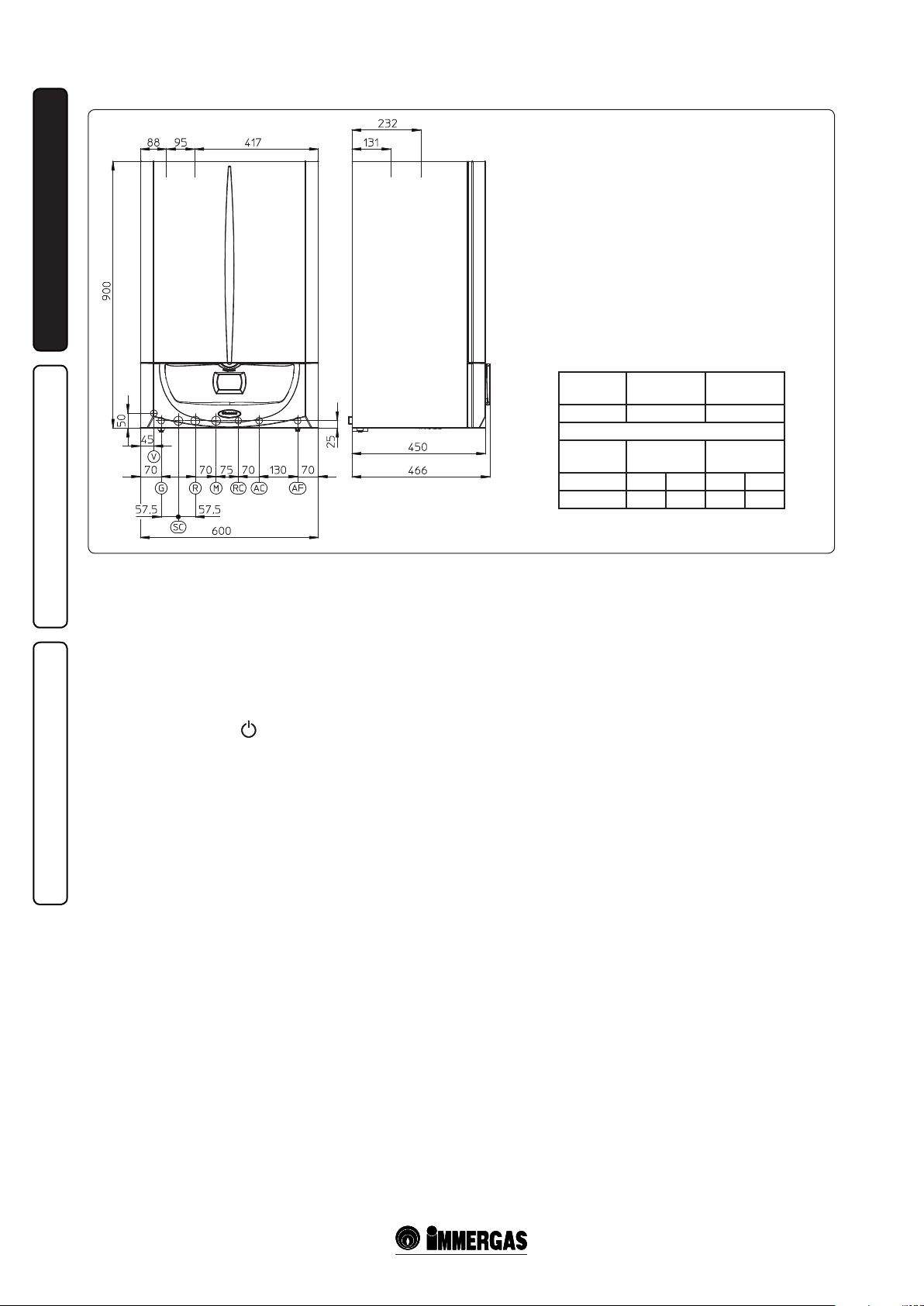
1.2 MAIN DIMENSIONS.
INSTALLATORUSER
1-2
Key:
V - Electric attachment
G - Gas supply
SC - Condensate drain
(minimum internal diameter Ø 13 mm)
R - System return
M - System ow
RC - Domestic hot water pump (optional)
AC - Domestic hot water outlet
AF - Domestic hot water inlet
1.3 ANTIFREEZE PROTECTION.
Minimum temperature -5°C. e boiler comes
standard with an anti-freeze function that
activates the pump and burner when the system
water temperature in the boiler falls below 4°C.
e anti-freeze function is only guaranteed if:
- the boiler is correctly connected to gas and
electricity power supply circuits;
- the boiler is powered constantly;
- the boiler is not in stand-by ( );
- the boiler is not in no ignition block (par. 2.6);
- the boiler essential components are not faulty.
In these conditions the boiler is protected against
freezing to an environmental temperature of -5°C.
Minimum temperature -15°C. If the boiler is
installed in a place where the temperature falls
below -5°C and in the event there is no gas (or
the boiler goes into ignition block), the appliance
can freeze.
MAINTENANCE TECHNICIAN
To prevent the risk of freezing follow the
instructions below:
- protect the central heating circuit from freezing
by introducing a top quality anti-freeze liquid
into this circuit, which is not noxious to health.
e instructions of the manufacturer of this
liquid must be followed scrupulously regarding
the percentage necessary with respect to the
minimum temperature at which the system
must be kept. An aqueous solution must be
made with potential pollution class of water 2.
e materials used for the central heating circuit
of Immergas boilers resist ethylene and propylene
glycol based antifreeze liquids (if the mixtures are
prepared perfectly).
For life and possible disposal, follow the
supplier's instructions.
- Protect the condensate drain trap and circuit
board against freezing by using an accessory
that is supplied on request (anti-freeze kit)
comprising two electric heating elements,
the relevant cables and a control thermostat
(carefully read the installation instructions
contained in the accessory kit pack).
Boiler anti-freeze protection is thus ensured only if:
- the boiler is correctly connected to gas and
electricity power supply circuits and powered;
- the anti-freezing kit components are ecient.
In these conditions the boiler is protected against
freezing to temperature of -15°C.
The warranty does not cover damage due to
interruption of the electrical power supply and
failure to comply with that stated on the previous
page.
N.B.: if the boiler is installed in places where the
temperature falls below 0°C the domestic water
and heating attachment pipes must be insulated.
Height
(mm)
900 600 466
GAS
G AC AF R M
1/2” 1/2” 1/2” 3/4” 3/4”
Width
(mm)
ATTACHMENTS
DOMESTIC
HOT WATER
Depth
(mm)
SYSTEM
6
1.4 CONNECTION UNIT SUPPLIED AS
STANDARD WITH THE BOILER.
Gas connection (Appliance category II
Our boilers are designed to operate with methane
2H3P
).
gas (G20) and LPG. Supply pipes must be the
same as or larger than the 1/2”G boiler tting.
Before connecting the gas line, carefully clean
inside all the fuel feed system pipes to remove any
residue that could impair boiler eciency. Also
make sure the gas corresponds to that for which
the boiler is prepared (see boiler data-plate).
If dierent, the appliance must be converted
for operation with the other type of gas (see
converting appliance for other gas types). e
dynamic gas supply (methane or LPG) pressure
must also be checked according to the type used
in the boiler, which must be in compliance, as
insucient levels can reduce generator output
and cause malfunctions.
Ensure correct gas cock connection. e gas
supply pipe must be suitably dimensioned
according to current regulations in order to
guarantee correct gas ow to the burner even
in conditions of maximum generator output
and to guarantee appliance eciency (technical
specifications). The coupling system must
conform to standards.
Fuel gas quality. The appliance has been
designed to operate with gas free of impurities;
otherwise it is advisable to fit special filters
upstream from the appliance to restore the
purity of the gas.
Storage tanks (in case of supply from LPG
depot).
- New LPG storage tanks may contain residual
inert gases (nitrogen) that degrade the mixture
delivered to the appliance casing functioning
anomalies.
- Due to the composition of the LPG mixture,
layering of the mixture components may occur
during the period of storage in the tanks. is
can cause a variation in the heating power of
the mixture delivered to the appliance, with
subsequent change in its performance.
Hydraulic connection.
Attention: In order not to void the warranty
before making the boiler connections, carefully
clean the heating system (pipes, radiators, etc.)
with special pickling or de-scaling products to
remove any deposits that could compromise
correct boiler operation.
A chemical treatment for the thermal system
water is prescribed according to the current
technical regulations, until the system and the
lime scale apparatus is preserved (for example,
limescale deposits), from the slurry formation
and other noxious deposits.
Water connections must be made in a rational way
using the couplings on the boiler template. e
boiler safety valve outlet must be connected to
a draining funnel. Otherwise, the manufacturer
declines any responsibility in case of ooding if
the drain valve cuts in.
Important: to preserve the duration of appliance
eciency features, in the presence of water whose
features can lead to the deposit of lime scale,
installation of the “polyphosphate dispenser” kit
is recommended.
Condensate drain. To drain the condensate
produced by the appliance, it is necessary
to connect to the drainage system by means
of acid condensate resistant pipes having an
internal diameter of at least 13 mm. e system
connecting the appliance to the drainage system
must be carried out in such a way as to prevent
freezing of the liquid contained in it. Before
appliance start-up, ensure that the condensate
can be correctly removed. Also, comply with
national and local regulations on discharging
waste waters.
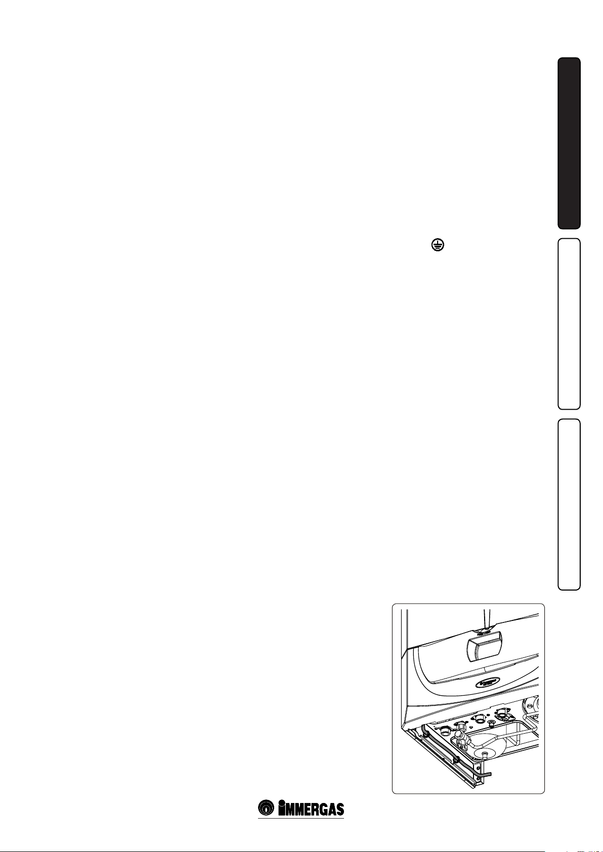
Electrical connection: The “Victrix Zeus
Superior kW” boiler has an IPX5D protection
rating for the entire appliance. Electrical safety of
the appliance is reached only when it is correctly
connected to an efficient earthing system as
specied by current safety standards.
Attention: Immergas S.p.A. declines any
responsibility for damage or physical injury
caused by failure to connect the boiler to an
ecient earth system or failure to comply with
the reference standards.
Also ensure that the electrical installation
corresponds to maximum absorbed power
specications as shown on the boiler data-plate.
Boilers are supplied complete with an “X” type
power cable without plug. e power supply
cable must be connected to a 230V ±10% / 50Hz
mains supply respecting L-N polarity and earth
connection . is network must also have
an omnipolar circuit breaker with class III overvoltage category.
To protect against possible voltage dispersions,
it is necessary to envision a dierential safety
device type A.
When replacing the power supply cable, contact
a qualied technician (e.g. the Immergas AerSales Technical Assistance Service). e power
cable must be laid as shown (Fig. 1-3).
In the event of mains fuse replacement on the
P.C.B., use a 3.15A quick-blow fuse. For the
main power supply to the appliance, never use
adapters, multiple sockets or extension leads.
INSTALLATORUSER
MAINTENANCE TECHNICIAN
POWER SUPPLY
CAVO
CABLE
1-3
7
ALIMENTAZIONE
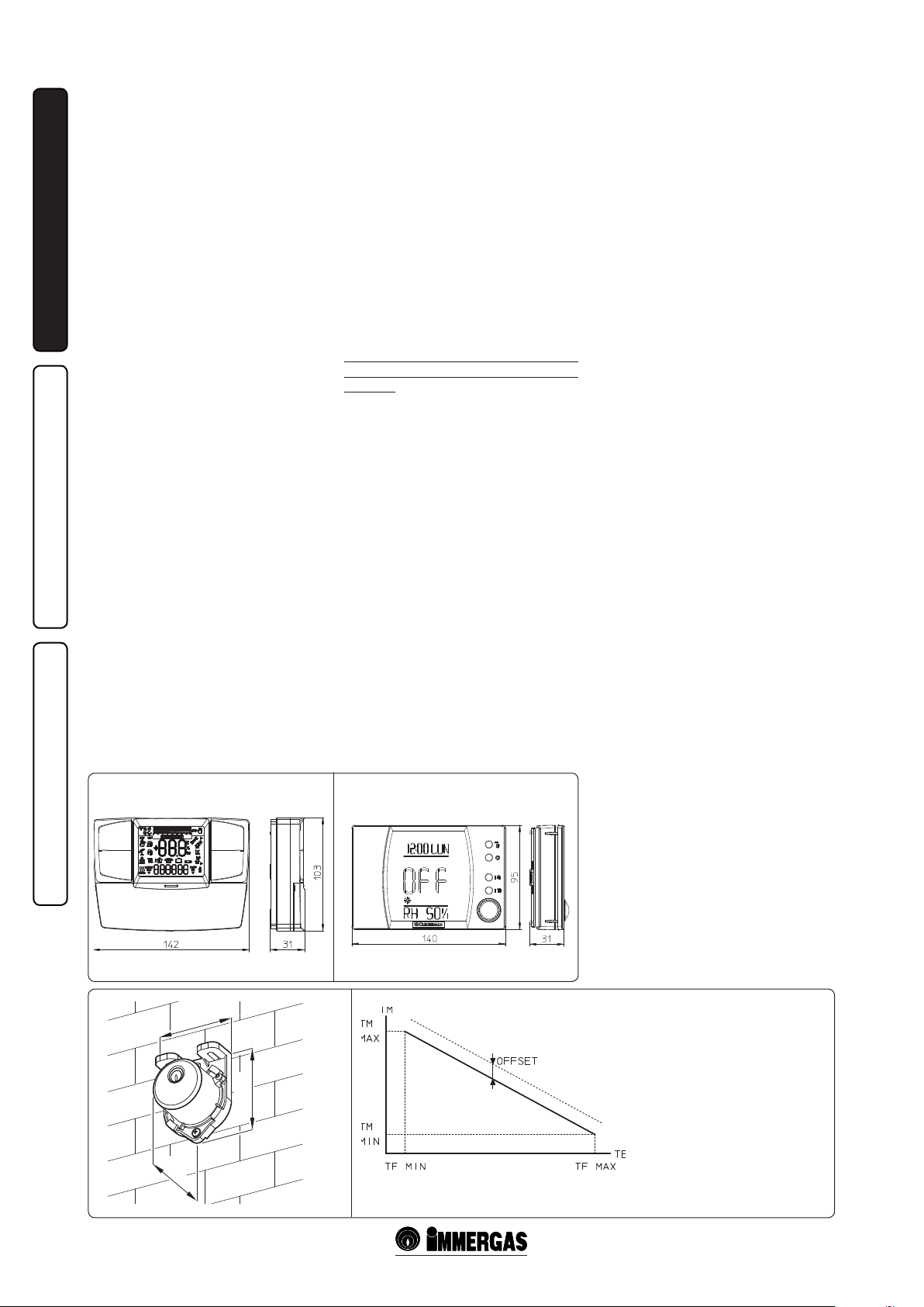
1.5 REMOTE CONTROLS AND
ROOM CHRONOTHERMOSTATS
OPTIONAL.
e boiler is prepared for the application of room
chrono-thermostats or remote controls, which
are available as optional kits.
All Immergas chrono-thermostats are connected
with 2 wires only. Carefully read the user and
assembly instructions contained in the accessory
kit.
• On/O digital chrono-thermostat (Fig. 1-4).
e chrono-thermostat allows:
- to set two room temperature values: one for
INSTALLATORUSER
day (comfort temperature) and one for night
(lower temperature);
- set a weekly program with four daily switch-
on/o;
- selecting the required function mode from
the various possible alternatives:
- manual operation (with adjustable
temperature).
- automatic operation (with set program).
- forced automatic operation (temporarily
modifying the temperature of the automatic
program).
e chrono-thermostat is powered by two 1.5V
LR 6 type alkaline batteries.
• ere are two types of remote controls available:
Comando Amico Remoto remote control
V2
(CARV2) (Fig. 1-4) and Super Comando
Amico Remoto remote control (Super CAR)
(Fig. 1-5) both with room chrono-thermostat
functioning. In addition to the functions
described in the previous point, the chronothermostat panels enable the user to control all
the important information regarding operation
of the appliance and the central heating system
with the opportunity of easily intervening on
the previously set parameters without having to
go to the place where the appliance is installed.
e panel is provided with self-diagnosis to
display any boiler functioning anomalies.
e climate chrono-thermostat incorporated
into the remote panel enables the system ow
temperature to be adjusted to the actual needs
of the room being heated, in order to obtain
the desired room temperature with extreme
precision and therefore with evident saving in
running costs. e chrono-thermostat is fed
directly by the boiler by means of the same 2
wires used for the transmission of data between
boiler and chrono-thermostat.
Important: if the system is subdivided into
zones using the relevant kit, the CAR V2 and
the Super CAR must be used with its climate
thermostat function disabled, i.e. it must be set
to On/O mode.
CARV2, Super CAR or On/Off chronothermostat electrical connection (Optional).
e operations described below must be performed
after having removed the voltage from the
appliance. e eventual On/O environment
chrono-thermostat must be connected to clamps
40 and 41 eliminating jumper X40 (Fig. 3-2).
Make sure that the On/O thermostat contact is
of the “clean” type, i.e. independent of the mains
supply, otherwise the P.C.B. would be damaged.
Any CARV2 or Super CAR must be connected
by means of terminals IN+ and IN- to terminals
42 and 43 on the circuit board, eliminating
jumper X40 and respecting polarity (Fig. 3-2).
Connection with the wrong polarity prevents
functioning, but without damaging the Remote
control. e boiler can only be connected to one
remote control.
Important: if the Comando Remoto remote
control is used, arrange two separate lines in
compliance with current regulations regarding
electrical systems. No boiler pipes must ever be
used to earth the electric system or telephone
lines. Ensure elimination of this risk before
making the boiler electrical connections.
Installation with system operating at direct
low temperature. e boiler can directly feed a
low temperature system by acting on parameter
“P66” (Par. 3.8) and setting the ow temperature
adjustment range “P66/A” and “P66/B”. In this
situation it is good practice to insert a safety
device in series with the power supply and boiler.
is device is made up from a thermostat with
a temperature limit of 60°C. The thermostat
must be positioned on the system delivery pipe
at a distance of at least 2 metres from the boiler.
1.6 EXTERNAL TEMPERATURE PROBE
OPTIONAL.
e boiler is prepared for the application of the
external probe (Fig. 1-6), which is available as
an optional kit. Refer to the relative instruction
sheet for positioning of the external probe. e
probe can be connected directly to the boiler
electrical system and allows the max. system
ow temperature to be automatically decreased
when the external temperature increases, in
order to adjust the heat supplied to the system
according to the change in external temperature.
The external probe always operates when
connected, regardless of the presence or type of
room chrono-thermostat used and can work in
combination with Immergas timer thermostats.
e correlation between system ow temperature
and external temperature is determined by the
parameters set in menu “M5” under “P66”
according to the curves represented in the
diagram (Fig. 1-7). e electric connection of
the external probe must be made on clamps 38
and 39 on the boiler P.C.B. (Fig. 3-2).
Comando Amico Remoto remote controlV2 (CARV2)
On/O digital chrono-thermostat.
MAINTENANCE TECHNICIAN
45
31
58
Super Comando Amico Remoto
remote control (Super CAR)
1-4 1-5
EXTERNAL PROBE
Correction law of the ow temperature
depending on the external temperature
and user adjustments of the central heating
TM-MAX/MIN = Selected ow temp. range.
TE = External temperature.
1-6 1-7
temperature.
8
1.7 IMMERGAS FLUE SYSTEMS.
Immergas supplies various solutions separately
from the boilers regarding the installation of air
intake terminals and ue extraction, which are
fundamental for boiler operation.
Attention: the boiler must be installed
exclusively with an original Immergas “Green
Range” air intake and fume extraction system
in plastic, as envisioned by Standard in force.
e plastic pipes cannot be installed outdoors,
for tracts longer than 40 cm, without suitable
protection from UV rays and other atmospheric
agents.
This system can be identified by an
identification mark and special distinctive
marking bearing the note: “only for condensing
b oi l er s ”.
• Resistance factors and equivalent lengths.
Each ue component has a Resistance Factor
based on experimental tests and specified
in the table below. e Resistance Factor for
individual components is independent from
the type of boiler on which it is installed
and has a dimensionless size. It is however,
conditioned by the temperature of the uids
that pass through the pipe and therefore,
varies according to applications for air intake
or ue exhaust. Each single component has a
resistance corresponding to a certain length
in metres of pipe of the same diameter; the
so-called equivalent length, obtained from the
ratio between the relative Resistance Factors.
All boilers have an experimentally obtainable
maximum Resistance Factor equal to 100.
The maximum Resistance Factor allowed
corresponds to the resistance encountered with
the maximum allowed pipe length for each
type of Terminal Kit. is information allows
calculations to be made to verify the possibility
of setting up various ue congurations.
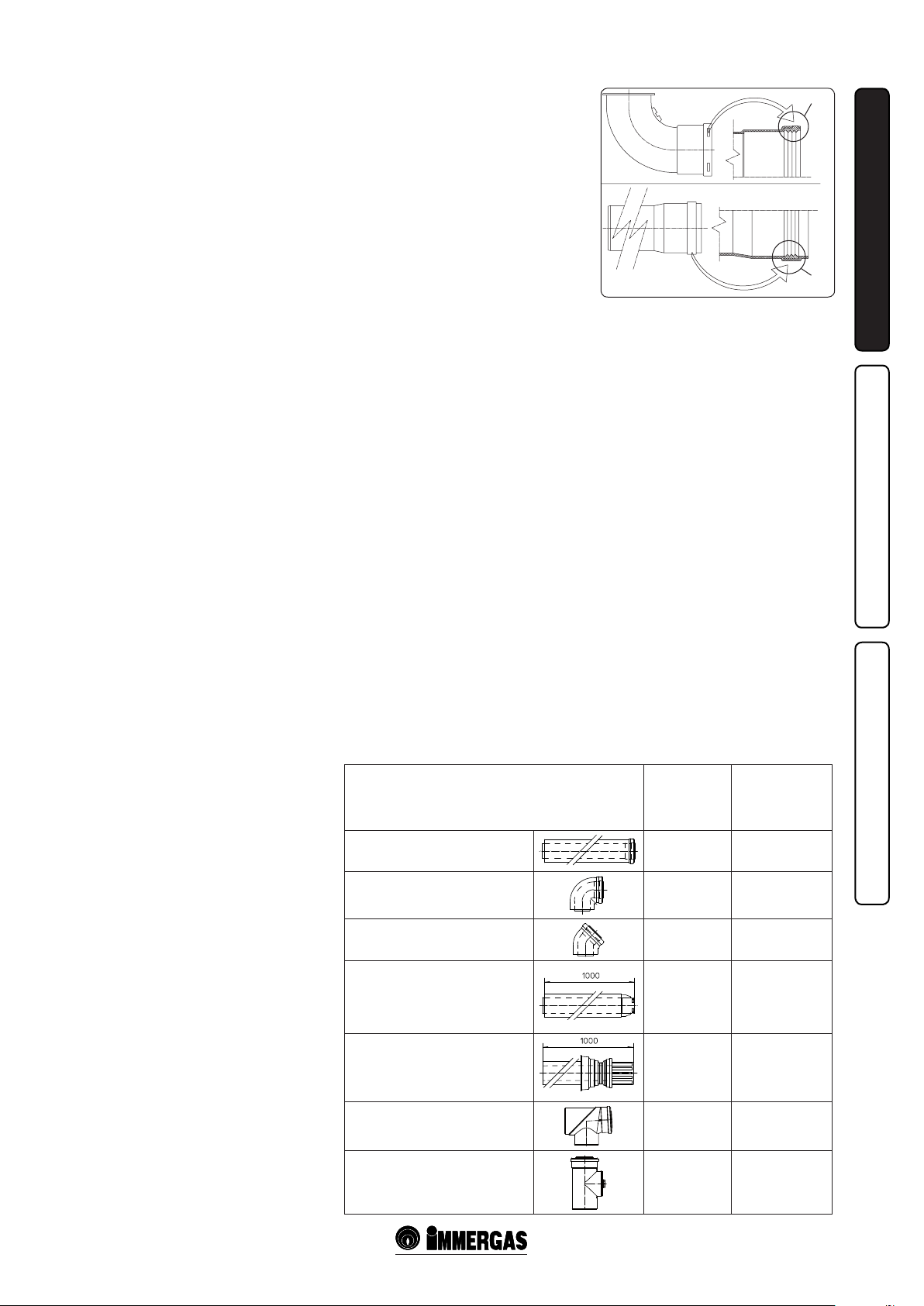
• Positioning of the gaskets (black) for “green
range” ue extraction systems. Position the
gasket correctly (for bends and extensions)
(Fig. 1-8):
- gasket (A) with notches, to use for bends;
- gasket (B) without notches, to use for
extensions.
N.B.: if component lubrication (already carried
out by the manufacturer) is not sufficient,
remove the residual lubricant using a dry cloth,
then to ease tting spread the elements with
common or industrial talc.
• Coupling extension pipes and concentric
elbows. To install push-tting extensions with
other elements of the ue, proceed as follows:
Install the concentric pipe or elbow with the
male side (smooth) on the female section
(with lip seal) to the end stop on the previously
installed element in order to ensure sealing
eciency of the coupling.
Attention: if the exhaust terminal and/or
extension concentric pipe needs shortening,
consider that the internal duct must always
protrude by 5 mm with respect to the external
duct.
• N.B.: for safety purposes, do not obstruct
the boiler intake-exhaust terminal, even
temporarily.
• N.B.: when installing horizontal pipes,
a minimum inclination of 3% must be
maintained and a section clamp with pin must
be installed every 3 metres.
1.8 TABLES OF RESISTANCE FACTORS
AND EQUIVALENT LENGTHS.
TYPE OF DUCT
Concentric pipe Ø80/125 m 1
Concentric bend 90° Ø80/125
1-8
Resistance
Factor
(R)
2.1
3.0
(A)
(B)
Equivalent
length in m of
concentric pipe
Ø80/125
1
1.4
INSTALLATORUSER
MAINTENANCE TECHNICIAN
Concentric bend 45° Ø80/125
Terminal complete with concentric
horizontal intake-exhaust Ø80/125
Terminal complete with concentric
vertical intake-exhaust Ø80/125
Concentric bend 90° Ø80/125 with
inspection
Stub pipe with inspection Ø80/125
9
2.1
2.8
3.6
3.4
3.4
1
1.3
1.7
1.6
1.6
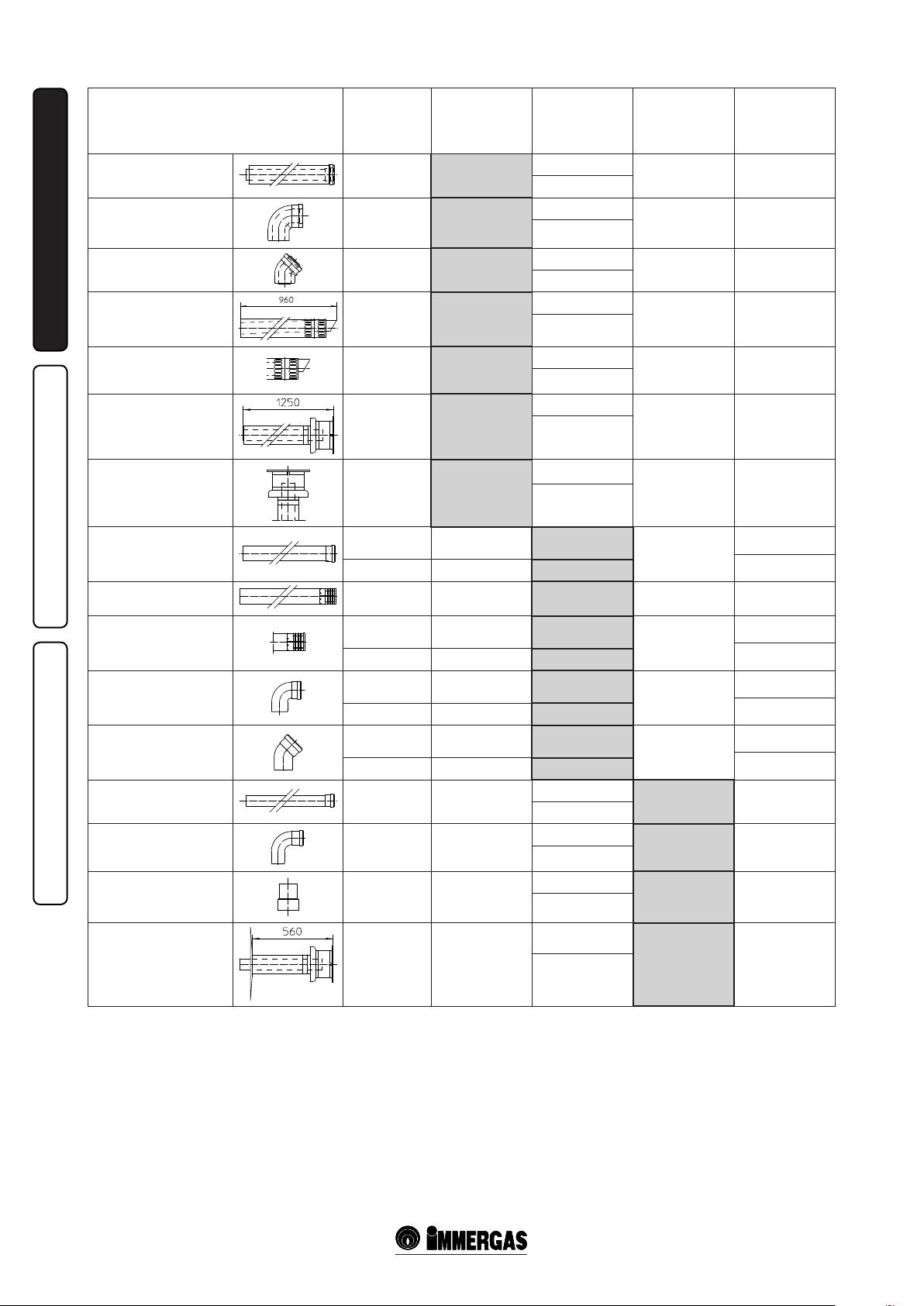
Concentric pipe Ø60/100
m 1
Concentric bend 90°
Ø60/100
Concentric bend 45°
Ø60/100
INSTALLATORUSER
Terminal complete with
concentric horizontal
intake-exhaust Ø60/100
Concentric horizontal
intake- exhaust terminal
Ø60/100
Terminal complete with
concentric vertical intakeexhaust Ø60/100
TYPE OF DUCT
Resistance
Factor
(R)
Intake and
Exhaust 6.4
Intake and
Exhaust 8.2
Intake and
Exhaust 6.4
Intake and
Exhaust 15
Intake and
Exhaust 10
Intake and
Exhaust 16.3
Equivalent
length in m of
concentric pipe
Ø60/100
m 1
m 1.3
m 1
m 2.3
m 1.5
m 2.5
Equivalent
length in metres
of pipe Ø80
Intake m 7.3
Exhaust m 5.3
Intake m 9.4
Exhaust m 6.8
Intake m 7.3
Exhaust m 5.3
Intake m 17.2
Exhaust m 12.5
Intake m 11.5
Exhaust m 8.3
Intake m 18.7
Exhaust m 13.6
Equivalent
length in metres
of pipe Ø60
Exhaust m 1.9 m 3.0
Exhaust m 2.5 m 3.9
Exhaust m 1.9 m 3.0
Exhaust m 4.5 m 7.1
Exhaust m 3.0 m 4.7
Exhaust m 4.9 m 7.7
Equivalent
length in m of
concentric pipe
Ø80/125
Concentric vertical intakeexhaust terminal Ø60/100
Pipe Ø80, 1 m
Complete intake terminal
Ø80, 1 m
Intake terminal Ø 80
Exhaust terminal Ø 80
Bend 90° Ø80
Bend 45° Ø80
Pipe Ø60 m 1 for ducting Exhaust 3.3 m 0.5
Bend 90° Ø60 for ducting
MAINTENANCE TECHNICIAN
Reduction Ø80/60
Intake and
Exhaust 9
Intake 0.87 m 0.1 Intake m 1.0
Exhaust 1.2 m 0.2 Exhaust m 1.0
Intake 3 m 0.5 Intake m 3.4 Exhaust m 0.9 m 1.4
Intake 2.2 m 0.35 Intake m 2.5
Exhaust 1.9 m 0.3 Exhaust m 1.6
Intake 1.9 m 0.3 Intake m 2.2
Exhaust 2.6 m 0.4 Exhaust m 2.1
Intake 1.2 m 0.2 Intake m 1.4
Exhaust 1.6 m 0.25 Exhaust m 1.3
Exhaust 3.5 m 0.55
Intake and
Exhaust 2.6
m 1.4
m 0.4
Intake m 10.3
Exhaust m 7.5
Intake 3.8
Exhaust 2.7
Intake 4.0
Exhaust 2.9
Intake m 3.0
Exhaust m 2.1
Exhaust m 2.7 m 4.3
m 0.4
Exhaust m 0.4
m 0.5
m 1
Exhaust m 0.6
m 0.9
m 0.9
Exhaust m 0.8
m 1.2
m 0.5
Exhaust m 0.5
0.7
Exhaust m 1.0 m 1.5
Exhaust m 1.1 m 1.6
Exhaust m 0.8 m 1.2
Terminal complete with
exhaust vertical Ø60 for
ducting
Exhaust 12.2 m 1.9
10
Intake m 14
Exhaust m 3.7 m 5.8
Exhaust m 10.1
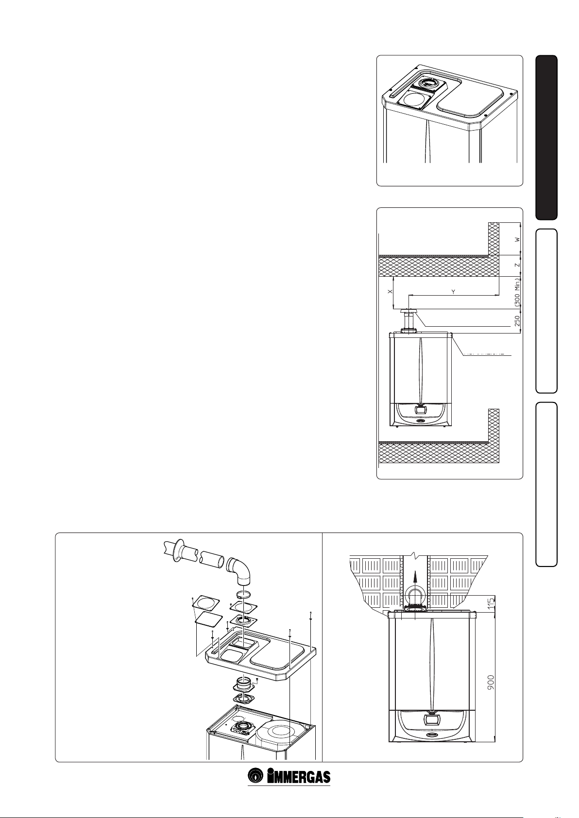
1.9 OUTDOOR INSTALLATION IN PARTIALLY PROTECTED AREA.
N.B.: a partially protected area is one in which the
appliance is not exposed to the direct action of the
weather (rain, snow, hail, etc...).
• Conguration type B, open chamber and
forced draught.
Using the relevant cover kit direct air intake is
possible (Fig. 1-9) and combustion products are
exhausted into a single ue or directly to the
outside. In this conguration it is possible to
install the boiler in a partially protected place.
In this conguration the boiler is classied as
type B23.
With this conguration:
- air intake takes place directly from the
environment in which the appliance is installed
(external);
- the ue exhaust must be connected to its own
individual ue or channelled directly into the
external atmosphere.
The technical regulations in force must be
respected.
• Kit assembly (Fig. 1-11): Remove the two
plugs and the gaskets present from the two
lateral holes with respect to the central one.
Now cover the right intake hole using the
relevant plate, xing it onto the le side using
the two previously-removed screws. Install the
Ø80 outlet ange on the central hole of the
boiler, taking care to insert the gasket supplied
with the kit and tighten by means of the screws
provided. Install the upper cover, xing it using
the 4 screws present in the kit, positioning the
relevant gaskets. Engage the 90° Ø80 bend
with the male side (smooth) in the female side
(with lip seal) of the Ø80 ange until it stops.
Introduce the gasket, making it run along the
bend. Fix it using the sheet steel plate and
tighten by means of the straps present in the
kit, making sure to block the 4 gasket aps. Fit
the male side (smooth) of the exhaust terminal
into the the female side of the bend 90° Ø80,
making sure that the relevant wall sealing plate
is already tted; this will ensure the hold and
joining of the elements making up the kit.
Max. length of exhaust duct. The flue pipe
(vertical or horizontal) can be extended to a max.
length of 30 straight metres.
• Coupling of extension pipes. To install push-
tting extensions with other elements of the
ue, proceed as follows: Couple the pipe or
elbow with the male side (smooth) in the
female side (with lip seal) to the end stop on the
previously installed element. is will ensure
sealing eciency of the coupling.
Example of installation with direct vertical
terminal in partially protected location. When
the vertical terminal for direct discharge of
combustion products is used, a minimum gap
of 300 mm must be le between the terminal
and the balcony above. e height X+Y+Z+W
evaluated with respect to the balcony above,
must be equal to or more than 2000 mm. (Fig.
1-10). e term W must only be considered if the
balcony above has closed balustrade (W=0 if the
balustrade is open).
• Conguration without cover kit in a partially
protected location (type C boiler)
By leaving the side plugs tted it is possible
to install the appliance externally without
the cover kit. Installation takes place using
the Ø60/100 and Ø80/125 concentric intake/
exhaust and separator Ø80/80 kits. Refer to
the paragraph relative to indoor installation.
In this configuration the upper cover kit
guarantees additional protection for the boiler.
It is recommended but not compulsory.
1-9
1-10
VERTICAL TERMINAL KIT
FOR DIRECT DISCHARGE
INTAKE
COVER KIT
INSTALLATORUSER
e cover kit includes:
N° 1 Heat moulded cover
N°1 Gasket clamping plate
N°1 Gasket
N°1 Gasket clamp
N°1 N° 1 Intake hole covering plate
e terminal kit includes:
N°1 Gasket
N°1 Exhaust ange Ø 80
N°1 Bend 90° Ø 80
N°1 Exhaust pipe Ø 80
N°1 Wall sealing plate
11
1-11
1-12
MAINTENANCE TECHNICIAN

1.10 HORIZONTAL CONCENTRIC KIT INSTALLATION.
Type C configuration, sealed chamber and
fan assisted.
Horizontal intake - exhaust kit Ø60/100. Kit
assembly (Fig. 1-13): install the bend with ange
(2) on the central hole of the boiler, positioning
the gasket (1) (which does not require lubrication)
positioning it with the circular projections
downwards in contact with the boiler ange
and tighten using the screws preset in the kit.
Fit the Ø60/100 (3) concentric terminal pipe
with the male end (smooth) to the female end
INSTALLATORUSER
of the bend (2) up to the stop; making sure that
the internal and external wall sealing plate have
been tted, this will ensure sealing and joining
of the elements making up the kit.
• Extensions for horizontal kit Ø60/100
(Fig. 1-14). e kit with this conguration
can be extended up to a max. horizontal
distance of 12.9 m including the terminal with
grid and excluding the concentric bend leaving
the boiler. is conguration corresponds to
a resistance factor of 100. In these cases the
special extensions must be requested.
Horizontal intake - exhaust kit Ø80/125. Kit
assembly (Fig. 1-15): for the installation of kit
Ø80/125 the anged adapter kit must be used to
be able to install the ue system Ø80/125. Install
the anged adapter (2) on the central hole of the
boiler, positioning the gasket (1) (which does not
require lubrication) with the circular projections
downwards in contact with the boiler ange and
tighten using the screws present in the kit. Engage
the bend (3) with the male side (smooth) until it
is fully home on the adapter (1). Fit the Ø80/125
(5) concentric terminal pipe with the male end
(smooth) to the female end of the bend (4)
(with lip seal) up to the stop; making sure that
the internal (6) and external wall sealing plates
(7) have been tted, this will ensure sealing and
joining of the elements making up the kit.
• Extensions for horizontal kit Ø80/125
(Fig. 1-16). e kit with this conguration
can be extended up to a max. distance of 32 m
including the terminal with grid and excluding
the concentric bend leaving the boiler. If
additional components are assembled, the
length equivalent to the maximum allowed
must be subtracted. In this case the special
extensions must be requested.
• External grid. N.B.: for correct functioning
of the system the terminal with grid must be
installed correctly ensuring that, the "high"
indication present on the terminal is respected
on installation.
2
1
3
4
e kit includes:
N° 1 - Gasket (1)
N° 1 - Concentric bend Ø60/100 (2)
N° 1 - Concentric intake-exhaust terminal Ø60/100 (3)
N° 1 - Internal wall sealing plate (4)
N° 1 - External wall sealing plate (5)
MAINTENANCE TECHNICIAN
3
2
4
5
1
e adapter Kit includes:
N° 1 - Gasket (1)
N° 1 - Adapter
Ø80/125 (2)
1-15
e Kit Ø80/125 includes:
N° 1 - Concentric bend Ø80/125 at
87° (3)
N° 1 - Concentric intake-exhaust
terminal Ø80/125 (4)
N° 1 - Internal wall sealing plate (5)
N° 1 - External wall sealing plate (6)
e remaining components of the kit are
not to be used
C13
C13
5
1-13 1-14
C13
C13
6
1-16
12
 Loading...