

Immergas VICTRIX ZEUS 26 2 ERP Instruction And Recommendation Booklet
Instruction and
*1.037936ENG*
recommendation booklet
IE
VICTRIX ZEUS
26 2 ErP

Dear Customer,
Our compliments for having chosen a top-quality Immergas product, able to assure well-being and safety for a long period of time. As an Immergas customer
you can also count on a qualied aer-sales service, prepared and updated to guarantee constant eciency of your boiler. Read the following pages carefully: you
will be able to draw useful suggestions regarding the correct use of the appliance, the respect of which, will conrm your satisfaction for the Immergas product.
Contact our area authorised aer-sales centre as soon as possible to request commissioning.
Our technician will verify the correct functioning conditions; he will perform the necessary calibrations and will demonstrate the correct use of the generator.
For assistance and scheduled maintenance contact Authorised Aer-Sales centres: they have original spare parts and are specically trained directly by the
manufacturer.
General recommendations
All Immergas products are protected with suitable transport packaging.
e material must be stored in dry environments protected against bad weather.
e instruction book is an integral and essential part of the product and must be consigned to the new user also in the case of transfer or succession of ownership.
It must be stored with care and consulted carefully, as all of the warnings provide important safety indications for installation, use and maintenance stages.
is instructions manual provides technical information for installing Immergas boilers. As for the other issues related to boiler installation (e.g. safety in the work
site, environment protection, injury prevention), it is necessary to comply with the provisions specied in the regulations in force and principles of good practice.
In compliance with legislation in force, the systems must be designed by qualied professionals, within the dimensional limits established by the Law. Installation
and maintenance must be performed in compliance with the regulations in force, according to the manufacturer's instructions and by professionally qualied
sta, intending sta with specic technical skills in the plant sector, as envisioned by the Law.
Improper installation or assembly of the Immergas appliance and/or components, accessories, kit and devices can cause unexpected problems to people, animals
and objects. Read the instructions provided with the product carefully to ensure a proper installation.
Maintenance must be carried out by skilled technical sta. e Authorised Aer-sales Service represents a guarantee of qualications and professionalism.
e appliance must only be destined for the use for which it has been expressly declared. Any other use will be considered improper and therefore potentially
dangerous.
If errors occur during installation, operation and maintenance, due to non compliance with technical laws in force, standards or instructions contained in this
book (or however supplied by the manufacturer), the manufacturer is excluded from any contractual and extra-contractual liability for any damages and the
appliance warranty is invalidated.
For further information regarding legislative and statutory provisions relative to the installation of gas heat generators, consult the Immergas site at the
following address: www.immergas.com
CE DECLARATION OF CONFORMITY
(according to ISO/IEC 17050-1)
e company IMMERGAS S.p.A., with registered oce in via Cisa Ligure 95 42041 Brescello (RE) whose design, manufacturing, and aer sale assistance
processes comply with the requirements of standard UNI EN ISO 9001:2008,
e boiler model Victrix Zeus 26 2 ErP complies with European Directives and Delegated European Regulations listed below:
“Eco-design” Directive 2009/125/EC, “Energy labelling” Directive 2010/30/EC, EU Regulation 811/2013, EU Regulation 813/2013, “Gas Appliance” Directive 2009/142/EC, “Electromagnetic Compatibility” Directive 2004/108/EC, “Performance” Directive 92/42/EC and “Low Voltage” Directive 2006/95/EC.
Immergas S.p.A. declines all liability due to printing or transcription errors, reserving the right to make any modications to its technical and commercial
documents without prior notice.
DECLARES that:
Mauro Guareschi
Research & Development Director
Signature:

INDEX
INSTALLER page MAINTENANCE TECHNICIAN page
USER page
1 Boiler installation .......................................5
1.1 Installation recommendations. ................. 5
1.2 Main dimensions. ......................................6
1.3 Anti-freeze protection. ...............................6
1.4 Gas connection. ..........................................7
1.5 Hydraulic connection. ................................7
1.6 Electrical connection. ................................7
1.7 Remote controls and room
chrono-thermostats (Optional). ...............8
1.8 External temperature probe
(Optional). ................................................... 8
1.9 Immergas ue systems. .............................9
1.10 Tables of resistance factors
and equivalent lengths. ..............................9
1.11 Outdoor installation
in a partially protected area.
1.12 Concentric horizontal kit installation. ...12
1.13 Concentric vertical kit installation. ........13
1.14 Separator kit installation. ......................... 14
1.15 Adaptor C9 kit installation. ....................15
1.16 Ducting of ues or technical slots. .........16
1.17 Conguration type B, open
chamber and fan assisted for indoors.
1.18 Flue gas exhaust to ue/chimney. ........... 16
1.19 Flues, chimneys, chimney
pots and terminals.
1.20 System lling. ............................................ 17
1.21 Condensate trap lling. ............................17
1.22 Gas system start-up. ................................. 17
1.23 Boiler start up (ignition). .........................17
1.24 Domestic hot water storage tank unit. ...17
1.25 Kits available on request. .........................17
1.26 Circulation pump......................................18
1.27 Boiler components. ...................................20
.................... 11
... 16
................................... 17
2 Use and maintenance instructions .........21
2.1 Cleaning and maintenance. .....................21
2.2 General warnings. ..................................... 21
2.3 Control panel.............................................21
2.4 Ignition of the boiler. ................................22
2.5 Troubleshooting. .......................................22
2.6 Boiler shutdown ........................................23
2.7 Restoring central heating
system pressure.
2.8 System draining. ......................................23
2.9 Storage tank draining. ..............................23
2.10 Anti-freeze protection. .............................23
2.11 Case cleaning. ............................................ 23
2.12 Decommissioning. ....................................23
............................................ 23
3 Boiler start-up (initial check) ..................24
3.1 Plumbing diagram. ...................................24
3.2 Wiring diagram. ........................................25
3.3 Troubleshooting. .......................................25
3.4 Converting the boiler
to other types of gas. .................................26
3.5 Calibration phase. .....................................26
3.6 Nominal heat output calibration. ...........26
3.7 Adjustment of the air-gas ratio. ..............27
3.8 Checks following conversion
to another type of gas.
3.9 Pump operating mode. ............................27
3.10 Domestic hot water mode
selector switch
3.11 Solar panels
coupling function. ....................................27
3.12 ''Chimney sweep'' function. .....................27
3.13 Pump anti-lock function. ........................27
3.14 ree-way anti-block function. ..............27
3.15 Permanent reduction of
timing function. ........................................ 27
3.16 Radiators antifreeze function. ................. 27
3.17 Flow temperature value
in central heating mode. ..........................27
3.18 Yearly appliance check
and maintenance. ......................................28
3.19 Casing removal. ........................................29
3.20 Variable heat output. ................................30
3.21 Combustion parameters. ........................30
3.22 Technical data. ..........................................31
3.23 Key for data plate. .....................................32
3.24 Technical parameters for mixed boilers
(in compliance with Regulation
813/2013). .................................................. 33
3.25 Product data sheet (in compliance
with Regulation 811/2013). .....................33
3.26 Parameters for lling in
the assembly sheet. ...................................34
.............................. 27
............................................. 27
4
SI
NO
BOILER INSTALLATION
1
1.1 INSTALLATION
RECOMMENDATIONS.
e Victrix Zeus 26 2 ErP boiler has been designed for wall mounted installation only; for
heating and production of domestic hot water
for domestic use and similar purposes.
e place of installation of the appliance and
relative Immergas accessories must have suitable
features (technical and structural) such to allow
(always in safety, efficiency and comfortable
conditions):
- installation (according to the provisions of the
technical legislation and technical regulations);
- maintenance operations (including scheduled,
periodic, routine and special maintenance);
- removal (to outdoors in the place for loading
and transporting the appliances and components) as well as their eventual replacement
with appliances and/or equivalent components.
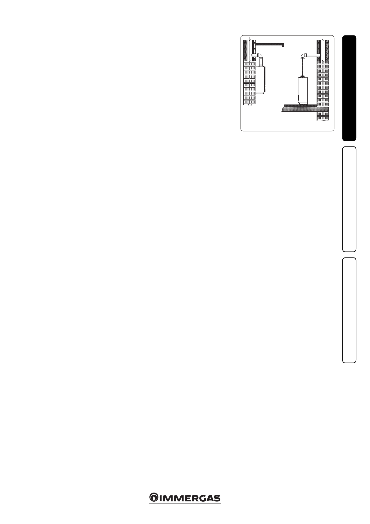
e wall surface must be smooth, without any
protrusions or recesses enabling access to the
rear part. ey are not designed to be installed
on plinths or oors (Fig. 1-1).
By varying the type of installation the classication of the boiler also varies, precisely:
- Type B23 or B53 boiler if installed using the
relevant terminal for air intake directly from
the room in which the boiler has been installed.
- Type C boiler if installed using concentric
pipes or other types of pipes envisioned for
sealed chamber boilers for air intake and expulsion of ue gas.
Note: appliance classication is provided in the
depictions of the various installation solutions
shown on the following pages.
Only professionally enabled companies are
authorised to install Immergas gas appliances.
Installation must be carried out according to
regulation standards, current legislation and in
compliance with local technical regulations and
the required technical procedures.
Before installing the appliance, ensure that it is
delivered in perfect condition; if in doubt, contact
the supplier immediately. Packing materials (staples, nails, plastic bags, polystyrene foam, etc.)
constitute a hazard and must be kept out of the
reach of children. If the appliance is installed inside or between cabinets, ensure sucient space
for normal servicing; therefore it is advisable to
leave clearance of at least 3 cm between the boiler
casing and the vertical sides of the cabinet. Leave
adequate space above the boiler for possible water
and ue removal connections. Keep all ammable objects away from the appliance (paper, rags,
plastic, polystyrene, etc.).
Do not place household appliances underneath
the boiler as they could be damaged if the safety
valve intervenes, if the drain trap is blocked, or
if there are leaks from the hydraulic connections; otherwise, the manufacturer cannot be
held responsible for any damage caused to the
household appliances.
For the aforementioned reasons, we recommend
not placing furnishings, furniture, etc. under
the boiler.
In the event of malfunctions, faults or incorrect
operation, turn the appliance o and contact an
authorised company (e.g. the Authorised Technical Assistance centre, which has specically
trained sta and original spare parts). Do not
attempt to modify or repair the appliance alone.
Failure to comply with the above implies personal
responsibility and invalidates the warranty.
• Installation regulations:
- this boiler can be installed outdoors in a
partially protected area. A partially protected
area is one in which the appliance is not
exposed to the direct action of the weather
(rain, snow, hail, etc..).
- Installation in places with a re risk is prohibited (for example: garages, closed parking
stalls), gas appliances and relative ue ducts,
ue exhaust pipes and combustion air intake
pipes.
- Installation is prohibited on the vertical
projection of cooking hobs.
- Installation is also prohibited in places/environments that constitute common parts of
oce condominiums such as stairs, cellars,
entrance halls, attics, los, escape routes,
etc. if they are not located inside technical
compartments under the responsibility of
each individual building and only accessible
to the user (for the features of the technical
compartments, see the technical standards in
force).
Attention: wall mounting of the boiler must
guarantee stable and ecient support for the
generator
e plugs (standard supply) are only to be used
to x the appliance to the wall; they only ensure
adequate support if inserted correctly (according
to technical standards) in walls made of solid or
semi-hollow brick or block. In the case of walls
made from hollow brick or block, partitions with
limited static properties, or in any case walls
other than those indicated, a static test must be
carried out to ensure adequate support.
N.B.: the hex head screws supplied in the blister
pack are to be used exclusively to x the relative
mounting bracket to the wall.
ese boilers are used to heat water to below
boiling temperature in atmospheric pressure.
ey must be connected to a central heating
system and hot water circuit suited to their
performance and capacity.
"Anti-legionella" heat treatment of the Immergas
storage tank (activated by the specic function
present on the predisposed thermoregulatory
systems): during this stage, the temperature of
the water inside the storage tank exceeds 60°C
with a relative risk of burns. Keep this domestic
water treatment under control (and inform
the users) to prevent unforeseeable damage
to people, animals, things. If required install a
thermostatic valve on the domestic hot water
outlet to prevent scalding.
INSTALLERUSER
YES NO
1-1
MAINTENANCE TECHNICIAN
5
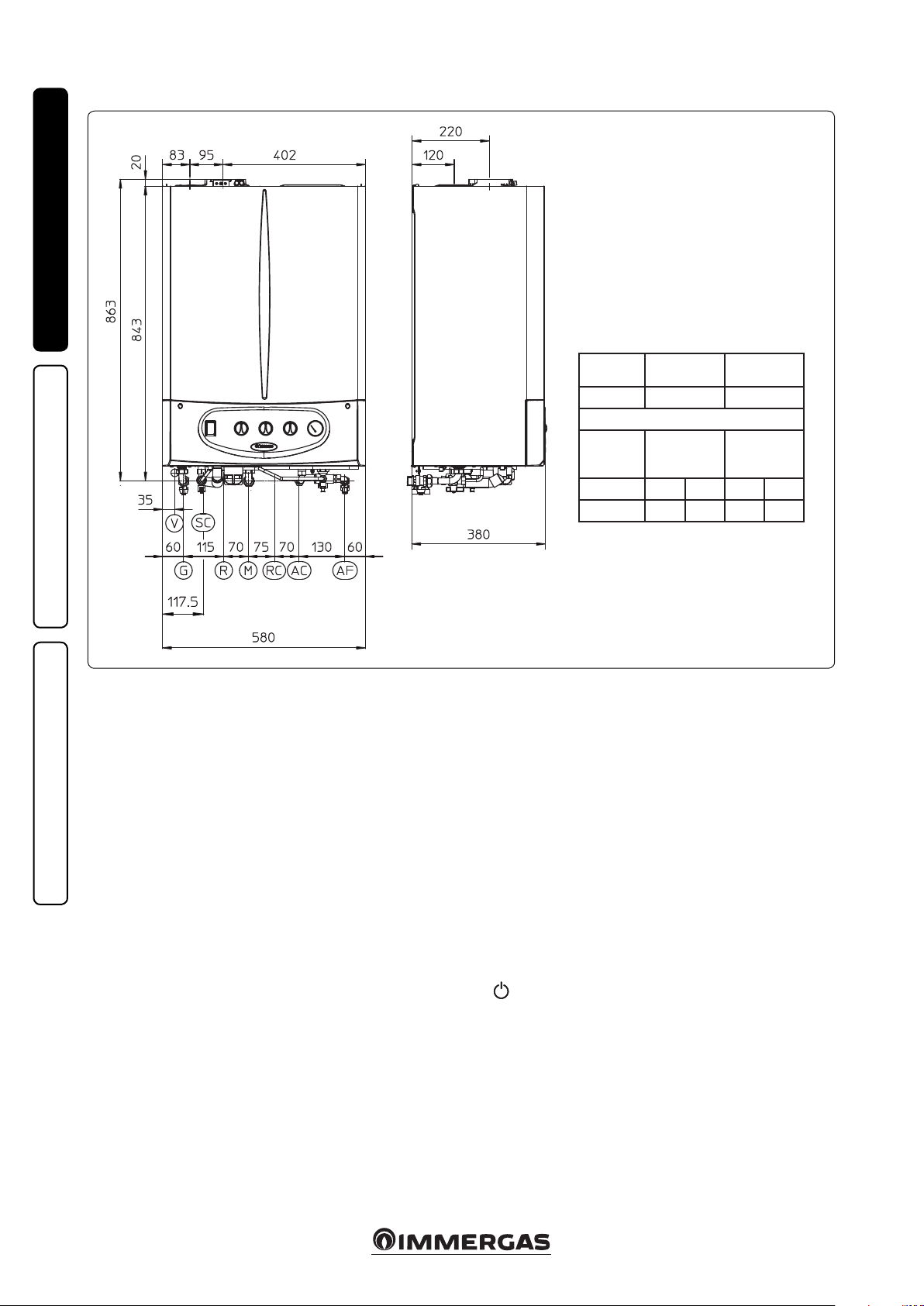
1.2 MAIN DIMENSIONS.
INSTALLERUSER
Key:
V - Electrical connection
G - Gas supply
SC - Condensate drain (minimum internal
diameter 13 mm Ø)
R - System return
M - System ow
RC - Domestic hot water recirculation
(optional)
AC - Domestic hot water outlet
AF - Domestic cold water inlet
N.B.: Connection group (Optional)
1.3 ANTIFREEZE PROTECTION.
Minimum temperature -5°C. e boiler comes
standard with an anti-freeze function that activates the pump and burner when the system
water temperature in the boiler falls below 4°C.
In these conditions the boiler is protected against
freezing to an ambient temperature of -5°C.
Minimum temperature -15°C. In the event the
boiler is installed in a place where the temperature falls below -5°C, the appliance can freeze.
To prevent the risk of freezing follow the instructions below:
- protect the central heating circuit from freezing
MAINTENANCE TECHNICIAN
by inserting a good-quality antifreeze liquid
into this circuit, which is specially suited for
central heating systems and which is manufacturer guaranteed not to cause damage to
the heat exchanger or other components of
the boiler. e antifreeze liquid must not be
harmful to one's health. e instructions of the
manufacturer of this liquid must be followed
scrupulously regarding the percentage necessary with respect to the minimum temperature
at which the system must be kept. An aqueous
solution must be made with potential pollution
class of water 2 (EN 1717:2002).
e materials used for the central heating circuit
of Immergas boilers withstand ethylene and
propylene glycol based antifreeze liquids (if the
mixtures are prepared perfectly).
For life and possible disposal, follow the sup-
plier's instructions.
- Protect the domestic hot water circuit against
freezing by using an accessory that is supplied
on request (anti-freeze kit) comprising two
electric heating elements, the relevant cables
and a control thermostat (carefully read the
installation instructions contained in the accessory kit pack).
In these conditions the boiler is protected against
freezing to temperature of -15°C.
Boiler antifreeze protection (both -5°C and -15°C)
is thus ensured only if:
- the boiler is correctly connected to gas and electricity power supply circuits;
- the boiler is powered constantly;
- the boiler is not in stand-by ( ).
- the boiler is not in anomaly conditions (parag.
2.5);
- the essential components of the boiler and/or
antifreeze kit are not faulty.
Height
(mm)
863 580 380
GAS SYSTEM
1/2” 3/4” 3/4” 1/2” 1/2”
e warranty does not cover damage due to interruption of the electrical power supply and failure
to comply with that stated on the previous page.
NOTE: if the boiler is installed in places where
the temperature falls below 0°C the domestic
hot water and central heating attachment pipes
must be insulated.
Width (mm) Depth (mm)
CONNECTIONS
DOMES-
TIC HOT
WATER
G R M AC AF
1-2
6
1.4 GAS CONNECTION.
Our boilers are designed to operate with methane
gas (G20) and LPG. Supply pipes must be the
same as or larger than the 1/2”G boiler tting.
Before connecting the gas line, carefully clean
inside all the fuel feed system pipes to remove
any residue that could impair boiler eciency.
Also make sure the gas corresponds to that for
which the boiler is prepared (see boiler data
name plate). If dierent, the appliance must be
converted for operation with the other type of
gas (see converting appliance for other gas types).
e dynamic gas supply (methane or LPG) pressure must also be checked according to the type
used in the boiler, which must comply with the
technical standards in force and relevant annexes,
as insucient levels can reduce generator output
and cause malfunctions.
Ensure correct gas cock connection. e gas supply pipe must be suitably dimensioned according
to current regulations in order to guarantee correct gas ow rate to the burner even in conditions
of maximum generator output and to guarantee
appliance eciency (technical specications).
e coupling system must conform to technical
standards in force.
Fuel gas quality. e appliance was designed
to operate with combustible gas free of impurities; otherwise it is advisable to t special lters
upstream of the appliance to restore the purity
of the fuel.
Storage tanks (in case of supply from LPG
depot).
- New LPG storage tanks may contain residual
inert gases (nitrogen) that degrade the mixture
delivered to the appliance casing functioning
anomalies.
- Due to the composition of the LPG mixture,
layering of the mixture components may occur
during the period of storage in the tanks. is
can cause a variation in the heating power of
the mixture delivered to the appliance, with
subsequent change in its performance.
1.5 HYDRAULIC CONNECTION.
Attention: in order not to void the condensa-
tion module warranty, before making the boiler
connections, carefully wash the heating system
(pipes, radiators, etc.) with special pickling or
descaling products to remove any deposits that
could compromise correct boiler operation.
A chemical treatment of the thermal system water is required, in compliance with the technical
standards in force, in order to protect the system
and the appliance from deposits (e.g., lime scale),
slurry or other hazardous deposits.
Water connections must be made in a rational
way using the couplings on the boiler template.
e boiler safety valves outlet must be connected
to a draining funnel. Otherwise, the manufacturer declines any responsibility in case of ooding
if the drain valve cuts in.
Attention: Immergas declines all liability in the
event of damage caused by the inclusion of automatic lling that is not its own brand.
In order to meet the system requirements established by the technical regulation in force in
relation to the pollution of drinking water, we
recommend installing the IMMERGAS antibackow kit to be used upstream of the cold
water inlet connection of the boiler. It is also
recommended that the heat transfer uid (e.g.
water + glycol) entered in the primary circuit
of the boiler (heating circuit), complies with the
local regulations in force.
Attention: to preserve the duration and the efciency features of the appliance, in the presence
of water whose features can lead to the deposit of
scale, installation of the “polyphosphate dispenser”
kit is recommended.
Condensate drain. To drain the condensate
produced by the appliance, it is necessary to
connect to the drainage system by means of acid
condensate resistant pipes, with an internal Ø of
at least 13 mm. e system connecting the appliance to the drainage system must be carried out
in such a way as to prevent freezing of the liquid
contained in it. Before appliance ignition, ensure
that the condensate can be correctly removed.
Aer rst ignition, check that the drain trap is
lled with condensate (para. 1.21). Also, comply
with national and local regulations on discharging waste waters.
1.6 ELECTRICAL CONNECTION.
e boiler has an IPX4D protection rating for the
entire appliance. Electrical safety of the appliance
is reached only when it is correctly connected to
an ecient earthing system as specied by current safety standards.
Attention: Immergas S.p.A. declines any responsibility for damage or physical injury caused by
failure to connect the boiler to an ecient earth
system or failure to comply with the reference
standards.
Also ensure that the electrical installation corresponds to maximum absorbed power specications as shown on the boiler data-plate. Boilers
are supplied complete with an “X” type power
cable without plug. e power supply cable must
be connected to a 230V ±10% / 50Hz mains supply respecting L-N polarity and earth connection;
, this network must also have a multi-pole circuit breaker with class III over-voltage category.
When replacing the power supply cable, contact
a qualied rm (e.g. the Authorised Aer-Sales
Technical Assistance Service). e power cable
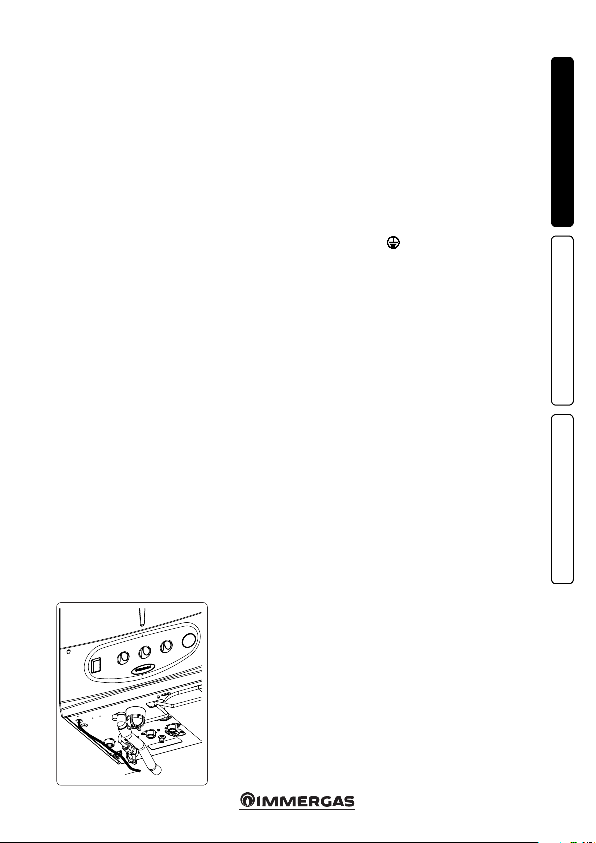
must be laid as shown (Fig. 1-3).
In the event of mains fuse replacement on the
P.C.B., use a 3.15A quick-blow fuse. For the main
power supply to the appliance, never use adapters, multiple sockets or extension leads.
If during connection the L-N polarities are not
respected, the boiler does not detect ame presence and goes into ignition block.
Warning: even where L-N polarity is not complied with, if there is temporary residual voltage
exceeding 30V on the neutral the boiler might
still operate (but only temporarily). Measure the
voltage using appropriate instruments, without
trusting the voltage tester screwdriver.
Installation with system operating at direct
low temperature. e boiler can directly feed a
low temperature system by acting on the jumper
(8 Fig. 3-4) and by setting the ow temperature
adjustment range from 50 ÷ 20°C (Para. 3.17). In
this situation it is good practice to insert a safety
device in series with the power supply and boiler.
is device is made up from a thermostat with
a temperature limit of 60°C. e thermostat
must be positioned on the system delivery pipe
at a distance of at least 2 metres from the boiler.
INSTALLERUSER
CAVO
SUPPLY
ALIMENTAZIONE
VOLTAGE CABLE
MAINTENANCE TECHNICIAN
1-3
7
1.7 REMOTE CONTROLS AND ROOM
CHRONOTHERMOSTATS
OPTIONAL.
e boiler is prepared for the application of room
chrono-thermostats or remote controls, which
are available as optional kits (Fig. 1-4).
All Immergas chrono-thermostats are connected
with 2 wires only. Carefully read the user and
assembly instructions contained in the accessory kit.
• On/O Immergas digital chrono-thermostat.
e chrono-thermostat allows:
INSTALLERUSER
- set two room temperature value: one for
daytime (comfort temperature) and one for
night-time (reduced temperature);
- set a weekly program with four daily switch
on and switch o times;
- select the required operating mode from the
various possible alternatives:
• manual operation (with adjustable tempera-
ture).
• automatic operation (with set programme).
• forced automatic operation (momentarily
changing the temperature of the automatic
programme).
e chrono-thermostat is powered by two 1.5V
LR 6 type alkaline batteries.
• Comando Amico Remoto Remote Control De-
V2
(CARV2) with climate chrono-thermostat
vice
function. In addition to the functions described
in the previous point, the CAR
V2
the user to control all the important information regarding operation of the appliance and
the heating system with the opportunity to easily intervene on the previously set parameters,
without having to go to where the appliance
is installed. e panel is provided with selfdiagnosis to display any boiler functioning
anomalies. The climate chrono-thermostat
incorporated into the remote panel enables
the system ow temperature to be adjusted to
the actual needs of the room being heated, in
order to obtain the desired room temperature
with extreme precision and therefore with
evident saving in running costs. e CAR
panel enables
V2
is
fed directly by the boiler by means of the same 2
wires used for the transmission of data between
the boiler and device.
Important: If the system is divided into zones
using the relevant kit, the CAR
V2
must be used
with its climate thermostat function disabled, i.e.
it must be set to On/O mode.
Comando Amico Remoto Remote Control
V2
or On/O chrono-thermostat electrical connections (Optional). e operations described
below must be performed aer having removed
the voltage from the appliance. Any thermostat
or On/O environment chrono-thermostat must
be connected to clamps 40 and 41 eliminating
jumper X40 (Fig. 3-2). Make sure that the On/
O thermostat contact is of the “clean” type, i.e.
independent of the mains voltage, otherwise the
P.C.B. would be damaged. Any Comando Amico
Remoto Remote Control
V2
must be connected to
clamps 42 and 43 eliminating jumper X40 on the
P.C:B., paying attention not to invert the polarity
in the connections (Fig. 3-2).
e boiler can only be connected to one remote
control. e boiler works with the parameters
set on the CAR
V2
only if the boiler main selector
is turned to DHW/Comando Amico Remoto(
).
Important: if the Comando Amico Remoto
Remote Control V2 or any other On/O chronothermostat is used, arrange two separate lines in
compliance with current regulations regarding
electrical systems. No boiler pipes must ever be
used to earth the electric system or telephone
lines. Ensure elimination of this risk before making the boiler electrical connections.
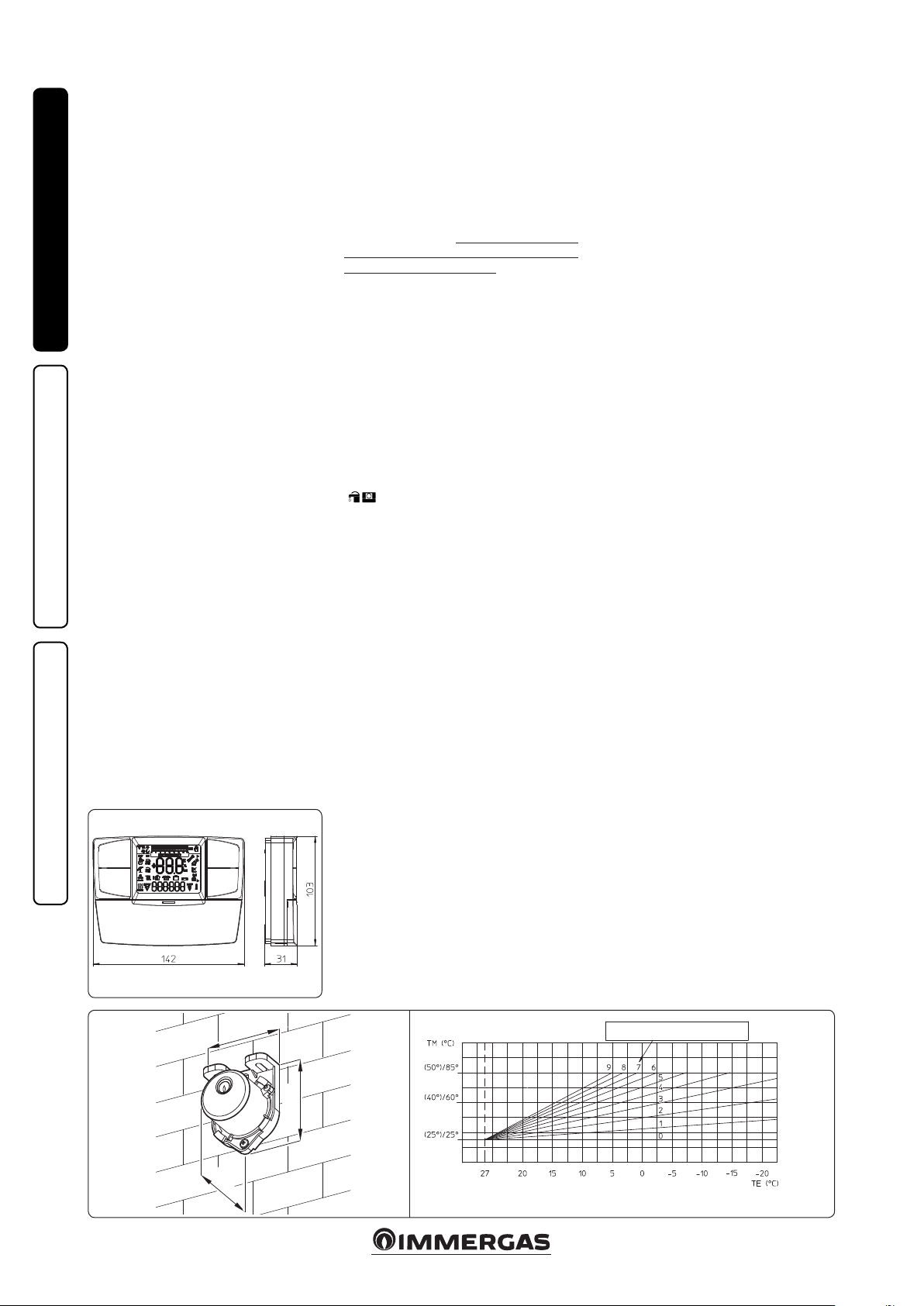
1.8 EXTERNAL TEMPERATURE PROBE
OPTIONAL.
e boiler is designed for the application of the
Room ermostat (Fig. 1-5) which is available
as an optional kit. Refer to the relative instruction sheet for positioning of the external probe.
e probe can be connected directly to the boiler
electrical system and allows the max. system
ow temperature to be automatically decreased
when the external temperature increases, in
order to adjust the heat supplied to the system
according to the change in external temperature.
e external probe always operates when connected, regardless of the presence or type of room
chrono-thermostat used and can work in combination with Immergas chrono-thermostats. e
correlation between system ow temperature
and external temperature is determined by the
position of the central heating selector switch on
the boiler control panel (or on the CARV2 control
panel if connected to the boiler) according to
the curves shown in the diagram (Fig. 1-6). e
electric connection of the external probe must be
made on clamps 38 and 39 on the boiler P.C.B.
(Fig. 3-2).
MAINTENANCE TECHNICIAN
31
45
1-4
58
1-5
Position of the central heating temperature user adjustment
In brackets, temperature value with 25°/50° range
8
1-6
1.9 IMMERGAS FLUE SYSTEMS.
Immergas supplies various solutions separately
from the boilers regarding the installation of
air intake terminals and ue exhaust, which are
fundamental for boiler operation.
Attention: the boiler must be installed exclusively with an original Immergas “Green
Range” inspectionable air intake device and
fumes extraction system made of plastic, as
required by the regulations in force.
e plastic pipes cannot be installed outdoors,
for tracts longer than 40 cm, without suitable
protection from UV rays and other atmospheric agents.
is system can be identied by an identication mark and special distinctive marking
bearing the note: “only for condensing boilers”.
• Resistance factors and equivalent lengths. Each
ue component has a Resistance Factor based
on experimental tests and specied in the table
below. e Resistance Factor for individual
components is independent from the type of
boiler on which it is installed and has a dimensionless size. It is however, conditioned by the
temperature of the uids that pass through the
pipe and therefore, varies according to applications for air intake or ue exhaust. Each single
component has a resistance corresponding to
a certain length in metres of pipe of the same
diameter; the so-called equivalent length,
can be obtained from the ratio between the
relative Resistance Factors. All boilers have an
experimentally obtainable maximum Resistance
Factor equal to 100. e maximum Resistance
Factor allowed corresponds to the resistance
encountered with the maximum allowed pipe
length for each type of Terminal Kit. This
information allows calculations to be made to
verify the possibility of setting up various ue
congurations.
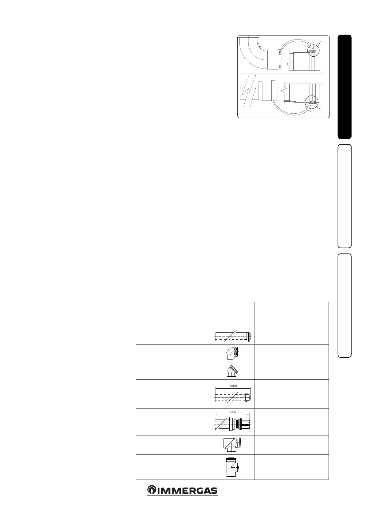
• Positioning the gaskets (black) for “green
range” ue systems. Position the gasket correctly (for bends and extensions) (Fig. 1-7):
- gasket (A) with notches, to use for bends;
- gasket (B) without notches, to use for exten-
sions;
N.B.: if necessary, to ease the push-fitting,
spread the elements with commonly-used talc.
• Coupling extension pipes and concentric
elbows. To install push-tting extensions with
other elements of the ue, proceed as follows:
Install the concentric pipe or elbow with the
male side (smooth) on the female side (with lip
seal) to the end stop on the previously installed
element in order to ensure sealing eciency of
the coupling.
Attention: if the exhaust terminal and/or
concentric extension pipe needs shortening,
consider that the internal duct must always
protrude by 5 mm with respect to the external
duct.
• N.B.: for safety purposes, do not obstruct the
boiler intake/exhaust terminal, even temporaril y.
• N.B.: when installing horizontal pipes, a mini-
mum inclination of 3% must be maintained and
a section clip with pin must be installed every
3 metres.
1.10 TABLES OF RESISTANCE FACTORS
AND EQUIVALENT LENGTHS.
TYPE OF DUCT
Concentric pipe Ø 80/125 m 1
Concentric bend 90° Ø 80/125
Concentric bend 45° Ø 80/125
1-7
Resistance
Factor
(R)
2.1
3.0
2.1
(A)
(B)
Equivalent length
in m of concentric
pipe Ø 80/125
1
1.4
1
INSTALLERUSER
MAINTENANCE TECHNICIAN
Terminal complete with concentric
horizontal intake-exhaust Ø 80/125
Terminal complete with concentric
vertical intake-exhaust Ø 80/125
Concentric bend 90° Ø 80/125 with
inspection
Stub pipe with inspection Ø 80/125
9
2.8
3.6
3.4
3.4
1.3
1.7
1.6
1.6

TYPE OF DUCT
Resistance
Factor
(R)
Equivalent length
in m of concentric
pipe Ø 60/100
Equivalent
length in metres
of pipe Ø 80
Equivalent length
in metres of pipe
Ø 60
Equivalent length
in m of concentric
pipe Ø 80/125
Concentric pipe Ø 60/100
m 1
Concentric bend 90° Ø
60/100
Concentric bend 45° Ø
INSTALLERUSER
60/100
Terminal complete with
concentric horizontal
intake-exhaust Ø 60/100
Concentric horizontal
intake- exhaust terminal
Ø 60/100
Terminal complete with
concentric vertical intakeexhaust Ø 60/100
Concentric vertical intakeexhaust terminal Ø 60/100
Pipe Ø 80 m 1
Complete intake terminal
Ø 80 m 1
Intake terminal Ø 80
Exhaust terminal Ø 80
Bend 90° Ø 80
Bend 45° Ø 80
Pipe Ø 60 m 1 for ducting
Bend 90° Ø 60 for ducting
Reduction Ø 80/60
MAINTENANCE TECHNICIAN
Terminal complete with
exhaust
vertical Ø 60 for ducting
Intake and
Exhaust 6.4
Intake and
Exhaust 8.2
Intake and
Exhaust 6.4
Intake and
Exhaust 15
Intake and
Exhaust 10
Intake and
Exhaust 16.3
Intake and
Exhaust 9
Intake 0.87 m 0.1 Intake m 1.0
Exhaust 1.2 m 0.2 Exhaust m 1.0
Intake 3 m 0.5 Intake m 3.4 Exhaust m 0.9 m 1.4
Intake 2.2 m 0.35 Intake m 2.5
Exhaust 1.9 m 0.3 Exhaust m 1.6
Intake 1.9 m 0.3 Intake m 2.2
Exhaust 2.6 m 0.4 Exhaust m 2.1
Intake 1.2 m 0.2 Intake m 1.4
Exhaust 1.6 m 0.25 Exhaust m 1.3
Exhaust 3.3 m 0.5
Exhaust 3.5 m 0.55
Intake and
Exhaust 2.6
Exhaust 12.2 m 1.9
m 1
m 1.3
m 1
m 2.3
m 1.5
m 2.5
m 1.4
m 0.4
Intake m 7.3
Exhaust m 5.3
Intake m 9.4
Exhaust m 6.8
Intake m 7.3
Exhaust m 5.3
Intake m 17.2
Exhaust m 12.5
Intake m 11.5
Exhaust m 8.3
Intake m 18.7
Exhaust m 13.6
Intake m 10.3
Exhaust m 7.5
Intake 3.8
Exhaust 2.7
Intake 4.0
Exhaust 2.9
Intake m 3.0
Exhaust m 2.1
Intake m 14
Exhaust m 10.1
Exhaust m 1.9 m 3.0
Exhaust m 2.5 m 3.9
Exhaust m 1.9 m 3.0
Exhaust m 4.5 m 7.1
Exhaust m 3.0 m 4.7
Exhaust m 4.9 m 7.7
Exhaust m 2.7 m 4.3
Exhaust m 0.4
Exhaust m 0.6
Exhaust m 0.8
Exhaust m 0.5
Exhaust m 1.0 m 1.5
Exhaust m 1.1 m 1.6
Exhaust m 0.8 m 1.2
Exhaust m 3.7 m 5.8
m 0.4
m 0.5
m 1
m 0.9
m 0.9
m 1.2
m 0.5
0.7
10
1.11 OUTDOOR INSTALLATION IN A
PARTIALLY PROTECTED AREA.
N.B.: a partially protected location is one in which
the appliance is not exposed to the direct action of
the weather (rain, snow, hail, etc..).
is type of installation is only possible when
permitted by the laws in force in the appliance's
country of destination.
• Conguration type B, open chamber and
forced draught.
Using the special coverage kit one can achieve
direct air intake (Fig. 1-8) and fumes exhaust in
a single ue or directly outside. In this conguration it is possible to install the boiler in a partially
protected place. In this conguration the boiler
is classied as type B
With this conguration:
- air intake takes place directly from the envi-
ronment in which the appliance is installed
(outside);
- the fumes exhaust must be connected to its own
single ue (B23) or ducted directly outside via
a vertical terminal for direct exhaust (B53) or
via an Immergas ducting system (B53).
The technical regulations in force must be
respected.
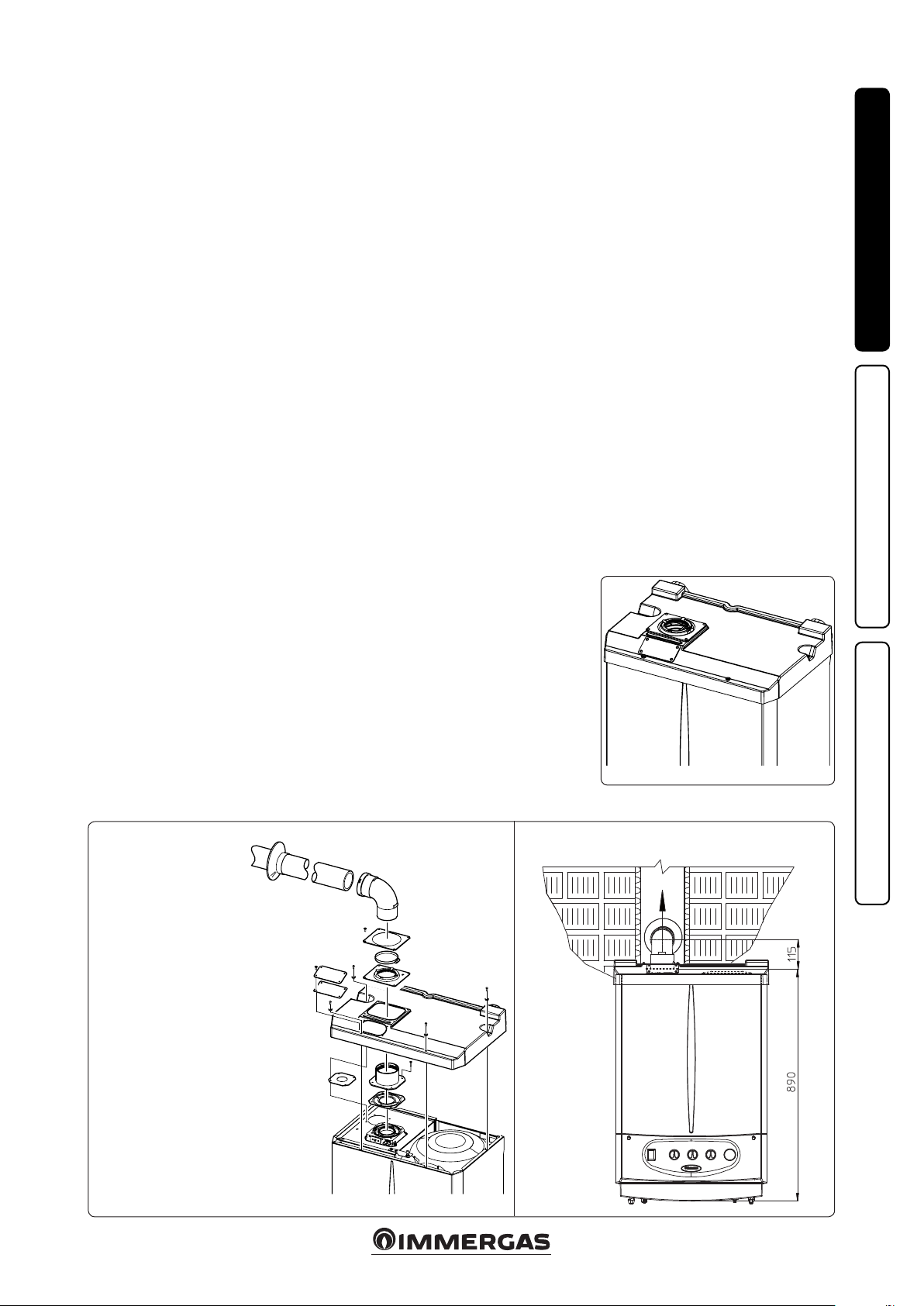
• Coverage kit assembly (Fig. 1-9). Remove
the cap and gasket from the intake hole. Install
the Ø 80 outlet ange on the central hole of the
boiler, taking care to insert the gasket supplied
with the kit and tighten by means of the screws
provided. Place diaphragm Ø 41 on the intake
hole. Install the upper cover, xing it using
the 4 screws present in the kit, positioning the
relevant gaskets. Engage the 90° Ø 80 bend with
the male end (smooth) in the female end (with
lip seal) of the Ø 80 ange unit until it reaches
the end stop. Introduce the gasket, making it
run along the bend. Fix it using the metal-sheet
steel plate and tighten by means of the clip present in the kit, making sure to block the 4 gasket
aps. Fit the male end (smooth) of the exhaust
terminal into the the female end of the bend 90°
Ø 80, making sure that the relevant wall sealing
plate is already tted; this will ensure hold and
joining of the elements making up the kit.
.
23
Max. length of exhaust duct. e ue pipe (both
vertical or horizontal) can be extended to a max.
length of 30 linear metres.
• Coupling of extension pipes. To install push-
tting extensions with other elements of the
ue, proceed as follows: Couple the pipe or
elbow with the male side (smooth) in the female side (with lip seal) to the end stop on the
previously installed element. is will ensure
sealing eciency of the coupling.
• Conguration without cover kit in a partially
protected location (type C boiler)
By leaving the side plugs tted it is possible
to install the appliance externally without the
cover kit. Installation takes place using the
Ø60/100 and Ø 80/125 concentric intake/
exhaust kits. Refer to the paragraph on indoor
installation. In this conguration the upper
cover kit assures additional protection for the
boiler. It is recommended but not compulsory.
INSTALLERUSER
1-8
e cover kit includes:
1 ermoformed cover
1 Ø 41 Intake diaphragm
N°1 Gasket clamping plate
N°1 Gasket
N°1 Gasket tightening strap
e terminal kit includes:
N° 1 Gasket
N° 1 Discharge ange Ø 80
N° 1 Bend 90° Ø 80
N° 1 Drain pipe Ø 80
N° 1 Wall sealing plate
1-101-9
MAINTENANCE TECHNICIAN
11

1.12 CONCENTRIC HORIZONTAL KIT
INSTALLATION.
Type C configuration, sealed chamber and
fan assisted.
e position of the terminal (in terms of distances from openings, overlooking buildings,
floor, etc.) must be in compliance with the
regulations in force.
is terminal is connected directly to the outside
of the building for air intake and ue exhaust. e
horizontal kit can be installed with the rear, right
INSTALLERUSER
side, le side or front outlet. For installation with
frontal outlet, one must use the xing plate and
a concentric bend coupling in order to ensure
sucient space to carry out the tests required
by law upon commissioning.
• External grid. Both the Ø 60/100 and Ø 80/125
intake/exhaust terminal, if properly installed, is
pleasant to look at on the outside of the building. Make sure that the external silicone wall
sealing plate is properly inserted in the wall.
N.B.: for proper system operation the terminal
with grid must be installed correctly ensuring
that, the "high" indication on the terminal is
observed during installation.
Horizontal intake-exhaust kit Ø 60/100 Kit
assembly (Fig. 1-11): install the bend with ange
(2) on the central hole of the boiler, positioning
gasket (1) with the circular projections downwards in contact with the boiler flange, and
tighten using the screws present in the kit. Fit
the Ø 60/100 (3) concentric terminal pipe with
the male side (smooth) to the female side of the
bend (2) up to the end stop; making sure that the
internal and external wall sealing plate have been
tted, this will ensure sealing and joining of the
elements making up the kit.
• Extensions for Ø 60/100 horizontal kit (Fig.
1-12). e kit with this conguration can be
extended up to a max. 12.9 horizontal m in-
cluding the terminal with grid and excluding
the concentric bend leaving the boiler. is
conguration corresponds to a resistance factor
of 100. In this case the special extensions must
be requested.
Immergas also provides a Ø 60/100 simplied
terminal, which in combination with its extension kits allows you to reach a maximum extension of 11.9 metres.
Horizontal intake-exhaust kit Ø 80/125 Kit
assembly (Fig. 1-13): to install the kit Ø 80/125
one must use the anged adapter kit in order
to install the ue system Ø 80/125. Install the
anged adaptor (2) on the central hole of the
boiler, positioning gasket (1) with the circular
projections downwards in contact with the boiler
ange, and tighten using the screws contained in
the kit. Engage the bend (3) with the male side
(smooth) to the end stop on the adapter (1). Fit
the Ø 80/125 (5) concentric terminal pipe with
the male side (smooth) to the female side of the
bend (4) (with lip seals) up to the end top; making
sure that the internal (6) and external wall sealing
plate (7) have been tted, this will ensure sealing
and joining of the elements making up the kit.
• Extensions for horizontal kit Ø 80/125 (Fig.
1-14). e kit with this conguration can be
extended up to a max. length of 32 m, including the terminal with grid and excluding the
concentric bend leaving the boiler. If additional components are assembled, the length
equivalent to the maximum allowed must be
subtracted. In this case the special extensions
must be requested.
2
1
3
4
e kit includes:
N° 1 - Gasket (1)
N° 1 - Concentric bend Ø 60/100 (2)
N° 1 - Int./exhaust concentric terminal Ø 60/100 (3)
N° 1 - Internal wall sealing plate (4)
N° 1 - External wall sealing plate (5)
MAINTENANCE TECHNICIAN
3
2
4
5
1
e adaptor kit includes:
N° 1 - Gasket (1)
N° 1 - Adaptor Ø 80/125 (2)
1-13
C
13
5
C
13
6
e Kit Ø 80/125 includes:
N° 1 - Concentric bend Ø
80/125 a 87° (3)
N° 1 - Int./exhaust concentric
terminal Ø 80/125 (4)
N° 1 - Internal wall sealing
plate (5)
N° 1 - External wall sealing
plate (6)
e remaining kit components
must not be used
C
13
Max 12900 mm
Max 12790 mm
1-11 1-12
C
13
Max 32000 mm
Max 31956 mm
1-14
12
 Loading...