

Page 1
Instructions and
*1.042022ENG*
recommendations
Installer
User
Maintenance technician
IE
VICTRIX ZEUS
25
Page 2

Page 3

INDEX
Dear Customer, ................................................................................. 3
General recommendations .............................................................. 3
Safety symbols used. ......................................................................... 5
Personal protective equipment. ...................................................... 5
1 Boiler installation................................................................. 6
1.1 Installation recommendations. .......................................... 6
1.2 Main dimensions. ................................................................ 9
1.3 Minimum installation distances. ....................................... 9
1.4 Antifreeze protection. .......................................................10
1.5 Boiler connection unit. ..................................................... 11
1.6 Gas connection. ................................................................. 11
1.7 Hydraulic connection. ....................................................... 12
1.8 Electrical connection. ........................................................ 13
1.9 Remote controls and room chrono-thermostats
(Optional). .......................................................................... 13
1.10 External temperature probe (Optional). ......................... 14
1.11 Immergas ue systems. ..................................................... 15
1.12 Tables of resistance factors and equivalent lengths of
“green range” ue system components. .......................... 16
1.13 Outdoor installation in partially protected area. ........... 18
1.14 Concentric horizontal kit installation. ............................ 20
1.15 Concentric vertical Kit installation. ................................ 21
1.16 Separator kit installation. .................................................. 22
1.17 Adaptor C9 kit installation. .............................................. 24
1.18 Ducting of ues or technical slots. ..................................26
1.19 Conguration type B, open chamber and fan assisted for
indoors. ............................................................................... 26
1.20 Flue exhaust to ue/chimney............................................ 27
1.21 Flues, chimneys and chimney caps. ................................27
1.22 Water treatment system lling. ........................................ 28
1.23 System lling. ..................................................................... 28
1.24 Filling the condensate drain trap. .................................... 28
1.25 Gas system start-up. ..........................................................28
1.26 Boiler start-up (Ignition). ................................................. 29
1.27 Circulation pump. .............................................................. 30
1.28 Kits available on request. .................................................. 31
1.29 Boiler components. ............................................................32
2 Instructions for use and maintenance. ............................33
2.1 General warnings. .............................................................. 33
2.2 Cleaning and maintenance. .............................................. 35
2.3 Control panel. .....................................................................35
2.4 Using the boiler. ................................................................. 36
2.5 Fault and anomaly signals. ............................................... 37
2.6 Information Menu. ............................................................ 40
2.7 Boiler shutdown. ................................................................ 40
2.8 Restore central heating system pressure. ........................ 40
2.9 Draining the system. ......................................................... 40
2.10 Draining the domestic hot water circuit. ........................ 40
2.11 Storage tank draining. ....................................................... 41
2.12 Antifreeze protection. .......................................................41
2.13 Cleaning the case. .............................................................. 41
2.14 Decommissioning. ............................................................. 41
2.15 Gas system not used for periods over 12 months. ......... 41
3 Instructions for maintenance and initial check. ............ 42
3.1 General warnings. .............................................................. 42
3.2 Initial check. ....................................................................... 42
3.3 Yearly appliance check and maintenance. ......................43
3.4 Hydraulic Diagram. ........................................................... 44
3.5 Wiring diagram. .................................................................45
3.6 Removable memory .......................................................... 46
3.7 Troubleshooting. ................................................................ 46
3.8 Converting the boiler to other types of gas. ................... 47
3.9 Checks following conversion to another type of gas. ....47
3.10 Calibration type involving the replacement of a
component. ......................................................................... 48
3.11 Complete calibration function. ........................................ 48
3.12 CO2 adjustment. ................................................................ 49
3.13 Fast calibration. .................................................................. 49
3.14 Flue test. .............................................................................. 50
3.15 Programming the P.C.B. ................................................... 50
3.16 "Chimney sweep” function. .............................................. 54
3.17 Pump anti-block function. ............................................... 54
3.18 ree-way anti-block system............................................ 54
3.19 Radiators antifreeze function. .......................................... 54
3.20 Periodical P.C.B. self-check. ............................................. 54
3.21 Automatic vent function. .................................................. 54
3.22 Casing removal...................................................................55
4 Technical data..................................................................... 57
4.1 Variable heat output. .........................................................57
4.2 Combustion parameters. ..................................................57
4.3 Technical data table. .......................................................... 58
4.4 Key for Data nameplate..................................................... 59
4.5 Technical parameters for combination boilers
(in compliance with Regulation 813/2013). ................... 60
4.6 Product che
(in compliance with Regulation 811/2013). ................... 61
4.7 Parameters for lling in the package che. .................... 62
33
Page 4

Dear Customer,
Our compliments for having chosen a top-quality Immergas product, able to ensure well-being and safety for a long period of time. As an
Immergas Customer, you can also count on a qualied aer-sales service, prepared and updated to guarantee constant eciency of your
boiler. Read the following pages carefully: you will be able to draw useful tips on the correct use of the device, compliance of which will
conrm your satisfaction with the Immergas product.
For assistance and routine maintenance, contact Authorised Immergas Service Centres: they have original spare parts and are specically
trained directly by the manufacturer.
GENERAL RECOMMENDATIONS
is book contains important information for the:
Installer (section 1);
User (section 2);
Maintenance Technician (section 3).
• e user must carefully read the instructions in the specic section (section 2).
• e user must limit operations on the appliance only to those explicitly allowed in the specic section.
• e appliance must be installed by qualied and professionally trained personnel.
• e instruction booklet is an integral and essential part of the product and must be given to the new user in the case of transfer or
succession of ownership.
• It must be stored with care and consulted carefully, as all of the warnings provide important safety indications for installation, use
and maintenance stages.
• In compliance with the legislation in force, the systems must be designed by qualied professionals, within the dimensional limits
established by the Law. Installation and maintenance must be performed in compliance with the regulations in force, according to
the manufacturer's instructions and by professionally qualied sta, meaning sta with specic technical skills in the plant sector,
as provided for by Law.
• Improper installation or assembly of the Immergas device and/or components, accessories, kits and devices can cause unexpected
problems for people, animals and objects. Read the instructions provided with the product carefully to ensure proper installation.
• is instructions manual provides technical information for installing Immergas products. As for the other issues related to the
installation of products (e.g. safety at the workplace, environmental protection, accident prevention), it is necessary to comply with
the provisions of the standards in force and the principles of good practice.
• All Immergas products are protected with suitable transport packaging.
• e material must be stored in a dry place protected from the weather.
• Damaged products must not be installed.
• Maintenance must be carried out by skilled technical sta. For example, the Authorised Immergas Service Centre that represents a
guarantee of qualications and professionalism.
• e device must only be destined for the use for which it has been expressly declared. Any other use will be considered improper
and therefore potentially dangerous.
• If errors occur during installation, operation and maintenance, due to non-compliance with technical laws in force, standards or
instructions contained in this booklet (or however supplied by the manufacturer), the manufacturer is excluded from any contractual
and extra-contractual liability for any damages and the device warranty is invalidated.
e company IMMER
facturing and aer-sales assistance processes comply with the requirements of standard UNI EN ISO 9001:2015.
For further details on the product CE marking, request a copy of the Declaration of Conformity from the manufacturer, specifying the
appliance model and the language of the country.
e manufacturer declines all liability due to printing or transcription errors, reserving the right to make any modications to its
t
echnical and commercial documents without forewarning.
44
GAS S.p.A., with registered oce in via Cisa Ligure 95 42041 Brescello (RE), declares that the design, manu-
Page 5
SAFETY SYMBOLS USED.
GENERIC HAZARD
Strictly follow all of the indications next to the pictogram. Failure to follow the indications can generate hazard situations resulting in possible harm to the health of the operator and user in general.
ELECTRI
Strictly follow all of the indications next to the pictogram. e sym
CAL HAZARD
bol indicates the appliance’s electrical components
or, in this manual, identies actions that can cause an electrical hazard.
M
OVING PARTS
e symbol indicates the appliance’s moving components that can cause hazards.
OT SURFACES
H
e symbol indicates the appliance’s very hot components that can cause burns.
HARP SURFACES
S
e symbol indicates the appliance’s components or parts that can cause cuts if touched.
EARTH TERMINAL CONNECTION
e symbol identies the appliance’s earth terminal connection point.
READ AND UNDERSTAND THE INSTRUCTIONS
Read and understand the appliance’s instructions before performing any operation, carefully following the indications
provided.
INFORMATION
Indicates useful tips or additional information.
RECOVERABLE OR RECYCLABLE MATERIAL
e user must not dispose of the appliance at the end of its service life as municipal waste, but send it to appropriate collection centres.
PERSONAL PROTECTIVE EQUIPMENT.
SAFETY GLOVES
SAFETY GOGGLES
SAFETY FOOTWEAR
55
Page 6
BOILER INSTALLATION.
1
1.1 INSTALLATION RECOMMENDATIONS.
ATTENTION:
operators who install and service the
appliance must wear the personal protective equipment required by applica-
INSTALLER
ble law.
SI
YES
NO
NO
1
e Victrix Zeus 25 boiler has been designed for wall
mounted installation only; for heating and production
of domestic hot water for domestic use and similar
purposes.
e place of installation of the appliance and relative
Immergas accessories must have suitable features
(technical and structural), such as to allow for (always in safe,
ecient and comfortable conditions):
USER
- installation (according to the provisions of technical legislation
and technical regulations);
- maintenance operations (including scheduled, periodic, routine and special maintenance);
- removal (to outdoors in the place for loading and transporting
the appliances and components) as well as the eventual replacement of those with appliances and/or equivalent components.
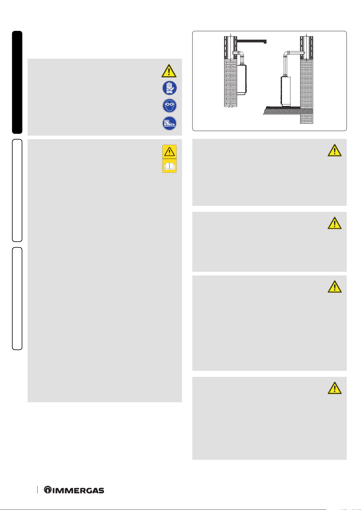
e wall surface must be smooth, without any protrusions or
r
ecesses enabling access to the rear part. ey are not designed
to be installed on plinths or oors (Fig. 1).
By varying the type of installation the classication of the boiler
also varies, precisely:
- Typ e B23 or B53 boiler if installed using the relevant terminal
for air intake directly from the room in which the boiler has
been installed.
- Type C boiler if installed using concentric pipes or other types
of pipes envisioned for the sealed chamber boiler for intake of
air and expulsion of ue gas.
Only professionally enabled companies are authorised to install
MAINTENANCE TECHNICIAN
Immergas gas appliances.
Installation must be carried out according to regulation standards, current legislation and in compliance with local technical
regulations and the required technical procedures.
ATTENTION:
it is not permitted to install boilers that
are removed and decommissioned from
other systems. e m
anufacturer declines all
liability for damages caused by boilers removed
from other systems or for any non-conformities
of such equipment.
ATTENTION:
check the environmental operating
conditions of all parts relevant to installation, referring to the values shown in the
technical data table in this booklet.
ATTENTION:
Installation of the Victrix Zeus 25 boiler
when powered by LPG must comply with
the rules regarding gases with a greater density
than air (remember, as an example, that it is
prohibited to install plants powered with the
above-mentioned gas in rooms where the oor
is at a lower quota than the country level).
ATTENTION:
if installing a kit or servicing the appliance, always empty the system’s
domestic hot water circuit rst so as not to
compromise the appliance’s electrical safety
(see Par. 2.9 and 2.10).
6
6
Page 7
Before installing the appliance, ensure that it is delivered in perfect condition; if in doubt, contact the
supplier immediately. Packing materials (staples, nails,
plastic bags, polystyrene foam, etc.) constitute a hazard
and must be kept out of the reach of children.
If the appliance is installed inside or between cabinets,
ensure suci
advisable to leave clearance of at least 3 cm between the boiler
casing and the vertical sides of the cabinet. Leave adequate
space above the boiler for possible water and ue removal
connections (Fig. 3).
It is just as important that the intake grids and exhaust
terminals are not obstructed.
It is recommended to check that no ue gas recirculation is found in the air sample points (0.5% maximum
permitted CO2).
Keep all ammable objects away from the appliance
(paper, rags, plastic, polystyrene, etc.).
e minimum distance for exhaust pipes from am-
mable materials must be at least 25 cm.
Do not place household appliances underneath the boiler as they
could be damaged if the safety valve intervenes, if the drain trap
is blocked, or if there are leaks from the hydraulic connections;
otherwise, the manufacturer cannot be held responsible for any
damage caused to the household appliances.
For the aforementioned reasons, we recommend not placing
furnishings, furniture, etc. under the boiler.
In the event of malfunctions, faults or incorrect operation,
turn the appliance o immediately and contact an authorised
company (e.g. the Immergas Technical Assistance centre, which
has specically trained sta and original spare parts). Do not
attempt to modify or repair the appliance alone.
Any modication to the appliance that is not explicitly indicated
in this section of the booklet is forbidden.
ent space for normal servicing; therefore it is
Installation Standards:
- this boiler can be installed outdoors in
a partially protected area. A partially
protected area is one in which the boiler is
not exposed to the direct action of the weather
(rain, snow, hail, etc.).
is type of installation is only possible when
permitted by the laws in force in the appliance's
country of destination.
- Installation of gas appliances, ue exhaust
pipes and combustion air intake pipes is forbidden in places with a re risk (for example:
garages, closed parking stalls), and in potentially dangerous places.
- Installation is prohibited on the vertical projection of the cooking surface.
- Installation is forbidden in places/
rooms that constitute public areas of apartment buildings, internal stairways or other
escape routes (e.g. o
or landings, entrance
halls, etc.).
- Installation is also forbidden in places/rooms
that constitute public areas of apartment
buildings such as cellars, entrance halls, attics, los, etc., unless otherwise provided for
by local regulations in force.
INSTALLER
USER
- ese boilers are not suitable for installation
on walls made of combustible material.
N.B.: wall mounting of the boiler must guarantee
stable and ecient support for the boiler. e plugs
(standard supply) are only to be used to x the boiler
to the wall; they only ensure adequate support if
inserted correctly (according to technical standards)
in walls made of solid or semi-hollow brick or block.
In the case of walls made from hollow brick or block,
partitions with limited static properties, or in any case walls
other than those indicated, a static test must be carried out to
ensure adequate support.
MAINTENANCE TECHNICIAN
77
Page 8
ese boilers are used to heat water to below boiling
emperature in atmospheric pressure.
t
ey must be connected to a central heating system
and domestic hot water circuit suited to their performance and capacity.
Risk of damage due to corrosion caused by unsuitable
combustion air and environment.
INSTALLER
Spray, solvents, chlorine-based detergents, paints, glue,
ammonium compounds, powders and similar cause
product and ue duct corrosion.
- Check that combustion air power supply is free from
chlorine, sulphur, powders, etc.
- Make sure that no chemical substances are stored in the place
of installation.
- If you want to install the product in beauty salons, paint
workshops, carpenter’s shop, cleaning companies or
similar, choose a separate installation area that ensures
combustion air supply that is free from chemical substances.
- Make sure the combustion air is not fed from chimneys that were
used with gas boilers or other heating devices. In fact, these may
USER
cause an accumulation of soot in the chimney.
Risk of material damage aer using sprays and liquids
to search for leaks
Leak sprays and liquids clog the reference hole P.Ref
(Part. 5 Fig. 37) of the gas valve, damaging it irreparably.
During installation and maintenance, do not use spray
or liquids in the upper area of the gas valve (side referring to the
electric connections)
ATTENTION:
- Type B open chamber boilers must
not be installed in places where commercial, artisan or industrial activities take
place, which use products that may develop
volatile vapours or substances (e.g. acid vapours, glues, paints, solvents, combustibles,
etc.), as well as dusts (e.g. dust deriving from
the working of wood, coal nes, cement, etc.),
which may be damaging for the components
of the appliance and jeopardise functioning.
- Unless otherwise provided for by local regulations in force, congurations B23 and B53: the
boilers must not be installed in bedrooms,
bathrooms or bedsits. ey must neither be
installed in rooms containing solid fuel heat
generators nor in rooms communicating with
said rooms.
- e installation rooms must be permanently
ventilated, in compliance with the local regulations in force (at least 6 cm2 for every kW
of installed heat input, except in the event of
any increases needed for electro-mechanical
vacuum cleaners or other devices that could
put the installation room under vacuum).
-
Installation of appliances in B23 and B53 conguration is recommended in non-residential
premises and which are permanently ventilated.
Filling the condensate drain trap.
On rst lighting of the boiler, ue gas may
come out the condensate drain; aer a
few minutes’ operation check that this no longer
MAINTENANCE TECHNICIAN
occurs. is means that the trap is lled with
condensate to the correct level preventing the
passage of combustion products.
88
ATTENTION:
Failure to comply with the above implies
personal responsibility and invalidates
the warranty.
Page 9
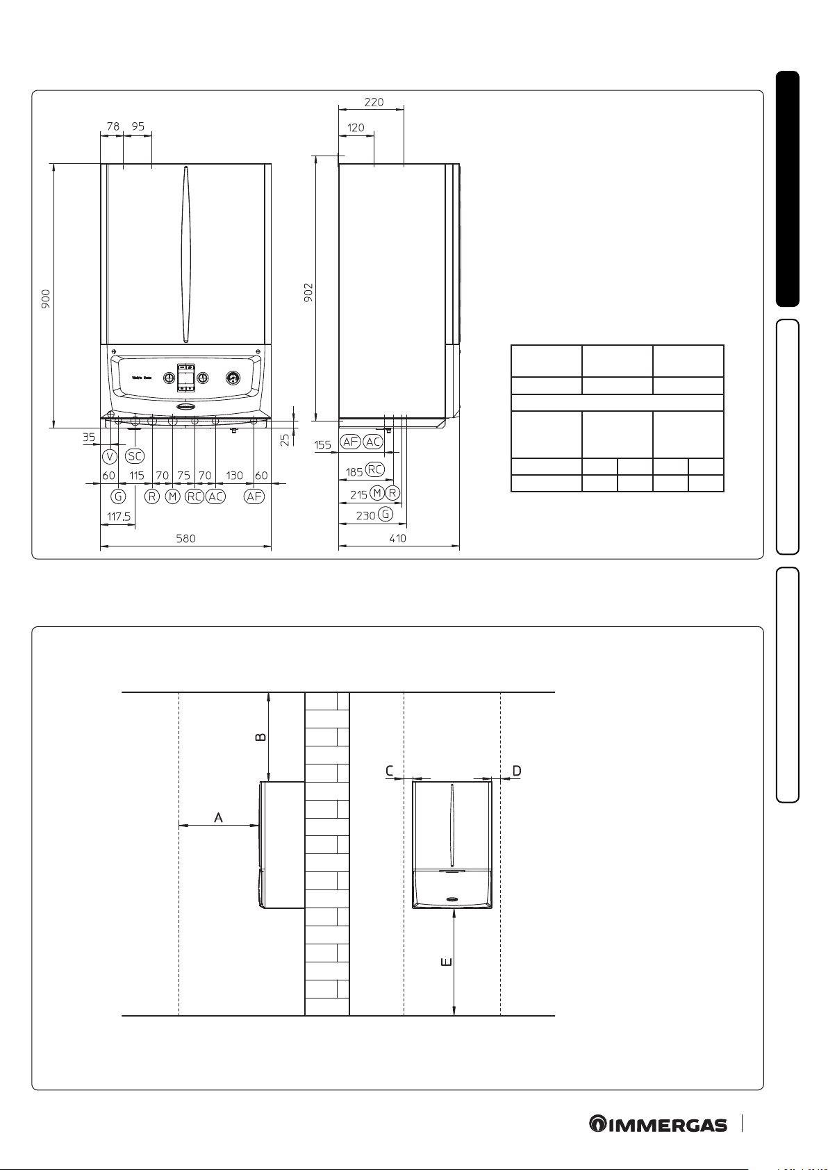
1.2 MAIN DIMENSIONS.
Key:
V - Electrical connection
G - Gas supply
SC - Condensate drain (minimum
internal diameter Ø 13 mm)
R - System return
M - System ow
RC - Domestic hot water pump
(optional)
AC - Domestic hot water outlet
AF - Domestic hot water inlet
INSTALLER
1.3 MINIMUM INSTALLATION DISTANCES.
Height
(mm)
900 580 410
TEMPLATE CONNECTIONS
GAS
G AC AF R M
1/2” 1/2” 1/2” 3/4” 3/4”
Width
(mm)
DOMESTIC
HOT
WATER
Depth
(mm)
SYSTEM
USER
2
Key:
A - 450 mm
B - 350 mm
C - 30 mm
D - 30 mm
E - 350 mm
MAINTENANCE TECHNICIAN
3
99
Page 10
1.4 ANTIFREEZE PROTECTION.
Minimum temperature -15°C. If the boiler is installed
in a place where the temperature drops below 0°C, the
appliance can freeze.
To prevent the risk of freezing follow the instructions
below:
- protect the central heating circuit from freezing by inserting a
good-quality antifreeze liquid into this circuit, which is specially suited for central heating systems and which is manufacturer
INSTALLER
guaranteed not to cause damage to the heat exchanger or other
components of the boiler. e antifreeze liquid must not be
harmful to one's health. e instructions of the manufacturer
of this liquid must be followed scrupulously regarding the percentage necessary with respect to the minimum temperature
at which the system must be kept.
N.B.: the excessive use of glycol could jeopardise the proper
functioning of the appliance.
An aqueous solution must be made with potential pollution
class of water 2 (EN 1717:2002).
e materials used for the central heating circuit of Immergas
boilers resist ethylene and propylene glycol based antifreeze
liquids (if the mixtures are prepared perfectly).
USER
For life and possible disposal, follow the supplier's instructions.
- Protect the domestic hot water circuit against freezing by using
an accessory that is supplied on request (antifreeze kit) comprising two electric heating elements, the relevant wiring and a
control thermostat (carefully read the installation instructions
contained in the accessory kit pack).
In these conditions the boiler is protected against freezing to
temperature of -15°C.
Boiler antifreeze protection (both -5°C and -15°C) is thus ensured only if:
- the boiler is correctly connected to gas and electricity power
supply circuits;
- the boiler is powered constantly;
- the boiler is not in “o ” mode;
- the boiler is not in anomaly conditions (Par. 2.5);
- the essential components of the boiler and/or antifreeze kit are
not faulty.
e warranty does not cover damage due to interruption of the
lectrical power supply and failure to comply with that stated
e
MAINTENANCE TECHNICIAN
on the previous page.
Note: if the boiler is installed in places where the temperature
falls below 0°C the domestic hot water and central heating
attachment pipes and the condensate drain pipe must be
insulated.
Note: the antifreeze systems described in this chapter are
only to protect the boiler. e presence of these functions and
devices does not exclude the possibility of parts of the system
or domestic hot water circuit outside the boiler from freezing.
1010
Page 11
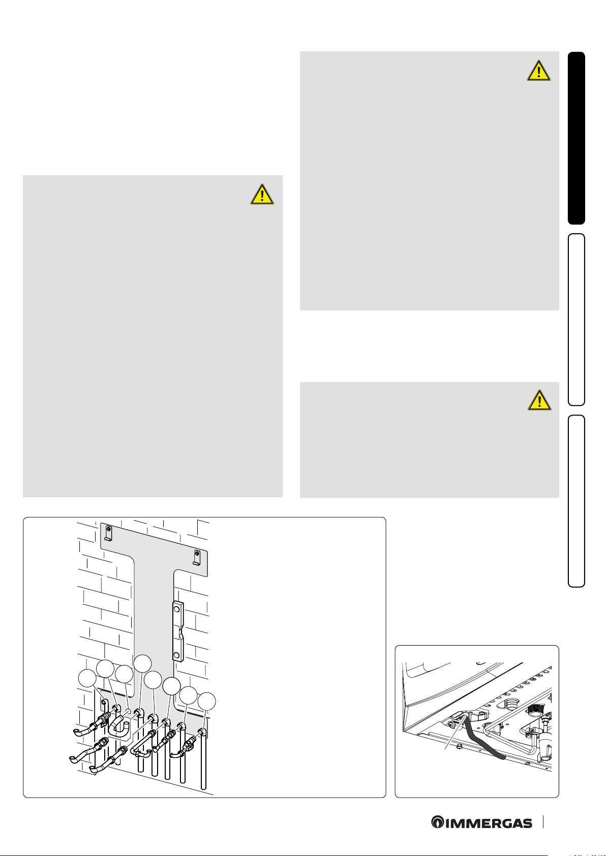
1.5 BOILER CONNECTION UNIT.
e connection unit consisting of all the necessary parts to perform the hydraulic and gas system connections of the appliance
comes as a standard supply. Perform the connections respecting
the layout of (Fig. 4) based on the type of installation to be made.
1.6 GAS CONNECTION.
Our boilers are designed to operate with methane gas (G20) and
L.P.G. Supply pipes must be the same as or larger than the 3/4”G
boiler tting.
ATTENTION:
Before connecting the gas line, carefully
clean inside all the fuel feed system pipes
to remove any residue that could impair boiler
eciency. Also make sure the gas corresponds
to that for which the boiler is prepared (see
boiler data nameplate). If dierent, the boiler
must be converted for operation with the other
type of gas (see converting appliance for other
gas types). It is also important to check the dy-
mic pressure of the mains (metha
na
ne or LPG)
used to supply the boiler, which must comply
with EN 437 and its attachment, as insucient
levels may reduce generator output and cause
discomfort to the user.
According to local regulations in force,
make sure that a gas cock is installed
upstream of each connection between
the appliance and the gas system. is cock,
if supplied by the appliance’s manufacturer,
can be directly connected to the appliance
(i.e. downstream from the pipes connecting
the system to the appliance), according to the
manufacturer’s instructions.
The Immergas connection unit, which is a
standard supply, also includes the gas cock,
whose installation instructions are provided
in the kit.
In any case, make sure the gas cock is connected properly.
e gas supply pipe must be suitably dimensioned according to
current regulations in order to guarantee correct gas ow rate to
the burner even in conditions of maximum generator output and
to guarantee appliance eciency (technical specications). e
coupling system must conform to standards in force (EN 1775).
ATTENTION:
the appliance is designed to operate with
fuel gas free from impurities; otherwise
it is advisable to t special lters upstream of
the appliance to restore the purity of the fuel.
INSTALLER
USER
e kit includes:
N°2 - 3/4” telescopic ttings (R-M)
N°1 - 1/2” telescopic tting (AC)
N°1 - 1/2” gas cock (G)
N°1 - 1/2” ball valve (AF)
N°2 - Ø18 copper bends
N°2 - Ø14 copper bends
N°1 - Pipe Ø 18
N°2 - adjustable expansion bolts
N°2 - boiler support hooks
Gaskets and seal O-Ring
SC
R
M
RC
AC
Key:
V - Electrical connection 230V-50Hz
G - 1/2” gas supply
AF
SC - Condensate draining
R - 3/4” system return
M - 3/4” System ow
RC - 1/2” domestic hot water recirculation
AC - 1/2” domestic hot water outlet
AF - 1/2” domestic hot water inlet
CAVO
POWER
ALIMENTAZIONE
CABLE
4
5
5
G
V
11
11
MAINTENANCE TECHNICIAN
Page 12
Storage tanks (in case of supply from LPG depot).
- New LPG storage tanks may contain residual inert gases (nitrogen) that degrade the mixture delivered to the appliance casing
functioning anomalies.
- Due to the composition of the LPG mixture, layering of the
mixture components may occur during the period of storage in
the tanks. is can cause a variation in the caloric value of the
mixture delivered to the appliance, with subsequent change in
its performance.
INSTALLER
1.7 HYDRAULIC CONNECTION.
In order not to void the condensation module warranty before making the boiler connections, carefully
clean the heating system (pipes, radiators, etc.) with
special pickling or descaling products to remove
any deposits that could compromise correct boiler
operation.
ATTENTION:
the manufacturer declines all liability
in the event of damage caused by the
installation of an automatic lling system.
In order to meet the system requirements established by EN 1717
in terms of pollution of drinking water, we recommend installing
the IMMERGAS anti-backow kit to be used upstream of the cold
water inlet connection of the boiler. We also recommend using a
category 1, 2 or 3 heat transfer uid (ex: water + glycol) in the boil-
er's primary circuit (C.H. circuit), as dened in standard EN 1717.
To preserve the duration of appliance eciency features, in the presence of water whose features can
lead to the deposit of lime scale, installation of the
“polyphosphate dispenser” kit is recommended .
A treatment of the heating and water system water is required,
in compliance with the technical standards in force, in order to
protect the system and the appliance from deposits (e.g. scale),
slurry or other hazardous deposits. In order not to void the heat
USER
exchanger warranty, you are required to comply with what has
been prescribed in (Par. 1.22.
Water connections must be made in a rational way using the
couplings on the boiler template.
3 bar safety valve.
Safety valve (Part. 5 Fig. 32) discharge must always be conveyed
through a draining funnel. Consequently, in the event of valve
intervention, the discharged liquid will end up in the sewer system.
Condensate drain.
To drain the condensate produced by the appliance, it is necessary
to connect to the drainage system by means of acid condensate
resistant pipes, with an internal Ø of at least 13 mm. e system
connecting the appliance to the drainage system must be carried
out in such a way as to prevent occlusion and freezing of the liquid
contained in it. Before appliance ignition, ensure that the condensate can be correctly removed. Aer rst ignition, check that
the drain trap is lled with condensate (Para. 1.24). Also, comply
with national and local regulations on discharging waste waters.
In the event condensate is not discharged into the wastewater
drainage system, a condensate neutraliser must be installed to
ensure compliance with the parameters established by the legislation in force.
MAINTENANCE TECHNICIAN
1212
Page 13
1.8 ELECTRICAL CONNECTION.
e appliance has an IPX5D protection degree; electrical safety of
the appliance is achieved only when it is connected properly to an
ecient earthing system, as specied by current safety standards.
ATTENTION:
the manufacturer declines any responsibility for damage or physical injury
caused by failure to connect the boiler
to an ecient earthing system or failure
to comply with the IEC reference standards.
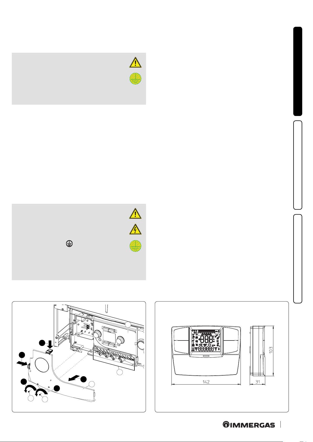
• Open the control panel connections compartment (Fig. 6).
To carry out electrical connections, all you have to do is open
the connections compartment as follows.
- Remove the front panel (Fig. 49).
- Remove the cover (Ref. b Fig. 6).
1) Loosen the two screws (a).
2) Press the two hooks on the cover (b).
3) Remove the cover (b) from the control panel (c).
- At this point, it is possible to access the terminal board (d).
Also ensure that the electrical installation corresponds to maximum absorbed power specications as shown on the boiler data
nameplate. Boilers are supplied complete with an “X” type power
cable without plug.
ATTENTION:
e power supply cable must be connected to a 230V ±10% / 50Hz mains
supply respecting L-N polarity and
earth connection; this network must
also have a multi-pole circuit breaker
with class III overvoltage category in
compliance with installation regulations.
To protect from possible dispersions of DC voltage, it is necessary
to provide a type A dierential safety device.
If the power supply cable is damaged, it must be replaced by a
special cable or assembly, which are only available from the manufacturer or its Aer-sales Service. It is recommended to contact
a qualied company (e.g. the Immergas Authorised Aer-Sales
Technical Assistance Service) for replacement to avoid a hazard.
e power cable must be laid as shown (Fig. 5).
If the network fuse on the connection terminal block needs replacing, this must also be done by qualied personnel: use a 3.15
A fast fuse.
For the main power supply to the appliance, never use adapters,
multiple sockets or extension leads.
Installation with system operating at direct low temperature.
e boiler can directly supply a low-temperature system by setting
the ow temperature adjustment range “t0” and “t1” (Par. 3.15). In
this situation it is good practice to insert a relevant safety kit (optional) made up from a thermostat (with adjustable temperature).
Execute connection to terminal boards 14 and 15, eliminating
jumper X70 (Fig. 36). e thermostat must be positioned on the
system ow pipe at a distance of at least 2 metres from the boiler.
1.9 REMOTE CONTROLS AND ROOM CHRONO
THERMOSTATS OPTIONAL.
The boiler is prepared for the application of room chronothermostats or remote controls, which are available as optional
kits (Fig. 7).
All Immergas chrono-thermostats are connected with 2 wires
only. Carefully read the user and assembly instructions contained
in the accessory kit.
INSTALLER
USER
MAINTENANCE TECHNICIAN
c
2
2
d
1
1
a
a
3
b
76
13
13
Page 14
ATTENTION:
disconnect power to the appliance before any electrical connection.
• On/O Immergas digital chrono-thermostat.
e chrono-thermostat allows:
- set two room temperature value: one for day (comfort temper-
INSTALLER
ature) and one for night (reduced temperature);
- set a weekly programme with four daily switch on and switch
o times;
- selecting the required function mode from the various possible
alternatives:
• manual mode (with adjustable temperature).
• automatic mode (with set programme).
• forced automatic mode (momentarily changing the temperature
of the automatic programme).
e chrono-thermostat is powered by two 1.5V LR 6 type alkaline
batteries;
•
Comando Amico Remoto Remote Control Device V2 (CARV2)
with climate chrono-thermostat function.
USER
In addition to the functions described in the previous point,
the CARV2 panel enables the user to control all the important
information regarding operation of the appliance and the heating
system with the opportunity to easily intervene on the previously
set parameters, without having to go to where the appliance is
installed. e panel is provided with self-diagnosis to display
any boiler functioning anomalies. e climate chrono-thermostat incorporated into the remote panel enables the system ow
temperature to be adjusted to the actual needs of the room being
heated, in order to obtain the desired room temperature with
extreme precision and therefore with evident saving in running
costs. e CAR
same 2 wires used for the transmission of data between the boiler
and device.
If the system is divided into zones using the relevant
kit, the CARV2 must be used with its climate thermostat
function disabled, i.e. it must be set to On/O mode.
V2
is fed directly by the boiler by means of the
Comando Amico Remoto Remote Control V2 or On/Off
chrono-thermostat electrical connections (Optional). e operations described below must be performed aer having removed
the voltage from the appliance. Any thermostat or On/O environment chrono-thermostat must be connected to clamps 40
and 41 eliminating jumper X40 (Fig. 36). Make sure that the On/
O thermostat contact is of the “clean” type, i.e. independent of
the mains voltage, otherwise the P.C.B. would be damaged. Any
Comando Amico Remoto remote control V2 must be connected
to terminals 44 and 41, eliminating jumper X40 on the P.C.B.
(Fig. 36).
If the Comando Amico Remoto remote control V2 or
any other On/O chrono-thermostat is used arrange
two separate lines in compliance with current regulations regarding electrical systems. No boiler pipes
must ever be used to earth the electric system or telephone
lines. Ensure elimination of this risk before making the boiler
electrical connections.
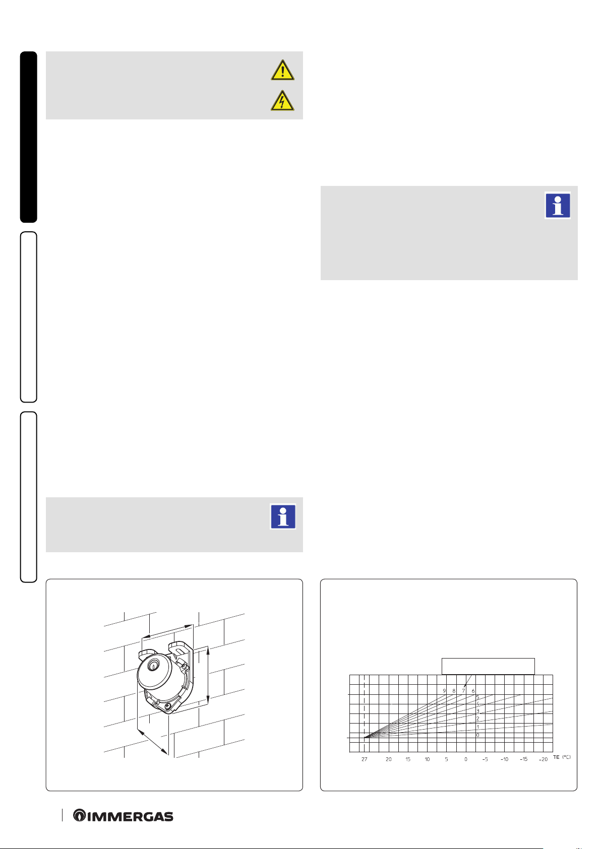
1.10 EXTERNAL TEMPERATURE PROBE OPTIONAL.
e boiler is designed for the application of the external temperature probe (Fig. 8), which is available as an optional kit. Refer to
the relative instruction sheet for positioning of the external probe.
e probe can be connected directly to the boiler electrical system
and allows the max. system ow temperature to be automatically
decreased when the external temperature increases, in order to
adjust the heat supplied to the system according to the change in
external temperature. e external probe always operates when
connected, regardless of the presence or type of room chronothermostat used and can work in combination with Immergas
chrono-thermostats. e correlation between system ow temperature and external temperature is determined by the position of
the central heating selector switch on the boiler control panel (or
on the CARV2 control panel if connected to the boiler) according to
the curves shown in the diagram (Fig. 9). e electric connection
of the external probe must be made on clamps 38 and 39 on the
terminal board in the boiler control panel (Fig. 36).
MAINTENANCE TECHNICIAN
14
14
31
45
58
EXTERNAL PROBE
Correction law of the ow temperature depending on the external
temperature and user adjustment of the central heating temperature.
Position of the central heating user
TM (°C)
MAX.
MIN
8
adjustment
9
Page 15
1.11 IMMERGAS FLUE SYSTEMS.
Immergas supplies various solutions separately from the boilers
regarding the installation of air intake terminals and ue exhaust,
which are fundamental for boiler operation.
ATTENTION:
the boiler must be installed exclusively with an original Immergas “Green
Range” inspectionable air intake system and
ue gas extraction system made of plastic,
with the exception of the C6 conguration, as
required by the regulations in force and by the
product’s approval.
is ue can be identied by an identication
rk and special distinctive marking bearing
ma
the note "only for condensation boilers".
e plastic pipes cannot be installed outdoors,
f
or tracts longer than 40 cm, without suitable
protection from UV rays and other atmospheric agents.
• Resistance factors and equivalent lengths.
Each ue component has a Resistance Factor based on experi-
mental tests and specied in the table below. e Resistance
Factor for individual components is independent from the type
of boiler on which it is installed and has a dimensionless size. It
is however, conditioned by the temperature of the uids that pass
through the pipe and therefore, varies according to applications
for air intake or ue exhaust. Each single component has a resist-
ance corresponding to a certain length in metres of pipe of the
same diameter; the so-called equivalent length, can be obtained
from the ratio between the relative Resistance Factors.
All boilers have an experimentally obtainable maximum Resist-
ance Factor equal to 100.
e maximum Resistance Factor allowed corresponds to the
resistance encountered with the maximum allowed pipe length
for each type of Terminal Kit. is information allows calculations to be made to verify the possibility of setting up various
ue congurations.
Note: to dimension the ue duc
nents, refer to the table of combustion parameters (Paragraph 4.2).
ting using commercial compo-
(A)
(B)
• Positioning the gaskets (black) for “green range” ue systems.
Position the gasket correctly (for bends and extensions) (Fig. 10):
- gasket (A) with notches, to use for bends;
- gasket (B) without notches, to use for extensions.
N.B.: if necessary, to ease the push-tting, spread the elements
with commonly-used talc.
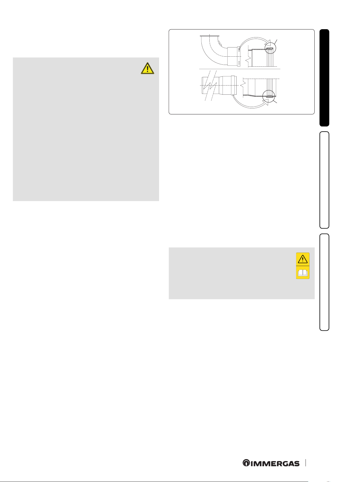
• Extension pipes and concentric elbows push-ttings.
To install push-tting extensions with other elements of the ue
extraction elements assembly, proceed as follows: Install the concentric pipe or elbow with the male side (smooth) on the female
side (with lip seal) to the end stop on the previously installed
element in order to ensure sealing eciency of the coupling.
N.B.: if the exhaust terminal and/or extension concentric pipe
needs shortening, consider that the internal duct must always
protrude by 5 mm with respect to the external duct.
N.B.: for safety purposes, do not obstruct the boiler intake/
exhaust terminal, even temporarily.
e various parts of the ue system must be checked
to ensure that they have been laid in such a way as
to prevent the coupled parts from detaching, in particular, the ue exhaust duct in the Ø80 separator kit
conguration. Should the aforesaid condition not be
adequately guaranteed, it will be necessary to use the
special clamp ring nut clip kit.
N.B.: when installing horizontal pipes, a minimum inclination
of 3% towards the boiler must be maintained, and a section clip
with pin must be installed every 3 metres.
10
INSTALLER
USER
MAINTENANCE TECHNICIAN
15
15
Page 16

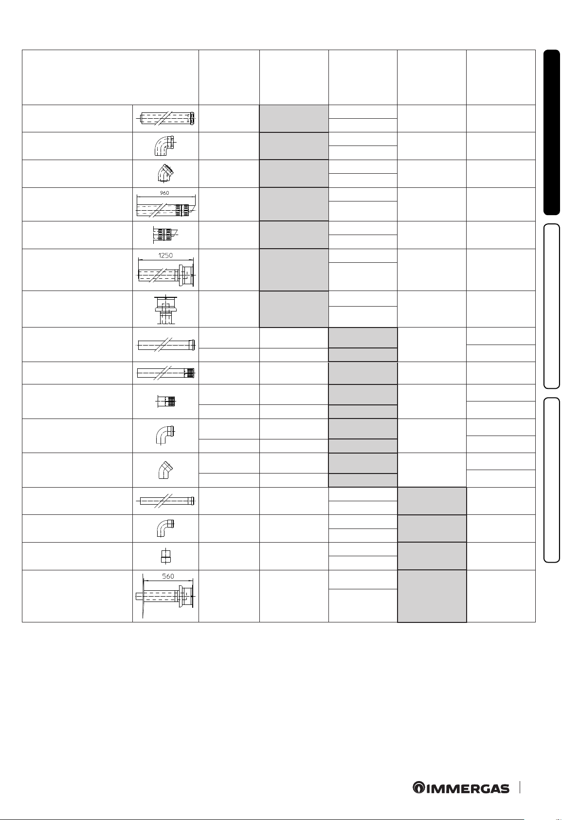
1.12 TABLES OF RESISTANCE FACTORS AND EQUIVALENT LENGTHS OF “GREEN RANGE” FLUE SYSTEM
COMPONENTS.
TYPE OF DUCT
Concentric pipe 80/125 Ø m 1
90° concentric bend Ø 80/125
INSTALLER
Concentric bend 45° Ø 80/125
Terminal complete with concentric horizontal intake-exhaust
Ø 80/125
Terminal complete with concentric vertical intake-exhaust
Ø 80/125
90° concentric bend Ø 80/125 with inspection
USER
Stub pipe with inspection Ø 80/125
Resistance
Factor
(R)
2.1 1
3.0 1.4
2.1 1
2.8 1.3
3.6 1.7
3.4 1.6
3.4 1.6
in m of concentric pipe
Length
Ø 80/125
MAINTENANCE TECHNICIAN
1616
Page 17
TYPE OF DUCT
Resistance
Factor
(R)
Length
in m of concen-
tric pipe Ø 60/100
Length
in metres
of a Ø 80 pipe
Length
in metres
of a Ø 60 pipe
Length
in m of concen-
tric pipe Ø 80/125
Concentric pipe Ø 60/100
m 1
90° concentric bend Ø 60/100
Concentric bend 45° Ø
60/100
Terminal complete with
concentric horizontal intakeexhaust Ø 60/100
Concentric horizontal intakeexhaust terminal Ø 60/100
Terminal complete with
concentric vertical intakeexhaust Ø 60/100
Concentric vertical intakeexhaust terminal Ø 60/100
Pipe Ø 80 m 1
Complete intake terminal Ø
80 m 1
Intake terminal Ø 80
Exhaust terminal Ø 80
Bend 90° Ø 80
Bend 45° Ø 80
Pipe Ø 60 m 1 for ducting Exhaust 3.3 m 0.5
Bend 90° Ø 60 for ducting
Reduction Ø 80/60
Intake and
Exhaust 6.4
Intake and
Exhaust 8.2
Intake and
Exhaust 6.4
Intake and
Exhaust 15
Intake and
Exhaust 10
Intake and
Exhaust 16.3
Intake and
Exhaust 9
Intake 0.87 m 0.1 Intake m 1.0
Exhaust 1.2 m 0.2 Exhaust m 1.0
Intake 3 m 0.5 Intake m 3.4 Exhaust m 0.9 1.4 m
Intake 2.2 m 0.35 Intake m 2.5
Exhaust 1.9 m 0.3 Exhaust m 1.6
Intake 1.9 m 0.3 Intake m 2.2
Exhaust 2.6 m 0.4 Exhaust m 2.1
Intake 1.2 m 0.2 Intake m 1.4
Exhaust 1.6 m 0.25 Exhaust m 1.3
Exhaust 3.5 m 0.55
Intake and
Exhaust 2.6
m 1
m 1.3
m 1
m 2.3
m 1.5
m 2.5
1.4 m
m 0.4
Intake m 7.3
Exhaust m 5.3
Intake m 9.4
Exhaust m 6.8
Intake m 7.3
Exhaust m 5.3
Intake m 17.2
Exhaust m 12.5
Intake m 11.5
Exhaust m 8.3
Intake m 18.7
Exhaust m 13.6
Intake m 10.3
Exhaust m 7.5
Intake 3.8
Exhaust 2.7
Intake 4.0
Exhaust 2.9
Intake m 3.0
Exhaust m 2.1
Exhaust m 1.9 m 3.0
Exhaust m 2.5 m 3.9
Exhaust m 1.9 m 3.0
Exhaust m 4.5 m 7.1
Exhaust m 3.0 4.7 m
Exhaust m 4.9 m 7.7
Exhaust m 2.7 m 4.3
m 0.4
Exhaust m 0.4
m 0.5
m 1
Exhaust m 0.6
m 0.9
m 0.9
Exhaust m 0.8
m 1.2
m 0.5
Exhaust m 0.5
0.7
Exhaust m 1.0 m 1.5
Exhaust m 1.1 m 1.6
Exhaust m 0.8 m 1.2
INSTALLER
USER
MAINTENANCE TECHNICIAN
Terminal complete with
exhaust
vertical Ø 60 for ducting
Exhaust 12.2 m 1.9
Intake m 14
Exhaust m 3.7 m 5.8
Exhaust m 10.1
1717
Page 18

1.13 OUTDOOR INSTALLATION IN PARTIALLY
PROTECTED AREA.
A partially protected location is a place where the
appliance is not exposed to the direct eects of the
weather (rain, snow, hail, etc.).
If the appliance is installed in a place where the ambient temperature drops below 0°C, use the optional
antifreeze kit, checking the ambient operating tem-
INSTALLER
perature range shown in the technical data table in
this instruction booklet.
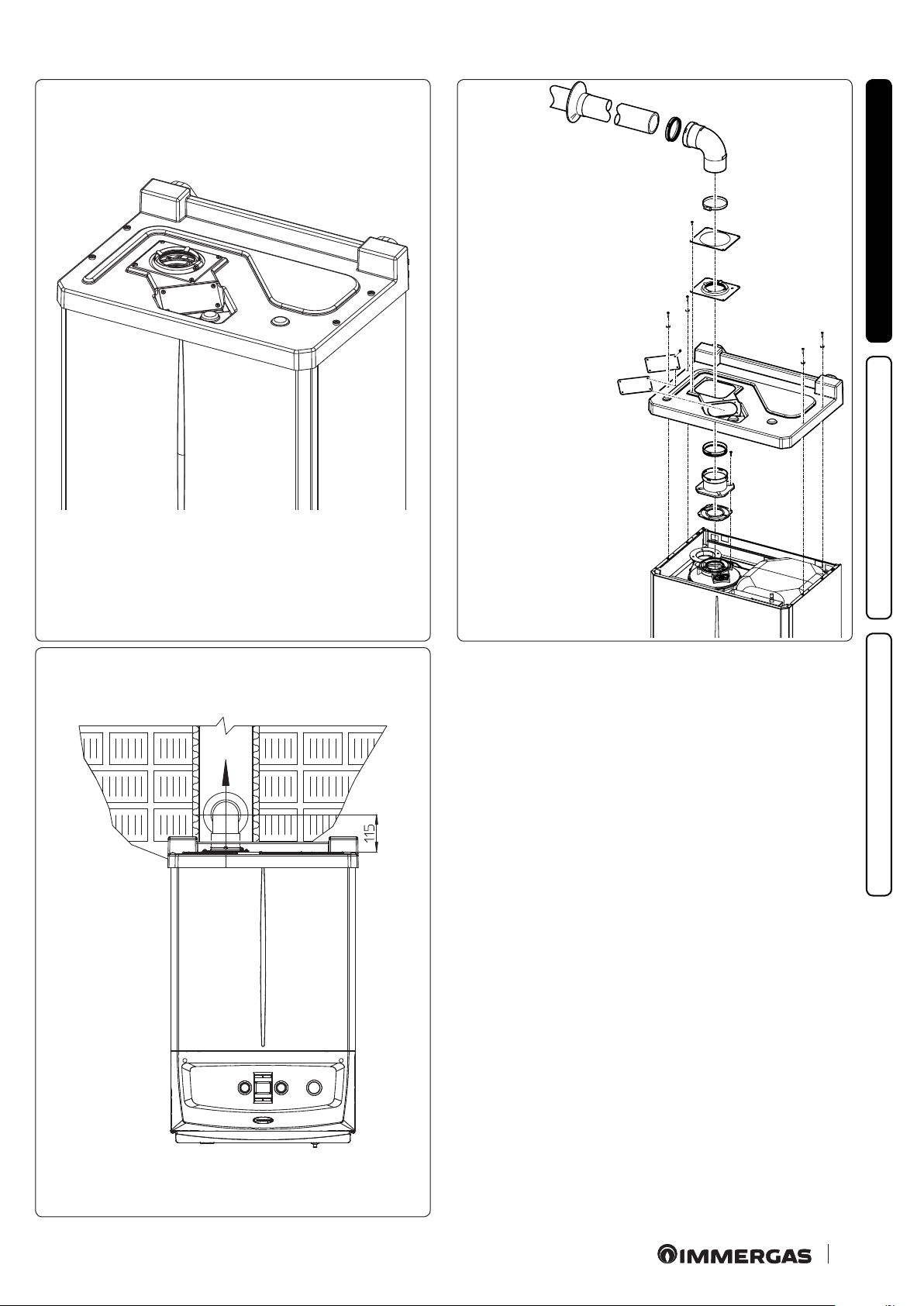
Configuration type B, open chamber and fan assisted.
(B23 or B53).
Using the special coverage kit one can achieve direct air intake
(Fig. 11) and ue gas exhaust in a single chimney or directly
outside. In this conguration it is possible to install the boiler
in a partially protected place. In this conguration the boiler is
classied as type B.
With this conguration:
- air intake takes place directly from the environment in which
the appliance is installed (external);
USER
- the ue gas exhaust must be connected to its own single chimney
(B23) or ducted directly outside via a vertical terminal for direct
exhaust (B53) or via an Immergas ducting system (B53).
e technical regulations in force must be respected.
K
it assembly (Fig. 12).
By leaving the side plugs tted it is possible to install the appliance
externally without the cover kit. Installation takes place using the
Ø60/100 and Ø 80/125 concentric intake/ exhaust kits. Refer to
the paragraph on indoor installation. In this conguration the upper cover kit guarantees additional protection for the boiler. It is
recommended but not compulsory. e Ø 80/80 separating device
cannot be used in this conguration (coupled with the cover kit).
Max. length of exhaust duct.
e ue pipe (both vertical or horizontal) can be extended to a
max. length of 30 linear metres.
Coupling of extension pipes.
To install push-tting extensions with other elements of the ue,
proceed as follows: Couple the pipe or elbow with the male side
(smooth) in the female side (with lip seal) to the end stop on the
previously installed element. is will ensure sealing eciency
of the coupling.
Conguration without cover kit in a partially protected location
(type C boiler).
By leaving the side plugs tted it is possible to install the appliance
externally without the cover kit. Installation takes place using the
Ø60/100 and Ø 80/125 concentric intake/ exhaust kits. Refer to
the paragraph on indoor installation. In this conguration the upper cover kit guarantees additional protection for the boiler. It is
recommended but not compulsory. e Ø 80/80 separating device
cannot be used in this conguration (coupled with the cover kit).
MAINTENANCE TECHNICIAN
1818
Page 19
11
12
e cover kit includes:
N° 1 ermoformed cover
N°1 Gasket clamping plate
N°1 Gasket
N°1 Gasket tightening clip
N°1 Intake hole covering plate
INSTALLER
e terminal kit includes:
N° 1 Gasket
N° 1 Exhaust ange Ø 80
N° 1 Bend 90° Ø 80
N° 1 Exhaust pipe Ø 80
N° 1 Wall sealing plate
USER
13
MAINTENANCE TECHNICIAN
19
19
Page 20
1.14 CONCENTRIC HORIZONTAL KIT INSTALLATION.
• Type C conguration, sealed chamber and fan assisted.
e position of the terminal (in terms of distances from openings,
overlooking buildings, oor, etc.) must be in compliance with the
regulations in force.
is terminal is connected directly to the outside of the building for air intake and ue gas exh
aust. e horizontal kit can
be installed with the rear, right side, le side or front outlet. For
installation with frontal outlet, one must use the xing plate and
INSTALLER
a concentric bend coupling in order to ensure sucient space to
carry out the tests required by law upon commissioning.
• External grid.
Both the Ø 60/100 and Ø 80/125 intake/exhaust terminal, if
properly installed, is pleasant to look at on the outside of the
building. Make sure that the external silicone wall sealing plate
is properly inserted in the wall.
ATTENTION:
for correct functioning of the system
the terminal with grid must be installed correctly ensuring that, the "high"
USER
indication present on the terminal is respected on installation.
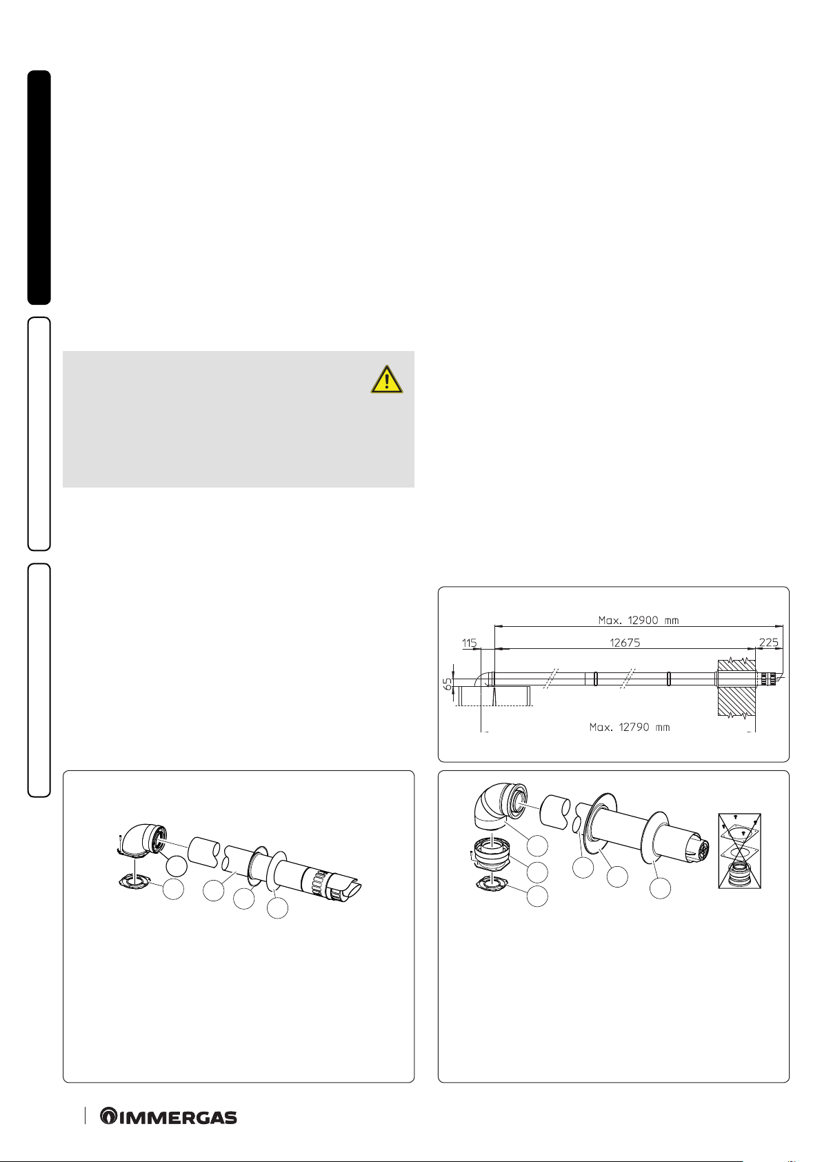
• Extensions for Ø 60/100 horizontal kit (Fig. 15).
e kit with this conguration can be extended up to a max.
horizontal length of 12.9 m including the terminal with grid and
excluding the concentric bend leaving the boiler. is conguration corresponds to a resistance factor of 100. In this case the
special extensions must be requested.
Immergas also provides a Ø 60/100 simplied terminal, which in
combination with its extension kits allows you to reach a maximum extension of 11.9 metres.
Horizontal intake-exhaust kit Ø 80/125. Kit Assembly
(Fig. 16):
to install the kit Ø 80/125 one must use the an
ged adapter kit
in order to install the ue system Ø 80/125. Install the anged
adaptor (2) on the central hole of the boiler, positioning gasket
(1) with the circular projections downwards in contact with the
boiler ange, and tighten using the screws contained in the kit.
Engage the bend (3) with the male side (smooth) to the end stop
on the adapter (1). Fit the Ø 80/125 (5) concentric terminal pipe
with the male side (smooth) to the female side of the bend (4)
(with lip seals) up to the end stop; making sure that the internal
(6) and external wall sealing plate (7) have been tted, this will
ensure sealing and joining of the elements making up the kit.
Horizontal intake-exhaust kit Ø 60/100. Kit Assembly
(Fig. 14):
install the bend with ange (2) on the central hole of the boiler,
positioning gasket (1) with the circular projections downwards in
contact with the boiler ange, and tighten using the screws present
in the kit. Fit the Ø 60/100 (3) concentric terminal pipe with the
male side (smooth) to the female side of the bend (2) up to the
end stop; making sure that the internal and external wall sealing
plate have been tted, this will ensure sealing and joining of the
elements making up the kit.
MAINTENANCE TECHNICIAN
2
1
3
4
5
C
13
15
C
13
3
2
1
e adaptor kit includes:
N° 1 - Gasket (1)
N° 1 - Adapter Ø 80/125 (2)
4
5
6
C
13
e kit includes:
N° 1 - Gasket (1)
N° 1 - Concentric bend Ø 60/100 (2)
N° 1 - Int./exhaust concentric terminal Ø 60/100 (3)
N° 1 - Internal wall sealing plate (4)
N° 1 - External wall sealing plate (5)
20
20
14
e Kit Ø 80/125 includes:
N° 1 - Concentric bend Ø 80/125 at 87° (3)
N° 1 - Concentric intake-exhaust terminal Ø 80/125 (4)
N° 1 - Internal wall sealing plate (5)
N° 1 - External wall sealing plate (6)
e remaining kit components must not be used
16
Page 21
C
13
17
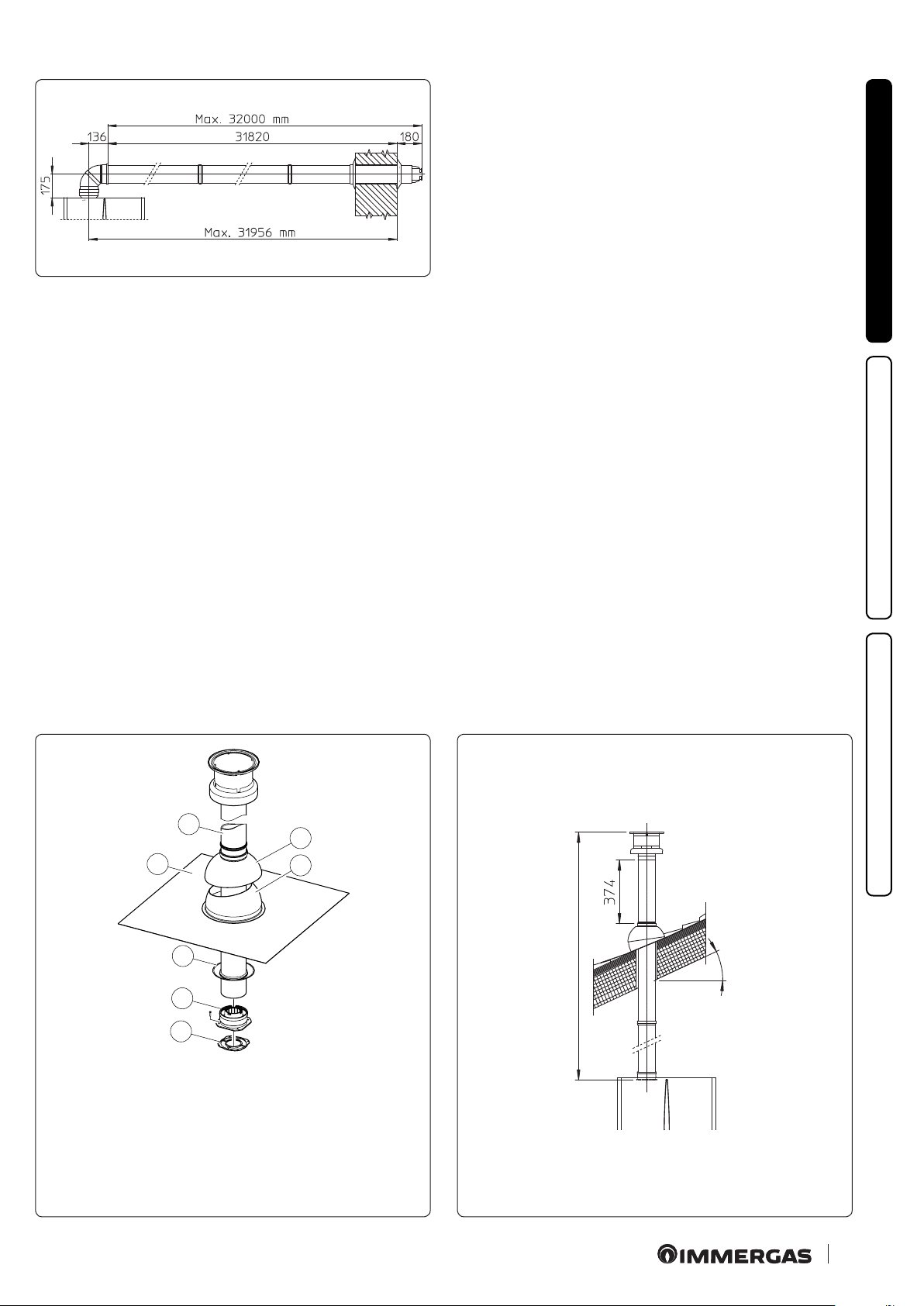
• Extensions for Ø 80/125 horizontal kit (Fig. 17).
e kit with this conguration can be extended up to a max.
length of 32 m, including the terminal with grid and excluding
the concentric bend leaving the boiler. If additional components
are assembled, the length equivalent to the maximum allowed
must be subtracted. In this case the special extensions must be
requested.
1.15 CONCENTRIC VERTICAL KIT INSTALLATION.
• Type C conguration, sealed chamber and fan assisted.
Concentric vertical intake and exhaust kit. is vertical terminal
is connected directly to the outside of the building for air intake
and ue gas exhaust.
N.B.: the vertical kit with aluminium tile enables installation on terraces
and roofs with a maximum slope of 45% (approx 25°) and the height
between the terminal cap and half-shell (374 mm for Ø 60/100 and 260
mm for Ø 80/125) must always be observed.
Vertical kit with aluminium tile Ø 60/100.
Kit assembly (Fig. 18):
install the concentric ange (2) on the central hole of the boiler,
positioning gasket (1) with the circular projections downwards
in contact with the boiler ange, and tighten using the screws
contained in the kit.
Installation of the fake aluminium tile: replace the tiles with the
aluminium sheet (4), shaping it to ensure that rainwater runs o.
Position the xed half-shell (6) on the aluminium tile and insert
the intake-exhaust pipe (5). Fit the Ø 60/100 concentric terminal
pipe with the male side (5) (smooth) into the ange (2) up to the
end stop; making sure that the wall sealing plate has been tted
(3), this will ensure sealing and joining of the elements making
up the kit.
NOTE: when the boiler is installed in areas where very cold temperatures can be reached, a special anti-freeze kit is available that
can be installed as an alternative to the standard kit.
• Extensions for vertical kit Ø 60/100 (Fig. 19).
e kit with this conguration can be extended to a max. straight
vertical length of 14.4 m, including the terminal. is conguration corresponds to a resistance factor of 100. In this case specic
extensions must be requested.
INSTALLER
USER
5
4
3
2
1
e Kit includes:
N° 1 - Gasket (1)
N° 1 - Female concentric ange (2)
N° 1 - Wall sealing plate (3)
N° 1 - Aluminium tile (4)
N° 1 - Int./exhaust concentric pipe Ø 60/100 (5)
N° 1 - Fixed half-shell (6)
N° 1 - Mobile half-shell (7)
7
6
C
33
C
33
MAINTENANCE TECHNICIAN
Max. 45%
MAX. LENGTH 14400 mm)
18
19
21
21
Page 22

Vertical kit with aluminium tile Ø 80/125.
Kit assembly (Fig. 20):
to install the kit Ø 80/125 one must use the an
ged adapter kit
in order to install the ue system Ø 80/125. Install the anged
adaptor (2) on the central hole of the boiler, positioning gasket
(1) with the circular projections downwards in contact with the
boiler ange, and tighten using the screws contained in the kit.
Installation of the fake aluminium tile: replace the tiles with the
aluminium sheet (4), shaping it to ensure that rainwater runs o.
Position the xed half-shell (5) on the aluminium tile and insert
INSTALLER
the intake-exhaust pipe (7). Fit the Ø 80/125 concentric terminal
pipe with the male side (smooth) to the female side of the adapter
(1) (with lip gaskets) up to the end stop; making sure that the wall
sealing plate (3) has been tted, this will ensure sealing and joining
of the elements making up the kit.
7
USER
e adaptor kit includes:
N° 1 - Gasket (1)
N° 1 - Adapter
Ø 80/125 (2)
6
5
4
3
2
1
• Extensions for vertical kit Ø 80/125 (Fig. 21).
e kit with this conguration can be extended up to a max.
length of 32 m including the terminal. If additional components
are assembled, the length equivalent to the maximum allowed
must be subtracted. In this case specic extensions must be
requested.
1.16 SEPARATOR KIT INSTALLATION.
Type C conguration, sealed chamber and fan assisted.
• Separator kit Ø 80/80.
is kit allows air to come in from outside the building and the
exhaust to exit from the chimney, ue or intubated duct through
divided ue exhaust and air intake pipes. Combustion products
are expelled from pipe (S) (in plastic, so as to resist acid condensate). Air is taken in through duct (A) for combustion (this
is also in plastic). e intake pipe (A) can be installed either on
C
33
the right or le hand side of the central exhaust pipe (S). Both
ducts can be routed in any direction.
• Kit assembly (Fig. 22):
install ange (4) on the central hole of the boiler, positioning
gasket (1) with the circular projections downwards in contact
with the boiler ange, and tighten using the hex screws with
at tip contained in the kit. Remove the at ange present in
the lateral hole with respect to the central one (according to
needs) and replace it with the ange (3), positioning the gasket
(2) already present in the boiler and tighten using the supplied
self-threading screws. Fit the male side (smooth) to the bends (5)
in the female side of the anges (3 and 4). Fit the intake terminal
(6) with the male side (smooth) in the female side of the bend
(5) up to the end stop, ensuring that the internal and external
wall sealing plates are tted. Fit the exhaust pipe (9) with the
male end (smooth) to the female end of the bend (5) up to the
e Kit Ø 80/125 includes:
N° 1 - Wall sealing plate (3)
N° 1 - Aluminium tile (4)
N° 1 - Fixed half-shell (5)
N° 1 - Mobile half-shell (6)
N° 1 - Concentric intake-exhaust terminal Ø 80/125 (7)
e remaining kit components must not be used
MAINTENANCE TECHNICIAN
Max. 32000 mm
Max. 45%
C53* - C
5
5
7
20
C
33
e kit includes:
N° 1 - Exhaust gasket (1)
N° 1 - Flange gasket (2)
N° 1 - Female intake ange (3)
N° 1 - Female exhaust ange (4)
N° 2 - Bend 90° Ø 80 (5)
N° 1 - Intake terminal Ø 80 (6)
N° 2 - Internal wall sealing plates (7)
N° 1 - External wall sealing plate (8)
N° 1 - Exhaust pipe Ø 80 (9)
* to complete C53 conguration, also provide for a “green
e conguration on walls opposite the building is not allowed.
S
9
4
1
range” roof discharge terminal.
6
3
2
7
A
83
8
22
22
21
22
Page 23

end stop; making sure that the internal wall sealing plate has
been tted, this will ensure sealing and joining of the elements
making up the kit.
• Installation clearances (Fig. 23).
e minimum installation clearance measurements of the Ø
80/80 separator terminal kit have been stated in some limit
conditions.
• Extensions for separator kit Ø 80/80.
e maximum vertical straight length (without bends) that
can be used for Ø 80 intake and exhaust pipes is 41 metres, regardless from whether they are used for intake or exhaust. e
maximum horizontal straight length (with bend in suction and
in exhaust) that can be used for Ø 80 intake and exhaust pipes
is 36 metres, regardless from whether they are used for intake
or exhaust. Please note the type of installation C
must be done
43
with a natural draught ue.
N.B.: to favour the removal of possible condensate forming in the
exhaust pipe, tilt the pipes towards the boiler with a minimum
slope of 1.5% (Fig. 24).
INSTALLER
USER
C
43
23
C
83
MAINTENANCE TECHNICIAN
80 mm
Minimum slope 1.5%
24
23
23
Page 24

1.17 ADAPTOR C9 KIT INSTALLATION.
is kit allows an Immergas boiler to be installed in "C93" congu-
ration, with combustion air intake directly from the sha where
the ue gas exhaust is, obtained by means of a ducting system.
System composition.
e system must be combined with the following components
(sold separately) to be functional and complete:
- kit C93 Ø 100 or Ø125 version;
- rigid ducting Ø 60 and Ø 80 and exible Ø 50 and Ø 80 kit;
INSTALLER
- ue exhaust kit Ø 60/100 or Ø 80/125 congured according to
the installation and type of boiler.
USER
A
B
Ducting
Ø 60 Rigid and
Ø 50 Flexible
(A) mm
66 106 126
SHAFT
(B) mm
A
C
SHAFT
(C) mm
Kit Assembly.
- Mount the components of kit "C9" on the door (A) of the ducting
system (Fig. 26).
- (Version Ø 125 only) mount the anged adaptor (11) interposing
the concentric gasket (10) on the boiler, tting it with the screws
(12).
- Mount the ducting system as described in the relative instructions sheet.
- Calculate the distances between the boiler drain and the bend
of the ducting system.
- Prepare the boiler ue system, making sure that the internal pipe
of the concentric kit is tted up to the end stop in the ducting
system curve (Quota "X" Fig. 27), whereas the external pipe must
reach the end stop of the adapter (1).
N.B.: to encourage the removal of possible condensate forming in the
exhaust pipe, tilt the pipes towards the boiler with a minimum slope of
1.5%.
- Mount the cover (A) complete with adaptor (1) and caps (6) on
the wall and assemble the ue system to the ducting system.
N.B.: (version Ø 125 only) before assembly check the gaskets are in the
right position. In the event component lubrication (already carried out
by the manufacturer) is not sucient, remove the residual lubricant
using a dry cloth, then to ease tting coat the parts with common or
industrial talc.
Once all components have been assembled properly, the exhaust
fumes will be expelled via the ducting system; the combustion
air for normal boiler operation will be aspirated directly by the
sha (Fig. 27).
Ducting
Ø 80 Rigid
(A) mm
86 126 146
Ducting
Ø 80 Flexible
(A) mm
90 130 150
Kit composition:
Ref. Qty Description
1 1 Door adaptor Ø 100 or Ø 125
MAINTENANCE TECHNICIAN
2 1 Door gasket made of neoprene
3 4 Screws 4.2 x 9 AF
4 1 Hex headed screw M6 x 20
5 1 Flat nylon washer M6
6 2 Door hole closure metal-sheet plate plug
7 1 Plug gasket made of neoprene
8 1 Toothed washer M6
9 1 Nut M6
10 1 (kit 80/125) Concentric gasket Ø 60-100
11 1 (kit 80/125) Flanged adapter Ø 80-125
12 4 (kit 80/125) Hex headed screws M4 x 16 slotted
- 1 (kit 80/125) Bag of lubricating talc
Supplied separately:
Ref. Qty Description
A 1 Ducting kit door
SHAFT
(B) mm
SHAFT
(B) mm
SHAFT
(C) mm
SHAFT
(C) mm
25
Installation drawings key:
Unique identication of the component
1
in the kit
Identication of the component not sup-
A
plied in this kit
12
12
11
2
1
3
A
3
9
8
3
7
6
5
4
10
6
26
24
24
Page 25

Technical data.
- e dimensions of the shas must ensure a minimum gap between the outer wall of the smoke duct and the inner wall of the
sha: 30 mm for circular section shas and 20 mm in the event
of a square section sha (Fig. 24).
- Maximum 2 changes of direction are allowed on the vertical
section of the ue system with a maximum clearance angle of
30° with respect to the vertical.
- e maximum vertical extension using a Ø 60 ducting system is
13 m, the maximum extension includes 1 bend Ø 60/10 at 90°,
1 m of horizontal pipe 60/100, 1 90° ducted bend Ø 60 and the
roof terminal for ducting.
To determine the C
ue system in congurations other than
93
that described (Fig. 26) one must consider that 1 metre of ducted
pipe according to the indications described has a resistance factor
equal to 4.9.
- e maximum vertical extension using a Ø 80 ducting system
is 28 m, the maximum extension includes 1 adapter 60/100 to
80/125, 1 87° bend Ø 80/125, 1 m of horizontal pipe 80/125, 1
90° ducted bend Ø 80 and the roof terminal for ducting.
To determine the C
ue system in congurations other than
93
that described (Fig. 26) one must consider the following head
losses:
- 1 m of concentric pipe Ø 80/125 = 1 m of ducted pipe;
- 1 87° bend = 1.4 m of ducted pipe;
Consequently one must subtract the equivalent length of the
part added to the 28 m available.
INSTALLER
USER
C
93
MAINTENANCE TECHNICIAN
X
27
25
25
Page 26

1.18 DUCTING OF FLUES OR TECHNICAL SLOTS.
Ducting is an operation through which by inserting one or
more relevant pipes, one achieves a system for the evacuation of the combustion products of a gas appliance, consisting in the combination of an existing or new ducting pipe
with a chimney, ue or technical slot (also in new buildings)
(Fig. 28). Ducting requires ducts declared to be suitable for the
purpose by the manufacturer, following the installation and user
instructions, provided by the manufacturer and the requirements
of the regulations in force.
INSTALLER
Immergas ducting system.
e Ø 60 rigid, Ø50 and Ø 80 exible and Ø80 rigid “Green Range”
ducting systems must only be used for domestic use and with Immergas condensing boilers.
In any case, ducting operations must respect the provisions
contained in the standard and in current technical regulations;
in particular, the declaration of conformity must be compiled
at the end of work and on commissioning of the ducted system.
e instructions in the project or technical report must likewise
be followed, in cases provided for by the standard and current
technical regulations. To guarantee reliability and operation over
time of the ducting system, make sure:
USER
- it is used in average atmospheric and environmental conditions,
according to current regulations (absence of combustion products, dusts or gases that can alter the normal thermophysical or
chemical conditions; existence of temperatures coming within
the standard range of daily variation, etc.).
- Installation and maintenance must be performed according to
the indications supplied by the manufacturer included with the
“green range” ducting system chosen and in compliance with
the regulations in force.
- e maximum length specied by the manufacturer must be
respected; in this regard:
- e max. possible length of the Ø 60 exible ducting vertical
section is equal to 22 m. is length is obtained considering the
complete Ø 80 exhaust terminal, 1m of Ø 80 pipe in exhaust,
two 90° Ø 80 bends at boiler outlet.
- e max. possible length of the Ø 80 exible ducting vertical
section is equal to 18 m. is length is obtained considering the
Ø80 complete exhaust terminal, 1m of Ø 80 pipe in exhaust, two
90° Ø 80 bends at boiler outlet for connecting to the ducting
system and two direction changes of the exible hose inside
the chimney/technical slot.
- e max. possible length of the Ø 80 exible ducting vertical
section is equal to 30 m. is length is obtained considering the
complete Ø 80 exhaust terminal, 1m of Ø 80 pipe in exhaust,
two 90° Ø 80 bends at boiler outlet.
You can also install an additional Ø50 exib
le ducting system
the specications of which are found on the relevant instructions
sheet inside the kit.
1.19 CONFIGURATION TYPE B, OPEN CHAMBER AND
FAN ASSISTED FOR INDOORS.
e appliance can be installed inside buildings in B23 or B53 mode;
in this case, all technical rules and national and local regulations
in force, must be complied with.
For installation the cover kit must be used, referred to in Par. 1.13.
MAINTENANCE TECHNICIAN
26
26
C
53
28
Page 27

1.20 FLUE EXHAUST TO FLUE/CHIMNEY.
Flue exhaust does not necessarily have to be connected to a branched
type traditional ue for type B appliances with natural draught (CCR).
e ue exhaust, for boiler clots installed in C conguration, can be
connected to a special LAS type multiple ue. For B23 congurations,
exhaust is only allowed into individual chimney or directly into the
external atmosphere via a suitable terminal, unless otherwise provided
for by local regulations in force. e multiple ues and the combined
ues must also only be connected to type C appliances of the same
type (condensation), having nominal heat inputs that do not dier by
more than 30% less with respect to the maximum that can be attached
and powered by the same fuel. e thermo-uid dynamic features
(ue ow rate, % of carbon dioxide, % humidity etc.) of the applianc-
es attached to the same multiple ues or combined ues, must not
dier by more than 10% with respect to the average boiler attached.
Multiple and combined ues must be specially designed according to
the calculation method and requirements of the standards (such as
UNI EN 13384), by professionally qualied technical sta. Chimney
or ue sections for connection of the ue exhaust pipe must comply
with requisites of technical standards in force. It is possible to replace
a type C conventional device with one provided with condensation
only, if the derogation conditions established by the regulations in
force have been veried.
1.21 FLUES, CHIMNEYS AND CHIMNEY CAPS.
e ues, chimneys and chimney caps for the evacuation of combustion products must be in compliance with applicable standards.
Chimneys and roof-installed exhaust terminals must comply with
the outlet height and with the distance from technical volumes
set forth by the technical standards in force.
Positioning the wall ue exhaust terminals.
e wall ue exhaust terminals must:
- be installed on external perimeter walls of the building;
- be positioned according to the minimum distances specied in
current technical standards.
Combustion products exhaust of natural draught or fan assisted
appliances in open-top closed environments.
In spaces closed on all sides with open tops (ventilation pits,
courtyards etc.), direct combustion product exhaust is allowed for
natural draught or fan assisted gas appliances with a heat input
range from 4 to 35 kW, provided the conditions as per the current
technical standards are respected.
INSTALLER
USER
272927
MAINTENANCE TECHNICIAN
Page 28

1.22 WATER TREATMENT SYSTEM FILLING.
As already mentioned in the previous paragraphs, a
treatment of the thermal and domestic system water
is required, in compliance with the local standards
in force.
e parameters that inuence the duration and proper operation of the heat exchanger are the water's PH, total
hardness, conductivity, and oxygen, together with the system's
processing residues (any welding residues), any oil present and
INSTALLER
corrosion products that can, in turn, cause damage to the heat
exchanger.
In order to prevent this from happening, you are recommended
to:
- Before installation on new systems as well as old ones, clean the
system with clean water to eliminate solid residues contained
therein
- Clean the system with a chemical treatment:
- Clean the new system with a suitable cleaning device (for
example Sentinel X300, Fernox Cleaner F3 or Jenaqua 300)
combined with thorough washing.
- Clean the old system with a suitable cleaning device (for ex-
ample Sentinel X400 or X800, Fernox Cleaner F3 or Jenaqua
USER
400) combined with thorough washing.
- Check the maximum total hardness and quantity of lling
water referring to the graphics (Fig. 30); if the contents and
hardness of the water are below the indicated curve, no specic
treatment is required; otherwise, to limit the content of calcium
carbonate, you must provide for water-lling treatment.
- Should you be required to provide for water treatment, this
should be carried out by completely desalinating the lling
water. As opposed to the complete soening process, desalinating the water completely not only removes hardening agents
(Ca, Mg), but also eliminates all other minerals to reduce
water-lling conductivity up to 10 microsiemens/cm. Given its
low conductivity, desalinated water does not only prevent the
formation of lime scale, but also serves as protection against
corrosion.
- Insert a suitable inhibitor / passivator (for example Sentinel
X100, Fernox Protector F1, or Jenaqua 100); if required, also
insert appropriate antifreeze (such as for example Sentinel
X500, Fernox Alphi 11 or Jenaqua 500).
MAINTENANCE TECHNICIAN
- Check electrical conduction of the water, which should be
higher than 2000 µs/cm in the case of treated water and lower
than 600 µs/cm in the case of non-treated water.
- To prevent corrosion, the water system's PH should be between
6.5 and 8.5.
- Check the maximum content of chlorides, which should be
less than 250 mg/l.
N.B.: for quantities and methods of use of water-treatment
products, refer to the instructions provided by their manufacturer.
System water litres
Water total hardness °F
N.B.: the graph refers to the entire life cycle of the system. erefore, also consider scheduled and unscheduled maintenance,
which involves emptying and lling the said system.
1.23 SYSTEM FILLING.
Once the boiler is connected, proceed with system lling via the
lling cock (Part. 1 Fig. 32). Filling is performed at low speed to
ensure release of air bubbles in the water via the boiler and central
heating system vents.
e boiler has a built-in automatic vent valve on the pump. Check if the
cap is loose. en open the radiator vent valves.
Close radiator vent valves when only water escapes from them.
Close the lling valve when the boiler pressure gauge indicates
approx. 1.2 bar.
N.B.: during these operations, enable the automatic vent functions on the boiler.
1.24 FILLING THE CONDENSATE DRAIN TRAP.
On rst lighting of the boiler, ue gas may come out the condensate drain; aer a few minutes’ operation check that this no longer
occurs. is means that the drain trap is lled with condensate to
the correct level preventing the passage of ue gas.
1.25 GAS SYSTEM STARTU P.
To start up the system, refer to the technical standards in force.
In particular, for new gas systems:
- open windows and doors;
- avoid presence of sparks or naked ames;
- bleed all air from pipelines;
- ensure the internal system is properly sealed according to the
specications set forth by technical regulations in force.
283028
Page 29

1.26 BOILER STARTUP IGNITION.
To commission the boiler (the operations listed below must only be
performed by qualied personnel and in the presence of sta only):
- check that the internal system is properly sealed according to
the specications set forth by regulations in force;
- ensure that the type of gas used corresponds to the boiler settings
(the type of gas appears on the display on rst electrical power supply,
or by checking the relative parameter “G”);
- check that there is no air in the gas pipe;
- check connection to a 230V-50Hz power mains, correct L-N polarity
and the earthing connection;
- check that the intake/exhaust terminals are not obstructed and
that they are installed properly;
- check that the drain trap is full and that it prevents any passage
of ue gas into the room;
- check that there are no external factors that may cause the formation
of fuel pockets;
- perform the ue test and, if needed, set the correct value of the
parameter “F0” (Par. 3.14);
- activate the quick calibration function (Par. 3.13);
- switch the boiler on and ensure correct ignition;
- make sure that the gas ow rate and relevant pressure values
comply with those given in the manual (Par. 4.1);
- ensure that the safety device intervenes in the event of gas supply
failure and check the relative intervention time;
- check the intervention of the main switch located upstream from
the boiler and in the boiler.
e system must not be started up if even only one of the checks
s
hould be negative.
INSTALLER
USER
2929
MAINTENANCE TECHNICIAN
Page 30

1.27 CIRCULATION PUMP.
During central heating mode, the Auto and Fixed operating modes
are available.
• Auto (A5 = 0): automatic circulator pump speed and proportion-
al head: e automatic circulator pump speed varies according
to the power emitted by the burner; the greater the power, the
greater the speed. Moreover, within the parameter, one can
also adjust the circulator pump operating range by setting the
maximum speed “A3” parameter (adjustable from 6 to 9) and
INSTALLER
the “A4” minimum speed parameter (adjustable from 6 to the
max. set speed).
• ∆T Constant (A5 = 5 ÷ 25 K): the pump speed varies to maintain
the ∆T constant between the system ow and return according
to set value K (A5 = 15 Default).
• Fixed (6 ÷ 9): by setting parameters “A3” and “A4” at the same
value, the pump operates at constant speed.
N.B.: for the boiler to work properly, it is not allowed to drop
below the minimum value indicated above.
In domestic hot water mode, the circulator pump always runs at
full speed.
USER
Pump release. If aer a long period of inactivity, the circulator
is blocked, adjust the screw in the centre of the head in order
to manually release the motor sha. Take great care during this
operation to avoid damage to the motor.
By-pass Regulation (Part. 3 Fig.32).
e boiler leaves the factory with the bypass open.
I
f necessary, the bypass can be regulated to system requirements
from minimum (bypass closed) to maximum (bypass open). Adjust using a at-head screwdriver. Turning clockwise opens the
bypass and anticlockwise closes it.
Total head available to the system.
MAINTENANCE TECHNICIAN
Head (kPa)
C
Speed 9
A
Speed 9
D
Speed 6
B
Circulator pump absorbed power (W)
30
30
Flow rate (l/h)
A+B = Head available with bypass closed
B = Head available with bypass open
C+D = Power absorbed by the pump with bypass closed (dotted area)
D = Power absorbed by the pump with bypass open (dotted area)
31
Page 31

1.28 KITS AVAILABLE ON REQUEST.
• System cut-o valve kits with or without inspectionable lter
(on request). e boiler is designed for installation of system
interception cocks to be placed on ow and return pipes of the
connection assembly. is kit is very useful for maintenance
because it allows to empty just the boiler without having to empty
the entire system. Moreover, the version with lter preserves the
functioning characteristics of the boiler thanks to its inspectionable lter.
• System zone control unit kit (on request). If the central heating
system is to be divided into several zones (max. three), in order
to interlock them with separate adjustments and to keep water
ow rate high for each zone, Immergas supplies zone system kits
by request.
• Polyphosphate dispenser kit (on request). e polyphosphate
dispenser reduces the formation of lime-scale and preserves the
original heat exchange and domestic hot water production conditions. e boiler is prepared for application of the polyphosphate
dispenser kit.
N.B.: this is a type of chemical conditioning treatment for do-
mestic hot water, if provided for by current regulations.
• Relay board (on request). e boiler is prepared for the instal-
lation of a relay board that allows to increase the features of the
appliance and therefore functioning possibilities.
• Cover kit (on request). If installed outdoors in a partially protected place with direct air intake, it is compulsory to mount the
appropriate top protective cover for the correct functioning of
the boiler and to protect it from adverse weather conditions.
• Cycloidal lter kit (on request). e magnetic cycloidal lter is
able to detect the ferrous residues present in the system's water.
anks to the two cocks in the kit, it facilitates maintenance by
cleaning the lter without having to empty the circuit.
e above-mentioned kits are supplied complete with instructions
f
or assembly and use.
INSTALLER
USER
3131
MAINTENANCE TECHNICIAN
Page 32

1.29 BOILER COMPONENTS.
INSTALLER
USER
MAINTENANCE TECHNICIAN
Key:
1 - Filling valve system
2 - Draining valve system
3 - Bypass
4 - 3-way valve (motorised)
5 - 3 bar safety valve
6 - Gas valve
7 - Boiler pump
8 - Air intake pipe
9 - Flow probe
10 - Return probe
323232
11 - Air / gas manifold
12 - Flue probe
13 - Flue gas sample points
(air A) - (ue gas F)
14 - Domestic hot water
expansion vessel
15 - System expansion vessel
16 - Condensation module
17 - Burner
18 - Ignition/detection
electrodes
19 - Fan
20 - Air / gas mixer
21 - Gas nozzle
22 - D.H.W. probe
23 - Air vent valve
24 - Stainless steel storage tank
25 - System pressure switch
26 - Condensate drain trap
27 - Control panel
28 - 8 bar safety valve
29 - Storage tank draining tting
Page 33

INSTRUCTIONS FOR USE AND
2
MAINTENANCE.
2.1 GENERAL WARNINGS.
ATTENTION:
• Never expose the wall-mounted boiler
to direct vapours from a cooking surface.
• e device can be used by children at least 8
years old as well as by persons with reduced
physical, sensory or mental capabilities, or
lack of experience or required knowledge,
provided that they are under surveillance,
or aer they have been instructed relating
to the safe use and have understood the potential dangers. Children must not play with
the appliance. Cleaning and maintenance
destined to be performed by the user can not
be carried out by unsupervised children.
• For safety purposes, check that the air intake/ue exhaust terminals (if
tted) are not
blocked.
• If temporary shutdown of the boiler is required, proceed as follows:
a) drain the heating system if antifreeze is
not used;
b) shut-o all electrical, water and gas sup-
plies.
• In the case of work or maintenance to
structures located in the vicinity of ducting
or devices for ue extraction and relative
accessories, switch off the appliance and
on completion of operations ensure that a
qualied technician checks eciency of the
ducting or other devices.
• Never clean the appliance or connected parts
with easily ammable substances.
• Do not open or tamper with the appli-
ance.
• Do not take apart or tamper with the
intake and exhaust pipes.
• Only use the user interface devices listed in
this section of the booklet.
• Do not climb on the appliance, do not use
the appliance as a supporting surface.
ATTENTION:
e use of components involving use of
electrical power requires some fundamental rules to be observed such as:
- do not touch the appliance with wet or moist
parts of the body; do not touch when barefoot;
- never pull electrical cables or leave the appliance exposed to atmospheric agents (rain,
sunlight, etc.);
- if the power cable is damaged, it must be
replaced by a cable or special assembly by
contacting a qualied company (e.g. the Immergas Authorised Aer-Sales Technical Assistance Service) for its replacement to avoid
a hazard.
- if the appliance is not to be used for a certain
period, disconnect the main power switch.
ATTENTION:
water at a temperature of more than 50
°C can cause serious burns. Always check
the water temperature before any use.
INSTALLERUSER
MAINTENANCE TECHNICIAN
• Never leave containers or ammable sub-
stances in the same environment as the appliance.
e temperatures indicated by the display have a tolerance of +/- 3°C due to environmental conditions that
cannot be blamed on the boiler.
3333
Page 34

A
TTENTION:
if you smell gas in the building:
- close the gas meter interception device
or the main interception device;
- if possible, close the gas interception cock on
the product;
- if possible, open doors and windows wide and
INSTALLERUSER
create an air current;
ATTENTION:
if you smell burning or see smoke
coming out of the appliance, switch it
o, disconnect the power, close the main gas
cock, open the windows and call an authorised
company (e.g. Authorised Aer-Sales Service).
- do not use open ames (e.g. lighters, matches);
- do not smoke;
- do not use electrical switches, plugs, door
bells, telephones or intercom devices in the
building;
- call an authorised company (e.g. Authorised
Aer-Sales Service).
ATTENTION:
At the end of its service life, the appliance must not be disposed of like normal household waste nor abandoned
in the environment, but must be removed by a
professionally authorised company as required
by current legislation. Contact the manufacturer for disposal instructions.
MAINTENANCE TECHNICIAN
3434
Page 35

2.2 CLEANING AND MAINTENANCE.
To preserve the boiler's integrity and keep the safety
features, performance and reliability, which distinguish it, unchanged over time, you must execute
maintenance operations on a yearly basis in compliance with what is stated in the relative point at
“annual check and maintenance of the appliance”, in
compliance with national, regional, or local standards in force.
Annual maintenance is essential to validate the conventional
warranty of Immergas.
INSTALLERUSER
2.3 CONTROL PANEL.
Key:
1 - Domestic hot water temperature
selector
2 - Reset Button
3 - Summer/Winter Button
4 - Central heating temperature selector
5 - Information buttons
6 - O/Stand-by/On Button
7 - Boiler manometer
8 - DHW production phase function ac-
tive
9 - Blocked boiler, it needs to be un-
blocked by pressing the “RESET”
button
10 - Flame presence symbol and relative
output scale
11 - Operation in summer mode
12 - Operation in winter mode
13 - Room central heating mode function-
ing active
MAINTENANCE TECHNICIAN
14 - Temperature indicator, boiler info and
error codes
15 - Boiler in Stand-by mode
16 - Presence of external connected devices
17 - Not used on this model
18 - Operation with external temperature
probe active (optional)
19 - Boiler connected to remote control V2
(optional)
20 - Not used on this model
353335
Page 36

2.4 USING THE BOILER.
Before ignition make sure the heating system is lled with water
and that the manometer (7) indicates a pressure of 1 ÷ 1.2 bar.
- Open the gas cock upstream from the boiler.
- Press the button ( ) until the display switches on. At this point,
the boiler goes to the state previous to switch-o.
- If the boiler is on “Stand-by”, press ( ) again to enable it, otherwise go to the next point.
- en press the button ( ) in sequence and set the boiler in
INSTALLERUSER
the summer (
• Summer ( ): in this mode the boiler only works to produce
DHW; the temperature is set via the selector (1) and the relative
temperature is shown on the display via the indicator (14).
• Winter ( ): in this mode the boiler works both for producing
domestic hot water and for central heating. e temperature of
the DHW is always regulated via the selector (1), the heating
temperature is regulated via selector (4) and the relative temperature is shown on the display via the indicator (14).
From this moment the boiler functions automatically. With no
demand for heat (central heating or domestic hot water production) the boiler goes to “standby” function, equivalent to the boiler
being powered without presence of am
ignites, the relative symbol (
• Operation with Comando Amico Remoto remote control V2
V2
(CAR
symbol will appear on the display. e boiler regulation parameters can be set via the CARV2 control panel and the
button remains active on the boiler control panel, along with
(
functioning state is shown.
Caution: if the boiler is switched “o ” the CARV2 will display
the connection error symbol “ERR>CM”, the CARV2 is however
powered constantly so as not to lose the stored programs.
• Operation with optional external probe ( ). In the case of a
system with optional external probe, the boiler ow temperature
for room central heating is managed by the external probe depending on the external temperature measured (Par. 1.10). e
ow temperature can be modied by selecting the functioning
curve via the selector switch (4) (or on the CARV2 control panel,
if connected to the boiler) selecting a value from “0 to 9”.
MAINTENANCE TECHNICIAN
With external probe present, the relative symbol ( ) will
appear on the display. In the central heating mode, if the temperature of the water contained in the system is sucient to heat
the radiators, the boiler can only function with the activation of
the pump.
• Standby mode. Press button (6) until the ( ) symbol appears.
e boiler remains active from this moment and the anti-freeze
function, pump anti-block function and 3-way and signalling of
any anomalies is guaranteed.
) (Optional). If the CARV2 is connected, the ( )
) for switch-o (“o ” mode only) and the display where the
) or winter ( ) position.
e. Each time the burner
) is displayed.
“O” mode. By holding the button ( ) down for 8 seconds,
only the central point remains lit on the display, and all boiler
functions are disabled. e safety functions are not guaranteed
in this mode.
ATTENTION:
in “Stand-by” and “Off” mode, the
boiler is still powered.
• “Automatic vent” mode. When the function is enabled, every
time the boiler is electrically powered, the system automatic
vent function is activated (lasting 8 minutes). is function is
displayed via a countdown signalled by the indicator (14). During
this period the DHW and CH functions are not active.
e “automatic vent” function can be annulled by pressing the
“ ” button.
• Display operation. e display lights up while the control
panel is being used; aer a set inactivity period, the brightness
decreases. e lighting mode can be varied via parameter t8 in
the P.C.B. programming menu.
3636
Page 37

2.5 FAULT AND ANOMALY SIGNALS.
e boiler signals any anomalies using a code shown on the boiler
display (14) according to the following table:
Error
Code
01
02
03
04
05
08 M
10
Anomaly signalled Cause Boiler status / Solution
In the event of request of room central heating or domestic
No ignition
ignition
Safety thermostat function block (NTC ow/
eturn overheating)
r
Flue safety thermostat
block
Contacts resistance
block
Storage tank probe
ow
aximum N° of resets Number of allowed resets already performed.
Insucient system
ressure
p
hot water production, the boiler does not switch on within the
preset time. Upon appliance commissioning or aer extended
downtime, it may be necessary to eliminate the block.
During normal operation, if a fault causes excessive overheating
internally, the boiler goes into overheating block.
During normal operation, if a fault causes excessive ue gas
overheating, the boiler blocks
e P.C.B. detects a fault on the gas valve supply. Check its con-
ection. (the anomaly is detected and displayed only in the event
n
of a request).
e board detects an anomaly on the ow NTC probe. e boiler does not start (1)
Water pressure inside the central heating circuit that is sucient
to guarantee the correct operation of the boiler is not detected.
Press the Reset button (1)
Press the Reset button (1)
Press the Reset button (1)
Press the Reset button (1)
e anomaly can be reset 5 times consecu-
ively, aer which the function in inhibited
t
for at least one hour. One attempt is gained
every hour for a maximum of 5 attempts.
By switching the appliance on and off
again, the 5 attempts are re-acquired.
Check on the boiler pressure gauge that the
system pressure is between 1÷1.2 bar and
restore the correct pressure if necessary.
If normal conditions are restored the
15 Conguration error
If the board detects an anomaly or incongruity on the
electric wiring, the boiler will not start.
boiler restarts without having to be reset. Check that the boiler is congured
correctly (1)
16 Fan anomaly is occurs if the fan has a mechanical or electrical fault. Press the Reset button (1)
20 Parasite ame block
Push button control
24
panel anomaly
29 Flue probe anomaly e board detects an anomaly on the ue p
Loss of remote control
31
communication
IMG Bus
36
communication loss
Low power supply
37
voltage
38 Loss of ame signal
Block due to loss of
43
ame signal
(1) If the shutdown or fault persists, contact an authorised company (e.g. Authorised Technical Aer-Sales Service)
(2) The anomaly can only be verified in the list of errors in the “Information” menu
is occurs in the event of a leak on the detection circuit or
nomaly in the ame control unit.
a
e board detects an anomaly on the pushbutton panel.
robe e boiler does not start (1)
This occurs if an incompatible remote control is connected, or
if communication between the boiler and the remote control
is lost.
Communication between the various components is interrupted
due to an anomaly on the boiler control unit, on the zone control
unit (optional) or on the IMG Bus.
This occurs when the power supply voltage is lower than the
allowed limits for the correct boiler operation.
s occurs when the boiler is ignited correctly and the burner
Thi
flame switches off unexpectedly; a new attempt at ignition is
performed and if normal conditions are restored, the boiler
does not have to be reset.
is occurs if the ''Flame signal loss'' error occurs many times
in a row within a preset period (38).
Press the Reset button (1)
f normal conditions are restored the
I
boiler restarts without having to be reset
(1).
Disconnect and reconnect the power to the
boiler. If the Remote Control is still not
detected on re-starting, the boiler will
switch to local operating mode, i.e. using
the controls on the control panel. In this
case the "Central Heating" (1) function
cannot be activated.
e boiler does not satisfy the room heat-
g requests (1)
in
If normal conditions are restored the boiler
restarts without having to be reset (1)
If normal conditions are restored the boiler
restarts without having to be reset (1) (2)
Press the Reset button, before restarting, the boiler will run a post-ventilation
cycle. (1)
INSTALLERUSER
MAINTENANCE TECHNICIAN
3737
Page 38

Error
Code
44
46
INSTALLERUSER
47 Burner power limitation
51
59
60 A
61 Air in circulator Air is detected inside the pump; the pump cannot work
62
72 F
73
74
77
78
79
80
MAINTENANCE TECHNICIAN
84
87 Block - gas valve control
88 Block - gas valve control
89
90
91 Incorrect ignition block
92 Fan revs correction limit
(1) If the shutdown or fault persists, contact an authorised company (e.g. Authorised Technical Aer-Sales Service)
(2) The anomaly can only be verified in the list of errors in the “Information” menu
Anomaly signalled Cause Boiler status / Solution
Block due to exceeding
storage tank
maximum opening time
close to gas valve
Low temperature
thermostat triggered
(optional)
CAR Wireless communication failure
Main supply voltage
frequency block
nomaly pump blocked
Complete calibration
required
ast calibration required
High ow probe and
s
afety ow probe devia-
tion detected.
Safety ow
probe anomaly
Combustion
control anomaly
Combustion control
anomaly
ombustion
C
control anomaly
.C.B.
P
malfunction block
Combustion anomaly power reduction in
progress
ombustion signal
C
unstable
Combustion signal
beyond limit
is occurs if the gas valve remains open for longer than required for normal operation, without
the boiler switching on.
During normal operation, if an anomaly causes excessive
overheating of the ow temperature in low temperature
conditions, the boiler blocks.
Should ue high temperature be detected, the boiler reduces
power supplied so as not to damage it.
If there is no communication between the boiler and Wireless
version CAR, an anomaly is signalled. From this moment, it is
only possible to control the system by means of the control panel
of the boiler itself.
e board detects a main supply voltage frequency anomaly e boiler does not start (1)
e pump is stopped due to one of the following causes:
mpeller blocked, electrical fault
I
Missing calibration is detected by the P.C.B. It may occur in the
event the P.C.B. is replaced or if the parameters are altered in
the air / gas section, thus requiring “complete calibration”.
e P.C.B. detects that some parameters have been altered, thus
equiring “fast calibration”.
r
e board detects an anomaly in the temperature readings
of the NTC ow probes; the causes may be: faulty probe,
incorrect position, poor system circulation, or clogging of
the water side primary heat exchanger.
Press the Reset button (1)
In this case, aer suitable cooling, it is
possible to reset the thermostat (see
relative instructions sheet). (1).
(1)
Check operation of the Wireless CAR,
check the battery charge (refer to the relative instructions booklet).
Try to unblock the pump as described in
the relative section. If normal conditions
are restored the boiler restarts without
having to be reset (1)
Vent the pump and the central heating circuit. If normal conditions are restored the
boiler restarts without having to be reset (1)
e boiler does not start (1)
e boiler does not start (1)
If normal conditions are restored the
boiler restarts without having to be
reset (1)
e board detects an anomaly on the NTC safety ow probe e boiler does not start (1)
Out of range current is detected on the gas valve e boiler does not start (1)
High current on the gas valve is detected e boiler does not start (1)
Reduced current on the gas valve is detected e boiler does not start (1)
is occurs in the event of malfunctions of the P.C.B. that controls
he valve.
t
A low supply pressure is detected on the gas line. As a result the
appliance power is limited and the anomaly is reported.
A malfunction of one of the components that controls the gas
valve has been detected
A malfunction of one of the components that controls the gas
valve has been detected
me is unstable due to: presence of ue gas recircula-
e a
tion, wind, unstable gas pressure, unstable fan speed, or due to
system malfunction
e combustion signal is beyond the adjustment range required
or an extended period of time
f
e board has exhausted all possible actions in order to obtain
ptimal ignition of the burner
o
e system has exhausted all possible corrections of the num-
er of fan revs
b
Press the Reset button (1)
If normal conditions are restored the boiler
restarts without having to be reset (1) (2)
e boiler does not start (1)
e boiler does not start (1)
e boiler keeps working (1) (2)
e boiler keeps working (1) (2)
Press the Reset button (1)
e boiler keeps working (1) (2)
3838
Page 39

Error
Code
93
94 Combustion anomaly
95
96 C
98
99 General block A boiler anomaly has been detected Press the Reset button (1)
(1) If the shutdown or fault persists, contact an authorised company (e.g. Authorised Technical Aer-Sales Service)
(2) The anomaly can only be verified in the list of errors in the “Information” menu
Anomaly signalled Cause Boiler status / Solution
Combustion signal
beyond limit
Combustion signal
discontinuous
logged ue
Block - maximum no. of
soware errors
e combustion signal is beyond the adjustment range required
or a limited period of time.
f
A problem is detected on the combustion control, which may
be due to: gas low pressure, ue re
valve or P.C.B.
e system detects a discontinuous combustion signal. e boiler keeps working (1) (2)
is occurs in the event an obstruction is detected in the ue
system.
e maximum number of soware errors possible has been
r
eached.
circulation, defective gas
e boiler keeps working (1) (2)
If normal conditions are restored the boiler
restarts without having to be reset (1) (2)
e boiler does not start (1)
f normal conditions are restored the boiler
I
restarts without having to be reset
Press the Reset button (1)
INSTALLERUSER
3939
MAINTENANCE TECHNICIAN
Page 40

2.6 INFORMATION MENU.
By pressing the button “ “, the “Information menu” is activated for at least 1 second, displaying some boiler operating
parameters.
Press the " " button (4) to scroll the various parameters.
To exit the menu, press the “ ” button up to the end of the list,
or by pressing the “ ” button or by waiting for 15 minutes.
With the menu active, the indicator (14) will alternately show
the indication of the parameter via the letter “d” plus the num-
INSTALLERUSER
ber of the parameter that is being displayed and the value of the
parameter itself.
Id
Parameter
d 0.0 Not used
d 0.1 Displays the combustion signal
d 0.2 Displays the primary heat exchanger output instant heating ow temperature
d 0.3 Displays the instant storage tank unit temperature
d 0.4 Displays the values set for central heating set
d 0.5 Displays the values set for DHW set
d 0.6
d 0.7 Displays the temperature read on the ue pr
d 0.8 Displays the system return water temperature.
d 09
d 1.0
d 1.1 Displays the temperature read on the safety ow probe
d 1.2 Displays the pump operating speed
d 1.3 Not used
d 1.4 Displays the pump ow rate (lh/100)
d 1.5 Displays the fan operating speed (rpm/100)
d 1.6 Displays the temperature read on the ue p
Displays the external environment temperature (if optional external probe present)
If the temperature is below zero, the value is displayed a
Displays the list of the last ve anomalies.
(to scroll the list, turn the CH temperature selector (4)). Turning the selector changes the set central heating and the boiler
can be switched o.
Anomaly list reset. Once “d 1.0” is displayed, press the Reset button; deletion is conrmed via the “88” symbols as
two seconds.
2.7 BOILER SHUTDOWN.
Switch the boiler o by putting it in “o ” mode, disconnect the
onmipolar switch outside of the boiler and close the gas cock
upstream from the appliance. Never leave the boiler switched on
if le unused for prolonged periods.
2.8 RESTORE CENTRAL HEATING SYSTEM
MAINTENANCE TECHNICIAN
PRESSURE.
Periodically check the system water pressure. e boiler pressure
gauge should read a value of between 1 and 1.2 bar.
If the pressure falls below 1 bar (with the circuit cold) restore normal
pressure via the valve located at the bottom of the boiler (Fig. 34).
N.B.: close the valve aer the operation.
If pressure values reach around 3 bar the safety valve may be
activated.
In this case, remove water from a radiator air vent valve until a
pressure of 1 bar is achieved, or ask for assistance from professionally qualied personnel.
In the event of frequent pressure drops, contact qualied sta for
assistance to eliminate the possible system leakage.
obe (probe 1)
r
obe (probe 2)
Description
s
hing.
hing for
2.9 DRAINING THE SYSTEM.
To drain the boiler, use the special draining valve (Fig. 34).
Before draining, ensure that the lling cock is closed.
ATTENTION:
if glycol was input in the system’s circuit,
make sure it is discharged into the waste
water system, pursuant to regulation EN 1717.
2.10 DRAINING THE DOMESTIC HOT WATER
CIRCUIT.
To do this, always close the domestic cold water inlet upstream
of the appliance.
Open any domestic hot water tap to discharge the pressure from
the circuit.
4040
Page 41

2.11 STORAGE TANK DRAINING.
To drain the storage tank, use the special draining valve (Fig. 34).
N.B.: before performing this operation, close the boiler cold water inlet valve and open any DHW system
hot water valve in order to let air into the storage tank.
2.13 CLEANING THE CASE.
Use damp cloths and neutral detergent to clean the boiler casing.
Never use abrasive or powder detergents.
2.14 DECOMMISSIONING.
In the event of permanent shutdown of the boiler, contact professional sta for the procedures and ensure that the electrical, water
and gas supply lines are shut o and disconnected.
2.12 ANTIFREEZE PROTECTION.
e boiler has an antifreeze function that switches the burner on
automatically when the temperature falls below 4°C (standard
protection to minimum temperature of 0°C). All information
relative to the antifreeze protection is stated in (Par. 1.4). In order
to guarantee the integrity of the appliance and the domestic hot
water heating system in zones where the temperature falls below
zero, we recommend the central heating system is protected using
anti-freeze liquid and installation of the Immergas Antifreeze Kit
in the boiler. In the case of prolonged inactivity (second case), we
also recommend that:
- the electric power supply is disconnected;
- the heating circuit and boiler domestic water circuit must be
drained. In systems that are drained frequently, lling must be
carried out with suitably treated water to eliminate hardness that
can cause lime-scale.
2.15 GAS SYSTEM NOT USED FOR PERIODS OVER 12
MONTHS.
e current regulation provides that gas systems not used for
over 12 months must be checked prior to being used again, as per
regulations in force, by professionally qualied sta.
If the inspection is successful, the boiler can be recommissioned
according to the instructions specied in point 3 herein.
INSTALLERUSER
SYSTEM FILLING VALVE
SYSTEM DRAINING FITTING
GAS COCK
BOTTOM VIEW
MAINTENANCE TECHNICIAN
STORAGE TANK DRAINING
FITTING
COLD WATER INLET COCK
413441
Page 42

INSTRUCTIONS FOR
3
MAINTENANCE AND
INITIAL CHECK.
3.1 GENERAL WARNINGS.
ATTENTION:
operators who install and service the
INSTALLERUSER
appliance must wear the personal protective equipment (PPE) required by
applicable law.
Note: the list of possible PPE is not
complete as they are indicated by the
employer.
ATTENTION:
before performing any maintenance operation, make sure:
- you have disconnected the power to the
appliance;
- you have closed the gas cock;
- you have discharged the pressure from the
system and domestic hot water circuit.
Risk of material damage aer using sprays and liquids to search
for leaks.
Leak sprays and liquids clog the reference hole P.Ref (Part. 5 Fig.
37) of the gas valve, damaging it irreparably.
During installation and maintenance, do not use spray or liquids
in the upper area of the gas valve (side referring to the electric
connections)
3.2 INITIAL CHECK.
To commission the boiler:
- ensure that the type of gas used corresponds to the
boiler settings (the type of gas appears on the display
on rst electrical supply voltage, or by checking the
relative parameter “G”);
- check connection to a 230V-50Hz power mains, correct L-N
polarity and the earthing connection;
- make sure the central heating system is lled with water and
that the boiler manometer indicates a pressure of 1÷1.2 bar;
- switch the boiler on and ensure correct ignition;
- check the proper calibration of the number of fan revolutions;
- check the CO2 ow rate in the ue:
- maximum
- intermediate
- minimum
the values must comply with what is indicated in the relative
tables (Par. 3.3);
- check activation of the safety device in the event of no gas, as
well as the relative activation time;
- check activation of the main switch located upstream of the
boiler;
- check that the intake and/or exhaust terminals are not
blocked;
- ensure activation of all adjustment devices;
- seal the gas ow rate regulation devices (if settings are modied);
- ensure production of domestic hot water;
- ensure sealing eciency of water circuits;
- check ventilation and/or aeration of the installation room
where provided.
Even if just one single safety check provides a negative result,
do not commission the system.
MAINTENANCE TECHNICIAN
Supply of spare parts.
e device’s warranty shall be rendered null and void
if unapproved or unsuitable parts are used for maintenance or repairs. ese will also compromise the
product’s compliance, and the said product may no
longer be valid and fail to meet the current regulations.
With regard to the above, only use Immergas original spare parts
when replacing parts.
If additional documentation needs to be consulted for
extraordinary maintenance, contact the Authorised
Aer-Sales Service.
4242
Page 43

3.3 YEARLY APPLIANCE CHECK AND
MAINTENANCE.
e following checks and maintenance should be
erformed at least once a year to ensure operation,
p
safety and eciency of the appliance over time.
- Clean the ue side of the heat exchanger.
- Clean the main burner.
- Check the correct positioning, integrity and cleanliness of the
detection and ignition electrode; remove any oxide present.
- If deposits are detected in the combustion chamber they must
be removed and the heat exchanger coils must be cleaned using
nylon or broomcorn brushes; it is forbidden to use brushes
made of metal or other materials that may damage the combustion chamber. It is also forbidden to use alkaline or acid
detergents.
- Check the integrity of the insulating panels inside the combus-
tion chamber and if damaged replace them.
- Visually check for water leaks or oxidation from/on con-
nections and traces of condensate residues inside the sealed
chamb er.
- Check the contents of the condensate drain trap.
- Check that there are no material residues in the condensate
drain siphon clogging the condensate passage; also check that
the entire condensate drainage circuit is clear and ecient.
In the event of obstructions (dirt, sediment, etc.) with conse-
quent leakage of condensate in the combustion chamber, one
must replace the insulating panels.
- Check that the burner and gas manifold seal gaskets are intact
and perfectly ecient, otherwise replace them. In any case the
gaskets must be replaced at least every two years, regardless of
their state of wear.
- Check that the burner is intact, that it has no deformations or
cuts and that it is properly xed to the combustion chamber
lid; otherwise it must be replaced.
- Visually check that the water safety drain valve is not blocked.
- Check that, aer discharging the system pressure and bringing
it to zero (read on boiler pressure gauge), the expansion vessel
pressure is at 1.0 bar.
- Check that the system static pressure (with system cold and
aer relling the system by means of the lling valve) is between 1 and 1.2 bar.
- Check visually that the safety and control devices have not
been tampered with and/or shorted, in particular:
- Check the condition and integrity of the electrical system and
in particular:
- electrical power cables must be inside the fairleads;
- there must be no traces of blackening or burning.
- Check correct lighting and operation.
- Check the CO2 by using the chimney sweep function at the three reference heat outputs, using the
parameters in the table below. Should values out of
the indicated tolerance range be detected, check the
integrity of the ignition / detection electrode and, if
required, change it, also changing the relative gasket. At this
point, activate the “complete calibration” function.
- Check correct operation of control and adjustment devices and
in particular:
- system regulation probes intervention;
- domestic hot water control thermostat intervention.
- Check sealing eciency of gas circuit and the internal system.
- Check the intervention of the device against no gas ionisation
ame control. Intervention time must be less than 10 seconds.
CO2 at nominal
output
G 20 9.20% ± 0.5 9.00% ± 0.5 9.00% ± 0.5
G 31 10.20% ± 0.5 10.00% ± 0.5 10.00% ± 0.5
CO2 at interme-
diate
output
CO2 at minimum
output
In addition to yearly maintenance, one must also check the
energy eciency of the thermal system, with frequency and
procedures that comply with the indications of the technical
regulations in force.
INSTALLERUSER
MAINTENANCE TECHNICIAN
4343
Page 44

3.4 HYDRAULIC DIAGRAM.
INSTALLERUSER
G - Gas supply
AC - Domestic hot water outlet
AF - Domestic hot water inlet
SC - Condensate drain
M - System ow
R - System return
MAINTENANCE TECHNICIAN
Key:
1 - Gas valve
2 - Condensate drain trap
3 - 3 bar safety valve
4 - System draining cock
5 - System expansion vessel
6 - Air / gas mixer
7 - Fan
8 - Return probe
9 - Ignition/detection electrode
10 - Flue probe
11 - Flue hood
443544
12 - Flue sample point
13 - Air sample point
14 - Burner
15 - Air / gas manifold
16 - Flow probes
17 - Air intake pipe
18 - Air vent valve
19 - Boiler pump
20 - System pressure switch
21 - Stainless steel storage tank
22 - Magnesium anode
23 - 3-way valve (motorised)
24 - Domestic hot water expansion vessel
25 - D.H.W. probe
26 - Stainless steel coil for storage tank
27 - 8 bar safety valve
28 - Cold water inlet non-return valve
29 - Storage tank draining valve
30 - System lling cock
31 - Bypass
Page 45

3.5 WIRING DIAGRAM.
INSTALLERUSER
Colour code key:
BK - Black
BL - Blue
BR - Brown
G - Green
GY - Grey
OR - Orange
P - Purple
PK - Pink
R - Red
W - White
Y - Yellow
Y/G - Yellow/Green
230 V
Connections
50Hz
230 Vac
Power supply
Low voltage connections
(optional)
M20 - Fan
M30 - ree-way motor stepper
S5 - System pressure switch
S20 - Room thermostat (optional)
R5 - DHW temperature trimmer
R6 - C.H. temperature trimmer
T1 - Boiler P.C.B. transformer
T2 - Ignition transformer
X40 - Room thermostat jumper
X70 - Safety thermostat (low temperature) jumper
Y1 - Gas valve
MAINTENANCE TECHNICIAN
remote control
V2
(optional)
- Comando Amico Remoto
V2
signal state
Key:
A19 - Removable memory
B1 - Flow probe
B2 - Storage tank probe
B4 - External probe (optional)
B5 - Return probe
B24 - Safety ow probe
B27 - Double ue probe sensor
CAR
E3 - Ignition and detection electrode
M1 - Boiler pump
453645
Page 46

Any room thermostat or ON-OFF must be connected to clamps
40 and 41 eliminating jumper X40.
Any CAR
with the polarity and eliminating jumper X40.
e connector X5 is used for the connection to the relay board.
e connector X6 is for connection to a personal computer.
e connector X8 is used for soware updating operations.
3.6 REMOVABLE MEMORY.
INSTALLERUSER
e P.C.B. is equipped with a removable memory (Ref. 2 Fig.
38), which records all operation parameters and system customisations.
Should the P.C.B. be replaced, you can use the memory of the
replaced board again, so it is not necessary to recongure the
appliance.
V2
must be connected to terminals 44 and 41 complying
ATTENTION:
replacing the memory must be carried
out after disconnecting all electrical
connection of the P.C.B.
3.7 TROUBLESHOOTING.
Maintenance operations must be carried out by an
authorised company (e.g. Authorised After-Sales
Technical Assistance Service).
- Smell of gas. Caused by leakage from gas circuit pipelines. Check
sealing eciency of gas intake circuit.
- Repeated ignition blocks. No gas, check the presence of pressure
in the network and that the gas adduction cock is open.
- Irregular combustion or noisiness. It may be caused by: a
dirty burner, incorrect combustion parameters, intake-exhaust
terminal not correctly installed. Check the above components.
- Non-optimal ignition of rst ignitions of the burner. Even
if the burner is perfectly calibrated, rst ignition of the burner
(aer calibration) can be sub-optimal; the system automatically
regulates ignition until it nds optimal ignition of the said burner.
- Frequent trips of the overheating safety device thermostat
function. It can depend on the lack of water in the boiler, little
water circulation in the system (or blocked pump, see Par. 1.27).
Check on the pressure gauge that the system pressure is within
established limits. Check that the radiator valves are not closed
and also the functionality of the pump.
- Siphon blocked. is may be caused by dirt or combustion
products deposited inside. Check that there are no residues of
material blocking the ow of condensate.
- Heat exchanger blocked. is may be caused by the drain trap
being blocked. Check that there are no residues of material
blocking the ow of condensate.
- Noise due to air in the system. Check opening of the special air
vent valve cap (Part. 23 Fig. 32). Make sure the system pressure
and expansion vessel pre-charge values are within the set limits.
e factory-set pressure values of the expansion vessel must be
1.0 bar, the value of system pressure must be between 1 and 1.2
bar.
- Noise due to air inside the condensation module. Use the manual
air vent valve (Part. 23 Fig. 32) to eliminate any air present in the
condensation module. When the operation has been performed,
close the manual vent valve.
- Poor production of D.H.W. If a drop in performance is detected
during supply of D.H.W., it is possible that the condensation
module or D.H.W. heat exchanger is clogged. In this case, contact
Immergas Aer-Sales Assistance Service that has procedures to
clean the module or D.H.W. heat exchanger.
MAINTENANCE TECHNICIAN
SGV 100 B&P GAS valve
Key:
1 - Gas valve outlet pressure
point
2 - Coil
3 - Wiring connector
4 - Gas valve inlet pressure
point
5 - P. Ref.
46
46
P.C.B.
1
2
5
3
4
Key:
1 - Fuse 3.15 AF
37
2 - Removable memory
(A19)
38
Page 47

3.8 CONVERTING THE BOILER TO OTHER
TYPES OF GAS.
e gas conversion operation must be carried out by
an authorised company (e.g. Authorised Technical
Aer-Sales Service).
To convert to another type of gas the following operations are required:
- Select, via programming menu “G”, the type of gas by
selecting “nG” for methane gas and “LG” for LPG gas.
(Par. 3.15).
- Carry out complete calibration (Par. 3.11); during the procedure check and, if necessary, correct the CO2 value.
- Upon completing the conversion, apply the sticker regarding
the modied gas content onto the data nameplate in the connection box.
ese adjustments must be made with reference to the type of
ga
s used, following that given in the table (Par. 4.1).
3.9 CHECKS FOLLOWING CONVERSION TO
ANOTHER TYPE OF GAS.
Aer having made sure that the conversion is complete and that
the calibration has been successful, you must make sure that:
- there is no ame in the combustion chamber;
- the burner ame is not too high or low and that it is stable (does
not detach from burner);
- the pressure testers used for calibration are perfectly closed and
there are no leaks from the gas circuit.
INSTALLERUSER
Maintenance operations must be carried out by an
authorised company (e.g. Authorised After-Sales
Technical Assistance Service).
MAINTENANCE TECHNICIAN
4747
Page 48

3.10 CALIBRATION TYPE INVOLVING THE
REPLACEMENT OF A COMPONENT.
When performing extraordinary maintenance on the boiler,
involving the replacement of a component, such as the P.C.B. (if
the removable memory is not put into the replacement board) or
components in the air, gas and ame control circuits, the boiler
will need to be calibrated.
Select the type of calibration to be carried out according to the
table below.
INSTALLERUSER
Replaced
component
Gas valve Quick calibration
n Quick calibration
Fa
urner
B
Ignition/detection electrodes
P.C.B.
(New virgin P.C.B. without removable memory recovery)
P.C.B.
(Recovery of the removable
memory with the boiler parameters set from the replaced board)
3.11 COMPLETE CALIBRATION FUNCTION.
N.B.: before carrying out complete calibration, ensure that all
the requirements indicated in Par. 1.23 and 1.24 have been met.
In the event of anomaly “62” or “72” (Par. 2.5) the boiler cancels
any requests by itself.
N.B.:During the various calibration stages, the CO2 value can be
checked and possibly corrected as described in (Par.3 12.
The e nergy produced is dissipated via the heating circuit; alternatively, the energy can be released from the DHW circuit by
opening any hot water tap.
Type of calibration required
Complete calibration with CO
check
Complete calibration with CO2
check
Restore the parameters as described in the paragraph "P.C.B.
programming"
Complete calibration with CO
check
No calibration required.
ATTENTION:
in this case the only active temperature
MAINTENANCE TECHNICIAN
control is the ow p
robe that limits the
maximum temperature exiting the boiler at
90°C, therefore be careful not to get burned.
- e calibration procedure involves various stages:
- nominal heat output calibration;
- intermediate heat output ignition calibration;
- minimum heat output calibration;
- calibration self-check.
Each calibration procedure, if carried out without altering the
parameters, lasts 5 minutes at the most, aer which it switches
automatically to the next parameter until the calibration process
is complete.
In order to access the complete calibration stage, you must switch
the boiler on, set the DHW selector in the “6 o'clock” position
and the heating selector in the “9 o'clock” position, (Fig. 39) and
press the “ ” button for about 8 seconds until the “chimney
sweep” function is activated; then press the “
” button within
3 seconds. If the temperature read from the storage tank during
this phase is below 60 °C, the boiler can be switched on. Follow
the operations described
to start calibration.
If the energy produced in
the central heating circuit
needs to be discharged,
turn the selector to 0 aer
the calibration function is
2
39
enabled.
• Nominal heat output: with the function active, the boiler carries
out the procedures required to calibrate the appliance at the
nominal heat output.
At this stage, the display features ashing icons: “ ”, “ ”,
“
2
” and the operating temperature alternated with the current
operating heat output (99%);
once the parameters are
detected and stabilised,
the frame of the flame
presence symbol will start
flashing (
) (this
procedure may last a few
minutes), meaning that
40
the nominal heat output
parameters have been set.
It is only possible to correct the CO2 (Par. 3.12) value aer the
ame presence (
) frame ashes, or switch to the next
heat output parameter by pressing the “ ” button.
• Intermediate heat output ignition: once the nominal heat
output calibration is conrmed, the boiler is calibrated with the
intermediate heat output (or ignition heat output).
At this stage, the display features ashing icons: “ ”, “ ”,
“
” and the operating temperature alternated with the current
operating heat output (typically 41% but variable according to
the boiler model);
once the parameters are
detected and stabilised, the
frame of the flame pres-
)
ence symbol (
will start ashing, meaning that the intermediate heat output parameters
41
have been set.
It is only possible to correct the CO2 (Par. 3.12) value aer the
ame presence (
) frame ashes, or switch to the next
heat output parameter by pressing the “ ” button.
4848
Page 49

• Minimum heat output: aer having calibrated the boiler with
the intermediate heat output, it is calibrated with the minimum
heat output.
At this stage, the display features ashing icons: “ ”, “ ”,
“
” and the operating temperature alternated with the current
operating heat output (0%);
once the parameters are
detected and stabilised, the
frame of the ame pres-
ence symbol (
will start ashing, meaning that the minimum
heat output parameters
42
have been set.
If is only possible to correct the CO2 (Par. 3.12) value aer the
ame presence frame (
phase by pressing “ ”.
• Calibration self-check: once calibration operations are complete,
the boiler runs a self-check for about one minute. During this
check, the boiler can run at dierent powers and it is not possible
to apply modications to the operating parameters or to delete
the operation in progress. Moreover, it is important not to cut
the boiler's power.
3.12 CO2 ADJUSTMENT.
During complete calibration (Par. 3.11), you can modify the
values of CO2.
To have an exact value of CO2 in the ue, the technician must
insert the sampling probe to the bottom of the sample point, then
check that the CO2 value is that specied in the table (Par. 3.3). If
otherwise, change the value as described hereunder:
- during calibration, when the frame of the ame presence starts
ashing ( ) (indicating the correct acquisition of the
parameters) it is possible to alter the CO2 value by pressing the
“ ” button.
- To increase the combustion setting, press button “ ”; to decrease it, press the “ ”. As the combustion setting increases,
the CO2 value decreases and vice-versa.
- Once the parameter has been altered wait for the value to be saved
(displayed via the frame of the ame presence symbol ashing
).
- To conrm the set value press ” ”.
) ashes, or exit the calibration
At this stage, the display
features flashing icons:
“
”, “ ”, “ ”,
“
display of the operating
temperature is alternated
43
with the set combustion.
”, “ ” a nd
3.13 FAST CALIBRATION.
is function allows you to calibrate the boiler automatically
without requiring or giving the possibility to alter the parameters.
Typically “fast calibration” is used aer having set the type of ue
in menu “F”, which once altered causes anomaly “72”.
N.B.: before performing quick calibration, ensure that all the
requirements indicated in (Par. 1.23 and 1.24.
N.B.: to access this function it is crucial that there are no active
requests for central heating or DHW production.
)
In the event of anomaly “62” or “72” (Par. 2.5) the boiler cancels
any requests by itself.
The e nergy produced is dissipated via the heating circuit; alternatively, the energy can be released from the DHW circuit by
opening any hot water tap.
ATTENTION:
in this case the only active temperature
control is the ow probe that limits the
maximum temperature exiting the boiler at
90°C, therefore be careful not to get burned.
In order to access the fast calibration stage, set the DHW selector in the “6 o'clock” position and the heating selector in the “9
o'clock” position, (Fig. 44) and press the “ ” button for
about 8 seconds until the “chimney sweep” function is activated;
then press the “ ” button within 3 seconds. If the temperature
read from the storage tank during this phase is below 60 °C, the
boiler can be switched on.
If the energy produced in
the central heating circuit
is to be discharged, turn
the selector to “0” aer
the calibration function is
enabled.
44
Once the quick calibration function is active, the boiler sequentially carries out the
procedures required to calibrate the appliance with the nominal,
intermediate and minimum heat output values.
At this stage, the display
features flashing icons:
“
”, “ ”, “ ” an d
“
” and the operating
temperature will be displayed, alternated with
45
the current operating
heat output.
e calibration stages (nominal, intermediate and minimum) progress automatically and you must wait until calibration is complete.
INSTALLERUSER
MAINTENANCE TECHNICIAN
4949
Page 50

3.14 FLUE TEST.
To dene the value to set in the ”ue length” “F0” parameter, detect
the parameters during the “ue test”.
N.B.: before performing the test, ensure that the
condensate drain trap has been lled correctly and
check that there are no obstructions in the air intake
circuit and ue exhaust and that the sealed chamber is
perfectly closed and the ue has already been installed.
INSTALLERUSER
Once the test has been carried out properly, note the detected value
in the relevant table, in order to have it available for future checks.
To activate this mode, the
boiler must be in “standby” mode, which is visible
when the
) symbol appears.
(
46
N.B.: if the boiler is connected to the CARV2 the “stand-by” func-
tion can only be activated via the remote control panel.
To activate the function, press the buttons “ ” and
” simultaneously until function activation, which is displayed
“
by indicating the fan operation speed (in hundreds of revs) and
ignition of the as
( ) symbols.
e appliance remains in this mode for a maximum period of 15
minutes, keeping the fan speed constant.
is function ends once 15 minutes have elapsed, or by disconnecting supply voltage to the boiler, or by pressing the “
for approximately 8 seconds.
Check the ΔP between the two pressure test outlets (Ref. 13 Fig.
32) according to the values shown in the tables below:
Parameter F0 Pressure
MAINTENANCE TECHNICIAN
Value detected on rst check
N.B.: examinations are carried out by sealing the holes provided
to analyse the ues, making them pneumatically sealed.
N.B.: should there be a boiler malfunction, you can carry out a
ue test to check that there are no obstructions in the ue system.
Dierent values to those indicated in the previous tables indicate
a ue system malfunction, especially a ue system with excessive
load losses or obstructed system.
hing “D.H.W.” (
Victrix Zeus 25
0 < 90 Pa
1 90 ÷ 120 Pa
2 120 ÷ 150 Pa
) and “central heating”
” button
3.15 PROGRAMMING THE P.C.B.
e boiler is prepared for possible programming of several operation
parameters. By modifying these parameters as described below, the
boiler can be adapted according to specic needs.
To access the programming stage, set the DHW
selector in the “6 o'clock”
position and the heating
selector in the “9 o'clock”
position and press the
“
47
(Fig. 47)buttons
for about 8 seconds.Once the programming mode has been accessed, scroll through the ve menus (G, P, t, A, F) by pressing the
“
” button for 1 second.
Use the ''D.H.W. regulator'' selector to select the parameter (within
the same sub-menu and when several parameters are available)
and turn the ''C.H. regulator'' selector to alter the value.
Press the " " button (3) for 1 second to memorise the variation of the parameters.
Memorisation is represented via "88" on the indicator (Ref. 14 Fig.
14 Fig. 33) for 2 seconds.
Exit the programming mode by waiting for 15 minutes or by press-
ing the “
” and “ ” buttons at the same time.
” and “ ”
ATTENTION:
if necessary the default values relating
to parameters “S” and “P0 ÷ P2” can be
altered by temporarily modifying the type of
gas (parameter “G”) and by restoring it according to the actual operating conditions (wait
for approximately 10 seconds between the gas
change and the when it is restored).
e restored values will be those relating to the type of boiler set
in parameters “n” and “F”.
At the end of this operation, anomaly “E62” will appear and complete calibration will be required.
- Menu “G”. is menu is reserved for the air-gas control settings
and it features two sub-menus (n and S), relating to fan and gas
valve control settings. Every time these parameters are altered,
the complete calibration function must be activated (Par. 3.11).
5050
Page 51

In order to access parameters “n” and “S” press the “ ”
button sequentially. In order to exit this part of the menu and
access other parts (categories P, t, A, F) press the “
” button.
- IL. e “IL” gas type is not used; to exit, press “ ”. If the
“IL” GAS is memorised, you must memorise the correct type
of GAS again.
Id
Parameter
G Gas type
In the event of an alteration, anomaly “E62” appears and complete calibration is required.
Id
Parameter
n Boiler model Dene the boiler model 0 ÷ n 16
Caution: only use the parameter relating to the boiler installed.
In the event of an alteration, anomaly “E62” appears and complete calibration is required.
Id
Parameter
S0 Min output
S1 Max output
S2 Ignition output
In the event of an alteration, anomaly “E62” appears and complete calibration is required.
Parameter Description Range Default
Denes operation with methane gas nG
Denes operation with LPG gas LG
Not used IL
Parameter Description Range Default
Parameter Description Range Default
e P.C.B. denes the operating mode and the boiler output accord-
g to the combination of several parameters. e proper operating
in
output of the appliance is dened according to the combination of
the parameters of menus “n” and “F”.
For this reason it is recommended not to alter the parameters of
this menu in order not to compromise the proper operation of the
boiler.
750 ÷ 1700
rpm
S0 ÷ 6900
rpm
2000 ÷ 4500
rpm
nG
1150
3200
6200
Customised
value
Customised
value
Customised
value
INSTALLERUSER
Id
Parameter
P0 DHW max
P1 Min output
P2
P3
P4
Parameter Description Range Default
Central heating
(optional)
(optional)
max
Relay 1
Relay 2
Denes the maximum heat output percentage of the boiler during
the D.H.W. phase compared to the maximum heat output available
Denes the minimum heat output percentage of the boiler compared
to the minimum heat output available
Denes the maximum heat output percentage of the boiler during the
central heating mode compared to the maximum heat output available
e boiler is set-up for functioning with the relay board (optional),
hich can be congured
w
0 = O
1 = Main zone control
2 =General alarm
3 = CH mode active
4 = External gas valve power supply
5 = (Do not use on this boiler model)
6 = (Do not use on this boiler model)
7 = (Do not use on this boiler model)
e boiler is set-up for functioning with the relay board (optional),
hich can be congured
w
0 = O
1 =General alarm
2 = CH phase mode
3 = External gas valve power supply
4 = Secondary zone control (from TA on relay board contact)
5 = Heat pump
6 = (Do not use on this boiler model)
7 = (Do not use on this boiler model)
Customised
value
0 - 99 % 99%
0 - P2 0%
0 - 99% 80%
MAINTENANCE TECHNICIAN
0 - 7 1
0 - 7 0
5151
Page 52

INSTALLERUSER
e boiler is set-up for functioning with the relay board (optional),
which can be congured
0 = O
1 = Chiller remote activation
2 =General alarm
P5
Relay 3
(optional)
3 = CH mode active
4 = External gas valve power supply
5 = heat pump
6 = Storage tank activation with recirculation
7 = Main zone control
8 = (Do not use on this boiler model)
9 = (Do not use on this boiler model).
e pump can function in two ways.
0 - 9 0
0 intermittent: in winter "mode" the circulator is managed by
P6
Pump
functioning
the room thermostat or by the remote control
0 - 1 0
1 continuous: in "winter" mode the circulator is always powered
and is therefore always in operation
If the reading of the external probe is not correct it is possible
to correct it in order to compensate any environmental factors.
(Over the value of +9 the display shows “CE”, which enables
an external control function of the boiler for coupling of the
-9 ÷ 9 K 0
P7
External probe
correction
same with a system supervisor)
P8 - Not used on this boiler model - -
MAINTENANCE TECHNICIAN
Central heating
t0
t1
t2
t3 Solar delay timing
t4
t5
t6
t7
set point mini-
mum temperature
Central heating
set point maxi-
mum temperature
D.H.W.
thermostat
Domestic hot
water priority
timing
Central heating
ignitions timer
Central heating
ramp timer
CH ignition delay
from TA and CR
request
Denes the minimum ow temperature. 20 ÷ 50 °C 25
Denes the maximum ow temperature.
(t0+5) ÷ 85
°C
85
Denes the ow temperature during the storage tank central
heating phase
0: Flow temperature = Set DHW + 25°C
1: Flow temperature depends on the boiler’s power
0 - 3 1
2: Flow temperature = 1.1*Set DHW + 6°C
3: Flow temperature = 85°C
Not used
- -
In winter mode the boiler, at the end of a domestic hot water
request, is ready to switch to central heating mode if there is
an active request. Timing sets a time period in which the boiler
waits before changing the operating mode, in order to quickly
and comfortably satisfy an additional request for domestic
0 - 100 sec-
onds
(step 10 sec)
hot water.
e boiler has an electronic timer, which prevents the burner from
niting too oen in central heating mode
ig
In central heating mode, the boiler performs an ignition ramp
in order to reach the maximum output set
e boiler is set to switch-on immediately aer a request. In the
event of particular systems (e.g. area systems with motorised
thermostatic valves etc.) it may be necessary to delay ignition
0 - 600 sec-
onds
(step 10 sec)
0 - 840
seconds
(step 10 sec)
0 - 600 sec-
onds
(step 10 sec)
18
18
2
0
5252
Page 53

t8 Display lighting
t9 Display
Establishes the display lighting mode.
0 Automatic: the display lights up during use and dims aer 15
seconds of inactivity. In the event of an anomaly the display
ashes.
1 Low : the display is always lit with low intensity
2 High: the display is always lit with high intensity.
Establishes what the indicator displays 14 (Fig. 33).
"Summer" mode:
0: the indicator is always o
1: pump active displays the ow temperature,
pump o the indicator is o
"Winter" mode:
0: always displays the value set on the CH selector
1: pump active displays the ow temperature,
pump o always displays the value set on the CH selector
0 - 2 0
INSTALLERUSER
0 - 1 1
Id
Parameter
A0 Hydraulic model Denes the type of hydraulics in the boiler
A1 - Not used on this boiler model - 0
A2
A3
A4
A5
Parameter Description Range Default
Set
2
Model
Pump
Maximum pump
speed
Minimum pump
speed
Pump operating
mode
Denes the type of circulator in the boiler
Sets the maximum pump operating speed 1 ÷ 9 9
Sets the minimum pump operating speed 1 ÷ A3 6
Sets the pump operating mode
- DELTA T = 0: proportional head (see (Parag. 1.27)
- DELTA T = 5 ÷ 25 K: ∆T constant (Parag. 1.27)
Set
3
0 ÷ 25 15
Sets the activation mode of the automatic vent at each new
electric powering phase of the boiler.
is function lasts 8 minutes, and is displayed via a countdown
signalled by the special indicator (Ref. 14 Fig. 33). During this
period the DHW and CH functions are not active. e “automatic
vent” function can be annulled by pressing the “ ” button.
1: the automatic vent is enabled at each new electric power
supply.
0 - 1 1
A7
Ignition phase
automatic vent
0: the automatic vent is enabled only at the rst electric power
supply aer having set the parameter to “0”; once the function has ended, or is interrupted by pressing the “ ”
button, it will not be enabled again unless the parameter is
set to “1”.
Customised
value
2
3
MAINTENANCE TECHNICIAN
Id
Parameter
F0
F1 - Not used on this boiler model - 0
In the event of an alteration, anomaly “E72” appears and fast calibration is required.
Parameter Description Range Default
Length
ue
Denes the length of the ue (Pa
r. 3.14) 0 - 2 0
Customised
value
5353
Page 54

3.16 "CHIMNEY SWEEP” FUNCTION.
When activated, this function forces the boiler to variable output
for 15 minutes.
In this state all adjustments are excluded and only the safety
thermostat and the limit thermostat remain active. To activate the
chimney sweep function, press the “ ” button until activation
of the function in the absence of DHW requests.
Its activation on the boiler display is conrmed by indicators “
and “
INSTALLERUSER
it is reported as “ERR>07”.
is function allows the technician to check the combustion
parameters.
Once the function is activated, it is possible to select whether to
make the chick in CH status or DHW status by opening any hot
water cock and regulating the power by turning the "CH regulation" selector (6).
e central heating or DHW operating mode is displayed by the
relative symbols
Aer the checks, deactivate the function switching the boiler o
and then on again.
Attention: the boiler needs a certain amount of time to stabilise
itself before carrying out a combustion parameters check. It is thus
necessary to wait for the boiler to carry out a self-diagnosis test,
which is signalled by the ( ) ashing symbol. Once the symbol
stops ashing, it is possible to check the combustion parameters.
3.17 PUMP ANTIBLOCK FUNCTION.
e boiler has a function that starts the pump at least once every
24 hours for the duration of 30 seconds in order to reduce the
risk of the pump becoming blocked due to prolonged inactivity.
”ashing at the same time, while on the CARV2 (optional)
or .
3.19 RADIATORS ANTIFREEZE FUNCTION.
If the system return water is below 4°C, the boiler starts up until
reaching 42°C.
3.20 PERIODICAL P.C.B. SELFCHECK.
During functioning in central heating mode or with boiler in
standby, the function activates every 18 hours aer the last boiler
check/power supply. In case of functioning in domestic hot water
”
mode the self-check starts within 10 minutes aer the end of the
withdrawing in progress, for duration of approx. 10 seconds.
N.B.: during self-check, the boiler remains o.
3.21 AUTOMATIC VENT FUNCTION.
In the case of new central heating systems and in particular mode
for oor systems, it is very important that deaeration is performed
correctly. e function consists of the cyclic activation of the
pump (100 s ON, 20 s OFF) and the 3-way valve (120 s D.H.W.,
120 s C.H.).
e function is activated in two dierent ways:
- at each new boiler power supply, based on the setting of parameter “A7”;
- by pressing buttons “ ” and “ ” at the same time for 5
seconds with boiler in stand-by.
N.B.: if the boiler is connected to the CARV2 the “stand-by”
function can only be activated via the remote control panel.
In the rst case, the function has duration of 8 minutes and it
can be interrupted by pressing the “
second case it has duration of 18 hours and it can be interrupted
by simply switching the boiler on.
Activation of the function is signalled by the countdown shown
on the indicator (Ref. 14 Fig. 33).
” button (18). In the
3.18 THREEWAY ANTIBLOCK SYSTEM.
Both in “domestic hot water” and in “domestic hot water-central
heating” phase the boiler is equipped with a function that starts the
three-way motorised group 24 hours aer it was last in operation,
running it for a full cycle so as to reduce the risk of the three-way
group becoming blocked due to prolonged inactivity.
MAINTENANCE TECHNICIAN
5454
Page 55

3.22 CASING REMOVAL.
To facilitate boiler maintenance the casing can be completely
removed as follows:
• Lower grid (Fig. 48).
1) Loosen the two screws (a).
2) remove the grid (b).
• Front panel (Fig. 49).
3) Remove the cover caps (c) and loosen screws (d).
4) Loosen the two screws (e) secured under the hinges.
5) Pull the front panel (f) towards you and release it from its lower
seat.
• Front (Fig. 50).
6) Loosen the two screws (g).
7) Pull the front (f) slightly towards you.
8) Release the front (f) from the bracket (h) by pushing upwards
and towards you.
INSTALLERUSER
2
2
b
a
3
d
c
4
3
e
d
c
f
5
4
e
48 49
8
8
MAINTENANCE TECHNICIAN
h
7
f
7
6
g
6
g
50
55
55
Page 56

• Control panel (Fig. 51).
9) Loosen the xing screws (i) from the front panel.
10) Press the hooks on the side of the control panel.
11) Tilt the control panel (j) towards you.
INSTALLERUSER
10
•
Sides (Fig. 52).
12) Unscrew the side (k) fastening screws (l).
13) Remove the sides by extracting them from their rear seat (Ref.
X).
12
9
10
11
i
j
9
10
i
j
10
51
Ref. X
Rif. X
X
l
X
X
12
MAINTENANCE TECHNICIAN
56
56
12
13
X
k
l
12
l
13
X
l
X
k
52
Page 57

TECHNICAL DATA.
4
4.1 VARIABLE HEAT OUTPUT.
N.B.: the power data in the table has been obtained with intake-
exhaust pipe measuring 0.5 m in length. Gas ow rates refer to
net caloric value below a temperature of 15°C and at a pressure
of 1013 mbar.
METHANE
(G20)
HEAT
THERMAL
(kW) (kcal/h) (%) (m
25.0 21500
24.0 20640 96 2.63 96 1.93 0.54
23.0 19780 92 2.52 92 1.85 0.51
22.0 18920 88 2.41 88 1.77 0.49
21.0 18060 84 2.30 84 1.69 0.47
20.0 17200
19.0 16340 76 2.08 76 1.53 0.42
18.0 15480 72 1.97 72 1.45 0.40
17.0 14620 68 1.86 68 1.37 0.38
16.0 13760 63 1.75 63 1.29 0.36
15.0 12900 59 1.64 59 1.21 0.34
14.0 12040 54 1.53 54 1.13 0.31
13.0 11180 50 1.42 50 1.05 0.29
12.0 10320 45 1.32 45 0.97 0.27
11.0 9460 40 1.21 40 0.89 0.25
10.0
9.0 7740 30 0.99 30 0.73 0.20
8.0 6880 25 0.88 25 0.65 0.18
7.0 6020 20 0.77 20 0.56 0.16
6.0 5160 15 0.66 15 0.48 0.13
5.0 4300 10 0.55 10 0.40 0.11
4.0 3440 4 0.44 4 0.32 0.09
3.5 3010 1 0.39 1 0.28 0.08
8600 35 1.10 35 0.81 0.22
D.H.W.
HEAT.
+
D.H.W.
MODULATION
99 2.74 99 2.01 0.56
80 2.19 80 1.61 0.45
GAS FLOW RATE
BURNER
3
/h) (%) (kg/h) (g/s)
MODULATION
PROPANE
(G31)
GAS FLOW RATE
BURNER
4.2 COMBUSTION PARAMETERS.
G20 G31
Supply pressure mbar (mm H
Gas nozzle diameter mm 5.0 5.0
Flue ow rate at nominal DHW/heat output kg/h (g/s) 42 (11.67) - 34 (9.44) 43 (11.94) - 35 (9.72)
Flue ow rate at min heat output kg/h (g/s) 6 (1.67) 6 (1.67)
at Q. Nom./Acc./Min. %
CO
2
CO with 0% O
with 0% O2 at Nom./Min. Q. mg/kWh 72 / 27 39 / 34
NO
X
Flue temperature at nominal output °C 63 63
Flue temperature at minimum output °C 54 54
Max air combustion temperature °C 50 50
Intake / exhaust available head F0 = 0 Pa 68 68
Intake / exhaust available head F0 = 1 Pa 103 103
Intake / exhaust available head F0 = 2 Pa 138 138
at Nom./Min. Q. ppm 240 / 7 263 / 7
2
O) 20 (204) 37 (377)
2
9.20 / 9.00 / 9.00
(± 0.2)
10.20 / 10.00 / 10.00
(± 0.2)
Combustion parameters: measuring conditions of useful eciency
(ow temperature/return temperature= 80 / 60 °C), ambient temperature reference = 15°C.
5757
Page 58

4.3 TECHNICAL DATA TABLE.
Domestic hot water nominal heat input kW (kcal/h) 25.9 (22280)
Central heating nominal heat input kW (kcal/h) 20.7 (17800)
Minimum heat input kW (kcal/h) 3.6 (3135)
Domestic hot water nominal heat output (useful) kW (kcal/h) 25.0 (21500)
Central heating nominal heat output (useful) kW (kcal/h) 20.0 (17200)
Minimum heat output (useful) kW (kcal/h) 3.5 (3010)
*Eective thermal eciency 80/60 Nom./Min. % 96,6 / 96.0
*Eective thermal eciency 50/30 Nom./Min. % *Eective thermal eciency 40/30 Nom./Min. % Casing losses with burner On/O (80-60°C) % 0.73 - 0.9
Chimney losses with burner On/O (80-60°C) % 0.04 - 2.6
Central heating circuit max. operating pressure bar (MPa) 3.0 (0.3)
Maximum heating temperature °C 90
Adjustable central heating temperature (min. operating eld) °C 20 - 50
Adjustable central heating temperature (max. operating eld) °C 25 - 85
Central heating System expansion vessel total volume l 5.8
Central heating expansion tank pre-charge bar (MPa) 1.0 (0.1)
Total volume domestic hot water expansion vessel l 1.5
Domestic hot water expansion vessel pre-charge bar (MPa) 2.5 (0.25)
Appliance water content l 4.7
Head available with 1000 l/h ow rate kPa (m H
Hot water production useful heat output kW (kcal/h) 25.0 (21500)
Domestic hot water adjustable temperature °C 10 - 60
Domestic hot water circuit min. pressure (dynamic) bar (MPa) 0.3 (0.03)
Domestic hot water circuit max. operating pressure bar (MPa) 8.0 (0.8)
Flow rate capacity in continuous duty (∆T 30°C) l/min 12.0
Weight of full boiler kg 105.4
Weight of empty boiler kg 57.6
Electrical connection V/Hz 230 / 50
Nominal power absorption A 0.65
Installed electric power W 88
Pump absorbed power W 43
EEI value - ≤ 0.20 - Part. 3
Fan power absorbed power W 33
Equipment electrical system protection - IPX5D
Max temperature of combustion products °C 75
Max. ue o
mbient operating temperature range °C -0 ÷ + 40
A
verheating temperature °C 120
Ambient operating temperature range with optional antifreeze kit °C -15 ÷ + 40
class - 6
NO
X
Weighted NO
X
Weighted CO mg/kWh 21
Type of appliance II 2H3P
Category
C13 - C13x - C33 - C33x - C43 - C43x - C53 - C63 - C83 - C93 -
O) 26.31 (2.68)
2
mg/kWh 39
C93x- B23 - B33 - B53
- e data relating to domestic hot water performance refer to
a dynamic inlet pressure of 2 bar and an inlet temperature of
15°C; the values are measured immediately at the boiler outlet,
considering that to obtain the data declared, mixing with cold
water is required.
- * Eciencies refer to the net caloric value.
- e weighted NOx value refer to the net caloric value.
5858
Page 59

4.4 KEY FOR DATA NAMEPLATE.
Md Cod. Md
Sr N° CHK Cod. PIN
Type
Qnw/Qn min. Qnw/Qn max.
Pn min. Pn max.
PMS PMW D TM
x Class
NO
Note: the technical data is provided on the data nameplate on the boiler
ENG
Md Model
Cod. Md Model code
Sr N° Serial Number
CHK Check
Cod. PIN PIN code
Typ e Type of installation
(ref. CEN TR 1749)
nw min. Minimum DHW heat input
Q
n min. Central heating minimum heat input
Q
nw max. DHW maximum heat input
Q
n max. Central heating maximum heat input
Q
n min. Minimum heat output
P
n max. Maximum heat output
P
PMS Maximum system pressure
PMW Maximum domestic hot water pressure
D Specic ow rate
TM Maximum operating temperature
x Class NOx Class
NO
CONDENSING Condensing boiler
CONDENSING
59
59
Page 60

4.5 TECHNICAL PARAMETERS FOR COMBINATION BOILERS IN COMPLIANCE WITH REGULATION 813/2013.
e eciencies and NOx values in the following tables refer to the gross caloric value.
Model/s: Victrix Zeus 25
Condensing Boilers: YES
Low temperature boiler: NO
Boiler type B1: NO
Co-generation appliance for central heating: NO Fitted with supplementary heating system: NO
Mixed heating appliance: YES
Element Symbol Value Unit Element Symbol Va lue Unit
Nominal heat output P
n
20 kW
For central heating only and combination boilers: useful heat output For central heating only and combination boilers: useful eciency
At nominal heat output in high temperature mode (*)
At 30% of nominal heat output in a low
temperature mode (**)
P
P
4
1
20.0 kW
6.6 kW
Auxiliary electricity consumption Other items
At full load el
At partial load el
In standby mode P
0.018 kW Heat loss in standby P
max
0.013 kW
min
0.005 kW Emissions of nitrogen oxides NO
SB
For mixed central heating appliances
Stated load prole XL
Daily electrical power consumption Q
0.200 kWh Daily gas consumption Q
elec
Contact information IMMERGAS S.p.A. VIA CISA LIGURE, 95 - 42041 BRESCELLO (RE) ITALY
(*) High temperature mode means 60°C on return and 80°C on ow.
(**) Low temperature mode for condensation Boilers means 30°C , for low temperature boilers 37°C and for other appliances 50°C of return
temperature.
Seasonal energy eciency of central
heating
At nominal heat output in high temperature mode (*)
At 30% of nominal heat output in a low
temperature mode (**)
Ignition burner energy consumption
Domestic hot water production efciency
η
s
η
4
η
1
stby
P
ign
η
WH
fuel
87.0 %
95.7 %
0.104 kW
0.000 kW
X
22.023 kWh
91 %
35
mg /
kWh
80 %
6060
Page 61

4.6 PRODUCT FICHE IN COMPLIANCE WITH REGULATION 811/2013.
Victrix Zeus 25
Annual energy consumption for the central heating
mode (Q
Annual electricity consumption for the domestic hot
VICTRIX ZEUS 25
XL
++
A
+
A
A
B
C
D
E
F
G
A
D
E
F
G
A
B
C
A
water function (AEC)
Annual fuel consumption for the domestic hot water
function (AFC)
Seasonal space heating energy eciency (η
Water heating energy eciency ( η
)
HE
Parameter value
37 GJ
44 kWh
18 GJ
) 91 %
s
) 80 %
wh
20
52 dB
2015 811/2013
For proper installation of the device, refer to chapter 1 of this
booklet (for the installer) and current installation regulations.
For proper maintenance refer to chapter 3 of this booklet (for
the maintenance technician) and adhere to the frequencies and
methods set out herein.
kW
61
61
Page 62

4.7 PARAMETERS FOR FILLING IN THE PACKAGE
FICHE.
In case you should wish to install an assembly, starting from the
Victrix Zeus 25 boiler, use the assembly charts in (Fig. 55 and 58).
To complete it properly, ll the relevant spaces (as shown in the
package che facsimile (Fig. 53 and 56) with the values shown in
tables (Fig. 54 and 57).
e remaining values must be obtained from the technical data
s
heets of the products used to make up the assembly (e.g. solar
devices, integration heat pumps, temperature controllers).
Use board (Fig. 55) for “assemblies” related to the central heating
mode (e.g.: boiler + temperature controller).
Use board (Fig. 58) for “assemblies” related to the domestic hot
water function (e.g.: boiler + solar thermal system).
Facsimile for lling in the package che for room central heating systems.
Seasonal central heating energy efciency of the boiler
Temperature control
From temperature
control board
Supplementary boiler
From boiler board
Solar contribution
From the board of the solar device
Dimensions of the
manifold (in m2)
( ‘III’ x + ‘IV’ x ) x (0.9 x ( / 100) x =
Supplementary heat pump
From the heat pump
board
Solar contribution and supplementary heat pump
Select the lowest
value
Class I = 1 %, Class II = 2 %,
Class III = 1.5 %, Class IV = 2 %,
Class V = 3 %, Class VI = 4 %,
Class VII = 3.5 %, Class VIII = 5 %
Volume of the
tank (in m3)
Seasonal central heating energy efciency
( - ‘I’ ) x 0.1 =
Efciency of the
manifold (in %)
Seasonal central heating energy efciency
(in %)
( - ‘I’ ) x ‘II’ =
(in %)
Classication of the
tank
A* = 0.95, A = 0.91,
B = 0.86, C = 0.83,
D-G = 0.81
4 5
0.5 x O 0.5 x =
+
±
+
+
-
1
‘I’
%
2
%
3
%
4
%
5
%
6
%
625362
7
Seasonal central heating energy efciency of the set
Seasonal central heating energy efciency class of the
G F E D C B A A
< 30 % ≥ 30 % ≥ 34 % ≥ 36 % ≥ 75 % ≥ 82 % ≥ 90 % ≥ 98 % ≥ 125 %≥ 150 %
Boiler and supplementary heat pump installed with low temperature heat emitters
at 35 °C?
From the board of the heat
pump
The energy efciency of the set of products indicated in this sheet may not reect the actual
energy efciency after installation since such efciency is affected by additional factors,
such as the heat loss in the distribution system and the size of the products compared to
the size and features of the building.
7
set
+
A
A
+ ( 50 x ‘II’ ) =
++
%
+++
%
Page 63

Parameters for lling in the assembly chart.
Parameter Victrix Zeus 25
‘I’ 91
‘II’ *
‘III’ 1.34
‘IV’ 0.52
* to be established by means of table 5 of Regulation 811/2013 in case of “assembly” includ-
ing a heat pump to integrate the boiler. In this case the boiler must be considered as the
main appliance of the assembly.
Room central heating system package che.
Seasonal central heating energy efciency of the boiler
1
____
54
%
Temperature control
From temperature
control board
Supplementary boiler
From boiler board
Solar contribution
From the board of the solar device
Dimensions of the
manifold (in m2)
( ____ x + ____ x ) x (0.9 x ( / 100) x =
Supplementary heat pump
From the heat pump
board
Solar contribution and supplementary heat pump
Select the lowest
value
Seasonal central heating energy efciency of the set
Class I = 1 %, Class II = 2 %,
Class III = 1.5 %, Class IV = 2 %,
Class V = 3 %, Class VI = 4 %,
Class VII = 3.5 %, Class VIII = 5 %
Volume of the
tank (in m3)
Seasonal central heating energy efciency
( - ______ ) x 0.1 =
Efciency of the
manifold (in %)
Seasonal central heating energy efciency
(in %)
( - _____ ) x _______ =
(in %)
Classication of the
tank
A* = 0.95, A = 0.91,
B = 0.86, C = 0.83,
D-G = 0.81
4 5
0.5 x O 0.5 x =
+
±
+
+
-
2
%
3
%
4
%
5
%
6
%
7
%
Seasonal central heating energy efciency class of the set
+++
++
G F E D C B A A
< 30 % ≥ 30 % ≥ 34 % ≥ 36 % ≥ 75 % ≥ 82 % ≥ 90 % ≥ 98 % ≥ 125 %≥ 150 %
Boiler and supplementary heat pump installed with low temperature heat emitters
at 35 °C?
From the board of the heat
pump
The energy efciency of the set of products indicated in this sheet may not reect the actual
energy efciency after installation since such efciency is affected by additional factors,
such as the heat loss in the distribution system and the size of the products compared to
the size and features of the building.
7
+ ( 50 x ______ ) =
+
A
A
%
55
63
63
Page 64

Facsimile for lling in the domestic hot water production system package che.
Water heating energy efciency of combination boiler
Stated
load prole:
Solar contribution
From the board of the solar device
( 1.1 x ‘I’ - 10 % ) x ‘II’ - ‘III’ - ‘I’ =
Water heating energy efciency of the assembly in
average climate conditions
Water heating energy efciency class of the assembly in average climate conditions
G F E D C B A A
M
L
XL
XXL
< 27 %
< 27 %
< 27 %
< 28 %
≥ 27 %
≥ 27 %
≥ 27 %
≥ 28 %
≥ 30 %
≥ 30 %
≥ 30 %
≥ 32 %
Auxiliary electricity
≥ 33 %
≥ 36 %
≥ 34 %
≥ 37 %
≥ 35 %
≥ 38 %
≥ 36 %
≥ 40 %
≥ 39 %
≥ 50 %
≥ 55 %
≥ 60 %
≥ 65 %
≥ 75 %
≥ 80 %
≥ 85 %
+
A
≥ 100 %
≥ 115 %
≥ 123 %
≥ 131 %
+
++
A
≥ 130 %
≥ 150 %
≥ 160 %
≥ 170 %
1
‘I’
2
3
+++
≥ 163 %
≥ 188 %
≥ 200 %
≥ 213 %
%
%
%
645664
Water heating energy efciency class in colder and hotter climate conditions
3 2
Colder: - 0.2 x =
%
3 2
Hotter: + 0.4 x =
The energy efciency of the set of products indicated in this sheet may not reect the actual
energy efciency after installation since such efciency is affected by additional factors,
such as the heat loss in the distribution system and the size of the products compared to
the size and features of the building.
%
Page 65

Parameters for lling in the DHW package che.
Parameter Victrix Zeus 25
‘I’ 82
‘II’ *
‘III’ *
* to be determined according to Regulation 811/2013 and transient calculation
methods as per Notice of the European Community no. 207/2014.
Domestic hot water production system package che.
57
ater heating energy efciency of combination boiler
W
_____
Stated load prole:
Solar contribution
From the board of the solar device
( 1.1 x _____ - 10 % ) x _____ - ____ - ______ =
Water heating energy efciency of the assembly in
average climate conditions
Water heating energy efciency class of the assembly in average climate conditions
G F E D C B A A
M
L
XL
XXL
< 27 %
< 27 %
< 27 %
< 28 %
≥ 27 %
≥ 27 %
≥ 27 %
≥ 28 %
≥ 30 %
≥ 30 %
≥ 30 %
≥ 32 %
Auxiliary electricity
≥ 33 %
≥ 36 %
≥ 34 %
≥ 37 %
≥ 35 %
≥ 38 %
≥ 36 %
≥ 40 %
≥ 39 %
≥ 50 %
≥ 55 %
≥ 60 %
≥ 65 %
≥ 75 %
≥ 80 %
≥ 85 %
+
A
≥ 100 %
≥ 115 %
≥ 123 %
≥ 131 %
+
++
A
≥ 130 %
≥ 150 %
≥ 160 %
≥ 170 %
≥ 163 %
≥ 188 %
≥ 200 %
≥ 213 %
1
%
2
%
3
%
+++
Water heating energy efciency class in colder and hotter climate conditions
3 2
Colder: - 0.2 x =
%
3 2
Hotter: + 0.4 x =
The energy efciency of the set of products indicated in this sheet may not reect the actual
energy efciency after installation since such efciency is affected by additional factors,
such as the heat loss in the distribution system and the size of the products compared to
the size and features of the building.
%
58
65
65
Page 66

6666
Page 67

6767
Page 68

immergas.com
Immergas S.p.A.
42041 Brescello (RE) - Italy
Tel. 0522.689011
Fax 0522.680617
Certied company ISO 9001
is instruction booklet is made of ecological paper Cod. 1.042022ENG - rev. ST.003654/001 - 02/19 - Inglese per IRLANDA (IE)
 Loading...