

Page 1

VICTRIX TERA
28 1 - 32 1
Instantaneously wall-hung boilers
condensation module
sealed chamber (type C)
and fan assisted
or
open chamber (type B)
and fan assisted
IE
Instruction booklet and
warning
Installer
User
Maintenance Technician
*1.040295ENG*
Page 2

Page 3

Immergas S.p.A. declines all liability due to printing or transcription errors, reserving the right to make any modications to its technical and commercial
documents without prior notice.
Dear Customer,
Our compliments for having chosen a top-quality Immergas product, able to assure well-being and safety for a long period of time. As an Immergas Customer,
you can also count on a qualied aer-sales service, prepared and updated to guarantee constant eciency of your boiler. Read the following pages carefully:
you will be able to draw useful suggestions regarding the correct use of the appliance. By respecting these suggestions, you will no doubt be satised with your
Immergas product.
For any assistance and scheduled maintenance please contact Authorised Immergas Aer-Sales centres: they have original spare parts and are specically
trained by the manufacturer.
General recommendations
All Immergas products are protected with suitable transport packaging.
e material must be stored in a dry place and protected from weathering.
e instruction book is an integral and essential part of the product and must also be given to the new user in the case of transfer or succession of ownership.
It must be stored with care and consulted carefully, as all of the warnings provide important safety indications for installation, use and maintenance stages.
is instructions manual provides technical information for installing Immergas boilers. As for the other issues related to boiler installation (e.g. safety in the work
site, environment protection, injury prevention), it is necessary to comply with the provisions specied in the regulations in force and principles of good practice.
In compliance with the legislation in force, the systems must be designed by qualied professionals, within the dimensional limits established by the Law.
Installation and maintenance must be performed in compliance with the regulations in force, according to the manufacturer's instructions and by professionally
qualied sta, intended as sta with specic technical skills in the system sector, as envisioned by the Law.
Improper installation or assembly of the appliance and/or Immergas components, accessories, kit and devices can cause unexpected problems to people, animals
and objects. Read the instructions provided with the product carefully to ensure proper installation.
Maintenance must be carried out by authorised technical personnel. e Immergas Authorised Aer-sales Service represents a guarantee of qualications
and professionalism.
e appliance must only be destined for the use for which it has been expressly declared. Any other use will be considered improper and therefore potentially
dangerous.
If errors occur during installation, operation and maintenance, due to non-compliance with technical laws in force, standards or instructions contained in
this book (or however supplied by the manufacturer), the manufacturer is excluded from any contractual and extra-contractual liability for any damages and
the appliance warranty is invalidated.
e company IMMERGAS S.p.A., with registered oce in via Cisa Ligure 95 42041 Brescello (RE), declares that the design, manufacturing and aer-sales
assistance processes comply with the requirements of standard UNI EN ISO 9001:2008.
For further details on the product CE marking, request a copy of the Declaration of Conformity from the manufacturer, specifying the appliance model
and the language of the country.
Page 4

INDEX
USER ................................................... page INSTALLER............................................. page MAINTENANCE TECHNICIAN ........ page
1 Boiler installation. ......................................5
1.1 Installation recommendations. ................. 5
1.2 Main dimensions. .......................................6
1.3 Antifreeze protection. ................................6
1.4 Installation inside a recessed frame
(Optional). ................................................... 7
1.5 Boiler connection unit. .............................. 8
1.6 Gas connection. ..........................................8
1.7 Hydraulic connection. ................................8
1.8 Electrical connection: ................................. 9
1.9 Remote controls and room chrono-
thermostats (Optional). .............................9
1.10 External temperature probe (Optional). 10
1.11 Immergas ue systems. ............................11
1.12 Tables of resistance factors and equivalent
lengths. .......................................................11
1.13 Outdoor installation in partially protected
area.............................................................. 13
1.14 Internal installation using a recessed frame
with direct air intake ................................14
1.15 Concentric horizontal kit installation. ...15
1.16 Concentric vertical Kit installation. .......16
1.17 Separator kit installation. .........................17
1.18 Adaptor C9 kit installation. ....................18
1.19 Ducting of ues or technical slots. .........19
1.20 Conguration type B, open chamber and
fan assisted for indoors. ...........................19
1.21 Flue exhaust to ue/chimney. .................19
1.22 Flues, chimneys and chimney caps. .......20
1.23 Water treatment system lling. ...............20
1.24 System lling. ............................................20
1.25 Filling the condensate drain trap. ........... 20
1.26 Gas system start-up. .................................21
1.27 Boiler start-up (Ignition). ........................21
1.28 Circulation pump......................................21
1.29 Boiler components. ...................................23
1.30 Kits available on request. ......................... 23
2 Use and maintenance instructions. ........24
2.1 Cleaning and maintenance. .....................24
2.2 General warnings. .....................................24
2.3 Control panel.............................................24
2.4 Using the boiler. ........................................25
2.5 Fault and anomaly signals. ...................... 26
2.6 Information Menu. ...................................28
2.7 Boiler shutdown ........................................28
2.8 Restore central heating system pressure 28
2.9 Draining the system. ................................28
2.10 Antifreeze protection. ..............................28
2.11 Case cleaning. ............................................ 28
2.12 Decommissioning. ....................................28
3 Boiler start-up (Initial check)..................29
3.1 Boiler Hydraulic diagram. .......................29
3.2 Wiring diagram. ........................................30
3.3 Troubleshooting ........................................31
3.4 Converting the boiler to
other types of gas. .....................................31
3.5 Calibration of number of fan revs. ......... 31
3.6 Adjustment of the air-gas ratio. ..............31
3.7 Checks following conversion to another
type of gas. .................................................32
3.8 Programming the P.C.B. ..........................33
3.9 Password-protected special functions. ...36
3.10 Screed heater function. ............................36
3.11 Automatic vent function (dl). .................36
3.12 Flue installation (Fu). ...............................36
3.13 Maintenance function (MA). ..................36
3.14 "Chimney sweep function". .....................37
3.15 Solar panels coupling function. ..............37
3.16 Pump anti-block function. ......................37
3.17 ree-way anti-block system ..................37
3.18 Radiators antifreeze function. .................37
3.19 Yearly appliance check
and maintenance. ......................................37
3.20 Casing removal. ........................................38
3.21 Variable heat output. ................................ 40
3.22 Combustion parameters. .........................41
3.23 Technical data. ..........................................42
3.24 Key for Data nameplate. ..........................43
3.25 Technical parameters for combination
boilers (in compliance with Regulation
813/2013). ..................................................44
3.26 Product che (in compliance with
Regulation 811/2013). ..............................45
3.27 Parameters for lling the package che. 46
Page 5

5
SI
NO
1
INSTALLERUSERMAINTENANCE TECHNICIAN
1
BOILER INSTALLATION.
1.1 INSTALLATION
RECOMMENDATIONS.
e Victrix Tera boiler has been designed for
wall mounted installation only; for central heating and production of domestic hot water for
domestic use and similar purposes.
e place of installation of the appliance and
relative Immergas accessories must have suitable
features (technical and structural), such as to allow for (always in safe, ecient and comfortable
conditions):
- installation (according to the provisions of
technical legislation and technical regulations);
- maintenance operations (including scheduled,
periodic, routine, special);
- removal (to outdoors in the place for loading
and transporting the appliances and components) as well as the eventual replacement
of those with appliances and/or equivalent
components.
e wall surface must be smooth, without any
protrusions or recesses enabling access to the
rear part. ey are not designed to be installed
on plinths or oors (Fig. 1).
By varying the type of installation the classication of the boiler also varies, precisely:
- Type B23 or B53 boiler if installed using the
relevant terminal for air intake directly from
the room in which the boiler has been installed.
- Type C boiler if installed using concentric
pipes or other types of pipes envisioned for
the sealed chamber boiler for intake of air and
expulsion of ue gas.
Only professionally enabled companies are
authorised to install Immergas gas appliances.
Installation must be carried out according to
regulation standards, current legislation and in
compliance with local technical regulations and
the required technical procedures.
Important: Immergas declines all liability for
damages caused by boilers removed from other
systems or for any non-conformities of such
equipment.
Before installing the appliance, ensure that it is
delivered in perfect condition; if in doubt, contact
the supplier immediately. Packing materials (staples, nails, plastic bags, polystyrene foam, etc.)
constitute a hazard and must be kept out of the
reach of children. If the appliance is installed inside or between cabinets, ensure sucient space
for normal servicing; therefore it is advisable to
leave clearance of at least 3 cm between the boiler
casing and the vertical sides of the cabinet. Leave
adequate space above the boiler for possible water
and ue removal connections. Keep all ammable objects away from the appliance (paper, rags,
plastic, polystyrene, etc.).
Do not place household appliances underneath
the boiler as they could be damaged if the safety
valve intervenes, if the drain trap is blocked, or
if there are leaks from the hydraulic connections; otherwise, the manufacturer cannot be
held responsible for any damage caused to the
household appliances.
For the aforementioned reasons, we recommend
not placing furnishings, furniture, etc. under
the boiler.
In the event of malfunctions, faults or incorrect
operation, turn the appliance o immediately
and contact an authorised company (e.g. the
Immergas Technical Assistance centre, which
has specically trained sta and original spare
parts). Do not attempt to modify or repair the
appliance alone.
Failure to comply with the above implies personal
responsibility and invalidates the warranty.
• Installation Standards:
- this boiler can be installed outdoors in a
partially protected area. A partially protected
area is one in which the boiler is not exposed
to the direct action of the weather (rain, snow,
hail, etc..).
is type of installation is only possible when
permitted by the laws in force in the appliance's
country of destination.
- Installation of gas appliances, ue exhaust
pipes and combustion air intake pipes is
forbidden in places with a re risk (for example: garages, closed parking stalls), and
in potentially dangerous places.
- Installation is prohibited on the vertical
projection of the cooking surface.
- Installation is forbidden in places/rooms
that constitute public areas of apartment
buildings, internal stairways or other escape
routes (e.g. oor landings, entrance halls,
etc.).
- Installation is also forbidden in places/rooms
that constitute public areas of apartment
buildings such as cellars, entrance halls, attics,
los, etc., unless otherwise provided for by
local regulations in force.
Attention: installing the wall recessed frame
kit must guarantee the boiler stable, ecient
support. e recessed frame kit ensures appropriate support only if installed correctly
(according to the rules of good practice),
following the instructions on its instructions
leaet. e recessed frame for the boiler is not
a supporting structure and must not replace
the wall removed. It is necessary to position
the boiler inside the wall. For safety reasons
against any leaks it is necessary to plaster the
boiler housing in the brick wall.
Attention: wall mounting of the boiler must
guarantee stable and ecient support for the
generator.
e plugs (standard supply) are only to be used
to x the boiler to the wall; they only ensure
adequate support if inserted correctly (according
to technical standards) in walls made of solid or
semi-hollow brick or block. In the case of walls
made from hollow brick or block, partitions with
limited static properties, or in any case walls
other than those indicated, a static test must be
carried out to ensure adequate mount.
ese boilers are used to heat water to below
boiling temperature in atmospheric pressure.
ey must be connected to a central heating
system and domestic hot water circuit suited to
their performance and capacity.
YES NO
Page 6
6
2
INSTALLERUSERMAINTENANCE TECHNICIAN
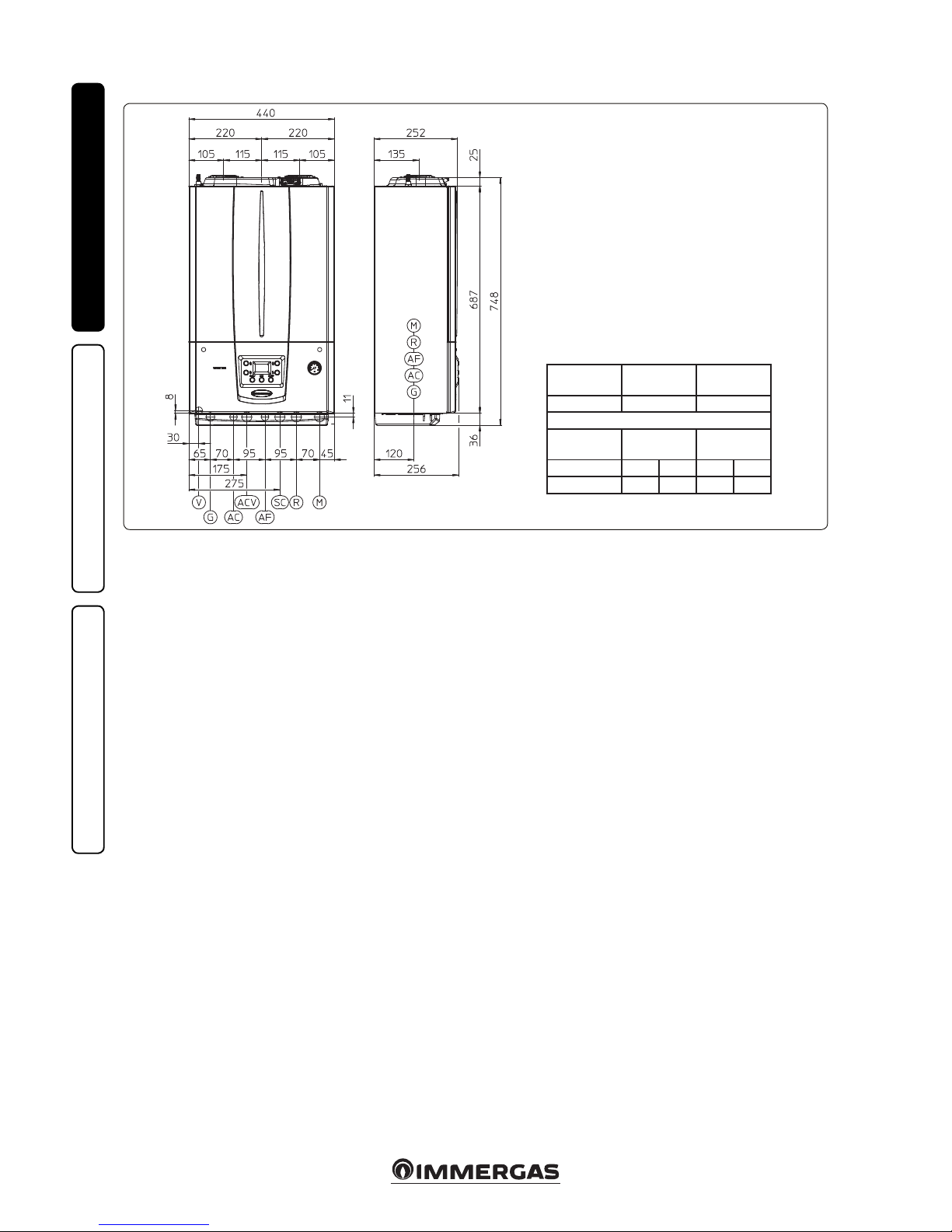
1.2 MAIN DIMENSIONS.
Key:
V - Electrical connection
G - Gas supply
AC - Domestic hot water outlet
ACV - Solar valve kit DHW inlet
(optional)
AF - Domestic hot water inlet
SC - Condensate drain (minimum
internal diameter Ø 13 mm)
M - System ow
R - System return
Height
(mm)
Width (mm) Depth (mm)
748 440 256
CONNECTIONS
GAS
DOMESTIC
HOT WATER
SYSTEM
G AC AF R M
3/4” 1/2” 1/2” 3/4” 3/4”
1.3 ANTIFREEZE PROTECTION.
Minimum temperature -5°C. e boiler comes
standard with an antifreeze function that activates the pump and burner when the system
water temperature in the boiler falls below 4°C.
In these conditions the boiler is protected against
freezing to an ambient temperature of -5°C.
Minimum temperature -15°C. If the boiler is
installed in a place where the temperature drops
below -5°C, the appliance can freeze.
To prevent the risk of freezing follow the instructions below:
- protect the central heating circuit from freezing
by inserting a good-quality antifreeze liquid
into this circuit, which is specially suited for
central heating systems and which is manufacturer guaranteed not to cause damage to
the heat exchanger or other components of
the boiler. e antifreeze liquid must not be
harmful to one's health. e instructions of the
manufacturer of this liquid must be followed
scrupulously regarding the percentage necessary with respect to the minimum temperature
at which the system must be kept. An aqueous
solution must be made with potential pollution
class of water 2 (EN 1717:2002 or local standards in force).
e materials used for the central heating circuit
of Immergas boilers withstand ethylene and
propylene glycol based antifreeze liquids (if the
mixtures are prepared perfectly).
For life and possible disposal, follow the sup-
plier's instructions.
- Protect the domestic hot water circuit against
freezing by using an accessory that is supplied
on request (antifreeze kit) comprising two
electric heating elements, the relevant wiring
and a control thermostat (carefully read the
installation instructions contained in the accessory kit pack).
In these conditions the boiler is protected against
freezing to temperature of -15°C.
Boiler antifreeze protection (both -5°C and -15°C)
is thus ensured only if:
- the boiler is correctly connected to gas and electricity power supply circuits;
- the boiler is powered constantly;
- the boiler is not in “o” mode.
- the boiler is not in anomaly conditions (Parag.
2.5);
- the essential components of the boiler and/or
antifreeze kit are not faulty.
e warranty does not cover damage due to interruption of the electrical power supply and failure
to comply with that stated on the previous page.
N.B.: if the boiler is installed in places where
the temperature falls below 0°C the domestic
hot water and central heating attachment pipes
must be insulated.
Page 7

7
3
4
5
1
2
3
3
1
4
2
2
1
4
5
6
5
6
INSTALLERUSERMAINTENANCE TECHNICIAN
1.4 INSTALLATION INSIDE A
RECESSED FRAME OPTIONAL.
e boiler is designed for installation inside the
Immergas recessed frame (supplied as optional).
e necessary parts for this type of installation
(brackets) must also be purchased separately as
optional kit.
To install proceed as follows:
- Install the bracket (2) inside the recessed frame
xing it with the screws (3) in the pre-drilled
holes (Fig. 3).
- Hang the boiler (4) to the bracket (2) (Fig. 4).
- Block the boiler (4) by mounting the brackets
(5) and xing them with their screws (6) (Fig.
5).
e brackets (5) used to centre the boiler on
the frame and hold it in place stop against the
frame (1) so do not require xing to the frame
itself.
Page 8
8
1
2
3
G
V
AC
AF
R
SC
M
6
INSTALLERUSERMAINTENANCE TECHNICIAN
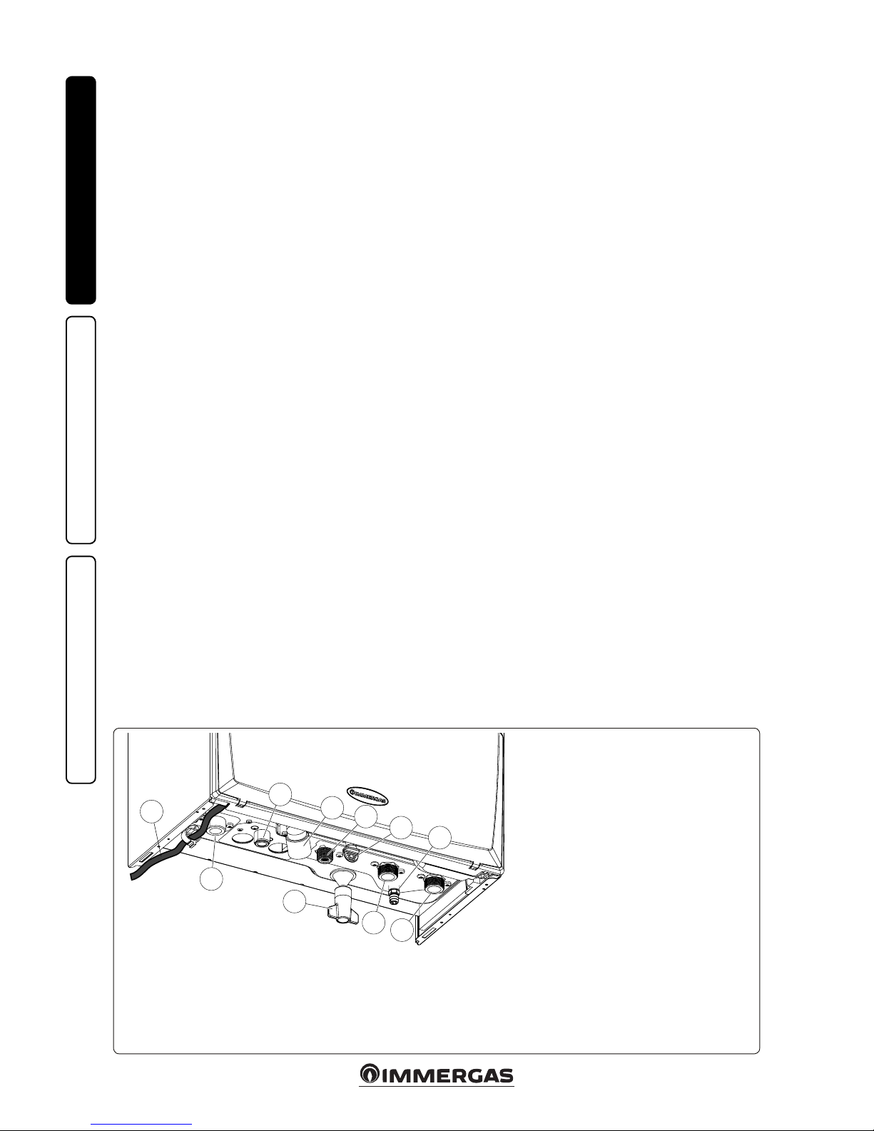
Key:
V - Electrical connection
G - Gas supply
AC - Domestic hot water outlet
AF - Domestic hot water inlet
SC - Condensate drain (minimum internal diame-
ter Ø 13 mm)
M - System ow
R - System return
1 - System lling valve
2 - System draining valve
3 - 3 bar safety valve drain tting signal
1.5 BOILER CONNECTION UNIT.
e connection unit consisting of all the necessary parts to perform the hydraulic and gas
system connections of the appliance comes as
optional kit, perform the connections respecting
the arrangement of Fig. 6 based on the type of
installation to be made.
1.6 GAS CONNECTION.
Our boilers are designed to operate with methane
gas (G20) and LPG. Supply pipes must be the
same as or larger than the 3/4”G boiler tting.
Before connecting the gas line, carefully clean
inside all the fuel feed system pipes to remove
any residue that could impair boiler eciency.
Also make sure the gas corresponds to that for
which the boiler is prepared (see boiler data
nameplate). If dierent, the boiler must be converted for operation with the other type of gas
(see converting appliance for other gas types). It
is also important to check the dynamic pressure
of the mains (methane or LPG) used to supply the
boiler, which must comply with EN 437 and its
attachment, as insucient levels may reduce generator output and cause discomfort to the user.
Ensure correct gas cock connection. e gas
supply pipe must be suitably dimensioned
according to current regulations in order to
guarantee correct gas ow rate to the burner even
in conditions of maximum generator output and
to guarantee appliance eciency (technical specications). e coupling system must conform to
standards in force.
Fuel gas quality. e appliance was designed to
operate with combustible gas free of impurities;
otherwise it is advisable to fit special filters
upstream of the appliance to restore the purity
of the fuel.
Storage tanks (in case of supply from LPG
depot).
- New LPG storage tanks may contain residual
inert gases (nitrogen) that degrade the mixture
delivered to the appliance casing functioning
anomalies.
- Due to the composition of the LPG mixture,
layering of the mixture components may occur
during the period of storage in the tanks. is
can cause a variation in the heating power of
the mixture delivered to the appliance, with
subsequent change in its performance.
1.7 HYDRAULIC CONNECTION.
Attention: in order not to void the condensa-
tion module warranty, before making the boiler
connections, carefully wash the heating system
(pipes, radiators, etc.) with special pickling or
descaling products to remove any deposits that
could compromise correct boiler operation.
A treatment of the heating and water system
water is required, in compliance with the technical standards in force, in order to protect the
system and the appliance from deposits (e.g.
scale), slurry or other hazardous deposits. In
order not to void the heat exchanger warranty,
you are required to comply with what has been
prescribed in Paragraph 1.23.
Water connections must be made in a rational
way using the couplings on the boiler template.
Attention: Immergas declines all liability in the
event of damage caused by the installation of an
automatic lling system.
In order to meet the system requirements established by EN 1717 in terms of pollution of
drinking water, we recommend installing the
IMMERGAS anti-backow kit to be used upstream of the cold water inlet connection of the
boiler. We also recommend using a category 1, 2
or 3 heat transfer uid (ex: water + glycol) in the
boiler's primary circuit (C.H. circuit), as dened
in standard EN 1717.
Attention: to preserve the duration and the eciency features of the appliance, in the presence
of water whose features can lead to the deposit of
scale, installation of the “polyphosphate dispenser”
kit is recommended.
3 bar safety valve. Discharge of the safety valve
has been conveyed to the condensate drain trap
outlet. Consequently, in the event of valve intervention, the discharged liquid will end up in
the sewer system through the drain pipe of the
condensate drain trap.
In any case the lower part of the appliance is
tted with a drain tting (Ref. 3 Fig. 6) with the
relative closure cap to check for the presence of
liquid in the discharge circuit and to check the
intervention of the 3 bar safety valve.
Condensate drain. To drain the condensate produced by the appliance, it is necessary to connect
to the drainage system by means of acid condensate resistant pipes, with an internal Ø of at least
13 mm. e system connecting the appliance to
the drainage system must be carried out in such
a way as to prevent occlusion and freezing of the
liquid contained in it. Before appliance ignition,
ensure that the condensate can be correctly removed. Aer rst ignition, check that the drain
trap is lled with condensate (Para. 1.25). Also,
comply with national and local regulations on
discharging waste waters.
In the event condensate is not discharged into
the wastewater drainage system, a condensate
neutraliser must be installed to ensure compliance with the parameters established by the
legislation in force.
Page 9
9
7
8
b
2
3
d
a
1
c
2
INSTALLERUSERMAINTENANCE TECHNICIAN
1.8 ELECTRICAL CONNECTION:
e appliance has an IPX5D protection degree;
electrical safety of the appliance is achieved only
when it is connected properly to an ecient
earthing system, as specied by current safety
standards.
Attention: Immergas S.p.A. declines any responsibility for damage or physical injury caused by
failure to connect the boiler to an ecient earth
system or failure to comply with the reference
standards.
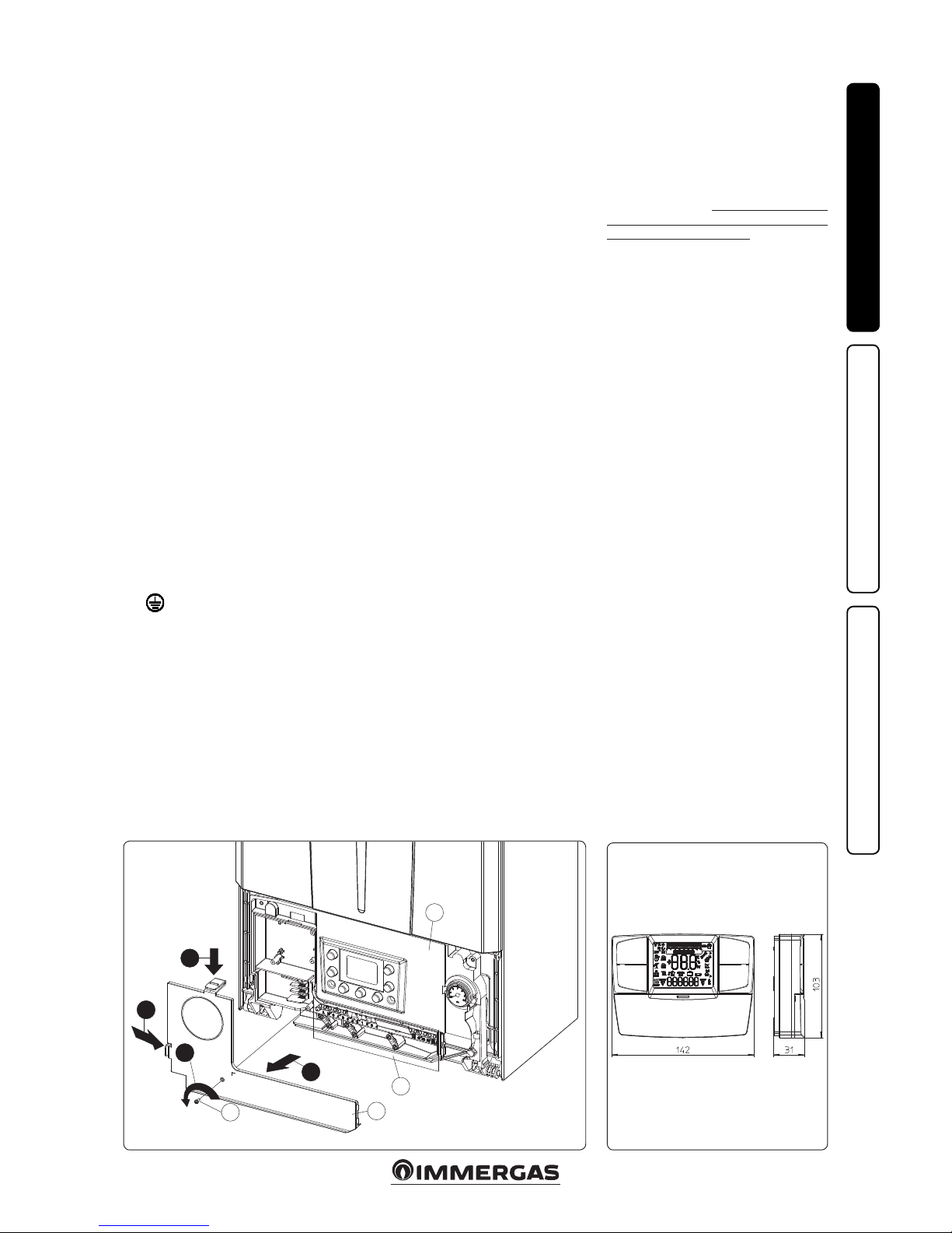
• Open the control panel connections compartment (Fig. 7).
To carry out electrical connections, all you have
to do is open the connections compartment as
follows (Fig. 7):
- Disassemble the cover (Fig. 53).
- Disassemble the cover (b)
1) Loosen the screw (a).
2) Press the two hooks on the connections
compartment cover.
3) Remove the cover (b) from the control
panel (c).
- At this point, it is possible to access the terminal
board (d).
Also ensure that the electrical installation corresponds to maximum absorbed power specications as shown on the boiler data nameplate.
Boilers are supplied complete with an “X” type
power cable without plug. e power supply cable
must be connected to a 230V ±10% / 50Hz mains
supply respecting L-N polarity and earth connection; this network must also have a multi-pole
circuit breaker with class III overvoltage category.
To protect from possible dispersions of DC voltage, it is necessary to provide a type A dierential
safety device.
When replacing the power supply cable, contact a
qualied company (e.g. the Immergas Authorised
Aer-Sales Technical Assistance Service). e
power cable must be laid as shown (Fig. 6).
In the event of mains fuse replacement on the
P.C.B., use a 3.15A quick-blow fuse. For the
main power supply to the appliance, never use
adapters, multiple sockets or extension leads.
Installation with system operating at direct
low temperature. e boiler can directly supply
a low-temperature system by setting the ow
temperature adjustment range “t0” and “t1” (Par.
3.8). In this situation it is good practice to insert
a relevant safety kit (optional) made up from a
thermostat (with adjustable temperature). e
thermostat must be positioned on the system
ow pipe at a distance of at least 2 metres from
the boiler.
1.9 REMOTE CONTROLS AND
ROOM CHRONOTHERMOSTATS
OPTIONAL.
e boiler is prepared for the application of room
chrono-thermostats or remote controls, which
are available as optional kits (Fig. 8).
All Immergas chrono-thermostats are connected
with 2 wires only. Carefully read the user and
assembly instructions contained in the accessory kit.
• On/O Immergas digital chrono-thermostat.
e chrono-thermostat allows:
- set two room temperature value: one for day
(comfort temperature) and one for night
(reduced temperature);
- set a weekly programme with four daily
switch on and switch o times;
- selecting the required function mode from
the various possible alternatives:
• manual operation (with adjustable tempera-
ture).
• automatic operation (with set programme).
• forced automatic operation (momentarily
changing the temperature of the automatic
programme).
e chrono-thermostat is powered by two 1.5V
LR 6 type alkaline batteries.
• Comando Amico Remoto Remote Control De-
vice V2 (CARV2) with climate chrono-thermostat
function. In addition to the functions described
in the previous point, the CARV2 panel enables
the user to control all the important information regarding operation of the appliance and
the heating system with the opportunity to
easily intervene on the previously set parameters, without having to go to where the appliance is installed. e panel is provided with
self-diagnosis to display any boiler functioning
anomalies. The climate chrono-thermostat
incorporated into the remote panel enables
the system ow temperature to be adjusted to
the actual needs of the room being heated, in
order to obtain the desired room temperature
with extreme precision and therefore with
evident saving in running costs. e CARV2 is
fed directly by the boiler by means of the same 2
wires used for the transmission of data between
the boiler and device.
Comando Amico Remoto Remote Control V2
or On/O chrono-thermostat electrical connections (Optional). e operations described
below must be performed aer having removed
the voltage from the appliance. Any thermostat
or On/O environment chrono-thermostat must
be connected to clamps 44/40 and 41 eliminating
jumper X40 (Fig. 38). Make sure that the On/
O thermostat contact is of the “clean” type, i.e.
independent of the mains voltage, otherwise the
P.C.B. would be damaged. Any Comando Amico
Remoto Remote Control V2 must be connected
to clamps 44/40 and 41 eliminating jumper X40
on the P.C:B., paying attention not to invert the
polarity in the connections (Fig. 38). e boiler
can only be connected to one remote control.
Important: if the Comando Amico Remoto Remote Control V2 or any other On/Off
chrono-thermostat is used, arrange two separate
lines in compliance with current regulations
regarding electrical systems. No boiler pipes
must ever be used to earth the electric system or
telephone lines. Ensure elimination of this risk
before making the boiler electrical connections.
Page 10

10
45
31
58
9
INSTALLERUSERMAINTENANCE TECHNICIAN
EXTERNAL PROBE
Correction law of the ow temperature depending on the external temperature
and user adjustments of the central heating temperature.
1.10 EXTERNAL TEMPERATURE PROBE
OPTIONAL.
e boiler is designed for the application of the
external temperature probe (Fig. 9), which is
available as an optional kit. Refer to the relative
instruction sheet for positioning of the external
probe.
e probe can be connected directly to the boiler
electrical system and allows the max. system ow
temperature to be automatically decreased when
the external temperature increases, in order to
adjust the heat supplied to the system according
to the change in external temperature. e external probe always operates when connected,
regardless of the presence or type of room
chrono-thermostat used and can work in combination with Immergas chrono-thermostats. e
correlation between system ow temperature
and external temperature is determined by the
position of the central heating selector switch on
the boiler control panel (or on the CARV2 control
panel if connected to the boiler) according to
the curves shown in the diagram (Fig. 10). e
electric connection of the external probe must be
made on clamps 38 and 39 on the terminal board
in the boiler control panel (Fig. 38).
10
Position of the central heating temperature
user adjustment
Page 11
11
(A)
(B)
11
INSTALLERUSERMAINTENANCE TECHNICIAN
1.11 IMMERGAS FLUE SYSTEMS.
Immergas supplies various solutions separately
from the boilers regarding the installation of
air intake terminals and ue exhaust, which are
fundamental for boiler operation.
Attention: the boiler must be installed exclusively with an original Immergas “Green
Range” inspectionable air intake system and
flue gas extraction system made of plastic,
with the exception of the C6 conguration, as
required by the regulations in force.
e plastic pipes cannot be installed outdoors,
for tracts longer than 40 cm, without suitable
protection from UV rays and other atmospheric agents.
is ue can be identied by an identication
mark and special distinctive marking bearing
the note "only for condensation boilers".
• Resistance factors and equivalent lengths. Each
ue component has a Resistance Factor based
on experimental tests and specied in the table
below. e Resistance Factor for individual
components is independent from the type of
boiler on which it is installed and has a dimensionless size. It is however, conditioned by the
temperature of the uids that pass through the
pipe and therefore, varies according to applications for air intake or ue exhaust. Each single
component has a resistance corresponding to
a certain length in metres of pipe of the same
diameter; the so-called equivalent length,
can be obtained from the ratio between the
relative Resistance Factors. All boilers have an
experimentally obtainable maximum Resistance
Factor equal to 100. e maximum Resistance
Factor allowed corresponds to the resistance
encountered with the maximum allowed pipe
length for each type of Terminal Kit. This
information allows calculations to be made to
verify the possibility of setting up various ue
congurations.
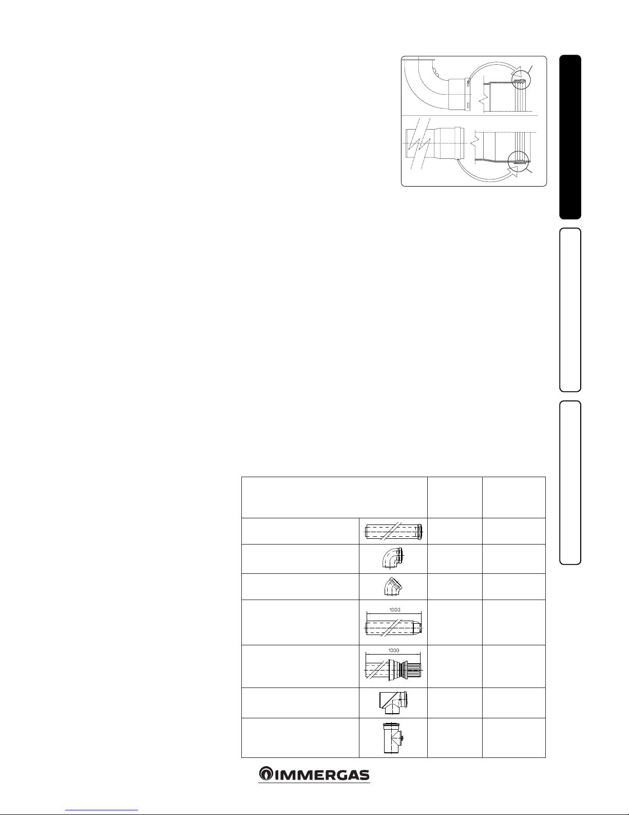
• Positioning of the gaskets (black) for “green
range” ue extraction systems. Position the
gasket correctly (for bends and extensions)
(Fig. 11):
- gasket (A) with notches, to use for bends;
- gasket (B) without notches, to use for exten-
sions;
N.B.: if necessary, to ease the push-fitting,
spread the elements with commonly-used talc.
• Coupling extension pipes and concentric
elbows. To install push-tting extensions with
other elements of the ue, proceed as follows:
Install the concentric pipe or elbow with the
male side (smooth) on the female side (with lip
seal) to the end stop on the previously installed
element in order to ensure sealing eciency of
the coupling.
Attention: if the exhaust terminal and/or
concentric extension pipe needs shortening,
consider that the internal duct must always
protrude by 5 mm with respect to the external
duct.
• N.B.: for safety purposes, do not obstruct the
boiler intake/exhaust terminal, even temporaril y.
• N.B.: when installing horizontal pipes, a min-
imum inclination of 3% must be maintained
and a section clip with pin must be installed
every 3 metres.
• Installation inside the recessed frame. In this
mode, install the ue according to your needs
using the appropriate pre-sections in the frame
to exit from its clearances.
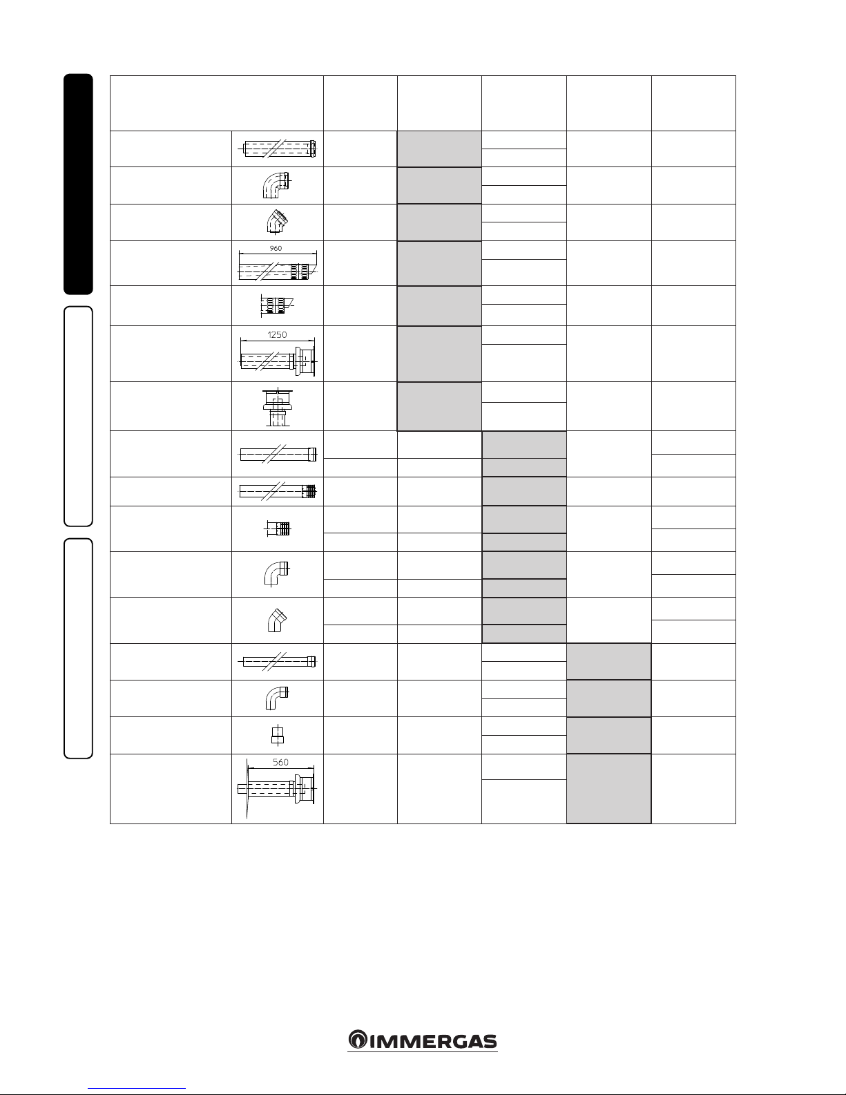
1.12 TABLES OF RESISTANCE FACTORS
AND EQUIVALENT LENGTHS.
TYPE OF DUCT
Resistance
Factor
(R)
Equivalent length
in m of concentric
pipe Ø 80/125
Concentric pipe 80/125 Ø m 1
2.1
1
Concentric bend 90° 80/125 Ø
3.0
1.4
Concentric bend 45° 80/125 Ø
2.1
1
Terminal complete with concentric
horizontal intake-exhaust Ø 80/125
2.8
1.3
Terminal complete with concentric
vertical intake-exhaust 80/125 Ø
3.6
1.7
Concentric bend 90° Ø 80/125 with
inspection
3.4
1.6
Stub pipe with inspection Ø 80/125
3.4
1.6
Page 12
12
INSTALLERUSERMAINTENANCE TECHNICIAN
TYPE OF DUCT
Resistance
Factor
(R)
Equivalent length
in m of concentric
pipe Ø 60/100
Equivalent length
in metres of pipe
Ø 80
Equivalent length
in metres of pipe
60 Ø
Equivalent length
in m of concentric
pipe Ø 80/125
Concentric pipe Ø 60/100
m 1
Intake and
Exhaust 6.4
m 1
Intake m 7.3
Exhaust m 1.9 m 3.0
Exhaust m 5.3
Concentric bend 90° Ø
60/100
Intake and
Exhaust 8.2
1.3 m
Intake m 9.4
Exhaust m 2.5 m 3.9
Exhaust m 6.8
Concentric bend 45° Ø
60/100
Intake and
Exhaust 6.4
m 1
Intake m 7.3
Exhaust m 1.9 m 3.0
Exhaust m 5.3
Terminal complete with
concentric horizontal
intake-exhaust Ø 60/100
Intake and
Exhaust 15
m 2.3
Intake m 17.2
Exhaust m 4.5 m 7.1
Exhaust m 12.5
Concentric horizontal
intake- exhaust terminal
Ø 60/100
Intake and
Exhaust 10
m 1.5
Intake m 11.5
Exhaust m 3.0 4.7 m
Exhaust m 8.3
Terminal complete with
concentric vertical intake-exhaust Ø 60/100
Intake and
Exhaust 16.3
m 2.5
Intake m 18.7
Exhaust m 4.9 m 7.7
Exhaust m 13.6
Concentric vertical
intake-exhaust terminal Ø
60/100
Intake and
Exhaust 9
1.4 m
Intake m 10.3
Exhaust m 2.7 m 4.3
Exhaust m 7.5
Pipe Ø 80 m 1
Intake 0.87 m 0.1 Intake m 1.0
Exhaust m 0.4
m 0.4
m 0.5
Exhaust 1.2 m 0.2 Exhaust m 1.0
Complete intake terminal
Ø 80 m 1
Intake 3 m 0.5 Intake m 3.4 Exhaust m 0.9 1.4 m
Intake terminal Ø 80
Exhaust terminal Ø 80
Intake 2.2 m 0.35 Intake m 2.5
Exhaust m 0.6
m 1
m 0.9
Exhaust 1.9 m 0.3 Exhaust m 1.6
Bend 90° 80 Ø
Intake 1.9 m 0.3 Intake m 2.2
Exhaust m 0.8
m 0.9
m 1.2
Exhaust 2.6 m 0.4 Exhaust m 2.1
45° 80 Ø Bend
Intake 1.2 m 0.2 Intake m 1.4
Exhaust m 0.5
m 0.5
0.7
Exhaust 1.6 m 0.25 Exhaust m 1.3
Pipe Ø 60 m 1 for ducting Exhaust 3.3 m 0.5
Intake 3.8
Exhaust m 1.0 m 1.5
Exhaust 2.7
Bend 90° Ø 60 for ducting
Exhaust 3.5 m 0.55
Intake 4.0
Exhaust m 1.1 1.6 m
Exhaust 2.9
Reduction Ø 80/60
Intake and
Exhaust 2.6
m 0.4
Intake m 3.0
Exhaust m 0.8 m 1.2
Exhaust m 2.1
Terminal complete with
exhaust
vertical Ø 60 for ducting
Exhaust 12.2 1.9 m
Intake m 14
Exhaust m 3.7 m 5.8
Exhaust m 10.1
Page 13
13
12
13 14
INSTALLERUSERMAINTENANCE TECHNICIAN
1.13 OUTDOOR INSTALLATION IN
PARTIALLY PROTECTED AREA.
N.B.: a partially protected location is one in which
the appliance is not exposed to the direct action of
the weather (rain, snow, hail, etc..)..
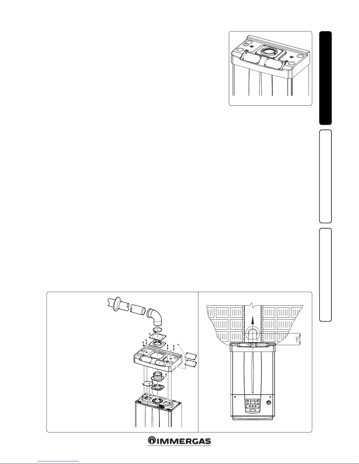
• Conguration type B, open chamber and fan
assisted.
Using the special coverage kit one can achieve
direct air intake (Fig. 12) and ue gas exhaust
in a single chimney or directly outside. In this
conguration it is possible to install the boiler in
a partially protected place. In this conguration
the boiler is classied as type B.
With this conguration:
- air intake takes place directly from the envi-
ronment in which the appliance is installed
(external);
- the ue gas exhaust must be connected to its
own single ue (B23) or ducted directly outside
via a vertical terminal for direct exhaust (B53)
or via an Immergas ducting system (B53).
The technical regulations in force must be
respected.
• Coverage kit assembly (Fig. 13). Remove the
two plugs from the lateral intake holes. Now
cover the le intake hole using the relevant
plate, xing it onto the right side using the 2
previously-removed screws. Install the Ø 80
outlet ange on the central hole of the boiler,
taking care to insert the gasket supplied with
the kit and tighten by means of the screws
provided. Install the upper cover, xing it using
the 4 screws present in the kit, positioning the
relevant gaskets. Engage the 90° Ø 80 bend
with the male end (smooth) in the female end
(with lip seal) of the Ø 80 ange unit until
it stops. Introduce the gasket, making it run
along the bend. Fix it using the metal sheet
plate and tighten by means of the clips present
in the kit, making sure to block the 4 gasket
aps. Fit the male end (smooth) of the exhaust
terminal into the female end of the bend 90° Ø
80, making sure that the relevant wall sealing
plate is already tted; this will ensure hold and
joining of the elements making up the kit.
Max. length of exhaust duct. e ue pipe (both
vertical or horizontal) can be extended to a max.
length of 30 linear metres.
• Coupling of extension pipes. To install
push-tting extensions with other elements
of the ue, proceed as follows: Install the pipe
or elbow with the male side (smooth) in the
female section (with lip seal) to the stop on the
previously installed element. is will ensure
sealing eciency of the coupling.
• Conguration without cover kit in a partially
protected location (type C boiler)
N.B.: a partially protected location is one in
which the appliance is not exposed to the direct
action of the weather (rain, snow, hail, etc..)..
By leaving the side plugs tted it is possible
to install the appliance externally without the
cover kit. Installation takes place using the
Ø60/100 and Ø 80/125 concentric intake/
exhaust kits. Refer to the paragraph on indoor
installation. In this conguration the upper
cover kit guarantees additional protection for
the boiler. It is recommended but not compulsory. e Ø 80/80 separating device cannot be
used in this conguration.
e cover kit includes:
N° 1 Heat moulded cover
N°1 Gasket clamping plate
N°1 Gasket
N°1 Gasket clamp
N°1 N°1 Intake hole covering plate
e terminal kit includes:
N° 1 Gasket
N° 1 Exhaust ange Ø 80
N° 1 Bend 90° 80 Ø
N° 1 Exhaust pipe Ø 80
N° 1 Wall sealing plate
Page 14
14
15
16
INSTALLERUSERMAINTENANCE TECHNICIAN
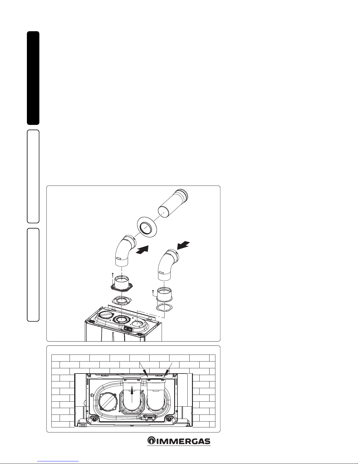
1.14 INTERNAL INSTALLATION USING
A RECESSED FRAME WITH DIRECT
AIR INTAKE
• Conguration type B, open chamber and fan
assisted.
Using a kit separator one can achieve direct air
intake (Fig. 16) and ue gas exhaust in a single
chimney or directly outside. In this conguration
the boiler is classied as type B23.
With this conguration:
- air intake takes place directly from the envi-
ronment in which the appliance is installed
(the recessed frame is ventilated), and only
functions in permanently ventilated rooms;
- the ue gas exhaust must be connected to its
own individual ue or channelled directly into
the external atmosphere.
The technical regulations in force must be
respected.
Separator kit installation: install the discharge
ange on the central hole of the boiler, positioning the relative gasket with the circular
projections downwards in contact with the
boiler ange, and tighten using the hex screws
with at tip contained in the kit. Remove the at
ange present in the lateral hole with respect to
the central one (according to needs) and replace
it with the intake ange, positioning its gasket
already present in the boiler and tighten using
the supplied self-threading screws. Fit the male
side (smooth) to the bends in the female side of
the anges.
e intake bend must face the rear side of the
boiler.
Fit the exhaust pipe with the male side (smooth)
to the female side of the bend up to the end stop,
making sure that the internal wall sealing plate
has been tted and connecting the required ue
according to personal requirements.
Max. length of exhaust duct. e ue pipe (both
vertical or horizontal) can be extended to a max.
length of 30 linear metres.
Page 15
15
C
13
C
13
C
13
5
4
3
1
2
1
2
3
4
5
6
C
13
17 18
19 20
INSTALLERUSERMAINTENANCE TECHNICIAN
e kit includes:
N° 1 - Gasket (1)
N° 1 - Concentric bend Ø 60/100 (2)
N° 1 - Int./exhaust concentric terminal Ø 60/100 (3)
N° 1 - Internal wall sealing plate (4)
N° 1 - External wall sealing plate (5)
e adaptor kit includes:
N° 1 - Gasket (1)
N° 1 - Adapter Ø 80/125 (2)
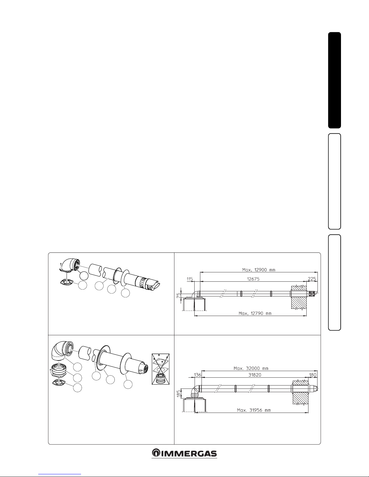
1.15 CONCENTRIC HORIZONTAL KIT
INSTALLATION.
Type C configuration, sealed chamber and
fan assisted.
e position of the terminal (in terms of distances from openings, overlooking buildings, oor,
etc.) must be in compliance with the regulations
in force.
is terminal is connected directly to the outside
of the building for air intake and ue gas exhaust.
e horizontal kit can be installed with the rear,
right side, le side or front outlet. For installation
with frontal outlet, one must use the xing plate
and a concentric bend coupling in order to ensure
sucient space to carry out the tests required by
law upon commissioning.
• External grid. Both the Ø 60/100 and Ø 80/125
intake/exhaust terminal, if properly installed, is
pleasant to look at on the outside of the building. Make sure that the external silicone wall
sealing plate is properly inserted in the wall.
N.B.: for proper system operation the terminal
with grid must be installed correctly ensuring
that, the "high" indication on the terminal is
observed during installation.
Horizontal intake-exhaust kit Ø 60/100. Kit
assembly (Fig. 17): install the bend with ange
(2) on the central hole of the boiler, positioning
gasket (1) with the circular projections downwards in contact with the boiler flange, and
tighten using the screws present in the kit. Fit
the Ø 60/100 (3) concentric terminal pipe with
the male side (smooth) to the female side of the
bend (2) up to the end stop; making sure that the
internal and external wall sealing plate have been
tted, this will ensure sealing and joining of the
elements making up the kit.
• Extensions for Ø 60/100 horizontal kit (Fig. 18).
e kit with this conguration can be extended
up to a max. 12.9 horizontal m including the
terminal with grid and excluding the concentric bend leaving the boiler. is conguration
corresponds to a resistance factor of 100. In this
case the special extensions must be requested.
Immergas also provides a Ø 60/100 simplied
terminal, which in combination with its extension kits allows you to reach a maximum
extension of 11.9 metres.
Horizontal intake-exhaust kit Ø 80/125. Kit
assembly (Fig. 19): to install the kit Ø 80/125
one must use the anged adapter kit in order
to install the ue system Ø 80/125. Install the
anged adaptor (2) on the central hole of the
boiler, positioning gasket (1) with the circular
projections downwards in contact with the boiler
ange, and tighten using the screws contained in
the kit. Engage the bend (3) with the male side
(smooth) to the end stop on the adapter (1). Fit
the Ø 80/125 (5) concentric terminal pipe with
the male side (smooth) to the female side of the
bend (4) (with lip seals) up to the end top; making
sure that the internal (6) and external wall sealing
plate (7) have been tted, this will ensure sealing
and joining of the elements making up the kit.
• Extensions for Ø 80/125 horizontal kit (Fig. 20).
e kit with this conguration can be extended
up to a max. length of 32 m, including the terminal with grid and excluding the concentric bend
leaving the boiler. If additional components
are assembled, the length equivalent to the
maximum allowed must be subtracted. In this
case the special extensions must be requested.
e Kit Ø 80/125 includes:
N° 1 - Concentric bend Ø 80/125
at 87° (3)
N° 1 - Concentric intake-exhaust
terminal Ø 80/125 (4)
N ° 1 - Internal wall sealing plate (5)
N ° 1 - External wall sealing plate (6)
e remaining kit components
must not be used
Page 16
16
C
33
C
33
C
33
C
33
7
4
6
5
1
2
3
1
2
3
4
5
6
7
21 22
23 24
INSTALLERUSERMAINTENANCE TECHNICIAN
e Kit includes:
N° 1 - Gasket (1)
N° 1 - Female concentric ange (2)
N° 1 - Wall sealing plate (3)
N° 1 - Aluminium tile (4)
N° 1 - Int./exhaust concentric pipe Ø
60/100 (5)
N° 1 - Fixed half-shell (6)
N° 1 - Mobile half-shell (7)
e adaptor kit includes:
N° 1 - Gasket (1)
N° 1 - Adapter
Ø 80/125 (2)
e Kit Ø 80/125 includes:
N° 1 - Wall sealing plate (3)
N° 1 - Aluminium tile (4)
N° 1 - Fixed half-shell (5)
N° 1 - Mobile half-shell (6)
N° 1 - Concentric intake-exhaust
terminal Ø 80/125 (7)
e remaining kit components
must not be used
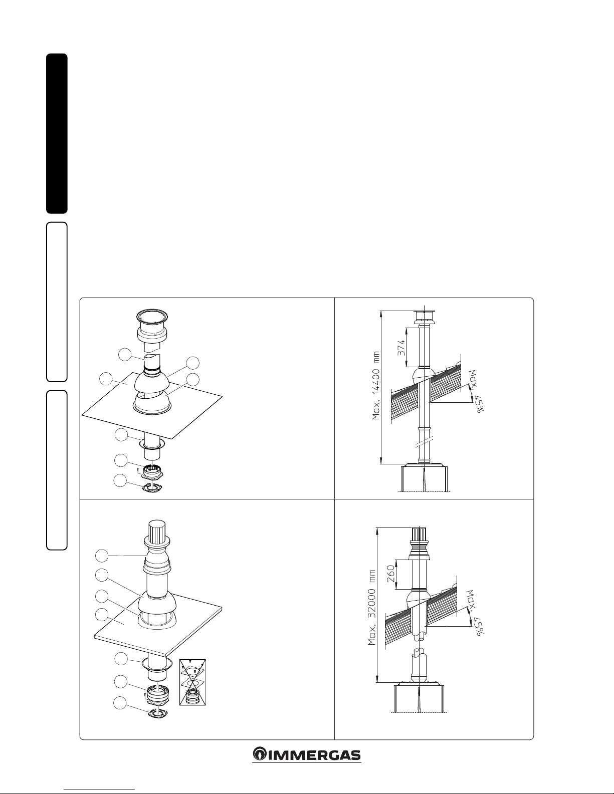
1.16 CONCENTRIC VERTICAL KIT
INSTALLATION.
Type C configuration, sealed chamber and
fan assisted.
Concentric vertical intake and exhaust kit. is
vertical terminal is connected directly to the
outside of the building for air intake and ue
gas exhaust.
N.B.: the vertical kit with aluminium tile enables
installation on terraces and roofs with a maximum slope of 45% (approx 25°) and the height
between the terminal cap and half-shell (374 mm
for Ø 60/100 and 260 mm for Ø 80/125) must
always be observed.
Vertical kit with aluminium tile Ø 60/100.
Kit assembly (Fig. 21): install the concentric
ange (2) on the central hole of the boiler, positioning gasket (1) with the circular projections
downwards in contact with the boiler ange, and
tighten using the screws contained in the kit.
Installation of the fake aluminium tile: replace
the tiles with the aluminium sheet (4), shaping
it to ensure that rainwater runs o. Position
the xed half-shell (6) on the aluminium tile
and insert the intake-exhaust pipe (5). Fit the
Ø 60/100 (3) concentric terminal pipe with the
male side (5) (smooth) into the ange (2) up to
the end stop; making sure that the wall sealing
plate has been tted (3), this will ensure sealing
and joining of the elements making up the kit.
N.B.: when the boiler is installed in areas where
very cold temperatures can be reached, a special
anti-freeze kit is available that can be installed as
an alternative to the standard kit.
• Extensions for vertical kit Ø 60/100 (Fig. 22).
e kit with this conguration can be extended
to a max. straight vertical length of 14.4 m,
including the terminal. This configuration
corresponds to a resistance factor of 100. In
this case specic extensions must be requested.
Vertical kit with aluminium tile Ø 80/125.
Kit assembly (Fig. 23): to install the kit Ø 80/125
one must use the anged adapter kit in order
to install the ue system Ø 80/125. Install the
anged adaptor (2) on the central hole of the
boiler, positioning gasket (1) with the circular
projections downwards in contact with the boiler
ange, and tighten using the screws contained
in the kit. Installation of the fake aluminium
tile: replace the tiles with the aluminium sheet
(4), shaping it to ensure that rainwater runs o.
Position the xed half-shell (5) on the aluminium
tile and insert the intake-exhaust pipe (7). Fit the
Ø 80/125 concentric terminal pipe with the male
side (smooth) to the female side of the adapter (1)
(with lip gaskets) up to the end stop; making sure
that the wall sealing plate (3) has been tted, this
will ensure sealing and joining of the elements
making up the kit.
• Extensions for vertical kit Ø 80/125 (Fig. 24).
e kit with this conguration can be extended
up to a max. length of 32 m including the terminal. If additional components are assembled,
the length equivalent to the maximum allowed
must be subtracted. In this case specic extensions must be requested.
Page 17
17
C
83
C
43
1
4
7
9
5
5
6
7
8
3
2
S
A
C53* - C
83
25
26
27
* per completare la congurazione C53 prevedere anche un terminale di scarico a
tetto. Non è ammessa la congurazione su pareti opposte all'edicio.
INSTALLERUSERMAINTENANCE TECHNICIAN
e kit includes:
N° 1 - Exhaust gasket (1)
N° 1 - Flange gasket (2)
N° 1 - Female intake ange (3)
N° 1 - Female exhaust ange (4)
N° 2 - Bend 90° Ø 80 (5)
N° 1 - Intake terminal Ø 80 (6)
N° 2 - Internal wall sealing plates (7)
N° 1 - External wall sealing plate (8)
N° 1 - Exhaust pipe Ø 80 (9)
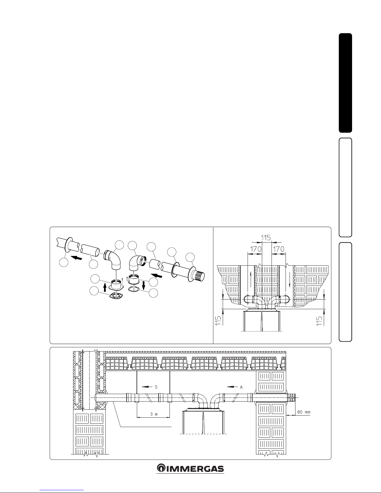
1.17 SEPARATOR KIT INSTALLATION.
Type C configuration, sealed chamber and
fan assisted.
Separator kit Ø 80/80. is kit allows air to come
in from outside the building and the exhaust to
exit from the chimney, ue or intubated duct
through divided ue exhaust and air intake pipes.
Combustion products are expelled from pipe (S)
(in plastic, so as to resist acid condensate). Air is
taken in through duct (A) for combustion (this
is also in plastic). e intake pipe (A) can be
installed either on the right or le hand side of
the central exhaust pipe (S). Both ducts can be
routed in any direction.
• Kit assembly (Fig. 25): install ange (4) on the
central hole of the boiler, positioning gasket
(1) with the circular projections downwards
in contact with the boiler ange, and tighten
using the hex screws with at tip contained
in the kit. Remove the at ange present in
the lateral hole with respect to the central one
(according to needs) and replace it with the
ange (3), positioning the gasket (2) already
present in the boiler and tighten using the
supplied self-threading screws. Fit the male side
(smooth) to the bends (5) in the female side of
the anges (3 and 4). Fit the intake terminal (6)
with the male side (smooth) in the female side
of the bend (5) up to the end stop, ensuring that
the internal and external wall sealing plates are
tted. Fit the exhaust pipe (9) with the male
end (smooth) to the female end of the bend
(5) up to the end stop; making sure that the
internal wall sealing plate has been tted, this
will ensure sealing and joining of the elements
making up the kit.
• Installation clearances (Fig. 26). e minimum
installation clearance measurements of the Ø
80/80 separator terminal kit have been stated
in some limit conditions.
• Extensions for separator kit Ø 80/80. The
maximum vertical straight length (without
bends) that can be used for Ø 80 intake and
exhaust pipes is 41 metres, regardless from
whether they are used for intake or exhaust.
e maximum horizontal straight length (with
bend in suction and in exhaust) that can be
used for Ø 80 intake and exhaust pipes is 36
metres, regardless from whether they are used
for intake or exhaust. Please note the type of
installation must be done with a natural
draught ue.
N.B.: to favour the removal of possible condensate forming in the exhaust pipe, tilt the pipes
towards the boiler with a minimum slope of
1.5% (Fig. 27).
C
43
Minimum slope 1.5%
Page 18
18
1
2
3
3
3
4
5
6
7
6
8
9
A
10
11
12
12
A
B
A
C
28
29
INSTALLERUSERMAINTENANCE TECHNICIAN
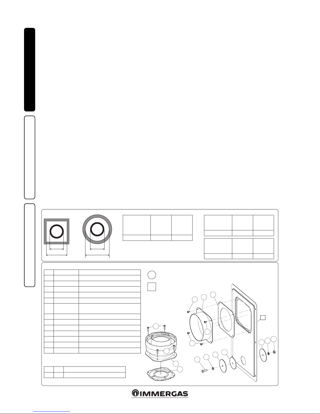
Kit composition:
Ref. Qty Description
1 1 Door adaptor Ø 100 or Ø 125
2 1 Door gasket made of neoprene
3 4 Screws 4.2 x 9 AF
4 1 Hex headed screw M6 x 20
5 1 Flat nylon washer M6
6 2 Door hole closure metal-sheet plate
plug
7 1 Plug gasket made of neoprene
8 1 Toothed washer M6
9 1 Nut M6
10 1 (kit 80/125) Concentric gasket Ø 60-100
11 1 (kit 80/125) Flanged adapter Ø 80-125)
12 4 (kit 80/125) Hex headed screws M4 x 16 slotted
- 1 (kit 80/125) Bag of lubricating talc
Installation drawings key:
Unique identication of the component in
the kit
Identication of the component not supplied
in this kit
1
A
Supplied separately:
Ref. Qty Description
A 1 Ducting kit door
Rigid Ø 80
ducting (A)
mm
SHAFT
(B) mm
SHAFT
(C) mm
86 126 146
Flexible Ø 80
ducting (A)
mm
SHAFT
(B) mm
SHAFT
(C) mm
90 130 150
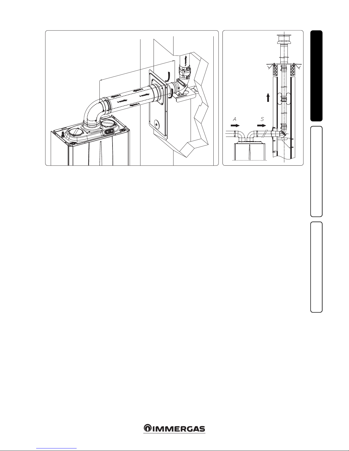
1.18 ADAPTOR C9 KIT INSTALLATION.
is kit allows an Immergas boiler to be installed
in "C93" conguration, with combustion air intake
directly from the sha where the ue gas exhaust
is, obtained by means of a ducting system.
System composition.
e system must be combined with the following
components (sold separately) to be functional
and complete:
- kit C93 Ø 100 or Ø125 version;
- rigid ducting Ø 60 and Ø 80 and exible Ø 50
and Ø 80 kit;
- ue exhaust kit Ø 60/100 or Ø 80/125 congured according to the installation and type of
boiler.
Kit Assembly.
- Mount the components of kit "C9" on the door
(A) of the ducting system (Fig. 29).
- (Version Ø 125 only) mount the anged adaptor (11) interposing the concentric gasket (10)
on the boiler, tting it with the screws (12).
- Mount the ducting system as described in the
relative instructions sheet.
- Calculate the distances between the boiler drain
and the bend of the ducting system.
- Prepare the boiler ue system, making sure that
the internal pipe of the concentric kit is tted
up to the end stop in the ducting system curve
(Quota "X" Fig. 30), whereas the external pipe
must reach the end stop of the adapter (1).
N.B.: to encourage the removal of possible
condensate forming in the exhaust pipe, tilt
the pipes towards the boiler with a minimum
slope of 1.5%.
- Mount the cover (A) complete with adaptor (1)
and caps (6) on the wall and assemble the ue
system to the ducting system.
N.B.: (version Ø 125 only) before assembly check
the gaskets are in the right position. In the event
component lubrication (already carried out
by the manufacturer) is not sucient, remove
the residual lubricant using a dry cloth, then
to ease tting coat the parts with common or
industrial talc.
Once all components have been assembled properly, the exhaust fumes will be expelled via the
ducting system; the combustion air for normal
boiler operation will be aspirated directly by the
sha (Fig. 30).
Technical data.
- e dimensions of the shas must ensure a
minimum gap between the outer wall of the
smoke duct and the inner wall of the sha: 30
mm for circular section shas and 20 mm in
the event of a square section sha (Fig. 28).
- Maximum 2 changes of direction are allowed
on the vertical section of the ue system with
a maximum clearance angle of 30° with respect
to the vertical.
- e maximum vertical extension using a Ø
60 ducting system is 13 m, the maximum
extension includes 1 bend Ø 60/10 at 90°, 1 m
of horizontal pipe 60/100, 1 90° ducted bend
Ø 60 and the roof terminal for ducting.
To determine the C
93
ue system in congurations other than that described (Fig. 30)
one must consider that 1 metre of ducted pipe
according to the indications described has a
resistance factor equal to 4.9.
- e maximum vertical extension using a Ø 80
ducting system is 28 m, the maximum extension includes 1 adapter 60/100 to 80/125, 1 87°
bend Ø 80/125, 1 m of horizontal pipe 80/125,
1 90° ducted bend Ø 80 and the roof terminal
for ducting.
To determine the C
93
ue system in congurations other than that described (Fig. 30) one
must consider the following pressure drops:
- 1 m of concentric pipe Ø 80/125 = 1 m of
ducted pipe;
- 1 87° bend = 1.4 m of ducted pipe;
Consequently one must subtract the equivalent
length of the part added to the 28 m available.
Flexible Ø 50
and Rigid Ø
60 ducting (A)
mm
SHAFT
(B) mm
SHAFT
(C) mm
66 106 126
Page 19
19
C
53
C
93
X
30
31
INSTALLERUSERMAINTENANCE TECHNICIAN
1.19 DUCTING OF FLUES OR
TECHNICAL SLOTS.
Ducting is an operation through which, via
the introduction of one or more relevant pipes,
one achieves a system for the evacuation of the
combustion products of a gas appliance, made up
from the coupling of an existing or new ducting
pipe with a chimney, ue or technical slot (also
in new buildings) (Fig. 31). Ducting requires
ducts declared to be suitable for the purpose by
the manufacturer, following the installation and
user instructions, provided by the manufacturer
and the requirements of the standards in force.
Immergas ducting system. e Ø 60 rigid, Ø
80 exible and Ø80 rigid “Green Range” ducting
systems must only be used for domestic use and
with Immergas condensing boilers.
In any case, ducting operations must respect
the provisions contained in the standard and in
current technical regulations; in particular, the
declaration of conformity must be compiled at
the end of work and on commissioning of the
ducted system. e instructions in the project
or technical report must likewise be followed, in
cases provided for by the standard and current
technical regulations. e system or components
of the system have a technical life complying with
current standards, provided that:
- it is used in average atmospheric and envi-
ronmental conditions, according to current
regulations, (absence of ue gas, dusts or gases
that can alter the normal thermophysical or
chemical conditions; existence of temperatures
coming within the standard range of daily
variation, etc.).
- Installation and maintenance must be per-
formed according to the indications supplied
by the manufacturer and in compliance with
the regulations in force.
- e maximum length specied by the manu-
facturer must be respected; in this regard:
- e max. possible length of the Ø 60 exible
ducting vertical section is equal to 22 m. is
length is obtained considering the complete
Ø 80 exhaust terminal, 1m of Ø 80 pipe in
exhaust, two 90° Ø 80 bends at boiler outlet.
- e max. possible length of the Ø 80 exible
ducting vertical section is equal to 30 m.
is length is obtained considering the Ø80
complete exhaust terminal, 1m of Ø 80 pipe
in exhaust, two 90° Ø 80 bends at boiler outlet
for connecting to the ducting system and two
direction changes of the exible hose inside
the chimney/technical slot.
- e max. possible length of the Ø 80 exible
ducting vertical section is equal to 30 m. is
length is obtained considering the complete
Ø 80 exhaust terminal, 1m of Ø 80 pipe in
exhaust, two 90° Ø 80 bends at boiler outlet.
You can also install an additional Ø50 exible
ducting system the specications of which are
found on the relevant instructions sheet inside
the kit.
1.20 CONFIGURATION TYPE B, OPEN
CHAMBER AND FAN ASSISTED FOR
INDOORS.
e appliance can be installed inside buildings
in 23 or B53 mode; in this case, all technical rules
and national and local regulations in force, must
be complied with.
- Type B open chamber boilers must not be
installed in places where commercial, artisan
or industrial activities take place, which use
products that may develop volatile vapours or
substances (e.g. acid vapours, glues, paints, solvents, combustibles, etc.), as well as dusts (e.g.
dust deriving from the working of wood, coal
nes, cement, etc.), which may be damaging for
the components of the appliance and jeopardise
functioning.
- in B23 and B53 conguration, unless otherwise
provided for by local regulations, the boilers
must not be installed in bedrooms, bathrooms
or in studio ats. ey must neither be installed
in rooms containing solid fuel heat generators
nor in rooms communicating with said rooms.
- Installation of appliances in B23 and B53 conguration is recommended in non-residential
premises and which are permanently ventilated.
For installation the cover kit must be used, referred to in Paragraph 1.13.
1.21 FLUE EXHAUST TO FLUE/CHIMNEY.
Flue exhaust does not necessarily have to be connected to a branched type traditional ue. e ue
exhaust, for boiler clots installed in C conguration,
can be connected to a special LAS type multiple ue.
For B23 congurations, exhaust is only allowed into
individual chimney or directly into the external
atmosphere via a relevant terminal. e multiple
ues and the combined ues must also only be
connected to type C appliances of the same type
(condensation), having nominal heat inputs that do
not dier by more than 30% less with respect to the
maximum that can be attached and powered by the
same fuel. e thermo-uid dynamic features (ue
ow rate, % of carbon dioxide, % humidity etc....) of
the appliances attached to the same multiple ues
or combined ues, must not dier by more than
10% with respect to the average boiler attached.
Multiple and combined ues must be specially
designed according to the calculation method and
requirements of the technical standards in force,
by a professionally qualied company. Chimney
or ue sections for connection of the ue exhaust
pipe must comply with requisites of technical
standards in force.
Page 20
20
32
INSTALLERUSERMAINTENANCE TECHNICIAN
1.22 FLUES, CHIMNEYS AND CHIMNEY
CAPS.
e ues, chimneys and chimney caps for the
evacuation of combustion products must be in
compliance with applicable standards. Chimneys
and roof-installed exhaust terminals must comply with the outlet height and with the distance
from technical volumes set forth by the technical
standards in force.
Positioning the wall ue exhaust terminals. e
wall ue exhaust terminals must:
- be installed on external perimeter walls of the
building;
- be positioned according to the minimum dis-
tances specied in current technical standards.
Combustion products exhaust of natural
draught or fan assisted appliances in open-top
closed environments. In spaces closed on all
sides with open tops (ventilation pits, courtyards etc.), direct combustion product exhaust
is allowed for natural draught or fan assisted gas
appliances with a heat input range from 4 to 35
kW, provided the conditions as per the current
technical standards are respected.
1.23 WATER TREATMENT SYSTEM
FILLING.
As already mentioned in the previous paragraphs, a treatment of the thermal and domestic
system water is required, in compliance with the
local standards in force.
e parameters that inuence the duration and
proper operation of the heat exchanger are the
water's PH, hardness, conductivity, and oxygen,
together with the system's processing residues
(any welding residues), any oil present and corrosion products that can, in turn, cause damage
to the heat exchanger.
In order to prevent this from happening, you are
recommended to:
- Before installation on new systems as well as
old ones, clean the system with clean water to
eliminate solid residues contained therein.
- Clean the system with a chemical treatment:
- Clean the new system with a suitable cleaning
device (for example Sentinel X300, Fernox
Cleaner F3 or Jenaqua 300) combined with
thorough washing.
- Clean the old system with a suitable cleaning
device (for example Sentinel X400 or X800,
Fernox Cleaner F3 or Jenaqua 400) combined
with thorough washing.
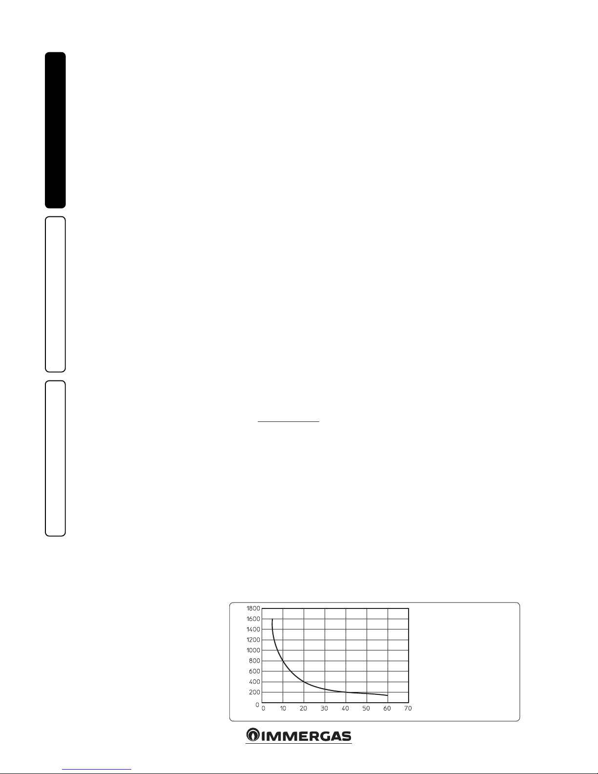
- Check the maximum hardness and quantity
of lling water referring to the graphics (Fig.
32). If the contents and hardness of the water
are below the indicated curve, no specific
treatment is required; otherwise, to limit the
content of calcium carbonate, you must provide
for water-lling treatment.
- For lling, you are not allowed to use water
soened with the use of ionic-exchange resins
or distilled water.
- Should you be required to provide for water
treatment, this should be carried out by
completely desalinating the lling water. As
opposed to the complete soening process,
desalinating the water completely not only
removes hardening agents (Ca, Mg), but also
eliminates all other minerals to reduce water-lling conductivity up to 10 microsiemens/
cm. Given its low conductivity, desalinated
water does not only prevent the formation of
lime scale, but also serves as protection against
corrosion.
- Insert a suitable inhibitor / passivator (for
example Sentinel X100, Fernox Protector F1,
or Jenaqua 100); if required, also insert appropriate antifreeze (such as for example Sentinel
X500, Fernox Alphi 11 or Jenaqua 500).
- Check electrical conduction of the water, which
should be higher than 2000 µs/cm in the case
of treated water and lower than 600 µs/cm in
the case of non-treated water.
- To prevent corrosion, the water system's PH
should be between 7.5 and 9.5.
- Check the maximum content of chlorides,
which should be less than 250 mg/l.
N.B.: for quantities and methods of use of water-treatment products, refer to the instructions
provided by their manufacturer.
1.24 SYSTEM FILLING.
Once the boiler is connected, proceed with
system lling via the lling cock (Part. 26 Fig.
35). Filling is performed at low speed to ensure
release of air bubbles in the water via the boiler
and central heating system vents.
e boiler has a built-in automatic venting valve on
the pump. Check if the cap is loose. Open the radiator
vent valves.
Close radiator vent valves when only water
escapes from them.
Close the lling valve when the boiler pressure
gauge indicates approx. 1.2 bar.
N.B.: during these operations, enable the automatic vent functions on the boiler (active on
rst ignition).
1.25 FILLING THE CONDENSATE DRAIN
TRAP.
On rst lighting of the boiler, ue gas may come
out the condensate drain; aer a few minutes’
operation check that this no longer occurs. is
means that the drain trap is lled with condensate to the correct level preventing the passage
of ue gas.
Water hardness °F
System water litres
N.B.: the graph refers to the
entire life cycle of the system.
erefore, also consider scheduled and unscheduled maintenance, which involves emptying
and lling the said system.
Page 21
21
INSTALLERUSERMAINTENANCE TECHNICIAN
1.28 CIRCULATION PUMP.
e boilers are supplied with a variable speed
circulator pump.
In the central heating mode, the following operating modes are available and can be selected
from the “P.C.B. programming” menu.
N.B.: the ∆T(A3) can be controlled compatibly
with the characteristics of the central heating
system and of the boiler.
• Proportional head (A3 = 0): the circulator
speed varies according to the power emitted
by the burner, the greater the power the greater
the speed.
• ∆T Constant (A3 = 5 ÷ 25 K): the pump speed
varies to maintain the ∆T constant between the
system ow and return according to set value
K (A3 = 15 Default).
• Fixed: by setting parameters “A1” and “A2” at
the same value (5/6 ÷ 9), the pump operates at
constant speed. For the boiler to work properly,
it is not allowed to drop below the minimum
value set out above.
In domestic hot water mode, the circulator pump
always runs at full speed.
Pump release. If, aer a prolonged period of
inactivity, the circulation pump is blocked, turn
the motor sha using a screwdriver. Take great
care during this operation to avoid damage to
the motor.
By-pass Regulation (Part. 23 Fig.35). e boiler
leaves the factory with the bypass open.
If necessary, the by-pass can be regulated to
system requirements from minimum (by-pass
closed) to maximum (by-pass open). Adjust
using a at-head screwdriver. Turning clockwise
opens the bypass and anticlockwise closes it.
1.26 GAS SYSTEM STARTUP.
To start up the system, refer to the technical
standard in force:
In particular, for new gas systems:
- open windows and doors;
- avoid presence of sparks or naked ames;
- bleed all air from pipelines;
- ensure the internal system is properly sealed
according to the specications set forth by
technical regulations in force.
1.27 BOILER STARTUP IGNITION.
To commission the boiler (the operations listed
below must only be performed by qualied personnel and in the presence of sta only):
- check that the internal system is properly sealed
according to the regulations in force;
- ensure that the type of gas used corresponds to
the boiler settings (the type of gas appears on the
display on rst electrical supply voltage, or by
checking the relative parameter “G”);
- check connection to a 230V-50Hz power mains,
correct L-N polarity and earthing connection;
- Check that there are external factors that may
cause the formation of fuel pockets;
- switch the boiler on and ensure correct ignition;
- make sure that the gas ow rate and relevant
pressure values comply with those given in the
manual (Par. 3.21);
- ensure that the safety device is engaged in the
event of gas supply failure and check activation
time;
- check the intervention of the main switch
located upstream from the boiler and in the
boiler;
- check that the intake and/or exhaust terminals
(if tted) are not blocked.
- Carry out the ue test.
e boiler must not be started up even if only
one of the checks should be negative.
Page 22
22
B
A
C
D
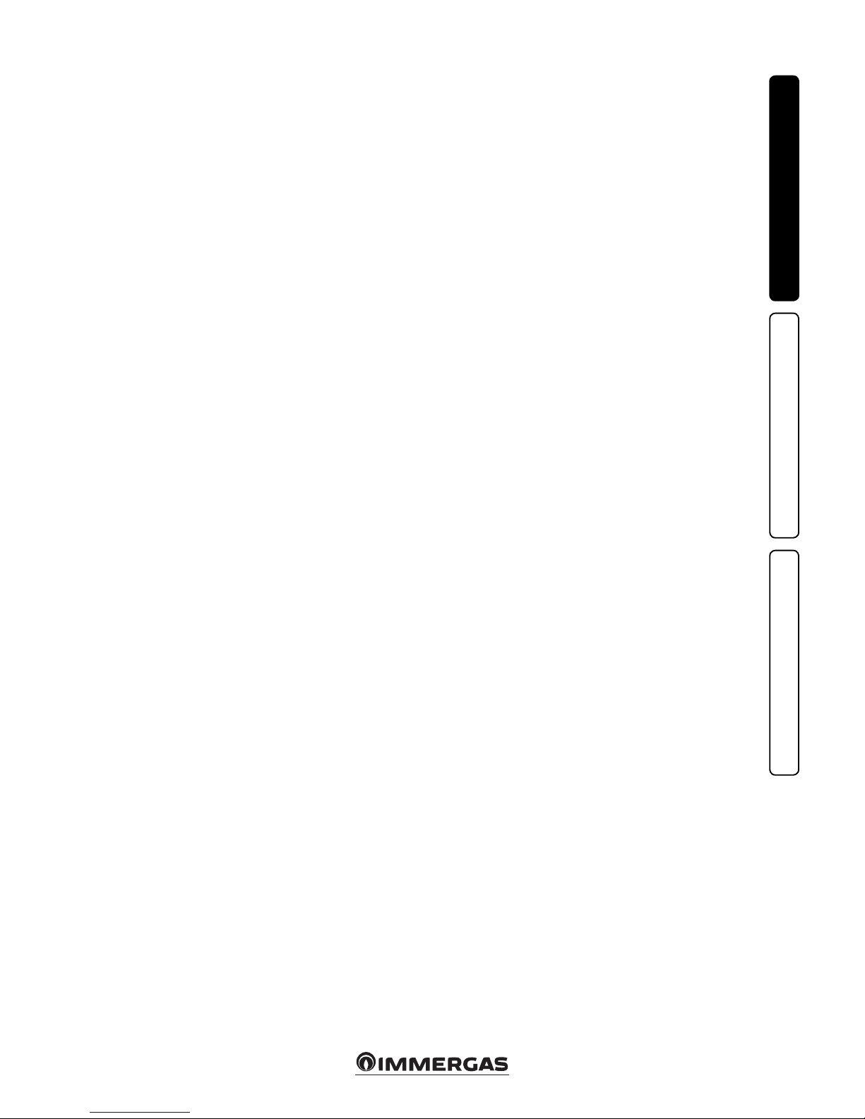
Vel. 9
Vel. 9
Vel. 6
Victrix Tera 28 1
A
B
C
D
Vel. 5
Vel. 9
Vel. 9
33
34
Victrix Tera 32 1
INSTALLERUSERMAINTENANCE TECHNICIAN
Total head available to the system.
Head (kPa)
A+B = Head available with by-pass closed
B = Head available with by-pass open
C+D = Power absorbed by the pump with by-pass open (dotted area)
D = Power absorbed by the pump with by-pass closed (dotted area)
Circulator pump absorbed power (W)
Flow rate (l/h)
A+B = Head available with by-pass closed
B = Head available with by-pass open
C+D = Power absorbed by the pump with by-pass open (dotted area)
D = Power absorbed by the pump with by-pass closed (dotted area)
Circulator pump absorbed power (W)
Flow rate (l/h)
Head (kPa)
Page 23
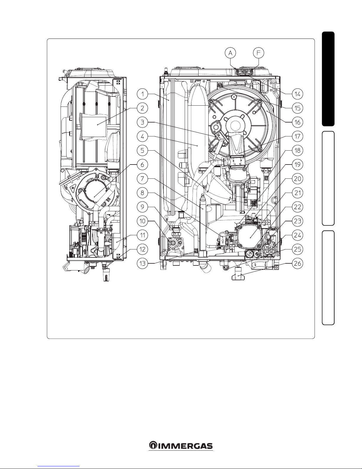
23
35
INSTALLERUSERMAINTENANCE TECHNICIAN
1.29 BOILER COMPONENTS.
Key:
1 - System expansion vessel
2 - Burner
3 - Ignition/detection electrode
4 - Air intake pipe
5 - Flow probe
6 - Fan
7 - Condensate drain trap
8 - Domestic hot water ow switch
9 - Gas nozzle
10 - Gas valve
11 - DHW heat exchanger
12 - System draining valve
13 - Domestic hot water probe
14 - Sample points (air A) - (ue gases F)
15 - Flue probe
16 - Condensation module
17 - Venturi
18 - Return probe
19 - System pressure switch
20 - Air vent valve
21 - Boiler pump
22 - 3 bar safety valve
23 - By-pass
24 - 3-way valve (motorised)
25 - Valve drain tting signal
26 - System lling valve
1.30 KITS AVAILABLE ON REQUEST.
• System cut-o valve kits with or without inspectionable lter (on request) e boiler is
designed for installation of system interception
cocks to be placed on ow and return pipes
of the connection assembly. is kit is very
useful for maintenance because it allows to
empty just the boiler without having to empty
the entire system. Moreover, the version with
lter preserves the functioning characteristics
of the boiler thanks to its inspectionable lter.
• Polyphosphate dispenser kit (on request). e
polyphosphate dispenser reduces the formation
of lime-scale and preserves the original heat
exchange and domestic hot water production
conditions. e boiler is prepared for application of the polyphosphate dispenser kit.
• Cover kit (on request). If installed outdoors in a
partially protected place with direct air intake,it
is compulsory to mount the appropriate top
protection cover for the correct functioning
of the boiler and to protect it from adverse
weather conditions.
• Cycloidal lter kit (on request). e magnetic
cycloidal filter is able to detect the ferrous
residues present in the system's water. anks
to the two cocks in the kit, it facilitates maintenance by cleaning the lter without having
to empty the circuit.
e above-mentioned kits are supplied complete
with instructions for assembly and use.
Page 24
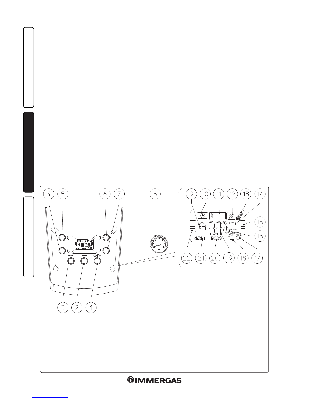
24
36
INSTALLERUSERMAINTENANCE TECHNICIAN
2
USE AND MAINTENANCE
INSTRUCTIONS.
2.1 CLEANING AND MAINTENANCE.
Attention: to preserve the boiler's integrity and
keep the safety features, performance and reliability which distinguish it unchanged over time,
maintenance operations must be carried out on a
yearly basis in compliance with that stated in the
“annual check and maintenance of the appliance”
section, in compliance with national, regional, or
local standards in force.
2.2 GENERAL WARNINGS.
Never expose the wall-mounted boiler to direct
vapours from a cooking surface.
Use of the boiler by unskilled persons or children
is strictly prohibited.
For safety purposes, check that the air intake/
ue exhaust terminals (if tted) are not blocked.
If temporary shutdown of the boiler is required,
proceed as follows:
a) drain the heating system if anti-freeze is not
used;
b) shut-o all electrical, water and gas supplies.
In the case of work or maintenance to structures
located in the vicinity of ducting or devices for
ue extraction and relative accessories, switch o
the appliance and on completion of operations
ensure that a qualied technician checks eciency of the ducting or other devices.
Never clean the appliance or connected parts
with easily ammable substances.
Never leave containers or ammable substances
in the same environment as the appliance.
• Attention: using any components that use
electrical power requires some fundamental
rules to be observed:
- do not touch the appliance with wet or moist
parts of the body; do not touch when barefoot;
- never pull electrical cables or leave the appliance exposed to atmospheric agents (rain,
sunlight, etc.);
- the appliance power cable must not be replaced by the user;
- in the event of damage to the cable, switch
off the appliance and contact exclusively
qualied sta for replacement;
- if the appliance is not to be used for a certain
period, disconnect the main power switch.
N.B.: the temperatures indicated by the display
have a tolerance of +/- 3°C due to environmental
conditions that cannot be attributed to the boiler.
At the end of its service life, the appliance must
not be disposed of like normal household waste
nor abandoned in the environment, but must
be removed by a professionally authorised
company. Contact the manufacturer for disposal
instructions.
2.3 CONTROL PANEL.
Key:
1 - O/Stand-by/Summer/Winter button
2 - Information buttons
3 - Reset Button
4 - Button to reduce the domestic hot water
temperature
5 - Button to increase the domestic hot
water temperature
6 - Button to increase the system water ow
temperature
7 - Button to decrease the system water ow
temperature
8 - Boiler manometer
9 - DHW production phase function active
10 - Boiler connected to remote control V2
(optional) or to other external devices
11 - Flame presence symbol and relative
output scale
12 - Operation with external temperature
probe active (optional)
13 - Solar function active
14 - Central heating room mode function
active
15 - Central heating temperature level
indicator
16 - Boiler in Stand-by mode
17 - Operation in winter mode
18 - Operation in summer mode
19 - Temperature indicator, boiler info and
error codes
20 - Not used on this model
21 - Blocked boiler, it needs to be
unblocked by pressing the “RESET”
button
22 - D.H.W. temperature level indicator
Page 25
25
INSTALLERUSERMAINTENANCE TECHNICIAN
2.4 USING THE BOILER.
Before ignition make sure the heating system
is lled with water and that the manometer (8)
indicates a pressure of 1 ÷ 1.2 bar.
- Open the gas cock upstream from the boiler.
- Press the button “ “ repeatedly to
cyclically switch from “stand-by” ( ) to
“summer” ( ) and “winter” ( ) mode.
• Summer ( ): in this mode the boiler functions only to produce the DHW, the temper-
ature is set via the buttons “ “ and the
relative temperature is shown on the display
via the indicator (19). Moreover, the temperature level that can be selected is shown on the
indicator (22).
• Winter ( ): in this mode the boiler works
both for producing domestic hot water and
for central heating. e DHW temperature is
always regulated via the buttons “ “, the
central heating temperature is regulated via the
buttons “ “ and the relative temperature
is shown on the display via the indicator (19).
Moreover, the temperature level that can be
selected is shown on the indicator (15).
From this moment the boiler functions automatically. With no demand for heat (central heating
or domestic hot water production) the boiler
goes to “standby” function, equivalent to the
boiler being powered without presence of ame.
Each time the burner ignites, the relative ame
present symbol is displayed (11) with relative
output scale.
• Operation with Comando Amico Remoto
remote control V2 (CARV2) (Optional). If the
CARV2 is connected, the ( ) symbol will
appear on the display. e boiler regulation parameters can be set via the CARV2 control panel
and the reset button (3) remains active on the
boiler control panel, along with the switch-o
button (1) (“o” mode only) and the display
where the functioning state is shown.
Caution: if the boiler is switched “o ” the
CARV2 will display the connection error symbol
“ERR>CM”, the CARV2 is however powered
constantly so as not to lose the stored programs.
• Solar operating mode ( ). is function
is activated automatically id the boiler detects
a probe on the DHW inlet (optional) or if the
“Solar ignition delay” parameter is more than
0 seconds.
During a withdrawal, if the outlet water is hot
enough or if there is “Solar ignition delay” time,
the boiler does not switch on, the D.H.W. with-
drawal symbol ( ) appears on the display
along with the ashing solar function symbol
( ).
When the water supplied by the solar system
is at a temperature lower than what is set, or
if the “Solar ignition delay” time has elapsed,
the boiler switches on. At this point, the solar
function symbol remains permanently on.
• Operation with optional external probe
( ). In the case of a system with optional
external probe, the boiler ow temperature
for room central heating is managed by the
external probe depending on the external
temperature measured (Par. 1.10). e ow
temperature can be modied by selecting the
functioning curve via the buttons “ “ (or
on the CARV2 control panel, if connected to the
boiler) selecting a value from “0 to 9”.
With external probe present, the relative
symbol (12) will appear on the display. In the
central heating mode, if the temperature of the
water contained in the system is sucient to
heat the radiators, the boiler can only function
with the activation of the pump.
• “Stand-by” mode. Press button “ “ re-
peatedly until the symbol ( ) appears. From
now on the boiler remains inactive and the
antifreeze function, pump anti-block function
and 3-way and signalling of any anomalies is
guaranteed.
N.B.: in these conditions the boiler is still
powered.
• “O” mode. By holding the button “ “
down for 8 seconds, the display switches-o
and the boiler is o completely. e safety
functions are not guaranteed in this mode.
N.B.: while not having functions active, in these
conditions the boiler must be considered still
live. is state is displayed by a “dot” lit in the
centre of the display.
• Display functioning. e display lights up
while the control panel is being used; aer
a set inactivity period, the brightness drops
until only the active symbols are displayed. e
lighting mode can be varied via parameter “t8”
in the P.C.B. programming menu.
Page 26

26
INSTALLERUSERMAINTENANCE TECHNICIAN
2.5 FAULT AND ANOMALY SIGNALS.
e Victrix Tera boiler reports any anomalies via
a code shown on the boiler display (19) according
to the following table:
Error
Code
Anomaly signalled Cause Boiler status / Solution
01 No ignition block
In the event of request of room central heating or domestic hot
water production, the boiler does not switch on within the preset
time. Upon appliance commissioning or aer extended downtime,
it may be necessary to eliminate the block.
Press the Reset button (1)
02
Safety thermostat
block (over-temperature)
During normal operation, if a fault causes excessive overheating
internally, the boiler goes into overheating block.
Press the Reset button (1)
03
Flue safety thermostat
block
During normal operation, if a fault causes excessive ue gas overheating, the boiler blocks
Press the Reset button (1)
04
Contacts resistance
block
e P.C.B. detects a fault on the gas valve supply. Check its connection.
(the anomaly is detected and displayed only in the event of a request).
Press the Reset button (1)
05 Flow probe anomaly e board detects an anomaly on the ow NTC probe. e boiler does not start (1)
06
Domestic hot water
probe anomaly
e board detects an anomaly on the domestic hot water NTC probe.
In this case the antifreeze function is also inhibited
In this case the boiler continues to produce
domestic hot water but not with optimal
performance (1)
08 Maximum N° of resets Number of allowed resets that have already performed.
Attention: the fault may be reset up to
5 times consecutively, after which the
function in inhibited for at least one hour.
One attempt is gained every hour for a
maximum of 5 attempts. By switching the
appliance on and o again, the 5 attempts
are re-acquired.
10
Insucient system
pressure
Water pressure inside the central heating circuit that is sucient to
guarantee the correct operation of the boiler is not detected.
Check on the boiler pressure gauge (1) that
the system pressure is between 1÷1.2 bar
and restore the correct pressure if necessary.
15 Conguration error
If the board detects an anomaly or incongruity on the electric wiring,
the boiler will not start.
If normal conditions are restored the boiler
restarts without having to be reset. Check
that the boiler is congured correctly (1)
16 Fan anomaly is occurs if the fan has a mechanical or electrical fault. Press the Reset button (1)
20 Parasite ame block
is occurs in the event of a leak on the detection circuit or anomaly
in the ame control unit.
Press the Reset button (1)
23 Return probe anomaly e board detects an anomaly on the return NTC probe e boiler does not start (1)
24
Push button control
panel anomaly
e board detects an anomaly on the pushbutton panel.
If normal conditions are restored the boiler restarts without having to be reset (1).
27 Insucient circulation
is occurs if there is overheating in the boiler due to insucient water
circulating in the primary circuit; the causes can be:
- low system circulation; check that no shut-o devices are closed on
the heating circuit and that the system is free of air (deaerated);
- circulating pump blocked; free the circulating pump.
Press the Reset button (1).
29 Flue probe anomaly e board detects an anomaly on the ue gas probe e boiler does not start (1)
31
Loss of remote control
communication.
This occurs if an incompatible remote control is connected, or if
communication between the boiler and the remote control is lost
Disconnect and reconnect the power to the
boiler. If the Remote Control is still not
detected on re-starting, the boiler will
switch to local operating mode, i.e. using
the controls on the control panel. In this
case the "Central Heating" (1) function
cannot be activated.
37
Low power supply
voltage
This occurs when the power supply voltage is lower than the allowed
limits for the correct boiler operation.
If normal conditions are restored the boiler
restarts without having to be reset (1)
38 Loss of ame signal
This occurs when the boiler is ignited correctly and the burner
flame switches off unexpectedly; a new attempt at ignition is
performed and if normal conditions are restored, the boiler does
not have to be reset.
If normal conditions are restored the boiler
restarts without having to be reset (1) (2)
43
Block due to loss of
ame signal
is occurs if the ''Flame signal loss'' error occurs many times in a
row within a preset period (38).
Press the Reset button, before restarting,
the boiler will run a post-ventilation
cycle. (1)
(1) If the block or anomaly persists, contact an authorised company (e.g. Immergas Technical Aer-Sales Service).
(2) The anomaly can only be verified in the list of errors in the “Information” menu
Page 27
27
INSTALLERUSERMAINTENANCE TECHNICIAN
Error
Code
Anomaly signalled Cause Boiler status / Solution
45
High T
e boiler detects a sudden, unexpected increase in the ΔT between
the ow probe and the system return probe.
e power of the burner is limited to prevent damage to the condensation module
and once the right ΔT is restored, the boiler
resumes regular operation. Make sure there
is water circulating in the boiler, that the
pump is congured according to system
requirements and that the return probe
works properly. (1) (2)
47
Burner power limitation
Should ue high temperature be detected, the boiler reduces power
supplied so as not to damage it.
(1)
51
CAR Wireless communication failure
If there is no communication between the boiler and Wireless version
CAR, an anomaly is signalled. From this moment, it is only possible
to control the system by means of the control panel of the boiler itself.
Check operation of the Wireless CAR,
check the battery charge (refer to the relative
instructions booklet).
60
Anomaly pump
blocked
e pump is stopped due to one of the following causes:
Impeller blocked, electrical fault.
Try to unblock the pump as described in
the relative section. If normal conditions are
restored the boiler restarts without having
to be reset (1)
61 Air in circulator pump Air is detected inside the pump; the pump cannot work.
Vent the pump and the central heating circuit. If normal conditions are restored the
boiler restarts without having to be reset (1)
70
Return/ow probe
exchange
In case of an incorrect boiler wiring connection the error is detected e boiler does not start (1)
75
Return and/or ow
probe malfunction
Possible failure of one or both system return and ow probes e boiler does not start (1)
76
Return and/or flow
probes temperature
dri
A malfunction of one or both system return and ow probes is
detected
e boiler does not start (1)
(1) If the block or anomaly persists, contact an authorised company (e.g. Immergas Technical Aer-Sales Service).
(2) The anomaly can only be verified in the list of errors in the “Information” menu
Page 28

28
INSTALLERUSERMAINTENANCE TECHNICIAN
2.6 INFORMATION MENU.
By pressing the button “ “, the “Information
menu” is activated for at least 1 second, displaying some boiler operating parameters.
To scroll through the various parameters, press
the buttons “DHW regulation” “ “.
With the menu active on the indicator (19) the parameter via the letter “d”
plus the number of the parameter that is
being displayed will alternately show.
To view the parameter value, select it by pressing
the button
.
Press “
” or wait 15 minutes to go back to
the previous screen or exit the menu.
2.7 BOILER SHUTDOWN
Switch the boiler o by putting it in “o ” mode,
disconnect the onmipolar switch outside of the
boiler and close the gas cock upstream from the
appliance. Never leave the boiler switched on if
le unused for prolonged periods.
2.8 RESTORE CENTRAL HEATING
SYSTEM PRESSURE
Periodically check the system water pressure.
e boiler pressure gauge should read a value of
between 1 and 1.2 bar.
If pressure falls below 1 bar (with the circuit cold),
restore normal pressure via the cock located at the
bottom of the boiler (Part. 1 Fig. 6).
N.B.: close the valve aer the operation.
If pressure values reach around 3 bar the safety
valve may be activated.
In this case, remove water from a radiator air
vent valve until a pressure of 1 bar is achieved,
or ask for assistance from professionally qualied
personnel.
In the event of frequent pressure drops, contact
qualified staff for assistance to eliminate the
possible system leakage.
2.9 DRAINING THE SYSTEM.
To drain the boiler, use the special draining
valve (Fig. 6).
Before draining, ensure that the lling cock is
closed.
2.10 ANTIFREEZE PROTECTION.
The “Victrix Tera” series boiler features an
antifreeze function that lights the burner automatically when the temperature falls below
4°C (standard protection down to min. temperature of -5°C). All information relative to the
anti-freeze protection is stated in Par. 1.3. In
order to guarantee the integrity of the appliance
and the domestic hot water heating system in
zones where the temperature falls below zero,
we recommend the central heating system is
protected using anti-freeze liquid and installation
of the Immergas Anti-freeze Kit in the boiler. In
the case of prolonged inactivity (second case),
we also recommend that:
- the electric power supply is disconnected;
- the heating circuit and boiler domestic water
circuit must be drained. In systems that are
drained frequently, lling must be carried out
with suitably treated water to eliminate hardness that can cause lime-scale.
2.11 CASE CLEANING.
Use damp cloths and neutral detergent to clean
the boiler casing. Never use abrasive or powder
detergents.
2.12 DECOMMISSIONING.
In the event of permanent shutdown of the boiler,
contact professional sta for the procedures and
ensure that the electrical, water and gas supply
lines are shut o and disconnected.
Id
Parameter
Description
d 0.0 Not used
d 0.1 Displays the ame signal (uA)
d 0.2 Displays the primary exchanger output instant heating ow temperature
d 0.3 Displays the instant output temperature from the DHW exchanger
d 0.4 Displays the values set for central heating set
d 0.5 Displays the values set for DHW set
d 0.6
Displays the external environment temperature (if optional external probe present)
If the temperature is below zero, the value is displayed ashing.
d 0.7 Displays the temperature of the inlet DHW (with optional DHW inlet probe present)
d 0.8 Displays the system return water temperature
d 0.9
Displays the list of the last eight anomalies.
(to scroll the list press the “central heating temperature regulation” buttons (6 and 7))
d 1.0
Anomaly list reset. Once “d 1.0” is displayed, press the Reset button for at least 3 seconds; deletion is conrmed via the “88” symbols
ashing for two seconds
d 1.1 Not used
d 1.2 Displays the pump operating speed
d 1.3 Not used
d 1.4 Displays the pump ow rate (lh/100)
d 1.5 Displays the fan operating speed (rpm/100)
d 1.6 Displays the temperature read on the ue probe
d 1.7 Displays the calculated ow temperature
d 1.8 At the end of the screed heater function, displays for how many hours the ow temperature remained at “Top set”
d 1.9 Toggles between the safety soware version and the functional soware version
d 2.0 Displays the ow temperature of zone two (optional)
d 2.1 Displays the ow temperature of zone three (optional)
d 2.2 Not used
Page 29

29
37
INSTALLERUSERMAINTENANCE TECHNICIAN
3
BOILER STARTUP INI
TIAL CHECK.
To commission the boiler:
- ensure that the type of gas used corresponds to
boiler settings;
- check connection to a 230V-50Hz power
mains, correct L-N polarity and the earthing
connection;
- make sure the central heating system is lled
with water and that the boiler manometer
indicates a pressure of 1÷1.2 bar.
- switch the boiler on and ensure correct ignition;
- check the proper calibration of the number of
fan revolutions;
- check the CO2 in the combustion products at
maximum and minimum ow rate;
- check activation of the safety device in the event
of no gas, as well as the relative activation time;
- check the intervention of the main switch located upstream of the boiler and in the boiler;
- check that the intake and/or exhaust terminals
are not blocked;
- ensure activation of all adjustment devices;
- seal the gas ow rate regulation devices (if
settings are modied);
- ensure production of domestic hot water;
- ensure sealing eciency of water circuits;
- check ventilation and/or aeration of the installation room where provided.
Even if just one single safety check provides a
negative result, do not commission the system.
3.1 BOILER HYDRAULIC DIAGRAM.
Key:
1 - Gas valve
2 - Domestic hot water ow switch
3 - Gas nozzle
4 - Flow limiter
5 - Domestic hot water probe
6 - Condensate drain trap
7 - System lling valve
8 - DHW heat exchanger
9 - System expansion vessel
10 - Positive (+) pressure point
11 - Venturi
12 - Flow probe
13 - Ignition/detection electrodes
14 - Air intake pipe
15 - Flue probe
16 - Flue sample point
17 - Air sample point
18 - Burner
19 - Return probe
20 - Fan
21 - Air vent valve
22 - Boiler pump
23 - Absolute pressure switch
24 - 3-way valve (motorised)
25 - By-pass
26 - System draining valve
27 - 3 bar safety valve
28 - 3 bar safety valve drain tting signal
G - Gas supply
AC - Domestic hot water outlet
AF - Domestic hot water inlet
SC - Condensate drain
M - System ow
R - System return
Page 30

30
38
INSTALLERUSERMAINTENANCE TECHNICIAN
3.2 WIRING DIAGRAM.
Colour code key:
BK - Black
BL - Blue
BR - Brown
G - Green
DY - Grey
OR - Orange
P - Purple
PK - Pink
R - Red
W - White
Y - Yellow
Y/G - Yellow/Green
Key:
B1 - Flow probe
B2 - Domestic hot water probe
B4 - External probe (optional)
B5 - Return probe
B9 - DHW inlet probe (optional)
B10 - Flue probe
CARV2 - Comando Amico Remoto
V2
remote
control (optional)
E3 - Ignition and detection electrode
M1 - Boiler pump
M20 - Fan
M30 - ree-way motor stepper
S4 - Domestic hot water ow switch
S5 - System pressure switch
S20 - Room thermostat (optional)
T2 - Ignition transformer
X40 - Room thermostat jumper
Y1 - Gas valve
Comando Amico RemotoV2: the boiler is prepared for the application of the Comando Amico
Remoto remote control V2 (CARV2), which must
be connected to clamps 44/40 and 41 of the
terminal board (located in the boiler control
panel) respecting the polarity and eliminating
jumper X40.
Room thermostat: the boiler is prepared for the
application of the room thermostat (S20), which
must be connected to clamps 44/40 - 41 of the
terminal board (located in the boiler control
panel) eliminating jumper X40.
230 Vac 50Hz
supply voltage
Page 31

31
+
+
3
12
2
1
P1
P3
39
INSTALLERUSERMAINTENANCE TECHNICIAN
3.3 TROUBLESHOOTING
N.B.: maintenance interventions must be carried
out by an authorised company (e.g. Immergas
Aer-Sales Technical Assistance Service).
- Smell of gas. Caused by leakage from gas circuit
pipelines. Check sealing eciency of gas intake
circuit.
- Repeated ignition blocks. It can be caused by
no gas, check the presence of pressure in the
network and that the gas adduction cock is
open. Incorrect adjustment of the gas cock,
check the correct calibration of the gas valve.
- Irregular combustion or noisiness. It may be
caused by: a dirty burner, incorrect combustion
parameters, intake-exhaust terminal not correctly installed. Clean the above components
and ensure correct installation of the terminal,
check correct setting of the gas valve (O-Set
setting) and correct percentage of CO2 in ue
gas.
- Frequent interventions of the safety thermostat
function (delegated to ow probe and system
return probe). It can depend on the lack of
water in the boiler, little water circulation in the
system or blocked pump. Check on the pressure
gauge that the system pressure is within established limits. Check that the radiator valves
are not closed and also the functionality of the
pump.
- Siphon blocked. is may be caused by dirt or
combustion products deposited inside. Check,
by means of the condensate drain cap, that
there are no residues of material blocking the
ow of condensate.
- Heat exchanger blocked. is may be caused
by the drain trap being blocked. Check, by
means of the condensate drain cap, that there
are no residues of material blocking the ow of
condensate.
- Noise due to air in the system. Check opening
of the special air vent valve cap (Fig. 6). Make
sure the system pressure and expansion vessel
pre-charge values are within the set limits; e
factory-set pressure values of the expansion
vessel must be 1.0 bar, the value of system
pressure must be between 1 and 1.2 bar.
3.4 CONVERTING THE BOILER TO
OTHER TYPES OF GAS.
If the boiler has to be converted to a dierent
gas type to that specied on the data nameplate,
request the relative conversion kit for quick and
easy conversion.
e gas conversion operation must be carried
out by an authorised company (e.g. Immergas
Aer-Sales Technical Assistance Service).
To convert to another type of gas the following
operations are required:
- remove the voltage from the appliance;
- replace the nozzle located on the gas valve and
gas/air mixing sleeve (Part. 9 Fig. 35), taking
care to disconnect the appliance during this
operation;
- apply voltage to the appliance;
- calibrate the number of fan revolutions (Parag.
3.5);
- adjust the correct air/gas ratio (Parag. 3.6);
- seal the gas ow rate devices (if adjusted);
- after completing the conversion, apply the
sticker, contained in the conversion kit, on the
data plate in the area relating to the type of gas.
ese adjustments must be made with reference
to the type of gas used, following that given in
the table (Par. 3.21).
3.5 CALIBRATION OF NUMBER OF FAN
REVS.
Attention: verication and calibration is neces-
sary, in the case of transformation to other types
of gas, in the extraordinary maintenance phase
with replacement of the PCB air/gas circuit components or in the case of installations with ue
extraction systems, with horizontal concentric
pipe measuring more than 1 metre.
e boiler heat output is correlated to the length
of the air intake and ue exhaust pipes. is
decreases with the increase of pipe length. e
boiler leaves the factory adjusted for minimum
pipe length (1m coaxial).
- activate ue test (Parag. 3.12);
- detect the ue signal ∆P (Ref. 16 and 17 Fig.
37);
- compare the signal ∆P and, if necessary,
correct the S1 operating parameters with the
following table:
Victrix Tera 28 1
∆P > 200 Pa
G20 S1 = 126 (6300 rpm)
G31 S1 = 121 (6050 rpm)
Victrix Tera 32 1
∆P > 200 Pa
G20 S1 = 134 (6700 rpm)
G31 S1 = 127 (6350 rpm)
3.6 ADJUSTMENT OF THE AIRGAS
RAT IO.
Attention: the CO2 verication operations must
be carried out with the casing mounted, while the
gas valve calibration operations must be carried
out with the casing open and disconnecting the
boiler from the power supply.
Calibration of the CO2 at minimum output
Enter the chimney sweep mode without withdrawing DHW and set the output to minimum
(0%). To have an exact value of CO2 the technician must insert the sampling probe to the
bottom of the sample point, then check that the
CO2 value is that specied in the table, otherwise adjust the screw (Part. 3 Fig. 39) (O-Set
adjuster). To increase the CO2 value, turn the
adjustment screw (3) in a clockwise direction
and vice versa to decrease it.
Calibration of the CO2 at maximum output
When you nish the minimum CO2 adjustment,
while maintaining the chimney sweep function
active, set the output to maximum (99%). To
have an exact value of CO2 the technician must
insert the sampling probe to the bottom of the
sample point, then check that the CO2 value is
that specied in the table, otherwise adjust the
screw (Part. 12 Fig. 39) (gas ow rate regulator).
To increase the CO2 value, turn the adjustment
screw (12) in a clockwise direction and vice versa
to decrease it.
At every adjustment variation on the screw 12 it
is necessary to wait for the boiler to stabilise itself
at the value set (about 30 sec.).
Key:
1 - Gas valve inlet pressure
point
2 - Gas valve outlet pressure
point
3 - O/Set adjustment screw
12 - Outlet gas ow rate
adjuster
42 Gas Valve
Page 32
32
INSTALLERUSERMAINTENANCE TECHNICIAN
3.7 CHECKS FOLLOWING
CONVERSION TO ANOTHER TYPE
OF GAS.
Aer making sure that conversion was carried
out with a nozzle of suitable diameter for the
type of gas used and the settings are made at the
correct pressure, check that the burner ame is
not too high or low and is stable (does not detach
from burner);
N.B.: all boiler adjustment operations must be
carried out by a qualied technician (e.g. Immergas Aer-Sales Assistance).
Victrix Tera 28 1
CO2 at maximum
output
CO2 at minimum
output
G 20
9,70 %
+ 0,50 / - 0,20
8,80 %
+ 0,20 / - 0,30
G 31 11,40 % ± 0,30 10,60 % ± 0,20
Victrix Tera 32 1
CO2 at maximum
output
CO2 at minimum
output
G 20 9,50 % ± 0,20
8,60 %
+ 0,20 / - 0,30
G 31
11,20 %
+ 0,20 / - 0,40
10,00 %
+ 0,40 / - 0,20
Page 33
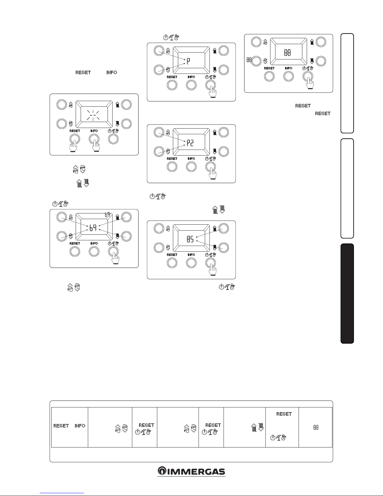
33
INSTALLERUSERMAINTENANCE TECHNICIAN
3.8 PROGRAMMING THE P.C.B.
e boiler is prepared for possible programming of
several operation parameters. By modifying these
parameters as described below, the boiler can be
adapted according to specic needs.
To access the programming phase, press and hold
the buttons “ ” and “ ” for more
than 5 seconds, the display shows two dashes
“--” ashing and you must enter the password
to access the programming menus.
40
To enter the rst digit use the buttons to adjust
the DHW “ ”, to enter the second digit
use the buttons to adjust the central heating
temperature “ ”.
To confirm the password ( ) and access
the menu, press the operating mode button
“ ”.
41
Once in the menu, you can cyclically scroll the
four submenus (P, t, A, S) by pressing the DHW
buttons “ ”, to access the menu press the
46
+
> 5’’
Menu
“P”
“t”
“A”
“S”
←
→
P0 ÷ P5
t0 ÷ t9
A0 ÷ A6
S0 ÷ S2
←
→
Parameter
value
←
(Without mem-
orising)
> 1’’
(Memorise)
“ ”
button “ ”.
42
e rst digit of the central indicator (19) shows
the family of the parameter, while the second
digit shows its number.
43
Pressing the mode of operation button
“ ” displays the value of the selected
parameter and by pressing the buttons to adjust
the central heating temperature “ ” you
can adjust its value.
44
Press the mode of operation button “
” for more than 1 second to store the parameter
value; conrmation is given by the word “ ”
which appears for 2 seconds.
45
If you want to exit a parameter without changing
its value, press the button “ ”.
Wait for 15 minutes or press the “ ”
button to exit programming mode.
Programming phase sequence.
Page 34
34
INSTALLERUSERMAINTENANCE TECHNICIAN
Id
Parameter
Parameter Description Range Default
Customised
value
P0
Max DHW
output
Denes the maximum heat output percentage of the boiler during the D.H.W.
phase compared to the maximum heat output available
0 - 100 % 100 %
P1 Min CH output Denes in percentage the minimum output in central heating mode 0 - P2 0 %
P2 Max CH output
Denes the maximum heat output percentage of the boiler during the central
heating mode compared to the maximum heat output available
0 - 100 %
Victrix Tera
28 1
G20 = 85
G31 = 82
Victrix Tera
32 1
G20 = 85
G31 = 85
P3 - Not available for this model -. -
P4
Pump function-
ing
e pump can function in two ways.
0 intermittent: in winter "mode" the circulator is managed by the room
thermostat or by the remote control
1 continuous: in "winter" mode the circulator is always powered and is
therefore always in operation
0 - 1 0
P5
External probe
correction
If the reading of the external probe is not correct it is possible to correct it
in order to compensate any environmental factors.
-9 ÷ 9 K 0
P6 - Not available for this model - -
P7 - Not available for this model - -
Id
Parameter
Parameter Description Range Default
Customised
value
t0
Central heating
set point minimum temper-
ature
Denes the minimum ow temperature. 20 ÷ 50 °C 25
t1
Central heating
set point maximum temper-
ature
Denes the maximum ow temperature.
(t0+5) ÷
85 °C
85
t2
Solar delay
timing
e boiler is set to switch-on immediately aer a request. for DHW In the
case of coupling with a solar storage tank positioned upstream from the boiler,
it is possible to compensate the distance between the storage tank and the
boiler in order to allow the water to reach the boiler. Set the time necessary
to verify that the water is hot enough (see par. Solar panels coupling)
0 - 30
seconds
2
t3
Domestic hot
water priority
timing
In winter mode the boiler, at the end of a domestic hot water request, is
ready to switch to central heating mode if there is an active request. Timing
sets a time period in which the boiler waits before changing the operating
mode, in order to quickly and comfortably satisfy an additional request for
domestic hot water.
0 - 100
seconds
(step 10 sec)
2
t4
Central heating
ignitions timer
e boiler has electronic timing, which prevents the burner from igniting
too oen in central heating mode
0 - 600
seconds
(step 10 sec)
18
t5
Central heating
ramp timer
In the heating stage, the boiler performs an ignition ramp in order to reach
the maximum output set
0 - 840
seconds
(step 10 sec)
18
t6
CH ignition delay from TA and
CR request
e boiler is set to switch-on immediately aer a request. In the event of
particular systems (e.g. area systems with motorised thermostatic valves
etc.) it may be necessary to delay ignition
0 - 600
seconds
(step 10 sec)
0
t7 Display lighting
Establishes the display lighting mode.
0 : the display lights up during use and lowers aer 15 seconds of inactivity.
In the case of anomaly the display ashes.
1 : display lighting o.
2 : the display is always lit up.
0 - 2 0
t8 Display
Establishes what the indicator displays 14 (Fig. 36).
"Summer" mode:
0: the indicator is always o
1: pump active displays the ow temperature,
pump o the indicator is o
"Winter" mode:
0: always displays the value set on the CH selector
1: pump active displays the ow temperature,
pump o always displays the value set on the CH selector
0 - 1 1
Page 35
35
INSTALLERUSERMAINTENANCE TECHNICIAN
t9
Flow o tempera-
ture increase
Increases the ow o temperature at ignition only in the rst 60 seconds.
Aer the ame is detected, the temperature is increased by t9
0 - 15 0
Id
Parameter
Parameter Description Range Default
Customised
value
A0 Hydraulic model Denes the type of hydraulics in the boiler (0 = instant; 1 = storage tank) 0 ÷ 1 0
A1
Maximum pump
speed
Denes the maximum operating speed of the circulator
(If A1 = A2 circulator operating at set speed)
A2 - 9 9
A2
Minimum pump
speed
Denes the minimum operating speed of the circulator 1 - A1
Victrix Tera
28 1
6
Victrix Tera
32 1
5
A3
Pump operating
mode
Sets the pump operating mode
- DELTA T = 0: proportional head (see Parag. 1.28)
- DELTA T = 5 ÷ 25 K: ∆T constant (see Parag. 1.28)
0 ÷ 25 15
A4
Storage tank ow
oset
Establishes the temperature to be added to the DHW set-point to calculate
the ow set to heat the storage tank (only useful with a coupled storage tank
and parameter A0=1).
5 ÷ 50 °C 25
A5
Storage tank
activation oset
Temperature value to be subtracted from the DHW set-point to calculate the
boiler ignition to heat the storage tank (only useful with a coupled storage
tank and parameter A0=1).
0 ÷ 15 °C 3
A6 DHW thermostat
Establishes the switch-o method in DHW mode.
0 Fixed: the switch-o temperature is xed at the maximum value regardless
of the value set on the control panel.
1 Correlated: the boiler switches o according to the temperature set.
0 ÷ 1 0
Victrix Tera 28 1
Id
Parameter
Parameter Description Range Default
Customised
value
S0
DHW minimum
no. of fan revs
Denes the operating speed of the fan at minimum DHW output
20 ÷ 60
(in RPM
x 50)
28 (G20)
27 (G31)
S1
DHW maximum
no. of fan revs
Denes the operating speed of the fan at maximum DHW output
S0 ÷ 140
(in RPM
x 50)
121 (G20)
115 (G31)
S2
Ignition phase
no. of fan revs
Denes the operating speed of the fan during the ignition phase
40 ÷ 80
(in RPM
x 50)
56 (G20)
56 (G31)
Victrix Tera 32 1
Id
Parameter
Parameter Description Range Default
Customised
value
S0
DHW minimum
no. of fan revs
Denes the operating speed of the fan at minimum DHW output
20 ÷ 60
(in RPM
x 50)
30 (G20)
28 (G31)
S1
DHW maximum
no. of fan revs
Denes the operating speed of the fan at maximum DHW output
S0 ÷ 140
(in RPM
x 50)
128 (G20)
121 (G31)
S2
Ignition phase
no. of fan revs
Denes the operating speed of the fan during the ignition phase
40 ÷ 80
(in RPM
x 50)
56 (G20)
56 (G31)
Page 36
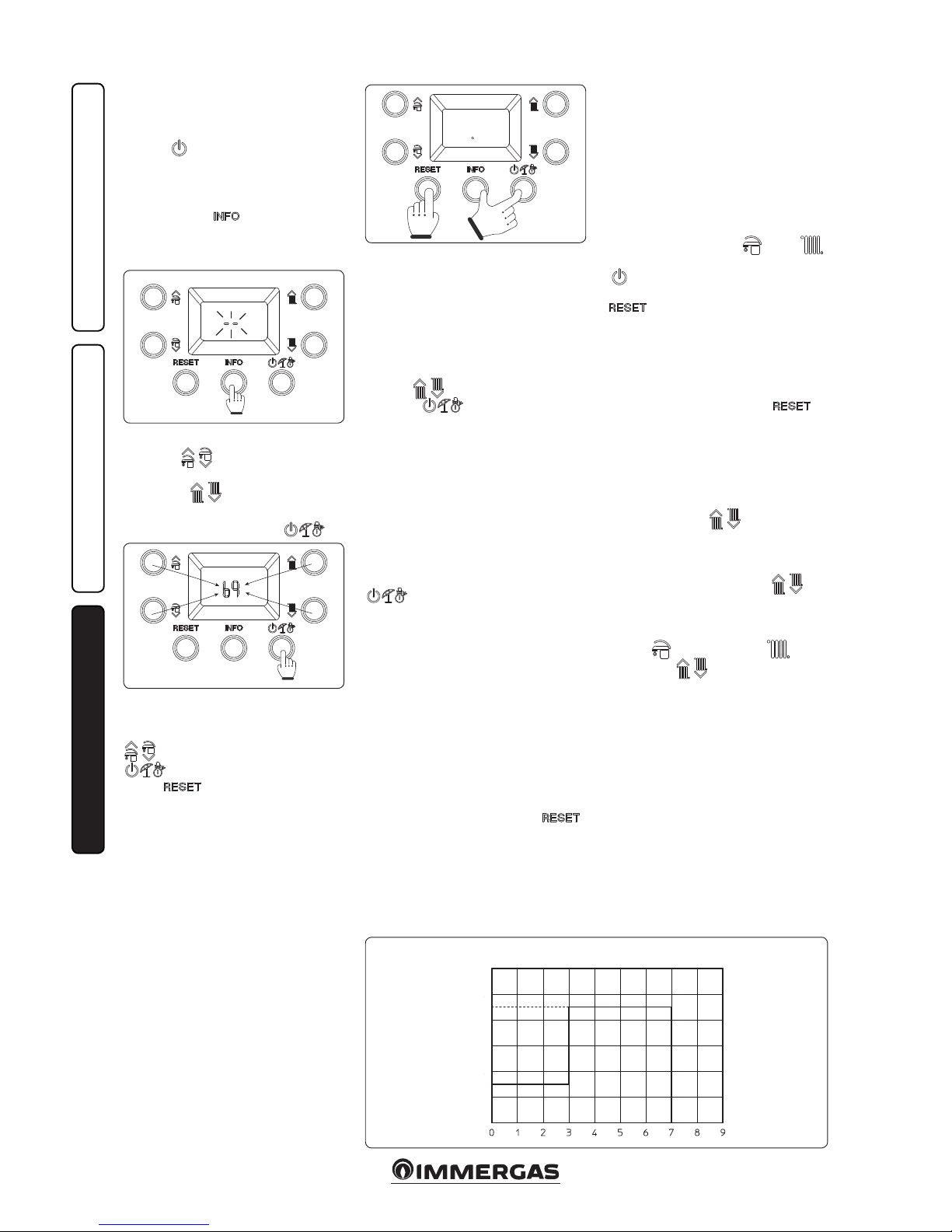
36
47
UPPER
SET
DAYS
TM (°C)
LOWER
SET
INSTALLERUSERMAINTENANCE TECHNICIAN
3.9 PASSWORDPROTECTED SPECIAL
FUNCTIONS.
Attention: the boiler is equipped with some special
functions, access to which is granted if this is in
stand-by ( ) .
IMPORTANT NOTE: if the boiler is connect-
ed to the CARV2 the “stand-by” function can
only be activated via the remote control panel.
Press and hold the “ ” button for more t han
5 seconds. e display will show two dashes “--”
ashing. Now enter the password to access the
programming menus.
48
To enter the rst digit use the buttons to adjust
the DHW “ ”, to enter the second digit
use the buttons to adjust the central heating
temperature “ ”.
To conrm the password and access the menu,
press the operating mode button “ ”.
49
Once the menu has been accessed, it is possible
to cyclically scroll the three available functions
(dl, MA, FU) by pressing the DHW buttons “
”, to access the menu press the button “
” to exit wait 15 minutes or press the
button “ ”.
3.10 SCREED HEATER FUNCTION.
e boiler is equipped with a function to perform
the thermal shock on new radiant panel systems,
as required by the applicable standard.
Attention: contact the manufacturer of the radiant panels for the thermal shock characteristics
and its correct execution.
N.B.: to be able to activate the function there
must be no remote control connected, while
in case of system divided into zones it must
be properly connected, both hydraulically and
electrically.
e function is activated from boiler in OFF by
pressing and holding the buttons “Reset”, “Info”
and “Stand-by” for more tan 5 seconds.
50
e function lasts in total 7 days, 3 days at the
lower temperature set and 4 days at the higher
temperature set (Fig. 50).
Aer activating the function, the lower set (range
20 ÷ 45 °C default = 25 °C) and the higher set
(range 25 ÷ 55 °C default = 45 °C) appear in
sequence.
The temperature is selected by means of the
buttons “ ” and conrmed by pressing
the button “ ”.
e display now shows the countdown of days
alternated with the current ow temperature,
as well as the normal operating symbols of the
boiler.
In case of failure or lack of supply voltage, the
function is suspended and will resume when the
normal operating conditions are reset from the
point where it was interrupted.
When the time expires, the boiler automatically
goes back to “Stand-by” mode, the function
can also be stopped by pressing the button “
”.
3.11 AUTOMATIC VENT FUNCTION
DL.
In the case of new central heating systems and
in particular mode for oor systems, it is very
important that deaeration is performed correctly.
e function consists of the cyclic activation of
the pump (100 s ON, 20 s OFF) and the 3-way
valve (120 s D.H.W., 120 s C.H.).
e function is activated by accessing the special
“dl” function as described in Paragraph 3.9.
e function lasts for 16.5 hours and it can be
stopped by simply pressing the button “ ”.
Activation of the function is signalled by the
countdown shown on the indicator (20).
3.12 FLUE INSTALLATION FU.
To activate the “Flue” function access the special
functions as described in Paragraph 3.9 and
select the “FU” function.
Attention: Before performing the test, ensure
that the condensate drain trap has been lled
correctly and check that there are no obstructions
in the air intake circuit and ue exhaust.
Using this function activates the fan at a xed
speed (6000 rpm) for 15 minutes.
In this phase the symbols ( ) and (
) are displayed flashing, while the symbol
( ) is displayed permanently on, the function
can be stopped by simply pressing the button “
”.
3.13 MAINTENANCE FUNCTION MA.
Using this function you can activate some operating devices of the boiler without starting it,
thus verifying the functionality.
e function is active for 15 minutes and it can
be stopped by pressing the button “ ”.
To activate the “Maintenance” function access
the special functions as described in Paragraph
3.9 and select the “MA” function.
e following loads can be activated within this
function:
- Fan (Fn): the fan is brought to ignition speed.
Using the buttons “ ” you can increase
or decrease the fan speed.
- Circulator (Pu): the circulator is brought to
maximum speed, the relative speed is shown
on the display, using the buttons “ ” you
can increase or decrease the circulator speed.
- ree-way (3d): the symbol is shown on the
display according to the position of the valve,
DHW ( ) or central heating ( ), using
the buttons “ ” you can change the valve
position, taking care to wait for the completion
of passage between statuses.
- Congurable relay (rl): if the congurable relay
is present on the boiler P.C.B., it is activated.
Page 37
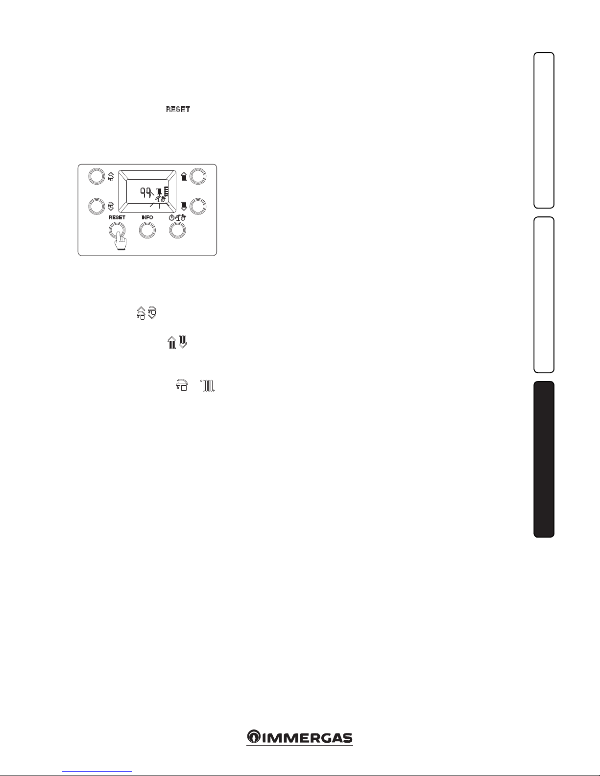
37
INSTALLERUSERMAINTENANCE TECHNICIAN
3.14 "CHIMNEY SWEEP FUNCTION".
When activated, this function forces the boiler
to variable output for 15 minutes.
In this state all adjustments are excluded and
only the safety thermostat and the limit thermostat remain active. To activate the chimney
sweep function, press the “ ” button
until activation of the function in the absence
of DHW requests.
Its activation on the boiler display is conrmed
by the indicators ashing at the same time (17
and 18 Fig. 36).
51
is function allows the technician to check the
combustion parameters.
Once the function is activated, it is possible to
select whether to make the chick in CH status
or DHW status by opening any hot water cock.
Using the buttons “ ” you can select the
power level between “0%” - Max CH output
(P2) - Max DHW output (P0).
While by using the buttons “ ” you can
select the power from 0% to max DHW output
(P0), with intervals of 1%.
e central heating or DHW operating mode is
displayed by the relative symbols or .
Aer the checks, deactivate the function switching the boiler o and then on again.
3.15 SOLAR PANELS COUPLING
FUNCTION.
The boiler is prepared to receive pre-heated
water from a system of solar panels up to a
maximum temperature of 65°C. In any case, it
is always necessary to install a mixing valve on
the hydraulic circuit upstream of the boiler, on
the cold water inlet.
To optimise the operation,where the probe is
not already tted on the boiler, the solar inlet
probe kit is available on request (see wiring
diagram Fig. 38):
if there is no probe kit, it is advisable to set
parameter A6 (DHW thermostat) at “1”;
otherwise, where the kit is installed or the probe
is already present in the boiler, parameter A6
must be le at “0”. is kit allows connecting
a probe on the domestic cold water inlet pipe
of the boiler to prevent unnecessary ignitions
in systems with water heating through solar
systems or alternative sources. e boiler will
not turn on if the inlet water is suciently hot.
In both conditions (probe present or not), we
recommend setting parameter t3 (solar delay
timing) at a time sucient to let the water inside
the D.H.W. circuit upstream of the boiler drain.
e greater the distance from the storage tank,
the longer wait time will have to be set.
With these adjustments made, when a domestic
withdrawal is requested, once the time set on
parameter “t3” has passed, if the water entering
the boiler is at a temperature that is equal or
greater to that set, the boiler will not turn on.
Note: in order for the boiler to work properly, the
temperature selected on the mixing valve must
be 5°C greater than the temperature selected on
the boiler control panel.
3.16 PUMP ANTIBLOCK FUNCTION.
e boiler has a function that starts the pump at
least once every 24 hours for the duration of 30
seconds in order to reduce the risk of the pump
becoming blocked due to prolonged inactivity.
3.17 THREEWAY ANTIBLOCK SYSTEM
Both in “domestic hot water” and in “domestic
hot water-central heating” phase the boiler is
equipped with a function that starts the threeway motorised group 24 hours aer it was last
in operation, running it for a full cycle so as to
reduce the risk of the three-way group becoming
blocked due to prolonged inactivity.
3.18 RADIATORS ANTIFREEZE
FUNCTION.
If the system return water is below 4°C, the boiler
starts up until reaching 42°C.
3.19 YEARLY APPLIANCE CHECK AND
MAINTENANCE.
e following checks and maintenance should
be performed at least once a year.
- Clean the ue side of the heat exchanger.
- Clean the main burner.
- Check the correct positioning, integrity and
cleanliness of the detection and ignition electrode; remove any oxide present.
- If deposits are detected in the combustion
chamber one must remove them and clean
the exchanger coils using nylon or sorghum
brushes; it is forbidden to use brushes made
of metal or other materials that may damage
the combustion chamber itself.
- Check the integrity of the insulating panels
inside the combustion chamber and if damaged
replace them.
- Visually check for water leaks or oxidation
from/on connections and traces of condensate
residues inside the sealed chamber.
- Check the contents of the condensate drain
trap.
- Check that there are no material residues in
the condensate drain siphon clogging the
condensate passage; also check that the entire
condensate drainage circuit is clear and ecient.
In the event of obstructions (dirt, sediment,
etc.) with consequent leakage of condensate
in the combustion chamber, one must replace
the insulating panels.
- Check that the burner and gas manifold seal
gaskets are intact and perfectly ecient, otherwise replace them. In any case the gaskets must
be replaced at least every two years, regardless
of their state of wear.
- Check that the burner is intact, that it has no
deformations or cuts and that it is properly
xed to the combustion chamber lid; otherwise
it must be replaced.
- Visually check that the water safety drain valve
is not blocked.
- Check that, aer discharging the system pres-
sure and bringing it to zero (read on boiler
pressure gauge), the expansion vessel pressure
is at 1.0 bar.
- Check that the system static pressure (with
system cold and aer relling the system by
means of the lling valve) is between 1 and 1.2
ba r.
- Check visually that the safety and control
devices have not been tampered with and/or
shorted, in particular:
- Check the condition and integrity of the electrical system and in particular:
- electrical power cables must be inside the
fairleads;
- there must be no traces of blackening or
burning.
- Check correct lighting and operation.
- Ensure correct calibration of the burner in
domestic water and heating phases.
- Check correct operation of control and adjustment devices and in particular:
- system regulation probes intervention;
- domestic hot water control thermostat inter-
vention.
- Check sealing eciency of gas circuit and the
internal system.
- Check the intervention of the device against no
gas ionisation ame control. Intervention time
must be less than 10 seconds.
N.B.: in addition to yearly maintenance, one
must also check the thermal system, with frequency and procedures that comply with the
indications of the technical regulations in force.
Page 38
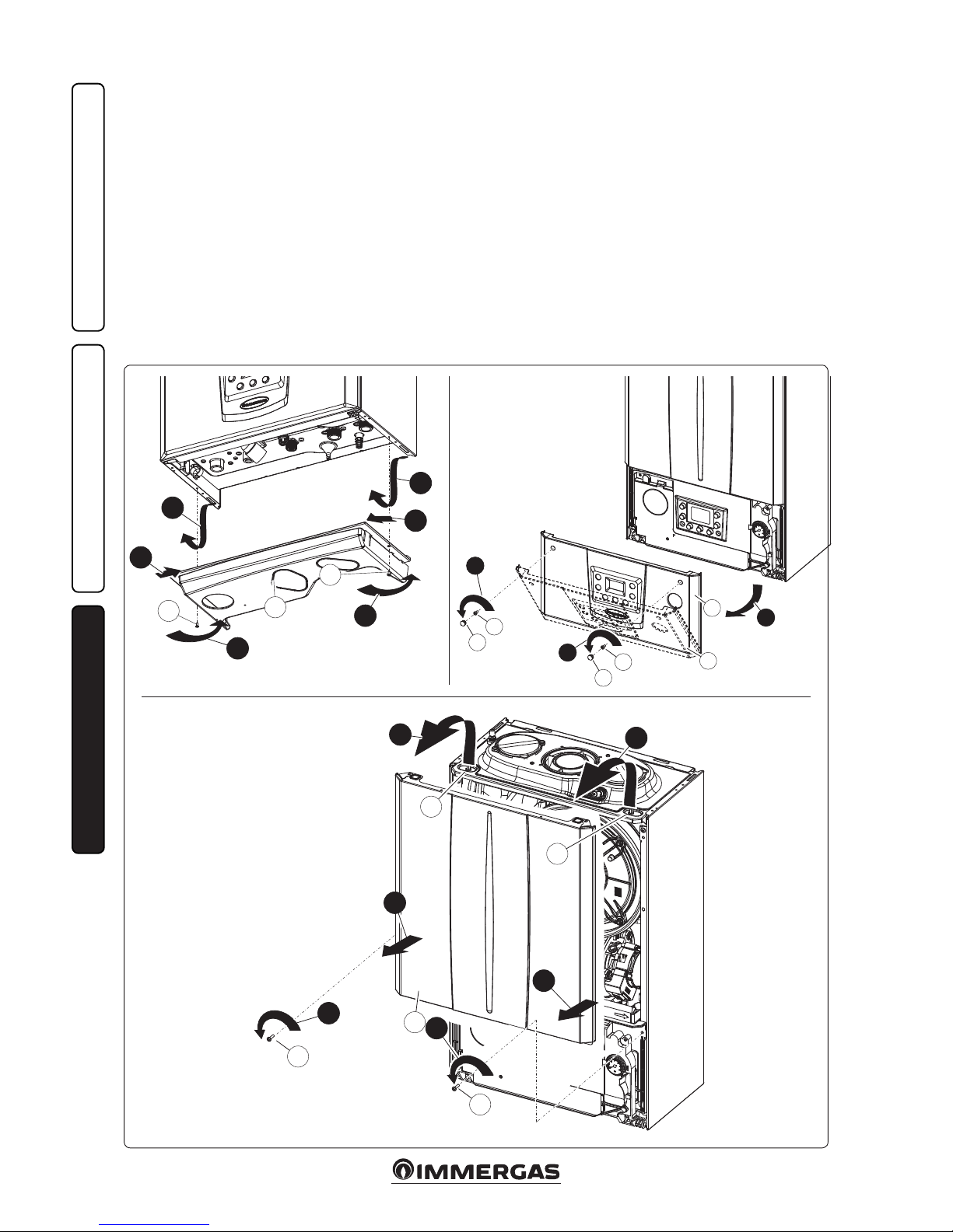
38
1
a
1
a
2
2
3
3
b
52
53
54
4
d
4
e
c
d
c
5
e1
6
g
6
g
f
8
8
h
h
7
7
INSTALLERUSERMAINTENANCE TECHNICIAN
3.20 CASING REMOVAL.
To facilitate boiler maintenance the casing can
be completely removed as follows:
• Lower grid (Fig. 52).
1) Loosen the two screws (a).
2) Press the hooks inwards, which block the
lower grid (b).
3) remove the grid (b).
• Front panel (Fig. 53).
4) Remove the cover caps (c) and loosen screws
(d).
5) Pull the front panel (e) towards you and
release it from its lower seat.
• Front (Fig. 54).
6) Loosen the two screws (g).
7) Pull the front (f) slightly towards you.
8) Release front (f) from pins (h) pulling it
towards you while pushing it upwards at the
same time.
Page 39
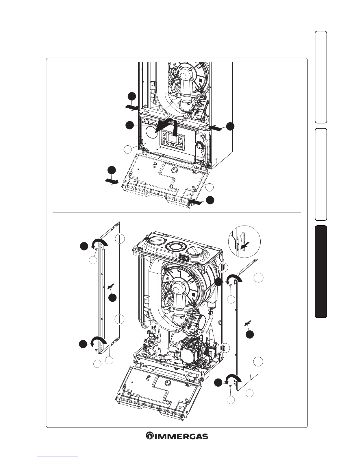
39
55
56
10
i
9
9
i
9
9
j
k
j
k
11
k
X
X
X
X
Rif. X
12
12
11
11
11
k
X
X
INSTALLERUSERMAINTENANCE TECHNICIAN
• Control panel (Fig. 55).
9) Press the hooks on the side of the control
panel (i).
10) Tilt the control panel (i) towards you.
• Sides (Fig. 56).
11) Loosen screws (k) of side fastening (j).
12) Remove the sides by extracting them from
their rear seat (Ref. X).
Page 40
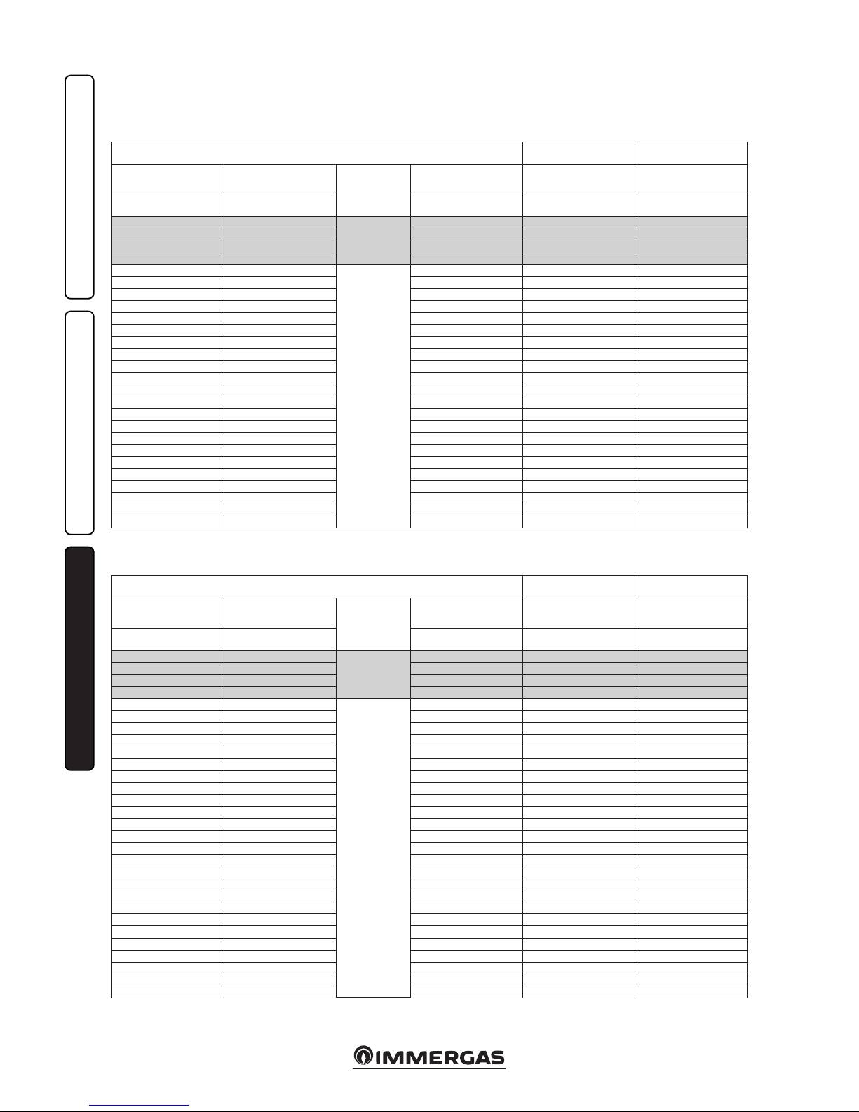
40
INSTALLERUSERMAINTENANCE TECHNICIAN
3.21 VARIABLE HEAT OUTPUT.
N.B.: the power data in the table has been ob-
tained with intake-exhaust pipe measuring 0.5 m
in length. Gas ow rates refer to net heating value
below a temperature of 15°C and at a pressure
of 1013 mbar.
Victrix Tera 28 1.
Victrix Tera 32 1.
METHANE (G20) PROPANE (G31)
HEAT POWER HEAT POWER MODULATION GAS FLOW RATE BURNER GAS FLOW RATE BURNER
(kW) (kcal/h) (%) (m3/h) (kg/h)
28.3 24295
D.H.W.
99 3.06 2.25
27.5 23650 97 2.98 2.19
26.5 22790 94 2.87 2.11
25.5 21930 90 2.76 2.03
24.1 20717
CEN. HEAT.
+
D.H.W.
85 2.61 1.91
23.5 20210 83 2.54 1.87
22.5 19350 80 2.44 1.79
21.5 18490 76 2.33 1.71
20.5 17630 72 2.22 1.63
19.5 16770 68 2.11 1.55
18.5 15910 65 2.01 1.47
17.5 15050 61 1.90 1.39
16.5 14190 57 1.79 1.31
15.5 13330 53 1.68 1.24
14.5 12470 48 1.58 1.16
13.5 11610 44 1.47 1.08
12.5 10750 40 1.36 1.00
11.5 9890 35 1.26 0.92
10.5 9030 31 1.15 0.84
9.5 8170 26 1.04 0.76
8.5 7310 22 0.93 0.68
7.5 6450 17 0.82 0.61
6.5 5590 12 0.72 0.53
5.5 4730 7 0.61 0.45
4.5 3870 2 0.50 0.37
4.3 3689 1 0.48 0.35
METHANE (G20) PROPANE (G31)
HEAT POWER HEAT POWER MODULATION GAS FLOW RATE BURNER GAS FLOW RATE BURNER
(kW) (kcal/h) (%) (m3/h) (kg/h)
32.0 27520
D.H.W.
99 3.45 2.53
31.0 26660 96 3.34 2.45
30.0 25800 92 3.24 2.38
29.0 24940 89 3.13 2.30
28.0 24080
CEN. HEAT.
+
D.H.W.
85 3.03 2.22
27.0 23220 81 2.92 2.14
26.0 22360 78 2.81 2.06
25.0 21500 74 2.70 1.98
24.0 20640 71 2.60 1.91
23.0 19780 67 2.49 1.83
22.0 18920 63 2.38 1.75
21.0 18060 60 2.28 1.67
20.0 17200 56 2.17 1.59
19.0 16340 53 2.06 1.51
18.0 15480 49 1.96 1.44
17.0 14620 45 1.85 1.36
16.0 13760 42 1.74 1.28
15.0 12900 38 1.63 1.20
14.0 12040 35 1.53 1.12
13.0 11180 31 1.42 1.04
12.0 10320 27 1.31 0.96
11.0 9460 24 1.21 0.88
10.0 8600 20 1.10 0.81
9.0 7740 17 0.99 0.73
8.0 6880 13 0.88 0.65
7.0 6020 9 0.77 0.57
6.0 5160 5 0.66 0.49
5.0 4300 2 0.55 0.41
4.9 4214 1 0.54 0.40
Page 41
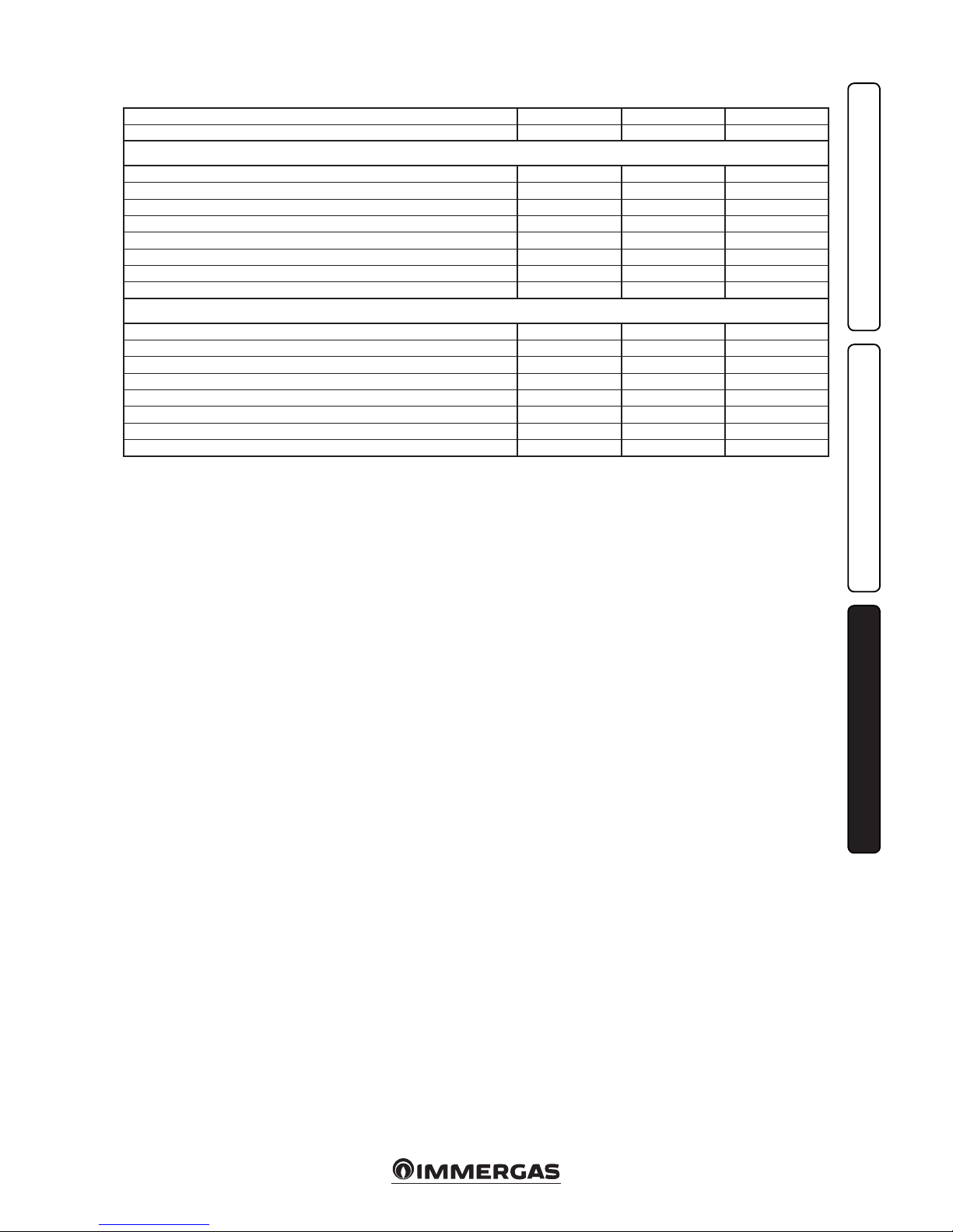
41
INSTALLERUSERMAINTENANCE TECHNICIAN
3.22 COMBUSTION PARAMETERS.
G20 G31
Supply pressure mbar (mm H2O) 20 (204) 37 (377)
Victrix Tera 28 1
Gas nozzle diameter mm 5.00 3.80
Flue ow rate at nominal heat output kg/h 44 43
Flue ow rate at min heat output kg/h 8 7
CO2 at Nom./Min. Q. % 9.70 / 8.80 11.40 / 10.60
CO with 0% O2 at Nom./Min. Q. ppm 300 / 5 400 / 5
NOX with 0% O2 at Nom./Min. Q. mg/kWh 65 / 22 81 / 36
Flue temperature at nominal output °C 70 70
Flue temperature at minimum output °C 64 63
Victrix Tera 32 1
Gas nozzle diameter mm 6.00 4.30
Flue ow rate at nominal heat output kg/h 51 50
Flue ow rate at min heat output kg/h 9 9
CO2 at Nom./Min. Q. % 9.50 / 8.60 11.20 / 10.00
CO with 0% O2 at Nom./Min. Q. ppm 250 / 2 430 / 2
NOX with 0% O2 at Nom./Min. Q. mg/kWh 56 / 18 75 / 27
Flue temperature at nominal output °C 57 60
Flue temperature at minimum output °C 58 60
Combustion parameters: measuring conditions
of useful eciency (ow temperature/return
temperature= 80 / 60 °C), ambient temperature
reference = 15°C.
Page 42

42
INSTALLERUSERMAINTENANCE TECHNICIAN
3.23 TECHNICAL DATA.
- e data relating to domestic hot water performance refer to a dynamic inlet pressure of 2 bar
and an inlet temperature of 15°C; the values
are measured immediately at the boiler outlet,
considering that to obtain the data declared,
mixing with cold water is required.
- * Eciencies refer to the lower heating value.
- e weighted NOx value refer to the net caloric
value.
Victrix Tera 28 1 Victrix Tera 32 1
Domestic hot water nominal heat input kW (kcal/h) 28,8 (24773) 32.6 (28047)
Central heating nominal heat input kW (kcal/h) 24,6 (21194) 28.6 (24588)
Minimum heat input kW (kcal/h) 4,5 (3862) 5.1 (4413)
Domestic hot water nominal heat output (useful) kW (kcal/h) 28,3 (24295) 32.0 (27520)
Central heating nominal heat output (useful) kW (kcal/h) 24,1 (20717) 28.0 (24080)
Minimum heat output (useful) kW (kcal/h) 4,3 (3689) 4.9 (4214)
*Eective thermal eciency 80/60 Nom./Min. % 97,8 / 95,5 97.9 / 95.5
*Eective thermal eciency 50/30 Nom./Min. % 106,1 / 106,1 106.0 / 108.2
*Eective thermal eciency 40/30 Nom./Min. % 108,2 / 108,3 107.9 / 108.2
Casing losses with burner On/O (80-60°C) % 0,34 / 0,20 0.30 / 0.30
Heat loss at ue with burner On/O (80-60°C) % 0,02 / 1,70 0.02 / 2.20
Central heating circuit max. operating pressure bar 3 3
Maximum central heating temperature °C 90 90
Adjustable central heating temperature (max operating eld) °C 20 - 85 20 - 85
System expansion vessel total volume l 5,8 6.4
Expansion vessel factory-set pressure bar 1,0 1.0
Appliance water content l 2,2 2.41
Head available with 1000 l/h ow rate kPa (m H2O) 26,4 (2,7) 30.1 (3.1)
Hot water production useful heat output kW (kcal/h) 28,3 (24295) 32.0 (27520)
Domestic hot water adjustable temperature °C 30 - 60 30 - 60
Domestic hot water circuit min. pressure (dynamic) bar 0,3 0.3
Domestic hot water circuit max. operating pressure bar 10 10
Flow rate capacity in continuous duty (∆T 30°C) l/min 14,1 16.5
Weight of full boiler kg 35,8 37.91
Weight of empty boiler kg 33,6 35.50
Electrical connection V/Hz 230 / 50 230 / 50
Nominal power absorption A 0,6 0.76
Installed electric power W 80 105
Pump absorbed power W 41 51
EEI value - ≤ 0,20 - Part. 3 ≤ 0,20 - Part. 3
Equipment electrical system protection - IPX5D IPX5D
Max temperature of combustion products °C 75 75
Max. ue overheating temperature °C 120 120
NOX class - 6 6
Weighted NO
X
mg/kWh 35,0 30.0
Weighted CO mg/kWh 20,0 15.0
Type of appliance
C13 / C13x / C33 / C33x / C43 / C43x / C53 / C63 / C83 / C83x / C93 / C93x /
B23 / B33 / B53p
Categor y II 2H3P
Page 43
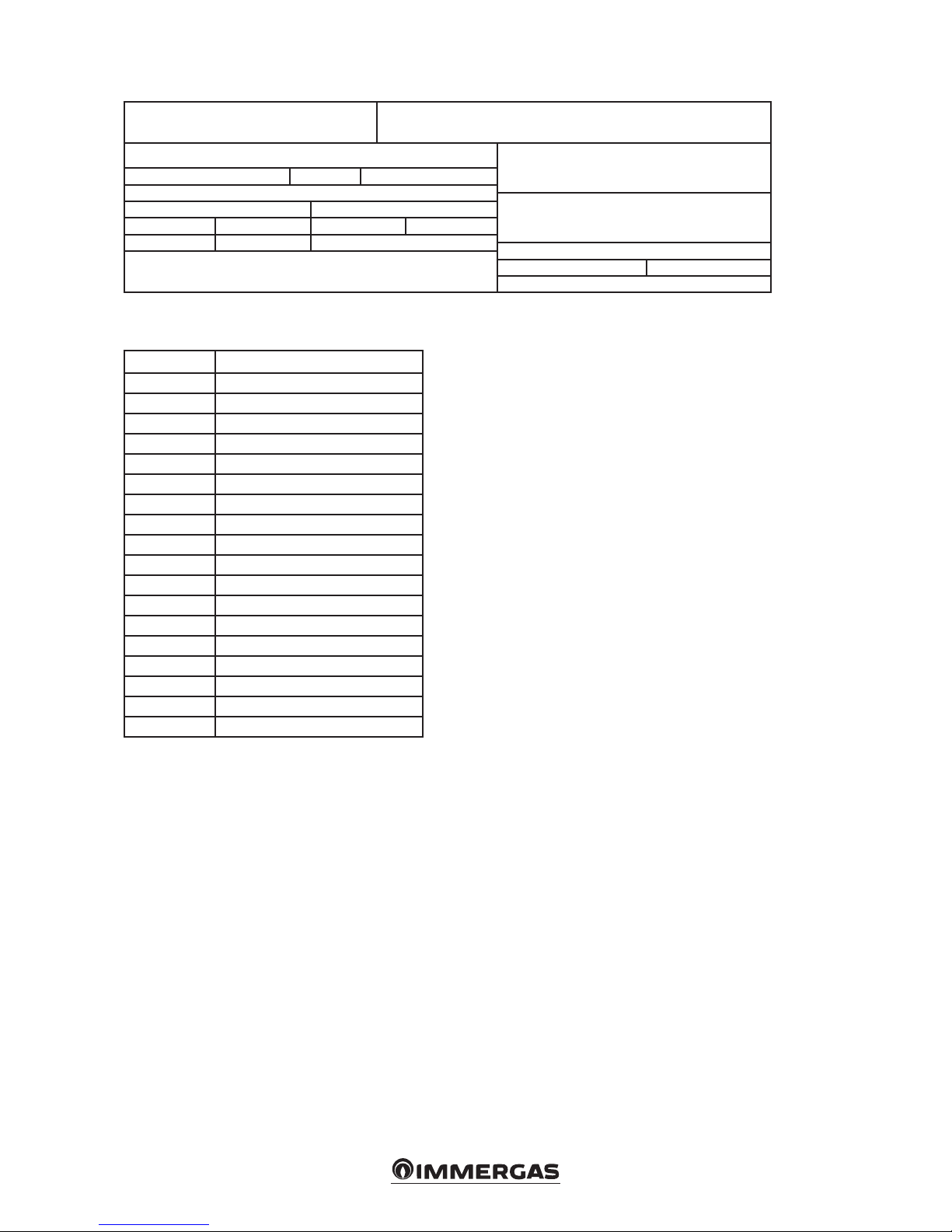
43
3.24 KEY FOR DATA NAMEPLATE.
Md Code Md
Sr N° CHK Code PIN
Type
Qnw/Qn min. Qnw/Qn max.
Pn min. Pn max.
PMS PMW D TM
NOx Class
CONDENSING
N.B.: the technical data is provided on the data plate on the boiler
IE
Md Model
Code Md Model code
Sr N° Serial Number
CHK Check
Code PIN PIN code
Typ e Type of installation (ref. CEN TR 1749)
Qnw min. Minimum DHW heat input
Qn min. CH minimum heat input
Qnw max. DHW maximum heat input
Qn max. CH maximum heat input
Pn min. Minimum heat output
Pn max. Maximum heat output
PMS Maximum system pressure
PMW Maximum domestic hot water pressure
D Specic ow rate
TM Maximum operating temperature
NOx Class NOx Class
CONDENSING Condensing boiler
Page 44

44
3.25 TECHNICAL PARAMETERS FOR COMBINATION BOILERS IN COMPLIANCE WITH REGULATION 813/2013.
Eciencies in the following tables refer to the gross caloric value.
Model/s: Victrix Tera 28 1
Condensing Boilers: YES
Low temperature boiler: NO
Boiler type B1: NO
Co-generation appliance for central heating: NO Fitted with supplementary heating system: NO
Mixed heating appliance: YES
Element Symbol Val ue Unit Element Symbol Va lue Unit
Nominal heat output P
n
24 kW
Seasonal energy eciency of central
heating
η
s
93 %
For central heating only and combination boilers: useful heat output For central heating only and combination boilers: useful eciency
At nominal heat output in high temperature mode (*)
P
4
24.0 kW
At nominal heat output in high temperature mode (*)
η
4
88.1 %
At 30% of nominal heat output in a low
temperature mode (**)
P
1
8.0 kW
At 30% of nominal heat output in a low
temperature mode (**)
η
1
97.6 %
Auxiliary electricity consumption Other items
At full load el
max
0.010 kW Heat loss in standby P
stby
0.057 kW
At partial load el
min
0.005 kW Ignition burner energy consumption P
ign
0.000 kW
In standby mode P
SB
0.002 kW Emissions of nitrogen oxides NO
X
35
mg /
kWh
For mixed central heating appliances
Stated load prole XL Domestic hot water production eciency η
WH
87 %
Daily electrical power consumption Q
elec
0.122 kWh Daily gas consumption Q
fuel
22.406 kWh
Contact information IMMERGAS S.p.A. VIA CISA LIGURE, 95 - 42041 BRESCELLO (RE) ITALY
(*) High temperature mode means 60°C on return and 80°C on ow.
(**) Low temperature mode for condensation Boilers means 30°C , for low temperature boilers 37°C and for other appliances 50°C of return temperature.
Model/s: Victrix Tera 32 1
Condensing Boilers:
Low temperature boiler:
Boiler type B1:
Co-generation appliance for central heating: Fitted with supplementary heating system:
Mixed heating appliance:
Element Symbol Va lue Unit Element Symbol Va lue Unit
Nominal heat output P
n
28 kW
Seasonal energy eciency of central
heating
η
s
93 %
For central heating only and combination boilers: useful heat output For central heating only and combination boilers: useful eciency
At nominal heat output in high temperature mode (*)
P
4
28,0 kW
At nominal heat output in high temperature mode (*)
η
4
87,85 %
At 30% of nominal heat output in a low
temperature mode (**)
P
1
9,3 kW
At 30% of nominal heat output in a low
temperature mode (**)
η
1
97,58 %
Auxiliary electricity consumption Other items
At full load el
max
0,012 kW Heat loss in standby P
stby
0,0573 kW
At partial load el
min
0,006 kW Ignition burner energy consumption P
ign
0,000 kW
In standby mode P
SB
0,002 kW Emissions of nitrogen oxides NO
X
30
mg /
kWh
For mixed central heating appliances
Stated load prole XL Domestic hot water production eciency η
WH
87 %
Daily electrical power consumption Q
elec
0,131 kWh Daily gas consumption Q
fuel
22,362 kWh
Contact information IMMERGAS S.p.A. VIA CISA LIGURE, 95 - 42041 BRESCELLO (RE) ITALY
(*) High temperature mode means 60°C on return and 80°C on ow.
(**) Low temperature mode for condensation Boilers means 30°C , for low temperature boilers 37°C and for other appliances 50°C of return temperature.
Page 45

A
B
C
D
E
F
G
A
++
A
+
A
B
C
D
E
F
G
XL
28
kW
A
VICTRIX TERA 28 1
A
52 dB
A
B
C
D
E
F
G
A
++
A
+
A
B
C
D
E
F
G
XXL
32
kW
A
VICTRIX TERA 32 1
A
55 dB
Victrix Tera 28 1 Victrix Tera 32 1
45
3.26 PRODUCT FICHE IN COMPLIANCE WITH REGULATION 811/2013.
Parameter value
Annual energy consumption for the heating function (QHE)
1,5 GJ
Annual electricity consumption for the
domestic hot water function (AEC)
27 kWh
Annual fuel consumption for the domestic
hot water function (AFC)
17 GJ
Seasonal space heating energy eciency
(ηs)
93 %
Water heating energy eciency ( ηwh) 87 %
Parameter value
Annual energy consumption for the heating function (QHE)
1,5 GJ
Annual electricity consumption for the
domestic hot water function (AEC)
29 kWh
Annual fuel consumption for the domestic
hot water function (AFC)
17 GJ
Seasonal space heating energy eciency
(ηs)
93 %
Water heating energy eciency ( ηwh) 87 %
For proper installation of the appliance refer
to chapter 1 of this booklet (for the installer)
and current installation regulations. For proper
maintenance refer to chapter 3 of this booklet (for
the maintenance technician) and adhere to the
frequencies and methods set out herein.
Page 46

46
3.27 PARAMETERS FOR FILLING THE
PACKAGE FICHE.
In case you should wish to install an assembly,
starting from the Victrix Tera (28 1 or 32 1)
boiler, use the assembly charts in Fig. 59 and 62.
To complete it properly, ll t he relevant spaces (as
shown in the assembly sheet facsimile Fig. 57 and
60) with the values shown in tables Fig. 58 and 61.
e remaining values must be obtained from
the technical data sheets of the products used
Seasonal central heating energy efciency of the boiler
1
%
Temperature control
From temperature
control board
Supplementary boiler
From boiler board
Supplementary heat pump
From the heat pump
board
Solar contribution and supplementary heat pump
Select the lowest
value
Boiler and supplementary heat pump installed with low temperature heat emitters
at 35 °C?
From the board of the heat
pump.
The energy efciency of the set of products indicated in this sheet may not reect the actual energy
efciency after installation since such efciency is affected by additional factors, such as the heat loss
in the distribution system and the size of the products compared to the size and features of the building.
Seasonal central heating energy efciency of the set
Seasonal central heating energy efciency class of the set
Solar contribution
From the board of the solar device
Class I = 1 %, Class II = 2 %,
Class III = 1.5 %, Class IV = 2 %,
Class V = 3 %, Class VI = 4 %,
Class VII = 3.5 %, Class VIII = 5 %
2
%
+
3
%
±
Seasonal central heating energy efciency
(in %)
( - ‘I’ ) x 0.1 =
( - ‘I’ ) x ‘II’ =
0.5 x O 0.5 x =
+ ( 50 x ‘II’ ) =
4
5
6
7
4 5
%
%
%
%
+
+
-
Dimensions of the
manifold (in m2)
Volume of the
tank (in m3)
Efciency of the
manifold (in %)
Classication of the
tank
A* = 0.95, A = 0.91,
B = 0.86, C = 0.83,
D-G = 0.81
( ‘III’ x + ‘IV’ x ) x (0.9 x ( / 100) x =
Seasonal central heating energy efciency
(in %)
G F E D C B A A
+++
A
++
A
+
< 30 % ≥ 30 % ≥ 34 % ≥ 36 % ≥ 75 % ≥ 82 % ≥ 90 % ≥ 98 % ≥ 125 % ≥ 150 %
%
7
‘I’
Facsimile for lling in the package che for preferential boiler space heaters.
to make up the assembly (e.g. solar devices, integration heat pumps, temperature controllers).
Use board Fig. 59 for “assemblies” related to the
central heating mode (e.g.: boiler + temperature
controller).
Use board Fig. 62 for “assemblies” related to the
domestic hot water function (e.g.: boiler + solar
thermal system).
57
Page 47

47
Parameter Victrix Tera 28 1 Victrix Tera 32 1
‘I’ 93 93
‘II’ * *
‘III’ 1.11 0,95
‘IV’ 0.44 0,37
Parameters for lling in the assembly chart.
* to be established by means of table 5 of Regulation 811/2013 in case of “assembly” including a heat
pump to integrate the boiler. In this case the boiler must be considered as the main appliance of the
assembly.
Seasonal central heating energy efciency of the boiler
1
%
Temperature control
From temperature
control board
Supplementary boiler
From boiler board
Supplementary heat pump
From the heat pump
board
Solar contribution and supplementary heat pump
Select the lowest
value
Boiler and supplementary heat pump installed with low temperature heat emitters
at 35 °C?
From the board of the heat
pump.
The energy efciency of the set of products indicated in this sheet may not reect the actual energy
efciency after installation since such efciency is affected by additional factors, such as the heat loss
in the distribution system and the size of the products compared to the size and features of the building.
Seasonal central heating energy efciency of the set
Seasonal central heating energy efciency class of the set
Solar contribution
From the board of the solar device
Class I = 1 %, Class II = 2 %,
Class III = 1.5 %, Class IV = 2 %,
Class V = 3 %, Class VI = 4 %,
Class VII = 3.5 %, Class VIII = 5 %
2
%
+
3
%
±
Seasonal central heating energy efciency
(in %)
( - ______ ) x 0.1 =
( - _____ ) x _______ =
0.5 x O 0.5 x =
4
5
6
7
4 5
%
%
%
%
+
+
-
Dimensions of the
manifold (in m2)
Volume of the
tank (in m3)
Efciency of the
manifold (in %)
Classication of the
tank
A* = 0.95, A = 0.91,
B = 0.86, C = 0.83,
D-G = 0.81
( ____ x + ____ x ) x (0.9 x ( / 100) x =
Seasonal central heating energy efciency
(in %)
G F E D C B A A
+++
A
++
A
+
< 30 % ≥ 30 % ≥ 34 % ≥ 36 % ≥ 75 % ≥ 82 % ≥ 90 % ≥ 98 % ≥ 125 % ≥ 150 %
%
7
+ ( 50 x ______ ) =
____
Room heating system package che.
58
59
Page 48
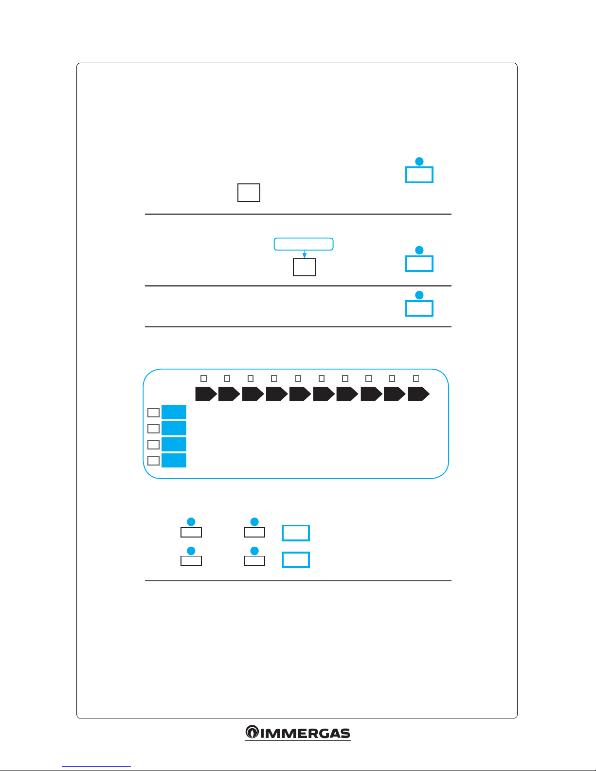
48
Water heating energy efciency of combination boiler
Water heating energy efciency of the set in
average climate conditions
Water heating energy efciency class of the set in average climate conditions
Water heating energy efciency class in colder and hotter climate conditions
Colder: - 0.2 x =
Hotter: + 0.4 x =
Stated load prole:
Solar contribution
From the board of the solar device
1
%
‘I’
2
%
+
( 1,1 x ‘I’ - 10 % ) x ‘II’ - ‘III’ - ‘I’ =
Auxiliary electricity
3
%
G F E D C B A A
+++
A
++
A
+
< 27 %
< 27 %
< 27 %
< 28 %
≥ 27 %
≥ 27 %
≥ 27 %
≥ 28 %
≥ 30 %
≥ 30 %
≥ 30 %
≥ 32 %
≥ 33 %
≥ 34 %
≥ 35 %
≥ 36 %
≥ 36 %
≥ 37 %
≥ 38 %
≥ 40 %
≥ 39 %
≥ 50 %
≥ 55 %
≥ 60 %
≥ 65 %
≥ 75 %
≥ 80 %
≥ 85 %
≥ 100 %
≥ 115 %
≥ 123 %
≥ 131 %
≥ 130 %
≥ 150 %
≥ 160 %
≥ 170 %
≥ 163 %
≥ 188 %
≥ 200 %
≥ 213 %
M
L
XL
XXL
3 2
3 2
%
%
The energy efciency of the set of products indicated in this sheet may not reect the actual energy
efciency after installation since such efciency is affected by additional factors, such as the heat loss
in the distribution system and the size of the products compared to the size and features of the building.
Facsimile for lling in domestic hot water production system package che.
60
Page 49
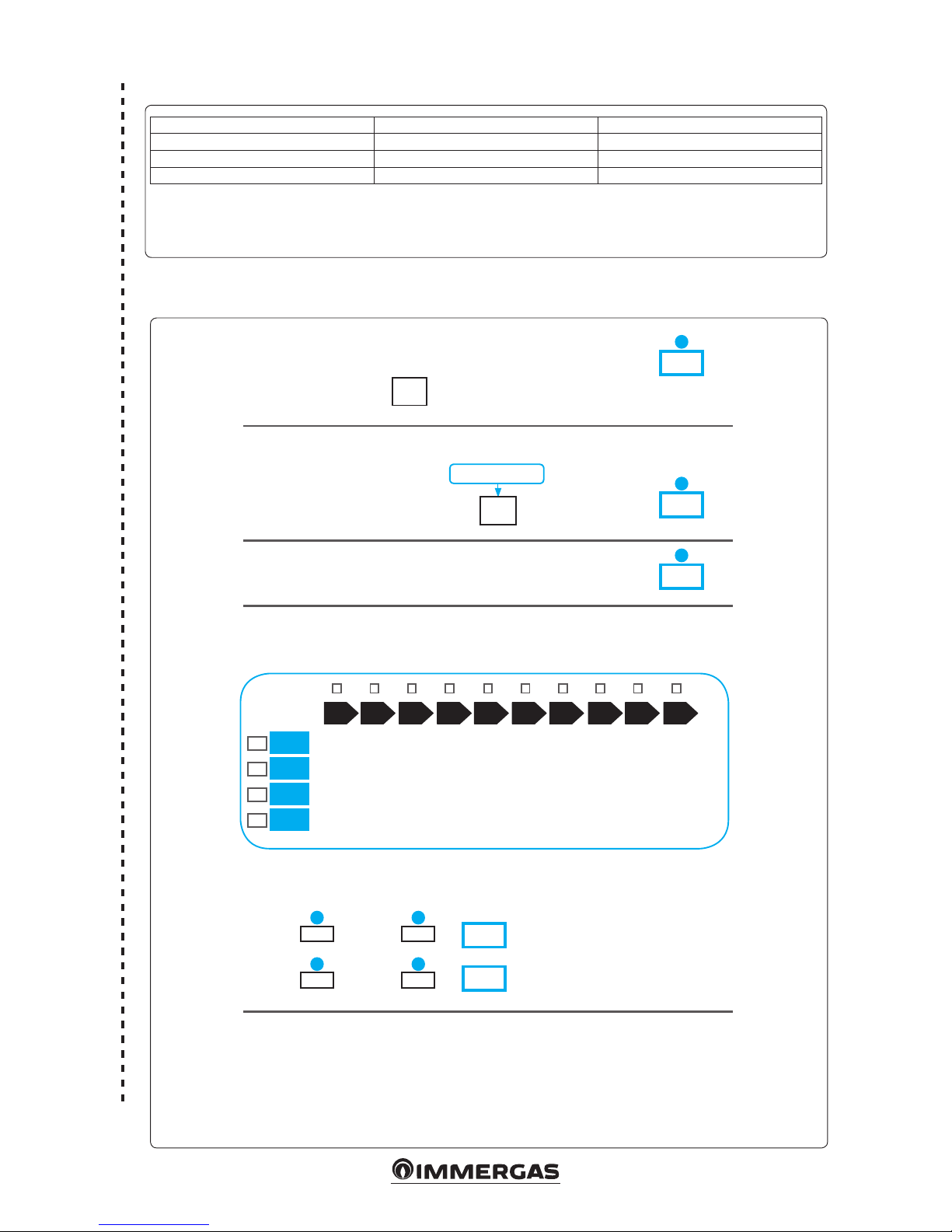
49
Water heating energy efciency of combination boiler
Water heating energy efciency of the set in
average climate conditions
Water heating energy efciency class of the set in average climate conditions
Water heating energy efciency class in colder and hotter climate conditions
Colder: - 0.2 x =
Hotter: + 0.4 x =
Stated load prole:
Solar contribution
From the board of the solar device
1
%
_____
2
%
+
( 1.1 x _____ - 10 % ) x _____ - ____ - ______ =
Auxiliary electricity
3
%
G F E D C B A A
+++
A
++
A
+
< 27 %
< 27 %
< 27 %
< 28 %
≥ 27 %
≥ 27 %
≥ 27 %
≥ 28 %
≥ 30 %
≥ 30 %
≥ 30 %
≥ 32 %
≥ 33 %
≥ 34 %
≥ 35 %
≥ 36 %
≥ 36 %
≥ 37 %
≥ 38 %
≥ 40 %
≥ 39 %
≥ 50 %
≥ 55 %
≥ 60 %
≥ 65 %
≥ 75 %
≥ 80 %
≥ 85 %
≥ 100 %
≥ 115 %
≥ 123 %
≥ 131 %
≥ 130 %
≥ 150 %
≥ 160 %
≥ 170 %
≥ 163 %
≥ 188 %
≥ 200 %
≥ 213 %
M
L
XL
XXL
3 2
3 2
%
%
The energy efciency of the set of products indicated in this sheet may not reect the actual energy
efciency after installation since such efciency is affected by additional factors, such as the heat loss
in the distribution system and the size of the products compared to the size and features of the building.
Parameter Victrix Tera 28 1 Victrix Tera 32 1
‘I’ 87 87
‘II’ * *
‘III’ * *
Parameters for lling in DHW package assembly chart.
* to be determined according to Regulation 811/2013 and transient calculation methods
as per Notice of the European Community no. 207/2014.
Domestic hot water production system package che.
61
62
Page 50

Page 51

Page 52
Follow us
Immergas Italia
immergas.com
Immergas S.p.A.
42041 Brescello (RE) - Italy
Tel. 0522.689011
Fax 0522.680617
Certied company ISO 9001
is instruction booklet is made of ecological paper Cod. 1.040295ENG - rev. ST.002849/000 - 03/17 - Inglese per IRLANDA (IE)
 Loading...