

Page 1

VICTRIX Superior 32 kW X
CALOR SRL
Str. Progresului nr. 30-40, sector 5, Bucuresti
tel: 021.411.44.44, fax: 021.411.36.14
www.calorserv.ro - www.calor.ro
Podręcznik obsługi
PL
wraz z instrukcjami
Talimat ve uyarılar kitapçığı
TR
Návod k použití a upozornění
CZ
Használati utasítás
HU
és gyelmeztetések
Manual de instrucţiuni
RO
şi recomandări
Instruction booklet
IE
and warning
Page 2

HU IERO
Gratulálunk, hogy egy, a csúcsminőséget képviselő
Immergas terméket vásárolt, amely hosszú ideig és
biztonságosan fogja az Ön kényelmét szolgálni. Az
Immergas vásárlóinak bármikor rendelkezésére
áll a cég szakképzett szervízhálózata, amely naprakészen biztosítja az Ön készülékének folyamatos
hatékonyságát.
Figyelmesen olvassa át a következő oldalakat: hasznos tanácsokat kaphat készüléke helyes használatával kapcsolatban, amelyeket követve biztosan meg
lesz elégedve az Immergas termékével.
Minél hamarabb lépjen kapcsolatba az Önhöz
legközelebbi szervízzel, és kérje az üzembe helyezési szolgáltatásunkat. Szakemberünk ellenőrzi a
készülék megfelelő működési feltételeinek meglétét,
elvégzi a szükséges beállításokat, és elmagyarázza
Önnek a készülék helyes üzemeltetését.
Amennyiben javítás vagy karbantartás válik
szükségessé, forduljon az Immergas szakszerviz
központajaihoz: ezek szükség esetén eredeti alkatrészeket biztosítanak és közvetlenül a gyártótól eredő
felkészüléssel büszkélkedhetnek.
A használati útmutató szerves és elengedhetetlen
része a terméknek, ezért fontos, hogy a felhasználó
átruházás esetén azt is kézhez kapja.
Az útmutatót gondosan meg kell őrizni és gyelmesen át kell tanulmányozni, mivel biztonsági szempontból fontos utasításokat tartalmaz az instalálás,
a használat és a karbantartás tekintetében.
Az instalálást és a karbantartást az érvényben lévő
egyéb jogszabályok értelmében csakis megfelelő
szakirányú képzettséggel rendelkező szakember
végezheti az érvényes előírások betartásával, a
gyártó útmutatása szerint.
A hibás instalálás személyi, állati és tárgyi sérüléseket okozhat, amelyekért a gyártó nem vállal
felelősséget. A karbantartást csak felhatalmazott
szakember végezheti, ebben a tekintetben az
Immergas szakszervízek hálózata a minőség és a
szakértelem biztosítéka.
A készüléket csakis eredeti rendeltetési céljának
megfelelően szabad használni. Minden egyéb alkalmazása nem rendeltetésszerűnek, ennél fogva
veszélyesnek minősül.
A hatályos jogszabályban foglalt műszaki
előírásoknak vagy a jelen útmutató utasításainak
(illetve a gyártó egyéb rendelkezéseinek) be nem
tartásából fakadó helytelen instalálás, használat
vagy karbantartás esetén a gyártót semmilyen
szerződéses vagy szerződésen kívüli felelősség
nem terheli, és érvényét veszíti a készülékre vállalt
jótállása is.
A gázüzemű hőfejlesztők beszerelésére vonatkozó
jogszabályokról bővebb információkat az Immergas
honlapján találhat, a következő címen: www.
immergas.com
CE SZABVÁNYOSSÁGI NYILATKOZAT
A 90/396/EK Gáz irányelv, a 89/336/EK EMC irányelv, a 92/42/EK Hatásfok irányelv és a 73/23/EK
Alacsony feszültségű irányelv értelmében .
A Gyártó: Immergas S.p.A. v. Cisa Ligure n° 95
42041 Brescello (RE)
KIJELENTI HOGY: az Immergas kazánok, modell:
Victrix Superior 32 kW X
megfelelnek a az előírt EU Közösségi szabványoknak
Kutatási és Fejlesztési igazgató
Mauro Guareschi Aláírás:
Kedves Vásárló!
Általános tudnivalók
Vă felicităm pentru ca aţi ales un produs Immergas
de calitate superioară în măsură să vă asigure
bunăstare şi siguranţă pe termen lung. În calitate
de client Immergas veţi putea conta întotdeauna pe
un Serviciu calicat de Asistenţă Autorizat, pregătit
şi actualizat pentru a garanta ecienţă constantă
centralei dumneavoastră.
Citiţi cu atenţie paginile următoare: veţi putea
regăsi sugestii utile privind corecta utilizare a aparatului, ale căror respectare va conrma satisfacţia
dumneavoastră pentru produsul Immergas.
Adresaţi-vă imediat centrului nostru de Asistenţă
Autorizat zonal pentru verificarea iniţială a
funcţionării. Tehnicianul nostru va verifica
condiţiile de funcţionare, va executa reglările necesare de calibrare şi vă va indica utilizarea corectă
a generatorului.
Adresaţi-vă pentru eventuale necesităţi de
intervenţie şi întreţinere obişnuită Centrelor Autorizate Immergas: acestea dispun de componente
originale şi presupun o pregătire specică în grija
directă a constructorului.
Manualul de instrucţiuni constituie parte integrantă
şi esenţială a produsului şi va trebui să e înmânat
utilizatorului şi în caz de transfer de proprietate.
Acesta va trebui să e păstrat cu atenţie şi consultat
atent, întrucât toate avertismentele furnizează
indicaţii importante pentru siguranţă în fazele de
instalare, uz şi întreţinere.
Instalarea şi întreţinerea trebuie să e efectuate
cu respectarea normelor în vigoare, conform
instrucţiunilor constructorului şi de personal
calicat profesional, înţelegând prin aceasta pe
acela care deţine competenţa specică tehnică în
domeniul instalaţiilor.
O instalare greşită poate cauza daune persoanelor,
animalelor sau lucrurilor, pentru care constructorul nu este responsabil. Întreţinerea trebuie să e
efectuată de personal tehnic abilitat, Serviciul de
Asistenţă Tehnică Autorizat Immergas reprezintă
în acest sens o garanţie de calicare şi de profesionalism.
Aparatul va trebui să e destinat doar utilizării pentru care a fost expres prevăzut. Orice altă utilizare se
consideră improprie şi aşadar periculoasă.
În caz de erori în instalare, utilizare sau întreţinere,
datorate nerespectării legislaţiei tehnice în vigoare, a normei sau a instrucţiunilor din manualul
de faţă (sau oricum furnizate de constructor),
se exclude orice responsabilitate contractuală şi
extracontractuală a constructorului pentru daune
şi se pierde garanţia privind aparatul.
Pentru informaţii ulterioare privind dispoziţiile
normative referitoare la instalarea generatoarelor de
căldură pe bază de gaz, consultaţi site-ul Immergas
la următoarea adresă: www.immergas.com
DECLARAŢIE CE DE CONFORMITATE
Potrivit Directivei gaz CE 90/396, Directiva EMC
CE 89/336, Directiva randamente CE 92/42 şi
Directiva Joasă Tensiune CE 73/23.
Constructorul: Immergas S.p.A v. Cisa Ligure nr.
95 42041 Brescello (RE)
DECLARĂ CĂ: centralele Immergas model:
Victrix Superior 32 kW X
Sunt conforme cu aceleaşi Directive Comunitare
Director Cercetare & Dezvoltare
Mauro Guareschi Semnatura:
Stimate client,
Avertismente generale
Our compliments for having chosen a top-quality
Immergas product, able to assure well-being and
safety for a long period of time. As an Immergas
customer you can also count on a qualied aersales service, prepared and updated to guarantee
constant eciency of your boiler.
Read the following pages carefully: you will be able
to draw useful suggestions regarding the correct use
of the appliance, the respect of which, will conrm
your satisfaction for the Immergas product.
Contact our area authorised aer-sales centre as
soon as possible to request commissioning. Our
technician will verify the correct functioning conditions; he will perform the necessary calibrations and
will demonstrate the correct use of the generator.
For any interventions or routine maintenance
contact Immergas Authorised Centres: these have
original spare parts and boast of specic preparation
directly from the manufacturer.
e instruction book is an integral and important
part of the product and must be consigned to the
user also in the case of transfer of ownership.
It must be kept well and consulted carefully, as all
of the warnings supply important indications for
safety in the installation, use and maintenance
stages.
Installation and maintenance must be performed in
compliance with the regulations in force, according
to the manufacturer and professionally qualied
sta, intending sta with specic technical skills
in the plant sector.
Incorrect installation can cause injury to persons
and animals and damage to objects, for which the
manufacturer is not liable. Maintenance must be
carried out by skilled technical sta. e Immergas
Authorised Aer-sales Service represents a guarantee of qualications and professionalism.
e appliance must only be destined for the use
for which it has been expressly declared. Any other
use must be considered improper and therefore
dangerous.
In the case of errors during installation, running
and maintenance due to the failure to comply with
the technical laws in force, standards or the instructions contained in this book (or however supplied
by the manufacturer), the manufacturer is excluded
from any contractual and extra-contractual liability
for any damages and the appliance warranty is
invalidated.
For further information regarding legislative and
statutory provisions relative to the installation of
gas heat generators, consult the Immergas site at the
following address: www.immergas.com
For the purpose and eect of the CE 90/396 Gas
Directive, EMC CE 89/336 Directive, CE 92/42
Boiler Eciency Directives and CE 73/23 Low
Voltage Directive.
e Manufacturer: Immergas S.p.A. v. Cisa Ligure
n° 95 42041 Brescello (RE)
DECLARES THAT: the Immergas boiler model:
Victrix Superior 32 kW X
is in compliance with the same European Community Directives
Research & Development Director
Mauro Guareschi Signature:
Dear Customer,
General recommendations
DECLARATION OF CONFORMITY
3
Page 3
HU IERO
A KAZÁN BESZERELÉSE.
1
BESZERELŐ
1.1 BESZERELÉSI TUDNIVALÓK.
Az Victrix Superior kW X kazánt kizárólag falra
lehet felszerelni, a készülék helyiségek fűtésére és
használati melegvíz előállítására, háztartási vagy
ahhoz hasonló célokra használható.
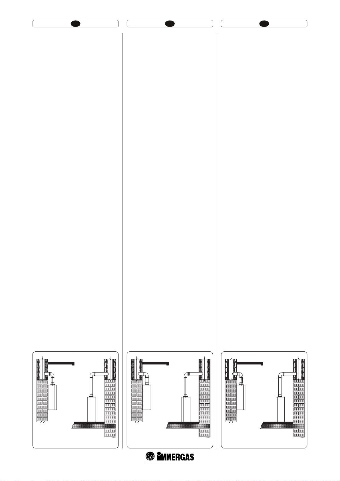
A falfelületnek simának kell lennie, vagyis nem
lehetnek rajta olyan kiálló vagy beugró részek, melyek hozzáférhetővé tennék a készülék hátsó részét.
Nem alapokra vagy padlózatra történő beszerelésre
alakítottuk ki (lásd az 1-1. ábrát).
A beszerelés típusának megváltoztatásával a kazán
típusa is változik:
- B
23
típusú kazánse, ha a beszerelés helyiségéből
szívja be közvetlenül a levegőt az erre a célra
szolgáló végelem felhasználásával.
- C típusú kazán, ha koncentrikus csöveket vagy
más típusú vezetékeket használ a hermetikusan
zárt kazán levegő beszívására és füstelvezetésére.
Az Immergas gázkészülékeket csakis megfelelő szakmai képesítéssel rendelkező víz – gáz – fűtésszerelő
szakember telepítheti.
A beszerelést a szabványoknak, az érvényes jogszabályoknak és a helyi műszaki előírásoknak
megfelelően, az elvárható legnagyobb szakértelemmel kell elvégezni.
Telepítés előtt ellenőrizni kell, hogy a készülék nem
sérült-e meg a szállítás során, kétely esetén
haladéktalanul forduljon a viszonteladóhoz. A csomagolóanyagokat (kapcsokat, szegeket, műanyag
zacskókat, polisztirolt, stb.) ne hagyja gyermekek
keze ügyében, mivel ezek veszélyesek lehetnek.
Amennyiben a készülék bútorok között vagy
szekrénybe kerül elhelyezésre, elegendő helyet kell
biztosítani a karbantartási műveletek számára, ezért
tanácsos a kazán burkolata és a szekrény fala között
legalább 3 cm-nyi helyet hagyni. A kazán felett és
alatt hagyjon helyett, hogy el lehessen végezni a
vízvezetékek és kéményrendszer javítását. A készülék közelében ne legyen semmilyen tűzveszélyes
tárgy (papír, rongy, műanyag, polisztirol stb.).
Javasoljuk, hogy ne helyezzen elektromos háztartási
készülékeket a kazán alá, mert a biztonsági szelep
beavatkozása esetén (ha nincs megfelelően egy
elvezető tölcsérhez csatlakoztatva) vagy amennyiben a vízcsatlakozások eresztenek, megsérülhetnek . Ellenkező esetben a gyártó nem felelős az
elektromos háztartási készülékekben keletkezett
károkért.
Rendellenesség, üzemzavar vagy nem tökéletes
működés esetén a készüléket ki kell kapcsolni és
szakembert kell hívni (például az Immergas
szakszervizt, amelynek szakemberei a legjobban
ismerik a cég gyártmányait és eredeti cserealkatrészeket építenek be). Ne kísérletezzünk a hiba
kijavításával.
A fentiek figyelmen kívül hagyása személyes
felelősséggel és a jótállás elveszítésével jár.
INSTALARE CENTRALĂ.
1
INSTALATOR
1.1 AVERTISMENTE PRIVIND INSTALAREA
Centrala termică Victrix Superior kW X a fost
proiectată numai pentru instalarea pe perete;
pentru încălzirea spaţiilor pentru uzul domestic
şi asemănător.
Peretele trebuie să fie drept, fără denivelări şi
proeminenţe în măsură să permită accesul dinspre
partea posterioară. Aceste centrale nu sunt proiectate pentru instalarea pe pământ sau pe podea
(Fig. 1-1).
Variind tipul de instalare, variază şi clasicarea
centralei, şi anume:
- Centrală de tip B
terminalul corespunzător pentru aspirarea
aerului direct din locul în care este instalată
centrala.
- Centrală de tip C dacă este instalată folosind tu-
buri concentrice sau alte tipuri de ţevi prevăzute
pentru centrale cu cameră etanş pentru aspirarea
aerului şi expulzarea gazelor arse.
Numai un instalator, calicat profesional este autorizat să instaleze aparaturile pe gaz Immergas.
Instalarea trebuie efectuată respectând normele
şi legislaţia în vigoare, cu respectarea normelor
tehnice locale şi ale bunei tehnici.
Înainte de instalarea aparatului este necesar să se
verice dacă acesta a ajuns integru; dacă acest lucru
nu este cert, trebuie să vă adresaţi imediat furnizorului. Elementele ambalajului (cleme, cuie, saci de
plastic, etc..), nu trebuie lăsate la îndemâna copiilor
întrucât sunt periculoase. În cazul în care aparatul
este montat între obiecte de mobilă, trebuie lăsat
un spaţiu sucient pentru normala întreţinere; este
recomandat să se lase cel puţin 3 cm între învelişul
centralei şi părţile verticale ale mobilei. Deasupra
şi dedesubtul cazanului trebuie lăsat spaţiu pentru a
permite intervenţii asupra racordurilor hidraulice şi
sistemelor de evacuare a gazelor arse. Niciun obiect
inamabil nu trebuie să se găsească în apropierea
aparatului (hârtie, plastic, polistirol, etc.).
Se recomandă a nu aşeza aparate electrocasnice
sub centrală, pentru că ar putea suferi daune în
caz de intervenţie a supapei de siguranţă (dacă nu
este legată corespunzător la o pâlnie de descărcare),
sau în cazul unor pierderi pe lângă racordurile
hidraulice; în caz contrar constructorul nu va
responsabil pentru eventualele avarii cauzate aparatelor electrocasnice.
În caz de anomalie, defecţiune sau funcţionare
necorespunzătoare, aparatul trebuie dezactivat şi
este necesară chemarea unui tehnician calicat (de
exemplu centrul de Asistenţă Tehnică Immergas,
care dispune de o pregătire tehnică specică şi
de piese originale de schimb). Nu efectuaţi nicio
intervenţie sau reparaţie.
Nerespectarea celor enumerate mai sus determină
responsabilitatea personală şi ineficacitatea
garanţiei.
s dacă este instalată folosind
23
INSTALLATION OF THE BOILER
1
INSTALLER
1.1 INSTALLATION RECOMMENDA
TIONS.
e Victrix Superior kW X boiler has been designed
uniquely for wall-installation, for the heating of
rooms for domestic use and similar.
e wall surface must be smooth, without any protrusions or recesses enabling access to the rear part.
ey are NOT designed to be installed on plinths
or oors (Fig. 1-1).
By varying the type of installation the classication
of the boiler also varies, precisely:
- Type B boiler
terminal for air intake directly from the room
in which the boiler has been installed.
- Type C boiler if installed using concentric pipes
or other types of pipes envisioned for the sealed
chamber boiler for intake of air and expulsion
of fumes.
Only professionally qualied heating/plumbing
technicians are authorised to install Immergas gas
appliances.
Installation must be carried out according to the
standards, current legislation and in compliance
with local technical regulations and the required
technical procedures.
Before installing the appliance, ensure that it is
delivered in perfect condition; if in doubt, contact the supplier immediately. Packing materials
(staples, nails, plastic bags, polystyrene foam,
etc.) constitute a hazard and must be kept out of
the reach of children. If the appliance is installed
inside or between cabinets, ensure sucient space
for normal servicing; therefore it is advisable to
leave a clearance of at least 3 cm between the boiler
casing and the vertical sides of the cabinet. Leave
adequate space above the boiler for possible water
and fume removal connections. Keep all ammable
objects away from the appliance (paper, rags, plastic,
polystyrene, etc.).
Do not place household appliances underneath the
boiler as they could be damaged if the safety valve
intervenes (if not conveyed away by a discharge
funnel), or if there are leaks from the connections;
on the contrary, the manufacturer cannot be held
responsible for any damage caused to the household
appliances.
In the event of malfunctions, faults or incorrect
operation, turn the appliance o immediately and
contact a qualied technician (e.g. the Immergas
Technical Assistance centre, which has specically
trained personnel and original spare parts) Do not
attempt to modify or repair the appliance alone.
Failure to comply with the above implies personal
responsibility and invalidates the warranty.
if installed using the relevant
23
IGEN
NEM
1-1
DA
5
NU
1-1
YES
NO
1-1
Page 4

HU IERO
t 5FMFQÓUÏTJT[BCÈMZPL F[ BLB[ÈOGFMT[FSFMIFUʩ
külső, részlegesen védett térbe. Részlegesen
védett külső tér alatt olyan hely értendő, ahol
a kazánt nem éri közvetlenül és belsejébe nem
juthat csapadék (eső, hó, jégeső stb.).
Figyelem! A falra történő rögzítésnek kellően
stabilan és biztonságosan kell tartania a hőtermelő
készüléket.
A tipliket (készülékhez adott csomagban), amennyiben a kazánt kiegészíti egy tartó kengyel vagy rögzítés
sablon, kizárólag a kazánnak a falra rögzítéséhez
lehet használni! ; Csak abban az esetben biztosíta-
nak megfelelő stabilitást, ha tömör vagy féltömör
téglából rakott falba, helyesen (szakszerűen)
kerülnek felszerelésre. Üreges téglából vagy falazó
elemből készült fal vagy korlátozott teherbírású
válaszfal, illetve a fentiektől eltérő falszerkezet
esetén előzetesen ellenőrizni kell a tartórendszer
statikai terhelhetőségét.
Megj: a tiplikhez való hatszög fejű csavarokat
kizárólag a fali tartó kengyel rögzítéséhez szabad
használni.
Ezek a kazánok arra szolgálnak, hogy vizet melegítsenek fel atmoszférikus nyomásnál forráspont
alatti hőmérsékletre.
Csakis rendeltetésüknek és teljesítményüknek
megfelelő fűtési rendszerre és vízhálózatra csatlakoztathatók.
t /PSNFEF JOTUBMBSFBDFBTUʅDFOUSBMʅQPBUF ĕ
instalată în exterior, într-un loc parţial protejat. Prin loc parţial protejat se înţelege acela
în care centrala nu este expusă direct acţiunii
precipitaţiilor atmosferice (ploaie, zăpadă,
grindină, etc..).
Atenţie: instalarea centralei pe perete, trebuie să
garanteze o susţinere stabilă şi ecace generatorului însuşi.
Diblurile (furnizate de serie), în cazul în care este
prezent un suport de susţinere sau de xare împreună
cu centrala, vor utilizate exclusiv pentru xarea
centralei la perete; pot asigura o susţinere adecvată
dacă sunt introduse corect (conform normelor
unei bune tehnici) în pereţii construiţi cu cărămizi
pline sau semipline. În cazul pereţilor realizaţi în
cărămidă sau blocuri de ciment, pereţi despărţitori
cu staticitate limitată sau oricum ziduri diferite de
cele enumerate, este necesar să se procedeze la o vericare preliminară statică a sistemului de suport.
N.B.: şuruburile pentru dibluri, cu capul hexagonal, prezente în blister, vor utilizate exclusiv
pentru xarea respectivului suport de susţinere
la perete.
Aceste centrale se utilizează pentru încălzirea apei
la o temperatură inferioară celei de fierbere la
presiune atmosferică.
Trebuie să e racordate la o instalaţie de încălzire
adecvată şi la o reţea de distribuţie a apei menajere
adecvată prestaţiilor acestora şi capacităţii lor.
t *OTUBMMBUJPOSFHVMBUJPOTUIJT CPJMFSDBOCF JO-
stalled outside in a partially protected area. A
partially protected location is one in which the
appliance is not exposed to the direct action of
the weather (rain, snow, hail, etc..).
Important: Wall mounting of the boiler must
guarantee stable and efficient support for the
generator.
e plugs (standard supply) are to be used only in
conjunction with the mounting brackets or xing
template to x the appliance to the wall; they only
ensure adequate support if inserted correctly (according to technical standards) in walls made of
solid or semi-hollow brick or block. In the case of
walls made from hollow brick or block, partitions
with limited static properties, or in any case walls
other than those indicated, a static test must be
carried out to ensure adequate support.
N.B.: the hex head screws supplied in the blister
pack are to be used exclusively to x the relative
mounting bracket to the wall.
ese boilers are used to heat water to below boiling
temperature in atmospheric pressure.
ey must be connected to a heating system and
hot water circuit suited to their performance and
capacity.
7
Page 5
PL CZTR
1.2 GŁÓWNE WYMIARY.
* = kocioł jest wyposażony w zawór kurkowy gazu
90° z przyłączami 3/4” i złączką Ø18 mm.
Opis (Rys. 1-2):
V - Podłączenie elektryczne
G - Zasilanie gazu
RU - Powrót jednostki grzewczej (opcja)
MU - Wyjście jednostki grzewczej (opcja)
RR - Uzupełnienie instalacji
SC - Odprowadzenie kondensatu
(minimalny przekrój wewnętrzny Ø 13 mm)
R - Powrót instalacji
M - Odpływ instalacji
1.3 OCHRONA PRZECIW
ZAMARZNIĘCIU.
Temperatura minimalna -3°C. Kocioł wyposażony
jest seryjnie w funkcję przeciw zamarzaniu, która
uruchamia pompę i palnik gdy temperatura wody
wewnątrz kotła zejdzie poniżej 4°C.
Funkcja przeciw zamarzaniu jest zapewniona
wyłącznie, gdy:
- kocioł jest właściwie podłączony do obwodów
zasilania gazem i elektrycznego;
- kocioł jest nieustannie zasilany;
- kocioł nie jest w stand-by (
- kocioł nie jest zablokowany z powodu braku
zapłonu (parag. 2.6);
- istotne komponenty kotła nie mają awarii.
W tych warunkach kocioł jest chroniony przed mrozem do temperatury otoczenia -3°C.
Temperatura minimalna -15°C. W przypadku,
gdy kocioł zainstalowany byłby w miejscu, gdzie
temperatura jest niższa niż -3°C i gdyby zabrakło
zasilania gazem, lub kocioł zablokowałby się z
powodu braku zapłonu, można doprowadzić do
zamarznięcia urządzenia.
Aby uniknąć ryzyka zamarznięcia zastosować się do
następujących wskazówek:
- Chronić przed mrozem obwód ogrzewania
wprowadzając do niego płyn przeciw zamarzaniu (konkretny dla instalacji grzejnych)
dobrej jakości, stosując się ściśle do instrukcji
producenta płynów, jeśli chodzi o potrzebną
ilość wzgledem minimalnej temperatury wktórej
chcemy przechować instalację.
Materiały, z których wykonane zostały kotły są
wytrzymałe na płyny przeciwzamarzaniu o podstawie z glikoli etylenowych i propylenowych.
Czas trwałości i ewentualny zbyt - dostosować się
do wskazówek producenta.
)
1.2 ANA BOYUTLAR.
* = kombi 3/4” bağlantılı ve Ø18mm rakorlu
90° bir gaz musluğu ile donatılmıştır.
Açıklamalar (Şekil 1-2) :
V - Elektrik bağlantısı
G - Gaz girişi
RU- Boyler birimi geri dönüş (opsiyonel)
MU - Boyler birimi gönderim (opsiyonel)
RR - Tesisat dolumu
SC - Kondensasyon tahliye (asgari iç çap Ø 13 mm)
R - Tesisat dönüşü
M - Tesisat salımı
1.3 BUZLANMAYA KARŞI KORUMA.
Asagari ısı -3°C. Kombi cihazı, içerisindeki suyun
-4°C derecenin altına inmesi halinde otomatik olarak pompa ve boyleri devreye sokarak buzlanmayı
önleyici bir sistemi bulunmaktadır.
Buzlanmaya karşı koruma ancak aşağıdaki şartlarda
sağlanır :
- kombinin düzenli bir şekilde gaz ve elektrik
girişlerine bağlı olması ;
- kombi cihazının girişlerinin sağlanması;
- kombi stand-by konumunda değildir (
- kombinin ateşleme olmadığından ötürü arıza
halinde olmaması (paragraf. 2.6);
- kombi cihazının ana aksamının arızalı
olmaması.
Bu şartlarda kombi cihazı ortam ısısının -3°C
dereceye kadar düşmesi halinde buzlanmaya karşı
koruma altındadır.
Asgari ısı -15°C. Kombi cihazının ısının -3°C nin
altına düştüğü bir ortamda monte edilmiş olması
halinde ve de gaz girişinin kesilmesi veyahut da
ateşleme yapılamadığı için arızaya geçmesi durumunda buzlanma önleyici sistem devreye giremez
ve cihazda buzlanma oluşur.
Buzlanma tehlikesinin önlenmesi amacıyla aşağıda
belirtilen kurallara uyunuz :
- Tesisattaki buzlanmayı önleyebilmek amacıyla,
bu devreye kaliteli marka bir antifriz konulması
(kalorifer tesisatları için özel mamul) tavsiye olunur, bu amaçla üretici rma tarafından cihazın
kaç derecelik düşük ısılarda korunmasının
arzulandığına göre belirlenen antifriz karışım
oranlarını dikkate alınız.
Kombi cihazlarının üretilmiş olduğu malzemeler
etilen glikol ve propilen bazlı antifrizlere karşı
dayanıklıdırlar.
Bunların ömrü ve muhtemel imhaları konusunda
tedarikçi rma uyarılarına riayet ediniz.
)
1.2 HLAVNÍ ROZMĚRY.
1-2
* = kotel je vybaven plynovým kohoutem 90° s
přípojkami 3/4” a spojkou o průměru 18 mm.
Legenda (Obr. 1-2):
V - Elektrické připojení
G - Přívod plynu
RU - Návrat jednotky ohřívače (volitelně)
MU - Náběh jednotky ohřívače (volitelně)
RR - Plnění zařízení
SC - Odvod kondenzátu (minimální vnitřní
průměr 13 mm)
R - Vratný okruh systému
M - Náběh systému
1.3 OCHRANA PROTI ZAMRZNUTÍ.
Minimální teplota -3°C. Kotel je sériově do-
dáván s funkcí proti zamrznutí, která uvede do
činnosti čerpadlo a hořák, když teplota vody
v kotli klesne pod 4°C.
Funkce proti zamrznutí je ale zaručena pouze
pokud:
- je kotel správně připojen k plynovému
potrubí a elektrické síti;
- je kotel neustále napájen;
- kotel není v pohotovostním režimu (
- není kotel zablokovaný v důsledku nezapnutí (Odst. 2.6);
- základní komponenty stroje nemají poruchu.
Za těchto podmínek je kotel chráněn před
zamrznutím až do teploty okolí -3°C.
Minimální teplota -15°C. V případě, že by byl
kotel instalován v místě, kde teplota klesá pod
-3°C a v případě, že by došlo výpadku plnění
plynem nebo k jeho zablokování v důsledku
nezapálení, může dojít k jeho zamrznutí.
Abyste zabránili riziku zamrznutí, řiďte se
následujícími pokyny:
- Chraňte před mrazem vytápěcí okruh jeho
obohacením kvalitní nemrznoucí kapalinou (speciálně určenou pro vytápěcí
systémy), přičemž se řiďte pokyny výrobce
této kapaliny zejména pokud jde o nezbytné
procento vzhledem k minimální teplotě,
před kterou chcete zařízení ochránit.
Materiály, ze kterých jsou kotle vyrobeny, jsou
odolné vůči nemrznoucím kapalinám na bázi
ethylen glykolu a propylenu.
V otázce trvanlivosti a likvidace se řiďte
pokyny dodavatele.
)
8
Page 6
HU IERO
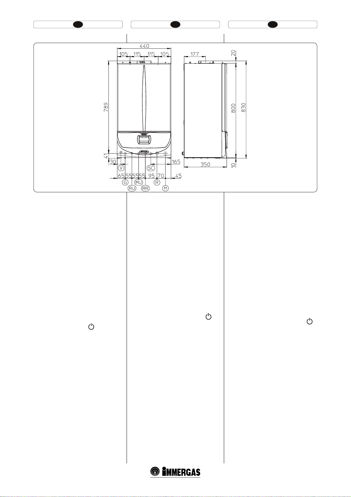
1.2 FŐBB MÉRETEK.
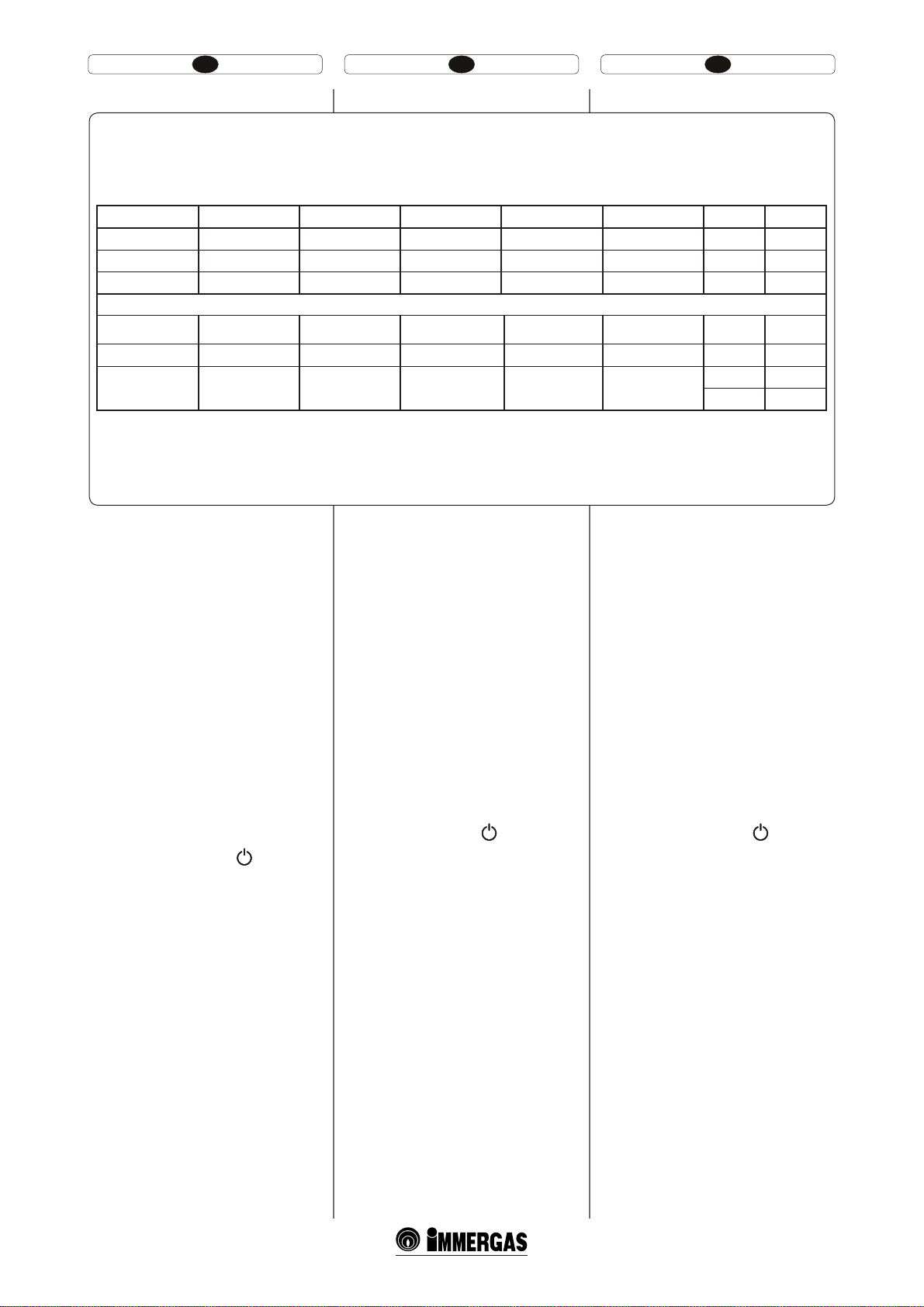
PL TR CZ HU RO
Wysokość Boy Výška Magasság Înălţime Height 830
Szerokość En Šířka Szélesség Lăţime Width 440
Głębokość Derinlik Hloubka Mélység Adâncime Depth 350
PRZYŁĄCZA - BAĞLANTILAR - PŘÍPOJKY - CSATLAKOZÓK - MUFE - ATTACHMENTS
GAZ GAZ PLYN GÁZ GAZ GAS G 3/4” *
WODA SUYUN VODA VÍZ APĂ WATER RR 1/2”
INSTALACJA TESİSAT ZAŘÍZENÍ BERENDEZÉS INSTALAŢIE PLANT
* = a kazán egy 90°-os gázcsappal van ellátva,
3/4” csatlakozókkal és Ø18 mm-es csatlakozódarabbal.
Jelmagyarázat (1-2 ábra):
V - Elektromos kapcsolódás
G- Gázellátás
RU - Forraló egység visszatérése (opcionális)
MU - Forraló egység menete (opcionális)
RR - Berendezés utántöltése
SC - Páralecspódás kiürítése (minimális belső
átmérő Ø 13 mm)
R - Berendezés visszacsatlakoztatása
M - Berendezés kimeneteli vize
1.3 FAGYÁSGÁTLÓ VÉDELEM.
Minimális hőmérséklet -3°C. A kazán egy sor
olyan fagyálló funkcióval van ellátva, amelyek megengedik a szivattyú és az égő működését, amikor a
kazán belső vizének hőmérséklete 4°C alá süllyed.
A fagyásgátló működését pedig a következők
biztosítják:
- a kazán megfelelőképpen van kapcsolva az gáz-,
és a villanyhálózathoz;
- a kazán folyamatos ellátású;
- a kazán nincs stand-by-ban (
- a kazán nincs begyújtási zár alatt (2.6 bekezd);
- a kazán fő összetevő részeiben nincs üzemzavar.
Ezekkel a feltételekkel a kazán védett a fagy ellen
–3°C környezeti hőmérsékletig.
Minimális hőmérséklet -15°C. Ha a kazán egy
olyan helyre van felszerelve, ahol a hőmérséklet
-3°C alá süllyed vagy, ha nincs gázellátás, vagy a
kazán zárásblokkálással működik, a berendezés
befagyhat.
A befagyás veszélyét elkerülendő, kövesse a következő
útmutatásokat:
- Védje a fűtési hálózatot jó márkájú fagyálló folyadék bevitelével a hálózatba (fűtőberendezések
számára valót), pontosan követve a kazán gyártójának utasításait annak tekintetében, hogy
mennyi a felhasználandó folyadék kellő százaléka, a minimális hőmérséklet függvényében,
amelytől a berendezést védeni kívánja.
A kazánt alkotó anyagok ellenállnak az etil-glikogén
és propilén alapú fagyálló folyadékoknak.
A tartósság és az esetenkénti zománcozás tekintetében kövesse a gyártó utasításait.
)
1.2 DIMENSIUNI PRINCIPALE .
* = centrala este dotată cu un robinet de gaz
la 90° cu mufe 3/4” şi racord Ø18 mm.
Legenda (Fig. 1-2):
V - Racord electric
G - Alimentare gaz
RU - Retur unitate erbător (opţional)
MU - Tur unitate erbător (opţional)
RR - Reumplere instalaţie
SC - Evacuare condens (diametru intern minim
Ø 13 mm)
R - Retur instalaţie
M - Tur instalaţie
1.3 PROTECŢIE ANTIÎNGHEŢ.
Temper atura Minimă -3°C. Centrala este dotată de
serie cu o funcţie antigel ce pune în funcţie pompa
şi arzătorul când temperatura apei în interiorul
centralei coboară sub 4°C.
Funcţia anti-îngheţ este însă asigurată doar dacă:
- centrala este racordată corect la circuitele de
alimentare cu gaz şi electrică;
- centrala este alimentată în mod constant;
- centrala nu e în stand-by (
- centrala nu este în stare de blocare datorată
nepornirii (vezi paragr.2.6);
- componentele esenţiale ale centralei nu sunt
defecte.
În aceste condiţii, centrala este protejată împotriva
îngheţului până la o temperatură a mediului de -3°C.
Temperatura minimă -15°C. În cazul în care centrala este instalată într-un loc în care temperatura
coboară sub -3°C şi atunci când lipseşte alimentarea
cu gaz sau centrala intră în stare de blocare datorată
nepornirii, este posibil să se ajungă la îngheţarea
aparatului.
Pentru a evita riscul de îngheţare, respectaţi
următoarele instrucţiuni
- Protejaţi circuitul de încălzire contra gerului
introducând în acest circuit un lichid antigel
(specic instalaţiilor de încălzire) cea mai bună
marcă, respectând scrupulos instrucţiunile fabricantului în ceea ce priveşte procentajul necesar
comparativ cu temperatura minimă la care se
doreşte păstrarea instalaţiei.
Materialele cu care sunt realizate centralele, rezistă
la lichide antigel pe bază de glicoli de etilenă şi
propilen.
Pentru durată şi eventuala dezmembrare, respectaţi
indicaţiile furnizorului.
)
1.2 MAIN DIMENSIONS.
IE
* = the boiler has gas valve at 90° with 3/4”
attachments and Ø18 mm. connections.
Key (Fig. 1-2):
V - Electrical connection
G - Gas connection
RU - Storage unit return (optional)
MU - Storage unit delivery (optional)
RR - System lling
SC - Condensate drain (minimum internal
diameter Ø 13 mm)
R - System return
M - System delivery
1.3 ANTIFREEZE PROTECTION.
Minimum temperature -3°C. e boiler comes
standard with an antifreeze function that activates
the pump and burner when the system water temperature in the boiler falls below 4°C.
e antifreeze function is only guaranteed if:
- the boiler is correctly connected to gas and
electricity power supply circuits;
- the boiler is powered constantly;
- the boiler is not in stand-by (
- the boiler is not in no ignition block (parag.
2.6);
- the boiler essential components are not faulty.
In these conditions the boiler is protected against
freezing to an environmental temperature of -3°C.
Minimum temperature -15°C. If the boiler is installed in a place where the temperature falls below
-3°C and in the event there is no gas, or the boiler
goes into ignition block, the appliance may freeze.
To prevent the risk of freezing follow the instructions below:
- Protect the heating circuit from freezing by
introducing a good quality anti/freeze liquid
(specically for heating systems), carefully following the manufacturer’s instructions regarding
the percentage necessary with respect to the
minimum temperature required for preserving
the system.
e materials the boilers are made from are resistant to ethylene and propylene glycol/based anti/
freeze liquids.
For life and possible disposal, follow the supplier’s
instructions.
(mm)
R 3/4”
M 3/4”
1-3
)
9
Page 7

HU IERO
- Védje a fagy ellen a berendezés utántöltő rendszerét és a kondenz kiürítő szifont a kérésre adott
kiegészítő használatával (fagyásgátló készlet),
amely egy villanyellenállásból, az ehhez tartozó
vezetékekből és egy távvezérlésű termosztátból
áll (olvassa el figyelmesen az összeszerelési
utasításokat, amelyek a kiegészítő készlethez
tartoznak).
A fagyásgátló védelem a kazán befagyása ellen
ilymódon akkor biztosítható, amennyiben:
- a kazán megfelelőképpen van kapcsolva az gáz-,
és a villanyhálózathoz;
- a fagyásgátló készlet elemeiben nincs üzemzavar.
Ezekkel a feltételekkel a kazán védett a fagy ellen
-15°C környezeti hőmérsékletig.
A garancia fenntartásának érdekében ki vannak zárva az elektromos áram megszakítása és az előbbiek
be nem tartása okozta károk.
Megj.: amennyiben a kazánt olyan helyekre szereli
be, ahol a hőmérséklet 0°C alá süllyed, a csatlakoztató csöveket szigetelni kell.
Az egető egységben a víz (ha van) nem védett a fagy
ellen, amennyiben a kazán ki van kapcsolva.
1.4 CSATLAKOZÁSOK.
Gázcsatlakozás (II
Kazánjainkat földgáz- (G20) és GPL-gáz üzemre terveztük. A csatlakozó gázcső átmérője ugyanakkora
vagy nagyobb legyen, mint a kazán 3/4”G csatlakozó
eleme. A gázhálózatra való csatlakoztatás előtt gondosan meg kell tisztítani a gázt szállító csőrendszer
belsejét az esetleges szennyeződésektől, mivel ezek
veszélyeztethetik a kazán megfelelő működését.
Ellenőrizni kell továbbá, hogy a rendelkezésre álló
gázfajta megegyezik-e azzal, amelyre a kazán be
van állítva (lásd a kazánon elhelyezett adattáblát).
Ha nem, a kazánt át kell állítani a rendelkezésre álló
más gázfajtára (lásd a készülék másféle gázüzemre
való átállítására vonatkozó részt). Ezen kívül fontos, a (földgáz vagy GPL gáz) hálózati dinamikus
nyomásának ellenőrzése, amelyről a kazán üzemelni
fog. Az elégtelen nyomás kihathat a fűtőkészülék
teljesítményére, ezáltal kellemetlenséget okozhat
a felhasználónak.
Ellenőrizze, hogy a gázelzáró csap helyesen van-e
bekötve. A gázcsatlakozó cső méretének meg kell
felelnie az érvényes előírásoknak, hogy az égő gázellátása a legnagyobb teljesítményen való üzemelés
esetén is megfelelő legyen, illetve biztosítva legyen
a készülék hatásfoka (lásd a műszaki adatokat).
A csatlakozási rendszernek meg kell felelnie a
szabványok előírásainak.
A fűtőgáz minősége. A készüléket
szennyeződésmentes fűtőgázzal való üzemelésre
tervezték, ellenkező esetben célszerű megfelelő
szűrőelemet beiktatni a készülék elé, hogy a
fűtőanyag kellően tiszta legyen.
Gáztárolók (GPL-gáz tartályról való üzemeltetés
esetén).
- Előfordulhat, hogy az újonnan létesített GPLgáz tartályok nyomokban inert gázt (nitrogént)
tartalmaznak, amely csökkenti a készülékbe jutó
gázkeverék fűtőértékét és ezáltal rendellenes
működést okozhat.
- A GPL gázkeverék összetételéből fakadóan
előfordulhat, hogy a tárolás során a keverék alkotóelemei egymás fölé rétegződnek. Ez megváltoztathatja a készülékbe jutó keverék fűtőértékét
és ezáltal befolyásolja annak hatásfokát.
kategóriájú készülék).
2H3B/P
Hidraulikus csatlakozás.
Figyelem: A hidraulikus hálózatra való csatlakozta-
tás előtt gondosan át kell mosni a víz- és fűtési rendszer belsejét (csövek, melegítők, stb.) erre a célra
szolgáló maró- vagy vízkőoldószerrel, mely képes
eltávolítani az esetleges szennyeződéseket, amelyek
veszélyeztethetik a kazán megfelelő működését.
A fűtőberendezésben a lerakódások,
mészkőlerakódások és rozsda keletkezésének
elkerülése végett be kell tartani a jogzsabályban
előírt előírásokat, amelyek a civil használatú
hőberendezésekben a vízkezelésre vonatkoznak.
- Protejaţi împotriva gerului circuitul de umplere instalaţie şi sifonul de evacuare a apei de
condensare utilizând un accesoriu furnizabil la
cerere (kit antigel) compus dintr-o rezistenţă
electrică, din cablajul corespunzător şi dintr-un
termostat de comandă (citiţi atent instrucţiunile
pentru montare incluse în confecţiunea kitului
accesoriu).
Protecţia împotriva îngheţării centralei este în acest
fel asigurată doar dacă:
- centrala este corect racordată la circuitul de alimentare electrică şi alimentată;
- Componentele kitului antigel nu sunt distruse.
În aceste condiţii centrala este protejată contra
îngheţului până la o temperatura de -15°C.
Pentru ecienţa garanţiei sunt excluse daunele ce
rezultă din întreruperea furnizării energiei electrice
şi din lipsa respectării celor precedente.
N.B.: în caz de instalare a centralei în locuri unde
temperatura coboară sub 0°C se solicită izolarea
tuburilor de racord.
Atunci când centrala este oprită apa din interiorul
erbătorului (dacă e prezentă) nu e protejată împotriva gerului.
1.4 RACORDURI.
Racord gaz (Aparat categoria II
Centralele noastre sunt construite pentru a
funcţiona cu gaz metan (G20) şi GPL. Conductele
de alimentare trebuie să e egale sau mai mari faţă
de racordul centralei 3/4”G. Înainte de a efectua
racordul la gaz trebuie să efectuaţi o curăţare
internă a tuturor conductelor instalaţiei de aducţie
a combustibilului pentru eliminarea eventualelor
reziduuri ce ar putea compromite buna funcţionare
a cazanului. Mai trebuie să se controleze ca gazul
distribuit să corespundă cu cel pentru care a
fost prevăzută centrala (vezi plăcuţa date de pe
centrală). Dacă diferă este necesar să interveniţi
asupra centralei pentru adaptarea la alt tip de gaz
(vezi conversiunea aparatelor în caz de schimb gaz).
E important să mai vericaţi presiunea dinamică
din reţea (metan sau GPL) care se va utiliza pentru
alimentarea centralei, întrucât dacă e insucientă
poate avea inuenţă asupra puterii generatorului
provocând neplăceri utilizatorului.
Asiguraţi-vă ca racordul robinetului de gaz să
se efectueze corect. Ţeava de aducţie a gazului
combustibil trebuie să e dimensionată adecvat în
baza normelor în vigoare pentru a garanta puterea
corectă a gazului în arzător şi în condiţiile de putere
maximă a generatorului şi să garanteze prestaţiile
aparatului (date tehnice). Sistemul de articulare
trebuie să e conform cu normele.
Calitatea gazului combustibil. Aparatul a fost
proiectat p entru a funcţion a cu gaz combustibil f ără
impurităţi; în caz contrar, este nevoie să introduceţi
ltre adecvate în amonte faţă de aparat pentru a
reface puritatea combustibilului.
Rezervoare de stocare (în caz de alimentare din
depozit de GPL).
- Se poate întâmpla ca noile rezervoare de stocare
GPL să conţină reziduuri de gaz inert (azot)
ce sărăcesc amestecul distribuit aparatului
cauzându-i funcţionări anormale.
- Din cauza compoziţiei amestecului GPL poate
apărea în timpul perioadei de stocare în rezervoare o straticare a componentelor amestecului.
Acest lucru poate cauza o variaţie a puterii
calorice a amestecului distribuit aparatului cu
variaţia prestaţiilor ulterioare ale acestuia.
2H3B/P
).
Racord hidraulic.
Atenţie: înainte de a efectua racordurile centralei
pentru a nu pierde garanţia privind modulul de
condensare spălaţi bine instalaţia termică (ţevi,
corpuri ce se încălzesc etc.) cu decapanţi adecvaţi
sau produse pentru eliminarea incrustaţiilor în
măsură să elimine eventualele reziduuri ce ar putea
compromite buna funcţionare a centralei.
Pentru a evita depunerile, incrustaţiile şi coroziunile
în instalaţia de încălzire, trebuie respectate prescrierile normei, privind tratarea apei în instalaţiile
termice cu utilizare civilă.
- Protect the lling circuit and condensate drain
trap against freezing by using an accessory that
is supplied on request (antifreeze kit) comprising
two electric heating elements, the relevant cables
and a control thermostat (carefully read the installation instructions contained in the accessory
kit pack).
Boiler anti-freezing protection is thus ensured
only if:
- the boiler is correctly connected to gas and electricity power supply circuits and powered;
- the anti-freezing kit components are ecient.
In these conditions the boiler is protected against
freezing to temperature of -15°C.
e warranty does not cover damage due to interruption of the electrical power supply and noncompliance with that given on the previously.
N.B.: if the boiler is installed in places where the
temperature falls below 0°C the attachment pipes
must be insulated.
e water inside the storage unit (if present) is not
protected from freezing when the boiler is o.
1.4 ATTACHMENTS.
Gas connection (Appliance category II
Our boilers are designed to operate with methane
gas (G20) and LPG. Supply pipes must be the same
as or larger than the 3/4”G boiler tting. Before
connecting the gas line, carefully clean inside all
the fuel feed system pipes to remove any residue
that could impair boiler eciency. Also make sure
the gas corresponds to that for which the boiler is
prepared (see boiler data-plate). If dierent, the
appliance must be converted for operation with
the other type of gas (see converting appliance for
other gas types). e dynamic gas supply (methane
or LPG) pressure must also be checked according to
the type used in the boiler, as insucient levels can
reduce generator output and cause malfunctions.
Ensure correct gas cock connection. e gas supply
pipe must be suitably dimensioned according to
current regulations in order to guarantee correct
gas ow to the boiler even in conditions of max.
generator output and to guarantee appliance efciency (technical specications). e coupling
system must conform to standards.
Combustible gas quality. e appliance has been
designed to operate with gas free of impurities;
otherwise it is advisable to t special lters upstream
from the appliance to restore the purity of the gas.
Storage tanks (in case of supply from LPG
depot).
- New LPG storage tanks may contain residual
inert gases (nitrogen) that degrade the mixture
delivered to the appliance casing functioning
anomalies.
- Due to the composition of the LPG mixture,
layering of the mixture components may occur
during the period of storage in the tanks. is
can cause a variation in the heating power of
the mixture delivered to the appliance, with
subsequent change in its performance.
2H3B/P
).
Hydraulic attachment.
Important: In order not to void the warranty before
making the boiler connections, carefully clean the
heating system (pipes, radiators, etc.) with special
pickling or de-scaling products to remove any
deposits that could compromise correct boiler
operation.
In order to avoid scaling in the heating system,
the provisions given in the regulations on water
treatment in heating systems for civil use must
be respected.
11
Page 8
HU IERO
A csatlakozásokat az észszerűségi szabályok szerint,
a kazán csatlakoztatási sablonjának alkalmazásával
kell elvégezni. A kazán biztonsági vízszelepét tölcséres lefolyóvezetékbe kell bekötni. Ellenkező esetben
a gyártó nem felel a működésbe lépő szelepen
keresztül kiömlő víz okozta károkért.
Kondenz kiürítése. A berendezés által termelt kondenz kiürítése végett csatlakoztassa a berendezést a
szennyvízcsatornarendszerhez a megfelelő, a savas
kondenznek ellenálló csövekkel, amelyek belseje
legalább Ø 13 mm.A szennyvízcsatornarendszerhez
csatlakozó berendezést a kazánhoz olymódon kell
csatlakoztatni, hogy a belsejében levő folyadék befagyása elkerülhető legyen. A berendezés bekapcsolása előtt ellenőrizze, hogy a kondenzet a megfelelő
módon ki lehet engedni. Kövesse ugyanakkor az
érvényben levő nemzeti és helyi jogszabályokat,
amelyek a szennyvízkiürítésre vonatkoznak.
Elektromos csatlakoztatás. Az “Victrix Superior
kW X” kazán érintésvédelmi kategóriája a készülék
egésze tekintetében IPX5D. A készülék elektromos
szempontból csak akkor biztonságos, ha az érvényes
biztonsági előírásoknak megfelelő módon le van földelve, az előrt biztonsági szabványoknak megfelelő
módon alkalmazva.
Figyelem: az Immergas S.p.A. nem vállal felelősséget
a kazán földelésének elmulasztásából és az ide vonatkozó szabványok be nem tartásából eredő személyi
vagy dologi károk miatt.
Ellenőrizni kell továbbá, hogy az elektromos fogyasztói hálózat eleget tudjon tenni a kazán adattábláján
feltüntetett maximális felvett teljesítménynek.A
kazánokat X típusú speciális, villásdugó nélküli
kábellel szállítjuk. A kábelt 230V ±10% / 50Hz
tápfeszültségű elektromos hálózatra kell csatlakoztatni, az L-N fázis és a földelés
lembevételével. A vezetékre egypólusú leválasztókapcsolót kell beiktatni, amelynek III osztályú
túlfeszültséggel kategóriával kell rendelkeznie.
A tápkábel cseréjét csak szakember (például az
Immergas szakszervíz munkatársa) végezheti el. A
tápkábelt az alábbiakban leirt módon kell vezetni.
A szabályozó kártyán található hálózati olvadó
biztosítékok cseréje esetén 3,15A-es gyors biztosítékot használjunk. A készülék általános elektromos bekötéséhez tilos adaptert, elosztót vagy
hosszabbítót használni.
1.5 TÁVVEZÉRLŐK ÉS BEPROGRAMÁL
HATÓ SZOBA TERMOSZTÁT VÁLA
SZTHATÓ.
A kazán vezérlésén gyárilag elő van készítve a programozható szoba termosztátok és a külső szonda
csatlakoztatásának lehetősége.
Ezeket a kiegészítőket az Immergas a kazántól
külön, megrendelésre szállítja.
Valamennyi Immergas programozható termosztát 2
eres vezetékkel köthető be. Olvassa el gyelmesen az
ezen kiegészítő tartozékokhoz csomagolt szerelési
és használati utasítást.
t #F,JLBQDTPMIBUØEJHJUÈMJTQSPHSBNP[IBUØT[PCB
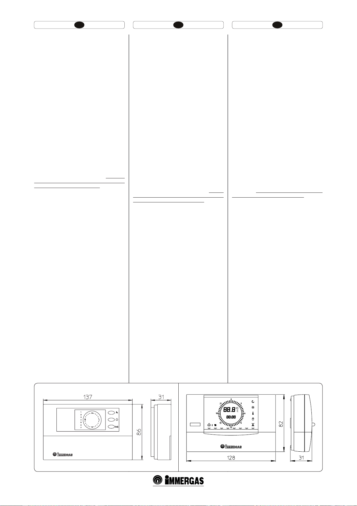
termosztát (1-5. ábra). A programozható szoba
termosztát lehetővé teszi:
- két különböző szobahőmérsékleti értéket: egy
nappali (komforthőmérséklet) és egy éjszakai
(csökkentett hőmérséklet) beállítását;
- akár négy különböző heti be- és kikapcsolási
program működtetését;
- az alábbi lehetőségek közül a kívánt üzemmód
kiválasztását:
tÈMMBOEØLPNGPSUIʩNÏSTÏLMFUʶGʶUÏTJNØE
tÈMMBOEØDTÚLLFOUFUUIʩNÏSTÏLMFUʶGʶUÏTJNØE
tÈMMBOEØGBHZWÏEFMNJ GʶUÏTJNØEÈMMÓUIBUØ
hőmérsékleten.
A szoba termosztát 2 db 1,5V-os LR6 típusú
alkáli elemmel működik;
, gye-
Racordurile hidraulice trebuie să e executate în
mod raţional folosind suporţii de prindere de pe
centrală. Evacuarea supapei de siguranţă a centralei
trebuie să e racordată la o pâlnie de evacuare. În
caz contrar, dacă supapa de evacuare funcţionează
invadând spaţiul, constructorul centralei nu va
responsabil.
Evacuare apă condensată. Pentru evacuarea apei
de condensare produsă de aparat, trebuie să vă
branşaţi la reţeaua de canalizare prin conducte
corespunzătoare rezistente la condensările acide,
având Ø intern de cel puţin 13 mm.Instalaţia de racordare a aparatului cu reţeaua de canalizare trebuie
efectuată astfel încât să evite congelarea lichidului
conţinut în ea. Înainte de punerea în funcţiune a
aparatului asiguraţi-vă că apa condensată poate
evacuată în mod corect. În plus trebuie respectată
norma în vigoare şi dispoziţiile naţionale şi locale
în vigoare pentru evacuarea apelor uzate.
Racord electric. Centrala “Victrix Superior kW
X” are pentru întreg aparatul un grad de protecţie
IPX5D. Siguranţa electrică a aparatului este atinsă
doar când acesta este perfect racordat la o instalaţie
eficientă de împământare, executată cum este
prevăzut de normele de siguranţă în vigoare.
Atenţie: Immergas S.p.A îşi declină orice responsabilitate pentru daunele provocate persoanelor
sau lucrurilor rezultate din lipsa racordului
împământării centralei şi de nerespectarea normelor de referinţă.
În plus vericaţi ca instalaţia electrică să e adecvată
puterii maxime absorbite de aparat indicată pe
plăcuţa de date de pe centrală. Centralele sunt
dotate cu cablu de alimentare special de tip ”X” fără
ştecher. Cablul de alimentare trebuie să e racordat
la o reţea de 230V ±10% / 50Hz respectând polaritatea L-N şi împământare
trebuie să e prevăzută o deconectare omnipolară
cu categorie de supratensiune de clasa III. În caz de
înlocuire a cablului de alimentare adresaţi-vă unui
tehnician abilitat (de exemplu Serviciul de Asistenţă
Tehnică Autorizat Immergas). Cablul de alimentare
trebuie să respecte traseul prestabilit.
În cazul în care trebuie să se înlocuiască siguranţa de
reţea pe placa de reglare, folosiţi o siguranţ ă de 3,15
A rapidă. Pentru alimentarea generală a aparatului
de la reţeaua electrică, nu este permisă folosirea de
adaptoare, prize multiple şi prelungitoar.
1.5 COMENZI CU ACŢIONARE DE LA
DISTANŢĂ ŞI CRONOTERMISTAŢI DE
AMBIENT OPŢIONAL.
Centrala este prevăzută pentru aplicarea
cronotermostaţilor de ambient sau a comenzilor
de la distanţă.
Aceste componente Immergas sunt disponibile
ca şi kituri separate ale centralei şi pot furnizate
la cerere.
Toţi cronotermostaţii Immergas pot legaţi cu
numai două re. Citiţi cu atenţie instrucţiunile
pentru montare şi utilizare conţinute în kitul
suplimentar.
t $SPOPUFSNPTUBUVMEJHJUBM 0O0GG 'JH
Cronotermostatul permite:
- programarea a două valori de temperatură
ambientală: una pentru zi (temperatura
confort) şi alta pentru noapte (temperatura
redusă);
- programarea până la patru programe
săptămânale diferite de pornire şi oprire;
- selecţionarea stării de funcţionare dorită între
diferitele alternative posibile:
tGVODʴJPOBSFBQFSNBOFOUʅÔOUFNQDPOGPSU
tGVODʴJPOBSFBQFSNBOFOUʅÔOUFNQSFEVTʅ
tGVODʴJPOBSFBQFSNBOFOUʅÔOUFNQBOUJÔOHIFʴ
reglabil.
Cronotermostatul este alimentat cu două baterii
de 1,5V tip LR 6 alcaline;
, spe această reţea
Water connections must be made in a rational way
using the couplings on the boiler template. e
boiler safety valve outlet must be connected to a
discharge funnel. Otherwise, the manufacturer
declines any responsibility in case of ooding if the
drain valve cuts in.
Condensate drain. To drain the condensate produced by the appliance, it is necessary to connect to
the drainage system by means of acid condensate
resistant pipes having an internal diameter of at least
13 mm. e system connecting the appliance to
the drainage system must be carried out in such a
way as to prevent freezing of the liquid contained
in it. Before appliance start-up, ensure that the
condensate can be correctly removed. Also, comply
with national and local regulations on discharging
waste waters.
Electrical connection: The “Victrix Superior
kW X” boiler has an IPX5D protection rating for
the entire appliance. Electrical safety of the unit
is reached when it is correctly connected to an
ecient earthing system as specied by current
safety standards.
Important: Immergas S.p.A. declines any responsibility for damage or physical injury caused by failure
to connect the boiler to an ecient earth system or
failure to comply with the reference standards.
Also ensure that the electrical installation corresponds to maximum absorbed power specications
as shown on the boiler data-plate. Boilers are
supplied complete with an “X” type power cable
without plug. The power supply cable must be
connected to a 230V ±10% / 50Hz mains supply
respecting L-N polarity and earth connection
, this network must also have a multi-pole circuit
breaker with class III over-voltage category. When
replacing the power supply cable, contact a qualied
technician (e.g. the Immergas Aer-Sales Technical
Assistance Service). e power cable must be laid
as shown.
In the event of mains fuse replacement on the control card, use a 3.15A quick-blow fuse. For the main
power supply to the appliance, never use adapters,
multiple sockets or extension leads.
1.5 REMOTE CONTROLS AND ROOM
CHRONOTHERMOSTATS OPTIO
NAL.
The boiler is prepared for application of room
chronothermostats or remote controls.
ese Immergas components are available as separate kits to the boiler and are supplied on request.
All Immergas chronothermostats are connected
with 2 wires only. C arefully read the user and assembly instructions contained in the accessory kit.
t 0O0ČEJHJUBMDISPOPUIFSNPTUBU'JHćF
chronothermostat allows:
- to set two room temperature values: one for
day (comfort temperature) and one for night
(lower temperature);
- to set up to four on/o dierential weekly
programs;
- selecting the required function mode from the
various possible alternatives:
tQFSNBOFOUGVODUJPOJOHJODPNGPSUUFNQ
tQFSNBOFOUPQFSBUJPOJOMPXFSUFNQ
tQFSNBOFOUGVODUJPOJOBEKVTUBCMFBOUJGSFF[F
temp.
e chronothermostat is powered by two 1.5V
LR 6 type alkaline batteries;
13
Page 9
PL CZTR
funkcjami opisanymi w poprzednim punkcie,
na kontrolę, a przede wszystkim na posiadanie
w zasięgu ręki, wszystkich ważnych informacji
dotyczących pracy urządzenia i instalacji
cieplnej z możliwością ingerencji w wygodny
sposób we wcześniej ustawione parametry, bez
konieczności przemieszczania się do miejsca,
gdzie zainstalowane jest urządzenie. Panel
wyposażony jest w funkcję samokontroli w celu
przedstawienia na wyświetlaczu ewentualnych
nieprawidłowości w pracy kotła. Klimatyczny
termostat czasowy wbudowany w zdalny
panel zezwala na dostosowanie temperatury
wyjściowej instalacji do faktycznych potrzeb
pomieszczenia do ogrzania, tak, aby otrzymać
pożądaną wartość temperatury otoczenia z
ekstremalną dokładnością i w konsekwencji z
wyraźną oszczędnością kosztów eksploatacji.
Termostat czasowy zasilany jest bezpośrednio
z kotła przy pomocy tych samych przewodów,
które służą do transmisji danych między kotłem
i termostatem czasowym.
Ważne: W przypadku, gdy instalacja podzielona jest na strefy przy pomocy odpowiedniego
zestawu CAR i Super CAR muszą zostać użyte
wyłączając funkcję termoregulacji klimatycznej,
czyli ustawiając go w trybie On/O.
Połączenie elektryczne CAR i Super CAR lub
termostat czasowy On/O (Opcja). Czynności
opisane poniżej mogą zostać przeprowadzone po
odcięciu napięcia od urządzenia. Ewentualny
termostat czasowy otoczenia On/O podłącza się
do zacisków 40 i 41 usuwając mostek X40 (Rys.
3-2). Upewnić się, że styk termostatu On/O jest
rodzaju “czystego” tzn., niezależny od napięcia sieci,
w przeciwnym razie karta elektroniczna regulacji
uległaby uszkodzeniu. Ewentualny CAR lub
Super CAR musi zostać podłączony przy pomocy
zacisków IN+ i IN- do zacisków 42 i 43 na karcie
elektronicznej (w kotle), usuwając mostek X40 i
uwzględniając biegunowość, (Rys. 3-2). Podłączeni
z błędną biegunowością, nawet jeśli nie uszkodzi
CAR, nie dopuści do jego funkcjonowania. Możliwe
jest podłączenie do kotła tylko jednego zdalnego
sterowania.
Ważne: W razie korzystania ze Zdalnego Sterowania Przyjaciel należy przygotować dwie osobne
linie według obowiązujących norm dotyczących
instalacji elektrycznych. Instalacja rurowa nigdy
nie może zostać wykorzystana jako uziemienie
instalacji elektrycznej lub telefonicznej. Upewnić
się więc, że tak nie jest, jeszcze przed podłączeniem
elektrycznym kotła.
Montaż z instalacją funkcjonującą o niskiej
temperaturze bezpośredniej. Kocioł może
bezpośrednio zasilać instalację o niskiej temperaturze wpływając na parametr “P66” (Parag. 3.8) i
ustawiając zakres regulacji temperatury wyjściowej
“P66/A” i “P66/B”. W takiej sytuacji wskazane
jest wprowadzenie w serii do zasilania kotła, zabezpieczenie złożone z termostatu o maksymalnej
temperaturze 60°C. Termostat musi być umieszczony na rurze wyjściowej instalacji w odległości
przynajmniej 2 metrów od kotła.
Dost Uzaktan KUmanda (CAR) (Şekil 1-6) ve
Süğer Dost Uzaktan Kumanda (Süper CAR)
(Şekil 1-7) olup, her ikisinde de klimatik
kronometrik termostat mevcuttur. Kronometrik termostat panelleri, yukarıda belirtilen
olanakların yanı sıra, kullanıcı için cihaz ile
termik devrenin tüm işlevlerinin her an için el
altında ve kontrol edilebilir olmasını sağlamanın
yanı sıra daha önceden ayarlanmış parametreler
üzerinde cihazın monte edilmiş olduğu mekana
gitmeksizin arzulanan ayarların yapılabilmesine
imkan tanır. Ayrıca panelde otokontrol yöntemiyle kombide oluşabilecek muhtemel arıza
hallerinin göstergede görüntülenebilmesine
olanak sağlayan bir düzenek de bulunmaktadır.
Uzaktan kumandada yer alan klimatik kronometrik termostat ısıtılması gereken ortamın gerçek
gereksinimlerinin belirlenerek gerekli ısının
yayılmasını sağlar, bu suretle de ortamda arzulanan ısının sabit kalmasının yanı sıra işletme
maliyetlerinde tasarruf sağlanmasına katkıda
bulunur. Kronometrik termostat, kombi ile
kronometrik termostat arasında veri aktarımını
sağlayan 2 kablo aracılığıyla doğrudan doğruya
kombi cihazından beslenir.
Önemli : Tesisatın “CAR” ve “Süper CAR” set
vasıtasıyla farklı bölgelere ayrılmış olması halinde
klimatik termik ayar devre dışı bırakılarak yani
On/Off modu ayarlanarak kullanılması gerekmektedir.
CAR, Süper CAR ve kronometrik termostat On/
O elektronik bağlantısı (opsiyonel). Aşağıda
belirtilen işlemlerin cihazdan elektrik girişinin kesilmesinden sonra yapılması gerekmektedir. Mu htemel
ortam kronometrik termostatı On/O, X40 köprüsü kesilerek 40 ve 41 slotlara bağlanır (şekil 3-2).
On/O termostat slotunun “temiz” tipte olmasına
yani ağ geriliminden bağımsız olmasına dikkat
ediniz, böyle olmaması halinde elektronik ayar
kartı hasar görebilir. Muhtemel CAR veyahut da
Süper CAR IN+ ve IN- slotlarının 42 ve 43 slotlara
bağlanması ile ve elektronik kartta (kombide) yer
alan X40 köprüsünün iptali suretiyle ve de doğru
kutuplara gelmesine dikkat edilerek yapılır (Şekil
3-2). Hatalı kutuplara bağlantı yapılması halinde
CAR hasar görmemekle birlikte işlevini de yerine
getiremez. Kombi cihazına tek bir uzaktan kumanda cihazının bağlanması kabildir.
Önemli : CAR kullanılması halinde elektrik
tesisatları konusundaki yürürlükte bulunan yasal
düzenlemeler gereğince iki ayrı hat bulundurulması
zorunluluğu mevcuttur. Kombinin hiçbir boru
veyahut da hortumunun elektrik veyahut da telefon toprak hattı olarak kullanılmasına müsaade
edilemez. Bu nedenle buna benzer bir durumun
oluşmadığını kombinin elektrik bağlantılarını
yapmadan evvel kontrol ediniz.
Doğrudan düşük ısı ile çalışan tesisatla montaj.
Kombi, “P66” parametresi üzerinde müdahalede
bulunmak suretiyle (Paragraf 3.8) ve gönderim ısı
ayar aralığını “P66/A” ve “P66/B” olarak ayarlayarak düşük ısılı bir tesisatı doğrudan besleyebilir.
Bu durumda, kombi girişine seri olarak, sınır ısısı
60°C derece olan bir termostat vasıtasıyla emniyet
tertibatı takılması gerekmektedir.
Termostatın kombiden en azından 2 metre uzak bir
noktada tesisat gönderim borusu üzerine takılması
gerekmektedir
t ,EJTQP[JDJKTPVEWBUZQZEÈMLPWâDIPWMBEBʊʹ
Comando Amico Remoto (CAR) (Obr. 1-6)
a Super Amico Comando Remoto (Super
CAR) (Obr. 1-7). Oba mají funkci klimatických časových termostatů. Panely časových
termostatů umožňují uživateli kromě výše
uvedených funkci mít pod kontrolou a
především po ruce všechny důležité informace týkající se funkce přístroje a tepelného
zařízení, díky čemuž je možné pohodlně
zasahovat do dříve nastavených parametrů
bez nutnosti přemísťovat se na místo, kde je
přístroj instalován. Panel je opatřen autodiagnostickou funkcí, která zobrazuje na displeji
případné poruchy funkce kotle. Klimatický
časový termostat zabudovaný v dálkovém
panelu umožňuje přizpůsobit v ýstupní teplotu
zařízení skutečné potřebě prostředí, které je
třeba vytápět. Tak bude možné dosáhnout
požadované teploty prostředí s maximální
přesností a tedy s výraznou úsporou na
provozních nákladech. Časový termostat je
napájen přímo z kotle dvěma vodiči, které
slouží zároveň k přenosu dat mezi kotlem a
časovým termostatem.
Důležité: V případě, že je zařízení rozdělené do
zón pomocí příslušné soupravy, musí se na CAR
a Super CAR vyřadit funkce klimatické termoregulace, nebo ho nastavit do režimu Zap/Vyp.
Elektrické připojení dálkových ovladačů CAR,
Super CAR nebo časového termostatu Zap/Vyp
(volitelně). Níže uvedené operace se provádějí
po odpojení zařízení od elektrické sítě. Případný
pokojový časový termostat Zap/Vyp se případně
připojí ke svorkám 40 a 41 po odstranění
přemostění X40 (Obr. 3-2). Ujistěte se, že kontakt termostatu Zap/Vyp je „čistého typu“, tedy
nezávislý na síťovém napětí. V opačném případě
by se poškodila elektronická regulační karta.
CAR nebo Super CAR je případně nutné připojit
pomocí svorek IN+ a IN- ke svorkám 42 a 43 po
odstranění přemostění X40 na elektronické desce
(v kotli), přičemž je třeba respektovat polaritu
(Obr. 3-2). Ačkoliv připojení s nesprávnou polaritou ovladač CAR nepoškodí, ale ten nebude
fungovat. Ke kotli je možné připojit pouze jeden
dálkový ovladač.
Důležité: V případě použití dálkového ovládání
Comando Amico Remoto je uživatel povinen
zajistit dvě oddělená vedení podle platných
norem vztahujících se na elektrická zařízení.
Veškerá potrubí nesmí být nikdy použita jako
uzemnění elektrického nebo telefonického
zařízení. Ujistěte se, aby k tomu nedošlo před
elektrickým zapojením kotle.
Instalace v případě zařízení pracujícího při
nízké přímé teplotě. Kotel může zásobovat
přímo nízkoteplotní systém po zásahu do parametru “P66” (Odst. 3.8) a nastavení regulačního
teplotního rozsahu na náběhu “P66/A” a “P66/B”.
V takovém případě je vhodné zařadit ke kotli
sériově pojistku tvořenou termostatem s limitní teplotou 60°C. Termostat musí být umístěn
na výstupním potrubí zařízení ve vzdálenosti
alespoň 2 metry od kotle.
1-5
1-6
14
Page 10
HU IERO
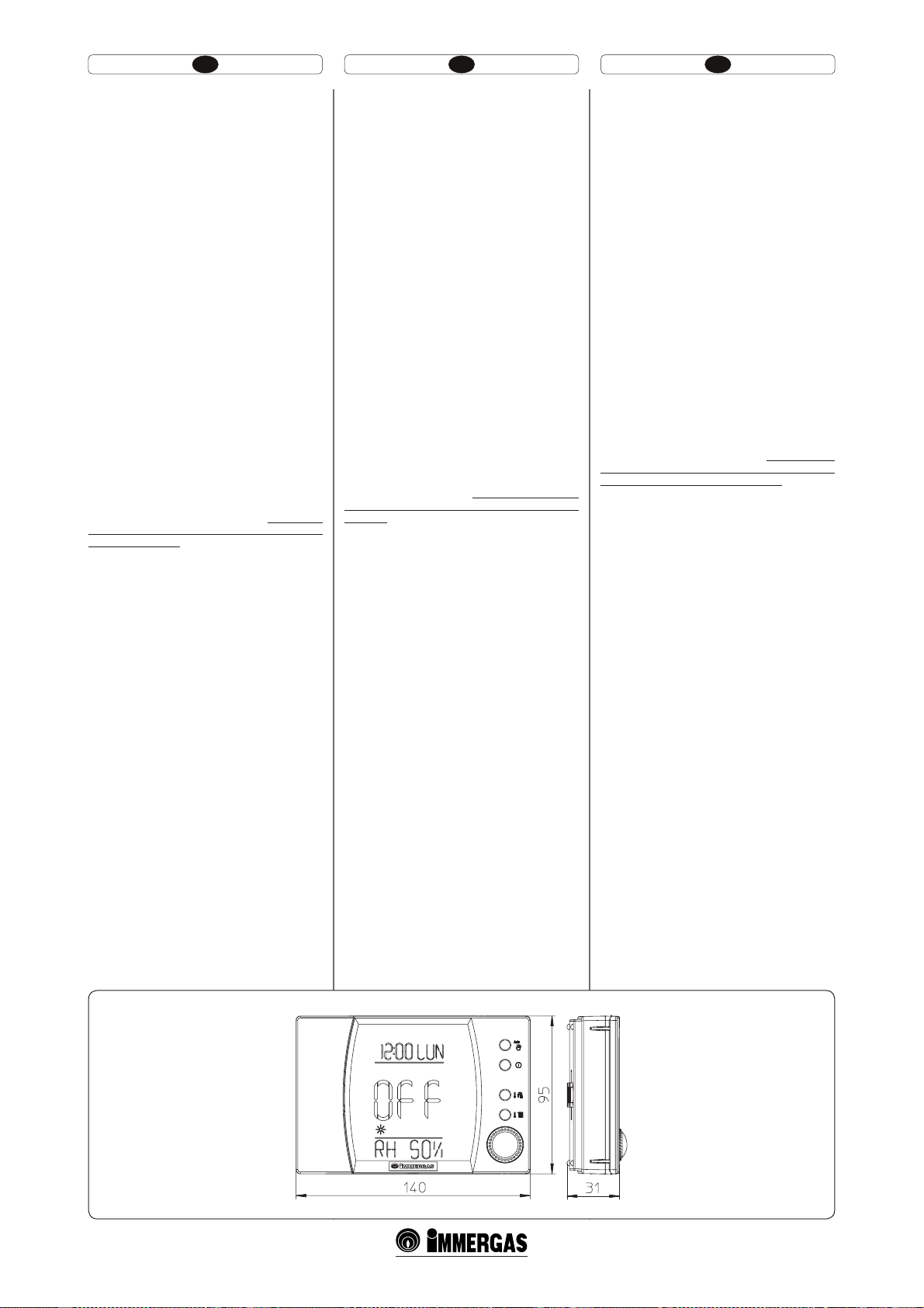
t ,ÏUGBKUBUÈWWF[ÏSMʩLBQIBUØ"NJDP5ÈWWF[ÏSMʩ
(CAR) (1-6. ábra) és Super Távvezérlő (Super
CAR) (1-7. ábra), mindegyik időjárásfüggő
programozható szoba termosztát működéssel.
A távvezérlő egység az előző pontban foglaltakon túl lehetőséget ad a felhasználónak, hogy
folyamatosan és a legnagyobb kényelemben
ellenőrizze a készülék és a fűtési rendszer
működésére vonatkozó valamennyi lényeges
információt, illetve ugyanilyen kényelmesen
megváltoztassa a korábban beállított paramétereket anélkül, hogy oda kellene fáradnia a
készülékhez. A távvezérlő egység öndiagnosztikai funkcióval is rendelkezik, így a kijelzőről
leolvashatók a kazán működése során előforduló
esetleges rendellenességek. A távvezérlő panelbe
épített programozható szoba termosztát lehetővé
teszi, hogy az előremenő fűtési hőmérsékletet
a fűtendő helyiség tényleges hőszükségletéhez
igazítsuk, így a kívánt hőmérsékleti értéket
a berendezés rendkívül pontosan biztosítja,
ezáltal pedig nyilvánvalóan csökken az üzemeltetési költség. A programozható termosztát
közvetlenül a kazántól kapja a tápfeszültséget
ugyanazon a 2 eres kábelen, amely a kazán és a
termosztát közti adatátvitelre is szolgál.
Fontos: Az arra szolgáló készlet segítségével
zónákra osztott berendezés esetében a CAR-t úgy
kell használni, hogy kiiktatja az időjárásfüggő
hőmérsékletszabályozó funkciót, azaz Be/Ki
üzemmódra állítja.
Amico Távvezérlő, Super Távvezérlő vagy Ki/Be
kapcsolható programozható szoba termosztát
elektromos csatlakoztatása (opció). Az alábbia-
kban leírt műveletek elvégzése előtt a készüléket
áramtalanítani kell. Az esetleges Ki/Be kapcsolós
szoba termosztátot a 40-es és 41-es sorkapocsra
kell bekötni, az X40-es átkötés megszűntetésével
(3-2. ábra). Meg kell bizonyosodni róla, hogy a
Ki/Be kapcsolós termosztát érintkezése “terhelés
mentes”, vagyis hálózati feszültségtől független
legyen, ellenkező esetben károsodik az elektronikus
szabályozó kártya. Az esetleges Amico távvezérlő
egységet az IN+ és IN sorkapcsok segítségével a
kazánban található elektronikus kártya 42-es és
43-as sorkapcsára kell bekötni az X40-es átkötés
megszűntetésével, a polaritások gyelembe vételével
(3-2. ábra). A fázis-nulla felcserélése nem károsítja
az Amico távvezérlő egységet, de nem teszi lehetővé
a működését. Csak egy távvezérlő egységet lehet a
kazánra csatlakoztatni.
Fontos! Amico Távvezérlő egység alkalmazása
esetén az elektromos hálózatokra vonatkozó hatályos előírások értelmében kötelező két különálló
áramkört létesíteni. A kazán csöveit soha nem
szabad elektromos vagy telefonvezeték földelésére
használni, és e tilalom betartását a kazán elektromos
bekötése előtt ellenőrizni is kell.
Beszerelés a közvetlenül, alacsony hőmérséklettel
működő berendezéssel. A kazán közvetlenül láthat
el egy alacsony hőmérsékletű berendezést a “P66”
gomb kezelése álta (3.8 bekezd.) és a “P66/A” és
“P66/B” szállító hőmérséklet szabályozási sávját.
Ebben az esetben gyárilag be kell szerelni az ellátáshoz és a kazánba egy olyan biztonsági egységet,
amely legtöbb 60°C-os hőmérséklettel rendelkező
termosztátból áll. A termosztátot a berendezés
szállító csövére kell felszerelni, legalább 2 méter
távolságra a kazántól.
t 4VOUEJTQPOJCJMFUJQPMPHJJ EF DPNFO[J EF MB
distanţă: Comanda Amico Remoto (CAR)
(Fig.1-6) şi Super Comandă Amico Remoto
(super CAR) (Fig. 1-7) ambele cu funcţionare
de cronotermostaţi climatici. Panourile
cronotermostaţilor permit utilizatorului, în
afara funcţiilor ilustrate la punctul precedent, să
aibă sub control şi la îndemână toate informaţiile
importante privind funcţionarea aparatului şi
instalaţiei termice cu posibilitatea de a interveni
comod asupra parametrilor setaţi anterior fără
nevoia de a se deplasa în locul unde este instalat
aparatul. Panoul Comandă Amico Remoto este
dotat cu auto-diagnosticare pentru a vizualiza pe
display, eventualele anomalii de funcţionare ale
centralei. Cronotermostatul climatic încorporat
în panoul de la distanţă, permite ajustarea temperaturii de tur a instalaţiei la necesităţile efective
ale ambientului care trebuie încălzit, pentru a
se obţine temperatura ambientală dorită, cu o
precizie deosebită şi cu o evidentă economisire
asupra costului de gestionare. Cronotermostatul
este alimentat direct de la centrală, prin intermediul aceloraşi 2 re care ajută la transmiterea
datelor între centrală şi cronotermostat.
Important: În cazul instalaţiei subdivizate în
zone prin intermediul kitului corespunzător CAR
şi Super CAR trebuie să fie utilizate excluzând
funcţia sa de termoreglare climatică sau setând
modalitatea On/O.
Racord electric CAR, Super CAR sau cronotermostat On/O (opţional).Operaţiunil e descrise în
continuare sunt efectuate după întreruperea tensiunii
la aparat. Eventualul cronotermostat mediu On/O
va legat la bornele 40 şi 41 eliminând puntea X40
(Fig. 3-2). Asiguraţi-vă că contactul termostatului
On/O este de tipul “curat” adică independent de
tensiunea din reţea, în caz contrar placa electronică
de reglare ar putea avaria. Eventuala CAR sau Super
CAR trebuie să e legate prin intermediul bornelor
IN+ şi IN- la bornele 42 şi 43 pe placa electronică
(în centrală) eliminând puntea X40 şi respectând
polaritatea, (Fig. 3-2). Legarea, cu polaritatea
greşită, chiar dacă nu ar defecta CAR, nu permite
funcţionarea acesteia. La centrală se poate racorda
doar o singură comandă de la distanţă.
Important: Este obligatoriu, în eventualitatea
utilizării Comenzii Amico Remoto să e predispuse
două linii, în conformitate cu normele în vigoare
existente, privind instalaţiile electrice. Toate ţevile
centralei nu trebuie să e niciodată utilizate ca prize
de împământare ale instalaţiei electrice sau telefonice. Asiguraţi-vă aşadar, că acest lucru nu se produce,
înainte de racordarea electrică a centralei.
Instalare cu aparat ce funcţionează la temperatură
joasă directă. Centrala poate alimenta direct o
instalaţie cu temperatura joasă acţionând asupra
parametrului “P66” (Parag. 3.8) şi setând intervalul
de reglare temperatură tur “P66/A” şi “P66/B”. În
această situaţie este necesar să se introducă în serie
la alimentare şi la centrală, o siguranţă constituită
dintr-un termostat având temperatura limită de
60°C. Termostatul trebuie să e poziţionat pe tubul
de tur instalaţie la o distanţă de cel puţin 2 metri
de la centrală.
t ćFSFBSFUXPUZQFTPGSFNPUFDPOUSPMTBWBJMBCMF
Remote Friend Control (RFC) (Fig. 1-6) and
Digital Remote Control (DRC) (Fig. 1-7) both
with room chronothermostat functioning. In
addition to the functions described in the previous point, the chronothermostat panels enable
the user to control all the important information
regarding operation of the appliance and the
heating system with the opportunity of easily
intervening on the previously set parameters
without having to go to the place where the
appliance is installed. e panel is provided
with self-diagnosis to display any boiler functioning anomalies. e climate chronothermostat
incorporated in the remote panel enables the
system delivery temperature to be adjusted to the
actual needs of the room being heated, in order
to obtain the desired room temperature with
extreme precision and therefore with evident
saving in running costs. e chronothermostat
is fed directly by the boiler by means of the same
2 wires used for the transmission of data between
boiler and chronothermostat.
Important: If the system is subdivided into zones
using the relevant kit the RFC and the Super RFC
must be used with its climate thermostat function
disabled, i.e. it must be set to On/O mode.
RFC, Super RFC or On/O chronothermostat
electrical connection (Optional). e operations
described below must be performed aer having
removed the voltage from the appliance. e even-
tual On/O environment chronothermostat must
be connected to clamps 40 and 41 eliminating
jumper X40 (Fig. 3-2). Make sure that the On/
O thermostat contact is of the “clean” type, i.e.
independent of the mains supply; otherwise the
electronic adjustment card would be damaged. e
eventual RFC or Super RFC must be connected by
means of terminals IN+ and IN- to terminals 42
and 43 on the circuit board, eliminating jumper
X40 and respecting polarity (Fig. 3-2). Connection
with the wrong polarity prevents functioning, but
without damaging the RFC e boiler can only be
connected to one remote control.
Important: If the Remote Friend Control is used,
arrange two separate lines in compliance with
current regulations regarding electrical systems.
Boiler pipes must never be used to earth the electric
or telephone lines. Ensure elimination of this risk
before making the boiler electrical connections.
Installation with system operating at direct low
temperature. e boiler can directly feed a low
temperature system by acting on parameter “P66”
(Par. 3.8) and setting the delivery temperature
adjustment range“P66/A” and “P66/B”. In this situation it is good practice to insert a safety device in
series with the power supply and boiler. is device
is made up from a thermostat with a temperature
limit of 60°C. e thermostat must be positioned
on the system delivery pipe at a distance of at least
2 metres from the boiler.
15
1-7
Page 11
PL CZTR
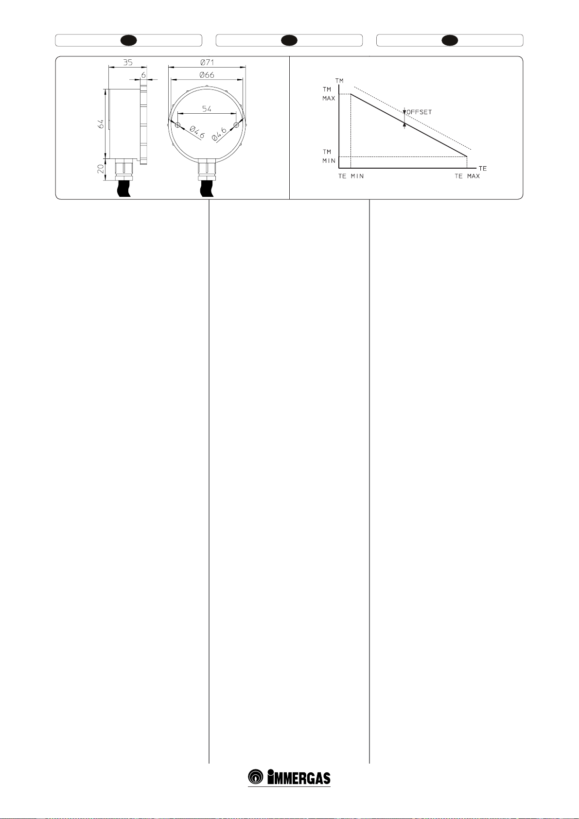
1.6 SONDA ZEWNĘTRZNA TEMPERATU
RY OPCJA .
Sonda ta (Rys. 1-8) może byż podłączona
bezpośrednio do instalacji elektrycznej kotła i
pozwala na automatyczne obniżenie maksymalnej
temperatury wyjściowej w chwili, gdy wzrasta temperatura zewnętrzna; pozwoli to na dostosowanie
ciepła dostarczanego do instalacji w zależności od
zmian temperatury zewnętrznej. Sonda zewnętrzna
reaguje zawsze, gdy podłączona, niezależnie
od obecności i rodzaju używanego termostatu
czasowego otoczenia i może pracować z termostatami czasowymi Immergas. Korelacja między
temperaturą wyjściową instalacji i temperaturą
zewnętrzną określona jest przez parametry ustawione na menu “M5” przy haśle “P66” według
krzywych przedstawionych w diagramie (Rys. 1-9).
Podłączenie elektryczne sondy zewnętrznej musi
odbyć się na zaciskach 38 i 39 na karcie elektronicznej kotła (Rys. 3-2).
1.7 SYSTEMY DYMNE IMMERGAS.
Firma Immergas, oddzielnie od kotłów dostarcza
różne rozwiązania do instalowania końcówek
zasysania powietrza i odprowadzania spalin, bez
których nie może funkcjonować.
Uwaga: kocioł musi zostać zainstalowany
wyłącznie z urządzeniem zasysania powietrza i
odprowadzania spalin na widoku z oryginalnego
materiału plastikowego Immergas “Seria Zielona”. Taki system dymny rozpoznawalny jest przez
odpowiedni znak identykac yjny i wyróżniający,
noszący informację: “tylko dla kotłów kondensacyjnych”. Rodzaje końcówek udostępnionych
przez Immergas to:
t $[ZOOJLJ0QPSVJPEQPXJBEBKʇDFJNEVHPʯDJ
Każdy komponent systemu dymnego posiadaCzynnik Oporu otrzymany po eksperymentalnych próbach i naniesiony w poniższej tabeli.
Czynnik Oporu pojedynczego komponentu
jest niezależny od rodzaju kotła, na kórym jest
zainstalowany i jest wielkością bezwymiarową.
Zależny jest natomiast od temperatury płynów,
które przepływają wewnątrz przewodu i zmienia
się wraz z użyciem przy zasysaniu powietrza
i odprowadzania spalin. Każdy pojedynczy
komponent posiada opór odpowiadający pewnej
długości w metrach rury o tym samym przekroju, tzw. długość ekwiwalentnąotrzymywaną
ze stosunku między odpowiednimi Czynnikami
Oporu. Wszystkie kotły mają maksymalny
Czynnik Oporu otrzymywany eksperymentalnie
równy 100. Maksymalny dopuszczalny Czynnik
Oporu odpowiada oporowi odnotowanemu
przy maksymalnej dopuszczalnej długości rur
każdej typologii Zestawu Końcówek. Wszystkie
te informacje pozwalają na przeprowadzenie
obliczeń w celu sprawdzenia możliwości różnych
konguracji systemu dymnego.
1-8
1.6 HARİCİ ISI SONDASI OPSİYONEL.
Bu sonda (Şekil 1-8) doğrudan doğruya kombi
cihazının elektrik tesisatına bağlanabilir olup, harici
ısının yükselmesi halinde kombi üretim ısısını otomatik olarak düşürmek suretiyle tesisatın çalışma
ısısını harici ortam ısısına göre ayarlar. Harici
sonda bağlı olduğu müddetçe kullanılan ortam
kronometrik termik ayarın türünden bağımsız
olarak İmmergas kronometrik termostat ile birlikte çalışabilir. Tesisatın gönderim ısısı ile harici
ısı arasındaki ilişki “M5” menüsünde “P66” adı
altında görülen diyagram eğrileri doğrultusunda
ayarlanmış olan parametrelere bağlıdır (şekil
1-9). Harici sondanın elektrik bağlantısı kombi
cihazındaki elektronik kart üzerindeki 38 ve 39
slotlarından sağlanır (şekil 3-2).
1.7 İMMERGAS BACA SİSTEMLERİ.
İmmergas, kombilerden ayrı olarak, kombinin
çalışması için elzem olan hava emiş ve duman
tahliye terminallerinin montajı için farklı çözümler sunar.
Dikkat : kombiler yalnızca İmmergas “Yeşil Seri”
plastikten mamul görülebilir bir şekilde takılac ak
olan hava emiş ve duman tahliye düzeneği ile
birlikte monte edilebilirler. Bu tahliye boru
tipleri aşağıdaki ibareyi taşıyan bir tanımlama
markasına haizdirler : “yalnızca yoğuşmalı kombiler için”. İmmergas tarafından sunulan terminal
tipleri şunlardır :
t &ʰEFʓFS.VLBWFNFUWF V[VOMVL GBLUÚSMFSJ
Tahliye borusunu oluşturan her bir parçanın
deneysel testlere istinaden ortaya çıkmış ve
bir sonraki tabloda belirtilmekte olan Mukavemet faktörü bulunmaktadır. Beher parçanın
Mukavemet Faktörü monte edildikleri kombi
tipinden bağımsız olup boyutsal olmayan bir hacimdir. Ancak, kanalın içerisinden geçen sıvının
ısısna bağlı olup, hava emiş ve duman tahliye
kullanımları arasındaki farka dikkat etmek gerekir. Beher münferit aksamın ayni çapta belli bir
uzunlukta boruya tekabül eden bir mukavemeti
vardır; Buna da eşdeğer uzunluk denir, BU DA
Rezistans Faktörlerindeki orandan elde edilir.
Tüm kombilerde 100 e tekabül eden ve deneysel
olarak elde edilebilen bir Mukavemet Faktörü
bulunur.Kabu edilebilir azami Mukavemet
Faktörü, tüm Terminal Setleri ile kabul edilebilir
azami uzunluk mukavemetine takabül eder. Bu
bilgilerin tümü çeşitli baca kongürasyonlarının
gerçekleştirilebilmesi için gerekli hesaplamaların
yapılabilmesine olanak sağlar.
1-9
1.6 VENKOVNÍ TEPELNÁ SONDA
VOLITELNĚ.
Tato sonda (Obr. 1-8) je přímo připojitelná k
elektrickému zařízení kotle a umožňuje automaticky snížit maximální teplotu předávanou
do systému při zvýšení venkovní teploty. Tím se
dodávané teplo přizpůsobí výkyvům venkovní
teploty. Venkovní sonda, pokud je připojena,
funguje stále, nezávisle na přítomnosti nebo typu
použitého pokojového časového termostatu a
může pracovat v kombinaci s časovým termostatem Immergas. Souvislost mezi teplotou dodávanou do systému a venkovní teplotou je určena
parametry nastavenými v menu “M5” v položce
“P66” podle křivek uvedených v grafu (Obr. 1-9).
Venkovní sonda se připojuje ke svorkám 38 a 39
na elektronické desce kotle (Obr. 3-2).
1.7 KOUŘOVÉ SYSTÉMY IMMERGAS.
Společnost Immergas dodává nezávisle na
kotlích různá řešení pro instalaci koncovek
pro nasávání vzduchu a vyfukování kouře, bez
kterých kotel nemůže fungovat.
Upozornění: Kotel musí být instalován
výhradně k originálnímu, na pohled plastikovému, zařízení na nasávání vzduchu a
odvod spalin společnosti Immergas ze zelené
série. Takový kouřovod je možné rozpoznat
podle identifikačního štítku s následujícím
upozorněním: “pouze pro kondenzační kotle”.
Typy koncovek, které společnost Immergas
poskytuje, jsou následující:
t 0EQ PSPWÏGBLUPS ZBFLWJWBMFOUOÓEÏMLZ,BäEâ
prvek kouřového systému má odporový
faktor odvozený z experimentálních zkoušek
a uvedený v následující tabulce. Odporový
faktor jednotlivých prvků je nezávislý na typu
kotle, na který bude instalován a jedná se o
bezrozměrnou velikost. Je nicméně podmíněn
teplotou kapalin, které potrubím procházejí
a liší se tedy při použití pro nasávání vzduchu a nebo odvod spalin. Každý jednotlivý
prvek má odpor, který odpovídá určité
délce v metrech roury stejného průměru;
takzvaná ekvivalentní délka je odvoditelná
ze vztahu mezi příslušnými odporovými
faktory. Všechny kotle mají maximální
experimentálně dosažitelný odporový faktor
o hodnotě 100. Maximální přípustný odporový faktor odpovídá odporu zjištěnému u
maximální povolené délky potrubí s každým
typem koncové soupravy. Souhrn těchto informaci umožňuje provést výpočty pro ověření
možnosti vytvoření nejrůznějších konfigurací
kouřového systému.
16
Page 12

HU IERO
(PL) - SONDA ZEWNĄTRZNA (Rys. 1-9).
Prawo korekcji temperatury wyjściowej w zależności
od temperatury zewnętrznej i regulacji użytkownika
temperatury ogrzewania.
TM-MAX/MIN = Zakres wybranej temp.
wyjściowej.
TE = Temperatura zewnętrzna
(HU) - KÜLSŐ SZONDA (1-9 ábra). Törvénykiigazítás a szállító hőmérséklet tekintetében,
a külső hőmérséklet és a felhasználó általi
fűtéshőmérséklet szabályozásának függvényében.
TM-MAX/MIN =Kiválasztott szállítási
hőmérséklet range
TE = Külső hőmérséklet.
1.6 KÜLSŐ HŐMÉRSÉKLETI SZONDA
OPCIONÁLIS.
Ezt a érzékelőt közvetlenül a kazánhoz lehet csatlakoztatni. Segítségével a kazán vezérlése a külső
hőmérséklet függvényében automatikusan képes a
fűtési előremenő vízhőmérsékletet beállítani, optimalizálja a bevitt teljesítményt és csökkenti ezáltal
az üzemeltetési költségeket. A külső hőmérsékletérzékelő mindig működésbe lép, amikor bekötjük
a kazán vezérlésébe, függetlenül a használt szoba
termosztát típusától vagy jelenlététől, működhet
az Immergas kronotermosztátokkal együtt. A
kazán fűtési előremenő vízhőmérséklete és a külső
hőmérséklet közötti kapcsolatot az “M5” menüben,
a “P66” beállított paraméterek adják meg (1-9.
ábra). A külső hőmérséklet-érzékelőt a kazán
elektromos kártyáján található sorkapocs 38-as és
39-es bekötési pontjaiba kell kötni (3-2. ábra).
1.7 IMMERGAS KÉMÉNYRENDSZEREK.
Az Immergas a kazántól elkülönülten különböző
megoldásokat nyújt az égéslevegő bevezetésére és
a füstgáz elvezetésére, melyek nélkül a kazán nem
működtethető.
Figyelem: a kazán kizárólag eredeti Immergas
égéslevegő-bevezető és füstelvezető eredeti
Immergas “Zöld szériá”-jú, műanyag elemmel
szerelhető. Ezeken az elemeken a speciális
azonosító márkajelzésen túl a következő felirat
olvasható: “non per caldaie a condensazione”
(„csak kondenzációs kazánokra alkalmas”). Az
Immergas a következő típusú végelemeket bocsájtja rendelkezésre:
t «SBNMÈTJFMMFOÈMMÈTJ UÏOZF[ʩLÏT FHZFOÏSUÏLʶ
hosszúságok. A levegő-füstcsőrendszer minden
egyes eleme kísérletileg meghatározott áramlási
ellenállási tényezővel rendelkezik, melyet az alábbi táblázat foglal össze. Az egyes elemek áramlási
ellenállási tényezője független a mérettől, és attól,
hogy milyen típusú kazánhoz kerül csatlakoztatásra. Ezzel szemben az értéket befolyásolja a
csatornában áramló közeg hőmérséklete, ezért
változik aszerint, hogy égéslevegő beszívására
vagy füstgáz elvezetésére használjuk. Minden
egyes elem ellenállása megfeleltethető egy
adott hosszúságú, vele azonos átmérőjű cső
ellenállásának; ez az úgynevezett ekvivalens
hosszúság, amely a megfelelő áramlási ellenállási együtthatók arányából határozható meg.
Valamennyi kazán kísérletileg meghatározott
maximális áramlási ellenállási tényezője 100-nak
felel meg. A megengedhető legnagyobb áramlási
ellenállási tényező az egyes kivezetési készletekre
megállapított megengedett maximális kiépítésnek felel meg. A fenti információk birtokában
elvégezhetők azok a számítások, amelyek alapján
mérlegelhető a legkülönfélébb csőszerelési megoldások kivitelezhetősége.
(TR) - HARİCİ SONDA (Şekil 1-9).
Gönderim ısısının, harici ısıya ve kullanıcı
tarafından yapılan kalorifer ısı ayarına göre,
düzenlenmesini sağlar.
TM-MAX/MIN = Ayarlanan gönderim ısı aralığı.
TE = Harici ısı..
(RO) - SONDA EXTERNA (Fig.1-9).
Lectura de corectare a temperaturii de retur e în
funcţie de temperatura externă şi de reglare a
utilizatorului a temperaturii de încălzire.
TM- MAX/MIN = Interval temp. retur selectat.
TE = Temperatură externă.
1.6 SONDĂ EXTERNĂ DE TEMPERATURĂ
OPŢIONAL.
Sonda externă de temperatură (Fig. 1-8).
Această sondă poate legată direct la instalaţia
electrică a centralei şi permite diminuarea automată
a temperaturii maxime de tur la instalaţie în caz
de creştere a temperaturii externe, astfel încât să
ajusteze căldura furnizată în instalaţie în funcţie
de variaţiile temperaturii externe. Sonda externă
acţionează întotdeauna când este conectată, indiferent de prezenţa sau tipul de cronotermostat
ambiental utilizat şi poate lucra în combinaţie cu
ambii cronotermostaţi Immergas. Corelarea între
temperatura de tur la instalaţie şi temperatura
externă este determinată de parametrii setaţi în
meniul“M5” la rubrica “P66”, în funcţie de curbele
reprezentate în diagramă. (Fig. 1-9) Branşamentul
electric al sondei externe trebuie să se facă la bornele
38 şi 39 pe placa electronică a centralei(Fig. 3-2).
1.7 SISTEMUL DE EVACUARE GAZE ARSE
IMMERGAS.
Immergas furnizează, separat de centrale, diverse
soluţii pentru instalarea terminalelor de aspirare
aer şi evacuare a gazelor arse, fără de care centrala
nu poate funcţiona.
Atenţie: centrala trebuie să fie instalată doar
împreună cu un dispozitiv de aspirare aer şi
evacuare gaze arse la vedere din material plastic
original Immergas ” Serie Verde”. Acest sistem de
evacuare a gazelor arse este recunoscut printr-o
marcă de identicare adecvată şi distinctă ce
poartă înscrisul: ”doar pentru centralele cu condensare”. Tipurile de terminale puse la dispoziţie
de Immergas sunt:
t 'BDUPSJEF 3F[JTUFOʴʅʰJMVOHJNJFDIJWBMFOUF
Fiecare component al sistemului de evacuare
a gazelor arse, are un Factor de Rezistenţă rezultat în urma probelor experimentale şi trecut
în tabelul următor. Factorul de Rezistenţă al
ecărui component este independent de tipul
de centrală pe care se instalează şi este de o
mărime adimensională. Acesta în schimb este
condiţionat de temperatura uidelor ce trec în
interiorul tubului şi variază în caz de utilizare
pentru aspirarea aerului sau pentru evacuarea
gazelor arse. Fiecare component în parte are o
rezistenţă ce corespunde unei anumite lungimi în
metri a tubului de acelaşi diametru; aşa numita
lungime echivalentă rezultată din raportul între
respectivii Factori de Rezistenţă.Toate centralele
au un factor de Rezistenţă maximă reperat experimental egal cu 100. Factorul de Rezistenţă
maxim admisibil corespunde rezistenţei regăsite
cu maxima lungime admisibilă a tuburilor cu
ecare tipologie a kitului Terminal. Totalitatea
acestor informaţii permite efectuarea calculelor
pentru a verica posibilitatea de a realiza cele
mai diverse conguraţii a sistemului de evacuare
a gazelor arse.
(CZ) - VENKOVNÍ SONDA (Obr. 1-9).
Snímá teplotu na výstupu v závislosti na venkovní
teplotě a regulaci teploty vytápění uživatele.
TM-MAX/MIN = Zvolený teplotní rozsah na
výstupu.
TE = Venkovní teplota
(IE) - EXTERNAL PROBE (Fig. 1-9).
Correction law of the delivery temperature depending on the external temperature and utility
adjustments of the heating temperature.
TM-MAX/MIN = Selected delivery temp range.
TE = External temperature
1.6 EXTERNAL TEMPERATURE PROBE
OPTIONAL.
is probe Fig. 1-8) can be connected directly to the
boiler electrical system and allows the max. system
delivery temperature to be automatically decreased
when the outside temperature increases, in order
to adjust the heat supplied to the system according
to the change in external temperature. e external
probe always operates when connected, regardless
of the presence or type of room chronothermostat
used and can work in combination with Immergas
chronothermostats. e correlation between system delivery temperature and outside temperature
is determined by the parameters set in menu “M5”
under “P66” according to the curves represented in
the diagram (Fig. 1-9). e electric connection of
the external probe must be made on clamps 38 and
39 on the boiler circuit board (Fig. 3-2).
1.7 IMMERGAS FLUE SYSTEMS.
Immergas supplies various solutions separately
from the boiler regarding the installation of air
intake terminals and ue extraction; fundamental
for boiler operation.
Important: the boiler must be installed exclusively with an original Immergas “Green Range”
air intake and fume extraction system in plastic.
is system can be identied by an identication
mark and special distinctive marking bearing the
note: “only for condensing boilers”. e types of
terminals made available by Immergas are:
t 3FTJTUBODFGBDUPSTBOEFRVJWBMFOUMFOHUIT&BDI
ue extraction system component is designed
with a Resistance Factor based on preliminary
tests and specied in the table below. e resistance factor for individual components does not
depend either on the type of boiler on which it
is installed or the actual dimensions. It is based
on the temperature of uids conveyed through
the pipe and therefore varies according to applications for air intake or ue exhaust. Each single
component has a resistance corresponding to a
certain length in metres of pipe of the same diameter; the so-called equivalent length, obtained
from the ration between he relative Resistance
Factors. All boilers have an experimentally ob-
tainable maximum Resistance Factor equal to
100.e maximum Resistance Factor allowed
corresponds to the resistance encountered with
the maximum allowed pipe length for each
type of Terminal Kit. is information enables
calculations to verify the possibility of various
congurations of ue extraction systems.
17
Page 13
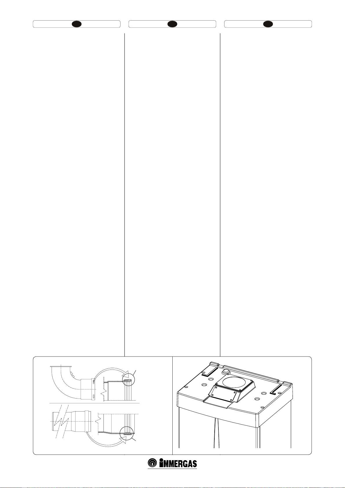
HU IERO
Tömítések (fekete színű) pozícionálása a “zöld
szériájú” füstcsőre. Üg yeljen arra, hogy a megfelelő
tömítéseket a helyezze be (könyökök és hosszabítók)
(1-10 ábra):
- tömítés sarkakkal, a könyököknél használatos;
- tömítés sarkak nélkü, a hosszabítóknál használatos.
MEGJ.: az alkatrészek olajozásakor (már a gyártó
elvégezte) lehet, hogy nem elegendő a megmaradt
kenőanyagot egy száraz ronggyal eltávolítani,
ilymódon a kapcsoló működését megkönnyítendő
szórja be a részeket a készlethez tartozó porral.
1.8 BESZERELÉS RÉSZLEGESEN VÉDETT
KÜLSŐ TÉRBE.
Megj.: részlegesen védett külső tér alatt olyan hely
értendő, ahol a kazánt nem érik közvetlenül az
időjárás viszontagságai (eső, hó, jégeső stb.).
t #UÓQVTÞOZÓMU LBNSÈT ÏT LÏOZT[FS IV[BUPT
kazán kiépítése.
A megfelelő borító készlet alkalmazásával lehetővé
válik a közvetlen levegő beszívása (1-11 ábr.) és a
füstgáz kiengedése egy kéménybe vagy közvetlenül
a szabadba.
Ebben a változatban a kazánt részlegesen védett
helyre be lehet beszerelni. Az ilymódon szerelt
kazán a B
Ennél a változatnál:
- az égéshez felhasznált levegőt a készülék
- az égéstermék elvezető csövét egyedi kéménybe
-es osztályba tartozik.
22
közvetlenül abból a helyiségből szívja el, ahol
felszerelésre kerül, ilyen esetben csakis állandóan szellőztetett helyiségben lehet felszerelni
és működtetni;
vagy közvetlenül a szabadba kell elvezetni.
A hatályos műszaki jogszabályokat be kell tartani.
t 'FEʩLÏT[MFUÚTT[FT[FSFMÏTFÈCSBSzerelje
le a középső furathoz képest oldalsó furatokról a
két védősapkát és a tömítéseket. Szerelje fel a Ø
80 elvezető karimát a kazán középső furatára a
tömítés felhelyezése után, majd húzza meg a készletben található csavarokkal. Szerelje fel a felső
borítót, és rögzítse az előzetesen a védősapkákból
kiszerelt csavarokkal. A 90°-os könyökidom Ø
80 megfelelő (sima) részét helyezze a karima Ø
80 tokrészébe (tömítőgyűrű közbeiktatásával)
egészen ütközésig, vágja le a tömítést az erre a
célra szolgáló horonyban a kívánt átmérőre (Ø
80), csúsztassa végig a könyök mentén, majd
rögzítse a lemezzel. Helyezze az elvezető cső
megfelelő(sima) oldalát a 90°-os könyökidom
Ø 80 tokrészébe , előtte ellenőrizze, hogy már
behelyezte-e a rozettát. Ily módon biztosítjuk
az elemek megfelelő illeszkedését és a rendszer
gáztömörségét.
Poziţionarea garniturilor (de culoare neagră)
pentru conductele de gaze arse ”serie verde”. Fiţi
atenţi la interpunerea corectă a garniturii (pentru
curbe sau prelungitoare) (Fig. 1-10):
- garnitură (A) cu gradaţii, de utilizat pentru
curbe;
- garnitură (B) fără gradaţii, de utilizat pentru
prelungitoare.
N.B.: în cazul în care lubrierea componentelor
(deja efectuată de constructor) nu este sucientă,
îndepărtaţi cu o cârpă uscată restul de lubriant şi
pentru a facilita cuplarea pulverizaţi componentele
cu talcul furnizat în kit.
1.8 INSTALARE ÎN EXTERIOR ÎN LOC
PARŢIAL PROTEJAT.
N.B.: prin loc parţial protejat se înţelege acela în
care aparatul nu e ex pus direct acţiunii intemperiilor
(ploaie, zăpadă, grindină, etc.).
t $POĕHVSBʴJFUJQ#DVDBNFSʅEFTDIJTʅʰJUJSBK
forţat.
Folosind kitul corespunzător de acoperire se poate efectua aspirarea aerului direct (Fig. 1-11) şi
evacuarea gazelor arse în coş individual sau direct
în exterior.
În această configurare este posibilă instalarea
centralei în loc parţial protejat. Centrala în această
congurare este clasicata tip B23.
Cu această congurare:
- admisia aerului se face direct din mediul în care
este instalat aparatul, care trebuie să e instalat
şi să funcţioneze numai în locuri permanent
ventilate;
- evacuarea gazelor arse trebuie să e legată la
un coş propriu sau să e canalizată direct în
atmosfera externă.
Trebuie aşadar să e respectate normele tehnice
în vigoare.
t .POUBSFLJUBDPQFSJSF'JHDemontaţi
din oriciile laterale faţă de cel central cele două
dopuri şi garniturile prezente. Instalaţi anşa Ø
80 de evacuare pe oriciul mai intern al centralei
interpunând garnitura prezenţa în kit şi închideţi
cu şuruburile din dotare. Instalaţi acoperişul
superior xând-o cu cele 4 şuruburi prezente în
kit interpunând garniturile respective. Cuplaţi
curba 90° Ø 80 cu latura moş (netedă), în latura
babă (cu garnituri tip buză) a anşei Ø 80 până la
aducerea în tamponare, xaţi garnitura făcând-o
să se deplaseze de-a lungul curbei, xaţi-o prin
intermediul plăcii de tablă şi strângeţi cu inelul
prezent în kit cu atenţie la xarea celor 4 pene
ale garniturii. Cuplaţi tubul de evacuare cu
latura moş (netedă), în latura babă a curbei 90°
Ø 80 asigurându-vă că aţi introdus deja rozeta
respectivă, în acest fel se va obţine etanşeitatea
articulaţiei elementelor ce compun kitul.
Positioning of the gaskets (black) for “green
range” ue extraction systems. Position the gasket
correctly (for bends and extensions) (Fig. 1-10):
- gasket (A) with notches, to use for bends;
- gasket (B) without notches, to use for extensions.
N.B.: if component lubrication (already carried
out by the manufacturer) is not sucient, remove
the residual lubricant using a dry cloth, then to
ease tting spread the elements with common or
industrial talc.
1.8 INSTALLATION OUTSIDE IN A PAR
TIALLY PROTECTED PLACE.
N.B.: a partially protected location is one in which
the appliance is not exposed to the direct action of
the weather (rain, snow, hail, etc..).
t $POGJHVSBUJPOUZQF # PQFO DIBNCFS BOE
forced draught.
Using the relevant cover kit direct air intake is
possible (Fig. 1-11) and fumes are exhausted into
a single ue or directly to the outside.
In this conguration it is possible to install the
boiler in a partially protected place. e boiler in
this conguration is classied as type B
With this conguration:
- air intake takes place directly from the environment in which the boiler is installed and only
functions in permanently ventilated rooms;
- the ue exhaust must be connected to its own
individual ue or channelled directly into the
external atmosphere.
The technical regulations in force must be respected.
t ,JUBTTFNCMZ'JHRemove the two plugs
and the seals present from the two holes to the
laterally to the central one. Install the Ø 80 outlet
ange on the central hole of the boiler, taking
care to insert the gasket supplied with the kit
and tighten by means of the screws provided.
Install the upper cover, fixing it using the 4
screws present in the kit, positioning the relevant
seals. Engage the 90° Ø 80 bend with the male
end (smooth) in the female end (with lip seal) of
the Ø 80 ange unit until it stops. Introduce the
gasket, making it run along the bend. Fix it using
the sheet steel plate and tighten by means of the
straps present in the kit, making sure to block
the 4 gasket aps. Fit the male end (smooth) of
the exhaust terminal up to the stop on the female
end of the bend 90° Ø 80, making sure that the
relevant ring is already tted; this will ensure
hold and joining of the elements making up the
kit.
.
23
(A)
(B)
1-10
1-11
19
Page 14
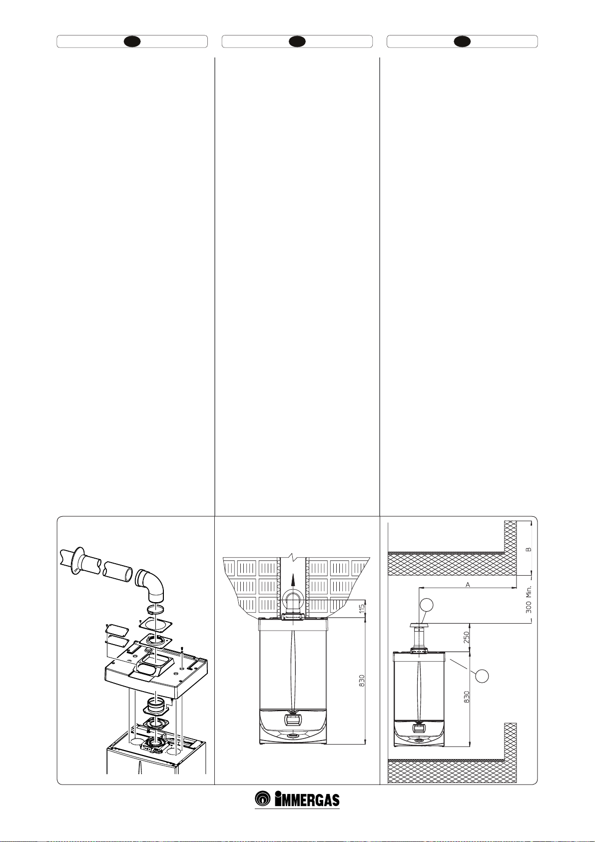
HU IERO
A fedőkészlet tartalmaz (1-12 ábra):
N° 1 db Hőformázott fedő
N°1 db Tömítést rögzítő lemez
N°1 db Tömítés
N°1 db Tömítésszorító szalag
N°1 db Égéslevegőt befedő lemez
Cső készlet tartalmaz:
N° 1 db Tömítés
N° 1 db Elvezető karima Ø 80
N° 1 db Elvezető cső Ø 80
N° 1 Elvezető cső Ø 80
N° 1 db Takarórózsa
Füstgázcső maximális hossza. Az füstelvezető
csövet (mind függőleges mind vízszintes irányban)
meg lehet hosszabbítani max. 30 m teljes egyenes
hosszig szigetelt csövekkel, a kondenz lecsapódásá-
nak elkerülése végett, amely a füstelvezető lehűlése
miatt következik ve.
t Bővítő idomok oldható csatlakozása. Esetleges
hosszabbítóknak a kéményrendszer egyéb
elemeihez történő oldható felszerelésékor a
következőképpen kell eljárni: csatlakoztassuk a
cső vagy könyök megfelelő (sima) végét a már
felszerelt utolsó elem tokrészébe (tömítőgyűrű
közbeiktatásával) ütközésig. Ily módon biztosítjuk az elemek megfelelő illeszkedését és a
rendszer gáztömörségét.
Tel epítés közvetlen függőleges csővel részlegesen
védett helyre - példa. Amennyiben az égéster-
mékek közvetlen elvezetéséhez a függőleges csövet
használja, az Ön felett levő erkélytől legalább 300
mm-es távolságot kell tartani Az A + B kvótának (az
Ön felett levő erkélyhez képest) nagyobbnak vagy
egyenlőnek kell lennie mint 2000 mm.
t ,JÏQÓUÏTGFEʩLÏT[MFUOÏMLàMSÏT[MFHFTFOWÏEFUU
helyen (C típusú kazán).
Amennyiben nem szereli le az oldalsó védősapkákat,
a fedő készlet nélkül szerelheti fel a készüléket a szabadban. A telepítés a koncentrikus függőleges szívás
/ elvezetés Ø60/100 készlettel történik, amelyre
vonatkozóan lásd a belső beszerelésre vonatkozó
bekezdést. Ebben a változatban a felső fedőkészlet,
amely garantálja a kazán kiegészítő védelmét, ajánlott, de nem kötelező.
Jelmagyarázat (1-14 ábra):
1 - Vízszintes végelemkészlet közvetlen elvezetéssel
2 - Égéslevegő fedőkészlet
Kitul acoperiş cuprinde (Fig. 1-12):
N° 1 Acoperiş termoformat
N°1 Placă blocare garnitură
N°1 Garnitură
N°1 Inel de strângere garnitură
N°1 Placă acoperire oriciu aspirare
Kitul terminal conţine:
N° 1 Garnitură
N° 1 Flanşă Ø 80 de evacuare
N° 1 Curba 90° Ø 80
N° 1 Tub evacuare Ø 80
N° 1 Rozetă
Întinderea maximă a ţevii de evacuare.Ţeava de
evacuare (atât pe verticală cât şi pe orizontală)
pentru a evita probleme de condensare a gazelor
arse datorate răcirii acestora prin perete poate
prelungită până la o măsură maximă de 30 m
rectilinii.
t Articularea prin cuplare a tuburilor prelun-
gitoare. Pentru a instala eventuale prelungiri
prin cuplare cu alte elemente ale sistemului
de evacuare a gazelor arse, trebuie să acţionaţi
cum urmează: Cuplaţi tubul sau cotul cu latura
moş (netedă) în latura babă (cu garnituri tip
buză) ale elementului precedent instalat până
la aducerea în tamponare, în acest mod se va
obţine etanşeitatea şi articularea elementelor în
mod corect.
Exemplu de instalare cu terminal vertical direct
în loc parţial protejat. Utilizând terminalul vertical
pentru evacuarea directă a produselor de ardere este
necesar să e respectată distanţa minimă de 300
mm faţă de balconul de deasupra (g. 1-14). Cota
A + B (tot faţă de balconul de deasupra), trebuie să
e egală sau mai mare de 2000 mm.
t $POĕHVSBSFBGʅSʅLJUBDPQFSJSFÔOMPDQBSʴJBM
protejat (centrală tip C).
Lăsând dopurile laterale montate, este posibilă instalarea aparatului la exterior fără kitul de acoperire
Instalarea se face, utilizând kiturile de admisie/
evacuare concentrice Ø60/100 pentru care se face
trimitere la paragraful respectiv la instalarea pentru
interior. În această congurare kitul de acoperire
superior care garantează o protecţie suplimentară
centralei este recomandabil dar nu obligatoriu.
Legenda (Fig. 1-14):
1 - Kit terminal vertical pentru evacuare
directă
2 - Kit acoperire aspirare
e cover kit includes (Fig. 1-12):
N° 1 ermoformed cover
N°1 Seal clamping plate
N°1 Gasket
N°1 Gasket tightening strap
N°1 Intake hole covering plate
e terminal kit includes:
N° 1 Gasket
N° 1 Ø 80 discharge ange
N° 1 Bend 90° Ø 80
N° 1 Ø 80 Drain pipe
N° 1 Ring
Max. length of exhaust ue. e exhaust duct
(in vertical or in horizontal) in order to prevent
problems of fume condensation owing to their
cooling through the wall can be extended to a max.
measurement of 30 straight metres.
t Coupling of extension pipes. To install snap-t
extensions with other elements of the fume extraction elements assembly, proceed as follows:
Install the pipe or elbow with the male side
(smooth) on the female section (with lip seal) to
the end stop on the previously installed element.
to ensure sealing eciency of the coupling.
Example of installation with direct vertical
terminal in partially protected location. When
the vertical terminal for direct discharge of combustion fumes is used, a minimum gap of 300 mm
must be le between the terminal and the balcony
above (Fig. 1-14). e distance A + B (always with
respect to the balcony above), must be equal to or
less than 2000 mm.
t $POĕHVSBUJPOXJUIPVUDPWFSLJUJOBQBSUJBMMZ
protected location (type C boiler).
By leaving the side plugs tted it is possible to
install the appliance externally without the cover
kit. Installation takes place using the Ø60/100 concentric intake/ exhaust kits. Refer to the paragraph
relative to indoor installation. In this conguration
the upper cover kit guarantees an additional protection for the boiler. It is recommended but not
compulsory.
Key (Fig. 1-14):
1 - Vertical terminal kit for direct discharge
2 - Intake cover kit
1-131-12
1-14
1
2
21
Page 15
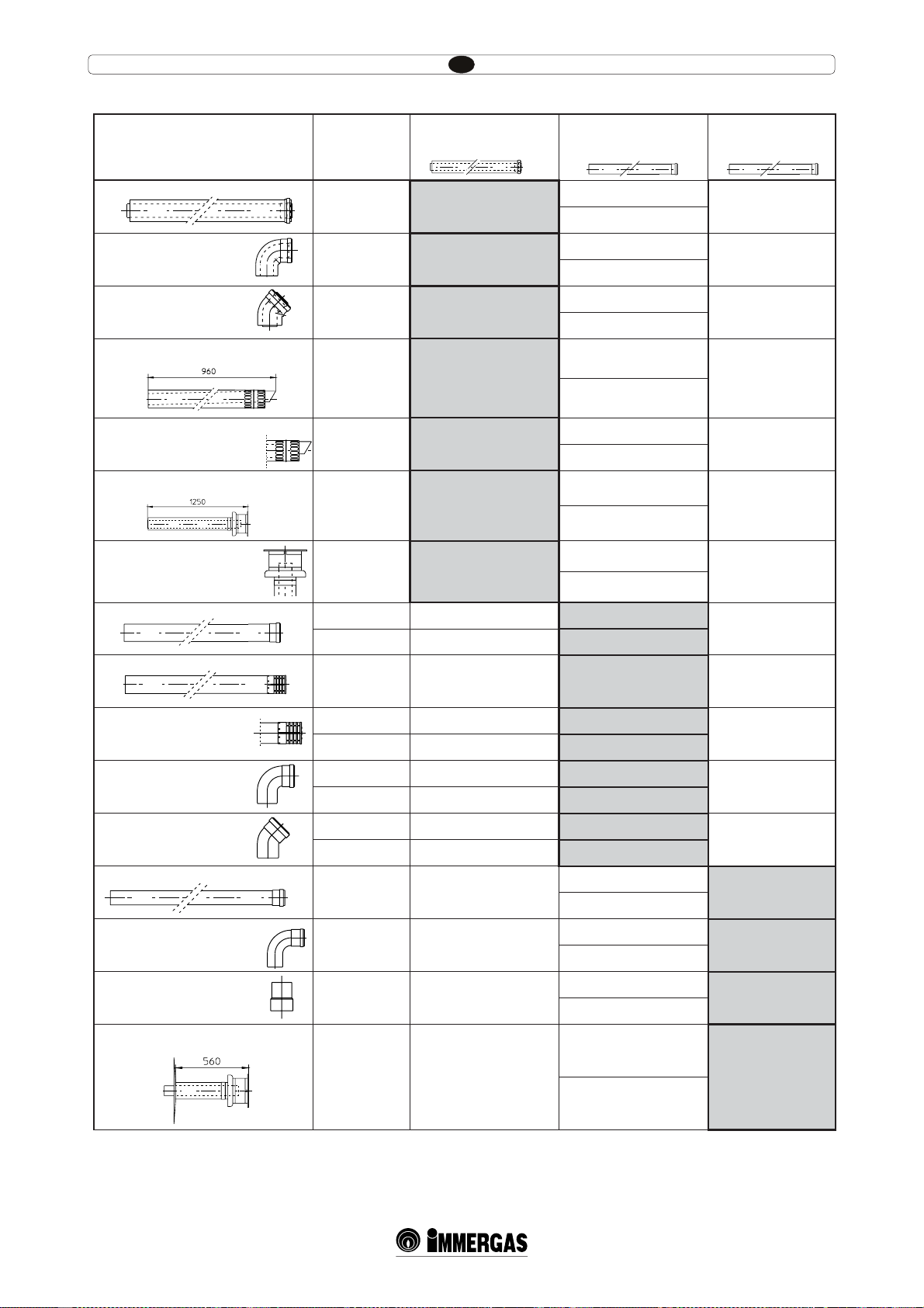
Ellenállási tényezők és megfelelő hosszúságok táblázatai.
HU
CSŐELEM TÍPUSA
Ø 60/100 1m-es koncentrikus cső
90° Ø 60/100 koncentrikus cső
45° Ø 60/100 koncentrikus cső
Ø 60/100-as égéslevegő-füstgáz komplett
végelem
Ø 60/100-as égéslevegő-füstgáz koncentrikus végelem
Ø 60/100-as égéslevegő-füstgáz komplett
végelem
Ø 60/100-as égéslevegő-füstgáz koncentrikus végelem
Tubo Ø 80 m 1
Ø 80 m 1-es komplett égéslevegő végelem
Áramlási ellenállá-
si tényező
(R)
Égéslevegő és
füstgáz 6,4
Égéslevegő és
füstgáz 8,2
Égéslevegő és
füstgáz 6,4
Ø60/100mm-es koncentrikus
cső egyenértékű
hosszúsága m-ben
m 1
m 1,3
m 1
Ø80 mm-es cső
egyenértékű hosszúsága
m-ben
Égéslevegő m 7,3
Füstgáz m 5,3
Égéslevegő m 9,4
Füstgáz m 6,8
Égéslevegő m 7,3
Füstgáz m 5,3
Ø 60 mm-es cső
egyenértékű hosszúsága
m-ben
Füstgáz m1,9
Füstgáz m 2,5
Füstgáz m 1,9
Égéslevegő m 17,2
Égéslevegő és
füstgáz 15
m 2,3
Füstgáz m 4,5
Füstgáz m 12,5
Égéslevegő és
füstgáz 10
Égéslevegő és
füstgáz 16,3
Égéslevegő és
füstgáz 9
m 1,5
m 2,5
m 1,4
Égéslevegő m 11,5
Füstgáz m 3,0
Füstgáz m 8,3
Égéslevegő m 18,7
Füstgáz m 4,9
Füstgáz m 13,6
Égéslevegő m 10,3
Füstgáz m 2,7
Füstgáz m 7,5
Égéslevegő 0,87 m 0,1 Égéslevegő m 1,0
Füstgáz m 0,4
Füstgáz 1,2 m 0,2 Füstgáz m 1,0
Égéslevegő 3 m 0,5 Égéslevegő m 3,4 Füstgáz m 0,9
Ø 80-as égéslevegő végelem
Ø 80-as füstgáz végelem
90° Ø 80-as könyök
45° Ø 80-as könyök
Ø 60 m 1-as cső a becsövezéshez
90° Ø 60-as könyök a becsövezéshez
Ø 80/60-as csökkentő
Ø 60-as vízszintes füstgáz komplett végelem
a becsövezéshez
Égéslevegő 2,2 m 0,35 Égéslevegő m 2,5
Füstgáz 1,9 m 0,3 Füstgáz m 1,6
Égéslevegő 1,9 m 0,3 Égéslevegő m 2,2
Füstgáz 2,6 m 0,4 Füstgáz m 2,1
Égéslevegő 1,2 m 0,2 Égéslevegő m 1,4
Füstgáz 1,6 m 0,25 Füstgáz m 1,3
Égéslevegő 3,8
Füstgáz 3,3 m 0,5
Füstgáz 2,7
Égéslevegő 4,0
Füstgáz 3,5 m 0,55
Füstgáz 2,9
Égéslevegő és
füstgáz 2,6
m 0,4
Égéslevegő m 3,0
Füstgáz m 2,1
Égéslevegő m 14
Füstgáz 12,2 m 1,9
Füstgáz m 10,1
Füstgáz m 0,6
Füstgáz m 0,8
Füstgáz m 0,5
Füstgáz m 1,0
Füstgáz m 1,1
Füstgáz m 0,8
Füstgáz m 3,7
25
Page 16
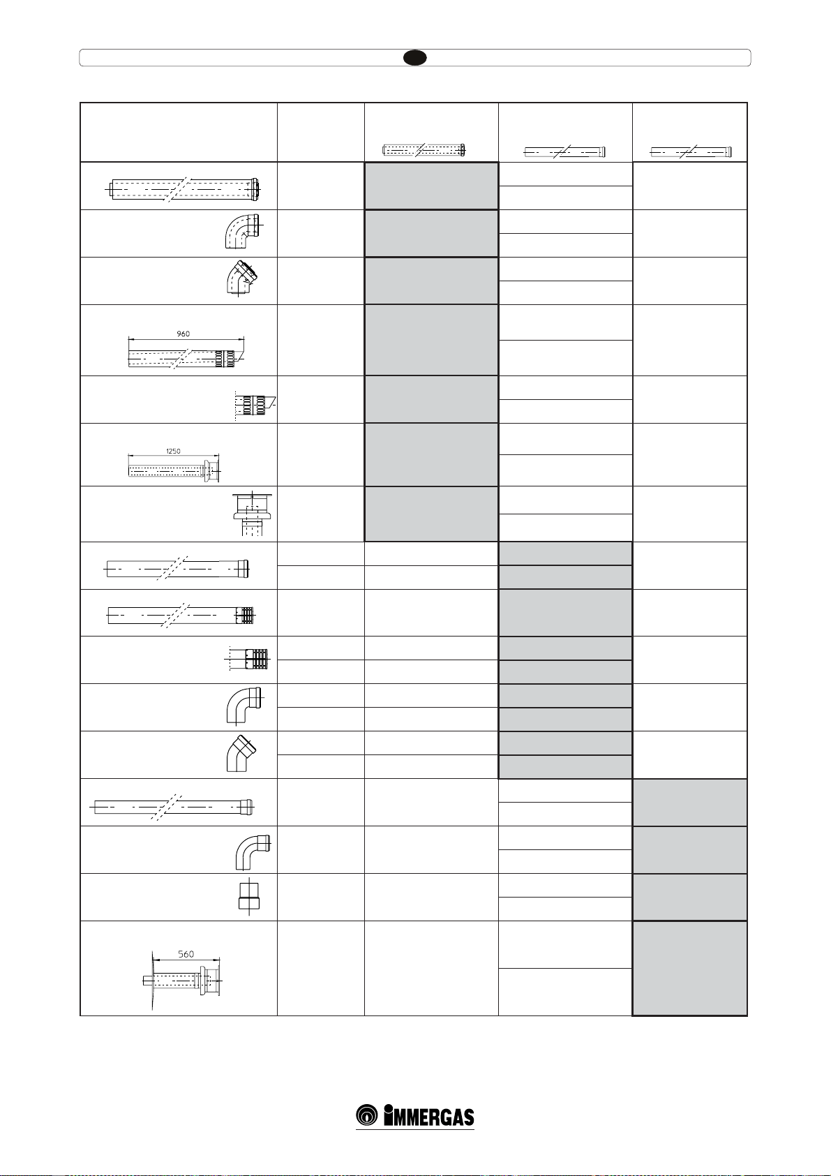
Tabelele factorilor de rezistenţă şi lungimi echivalente.
RO
TIP DE CONDUCTĂ
Tub concentric Ø 60/100 1 m
Curbă 90° concentrică Ø 60/100
Curbă 45° concentrică Ø 60/100
Terminal complet de aspirare-evacuare
concentrică orizontală Ø 60/100
Terminal de aspirare-evacuare
concentric orizontal Ø 60/100
Terminal complet de aspirare-evacuare
concentric vertical Ø 60/100
Terminal de aspirare-evacuare
concentric vertical Ø 60/100
Tub Ø 80 1 m
Terminal complet aspirare Ø 80 1 m
Factor de
Rezistenţă
(R)
Aspirare şi
Evacuare 6,4
Aspirare şi
Evacuare 8,2
Aspirare şi
Evacuare 6,4
Lungime
echivalentă in m tub concen-
tric Ø 60/100
m 1
m 1,3
m 1
Lungime
echivalentă
în m tub Ø 80
Aspirare m 7,3
Evacuare m 5,3
Aspirare m 9,4
Evacuare m 6,8
Aspirare m 7,3
Evacuare m 5,3
Lungime
echivalentă
in m tub Ø 60
Evacuare m1,9
Evacuare m 2,5
Evacuare m 1,9
Aspirare m 17,2
Aspirare şi
Evacuare 15
m 2,3
Evacuare m 4,5
Evacuare m 12,5
Aspirare şi
Evacuare 10
Aspirare şi
Evacuare 16,3
Aspirare şi
Evacuare 9
m 1,5
m 2,5
m 1,4
Aspirare m 11,5
Evacuare m 3,0
Evacuare m 8,3
Aspirare m 18,7
Evacuare m 4,9
Evacuare m 13,6
Aspirare m 10,3
Evacuare m 2,7
Evacuare m 7,5
Aspirare 0,87 m 0,1 Aspirare m 1,0
Evacuare m 0,4
Evacuare 1,2 m 0,2 Evacuare m 1,0
Aspirare 3 m 0,5 Aspirare m 3,4 Evacuare m 0,9
Terminal de aspirare Ø 80
Terminal de evacuare Ø 80
Curbă 90° Ø 80
Curbă 45° Ø 80
Tub Ø 60 1 m pentru intubare
Curbă 90° Ø 60 pentru intubare
Reducere Ø 80/60
Terminal complet de evacuare
vertical Ø 60 pentru intubare
Aspirare 2,2 m 0,35 Aspirare m 2,5
Evacuare 1,9 m 0,3 Evacuare m 1,6
Aspirare 1,9 m 0,3 Aspirare m 2,2
Evacuare 2,6 m 0,4 Evacuare m 2,1
Aspirare 1,2 m 0,2 Aspirare m 1,4
Evacuare 1,6 m 0,25 Evacuare m 1,3
Aspirare 3,8
Evacuare 3,3 m 0,5
Evacuare 2,7
Aspirare 4,0
Evacuare 3,5 m 0,55
Evacuare 2,9
Aspirare şi
Evacuare 2,6
m 0,4
Aspirare m 3,0
Evacuare m 2,1
Aspirare m 14
Evacuare 12,2 m 1,9
Evacuare m 10,1
Evacuare m 0,6
Evacuare m 0,8
Evacuare m 0,5
Evacuare m 1,0
Evacuare m 1,1
Evacuare m 0,8
Evacuare m 3,7
26
Page 17
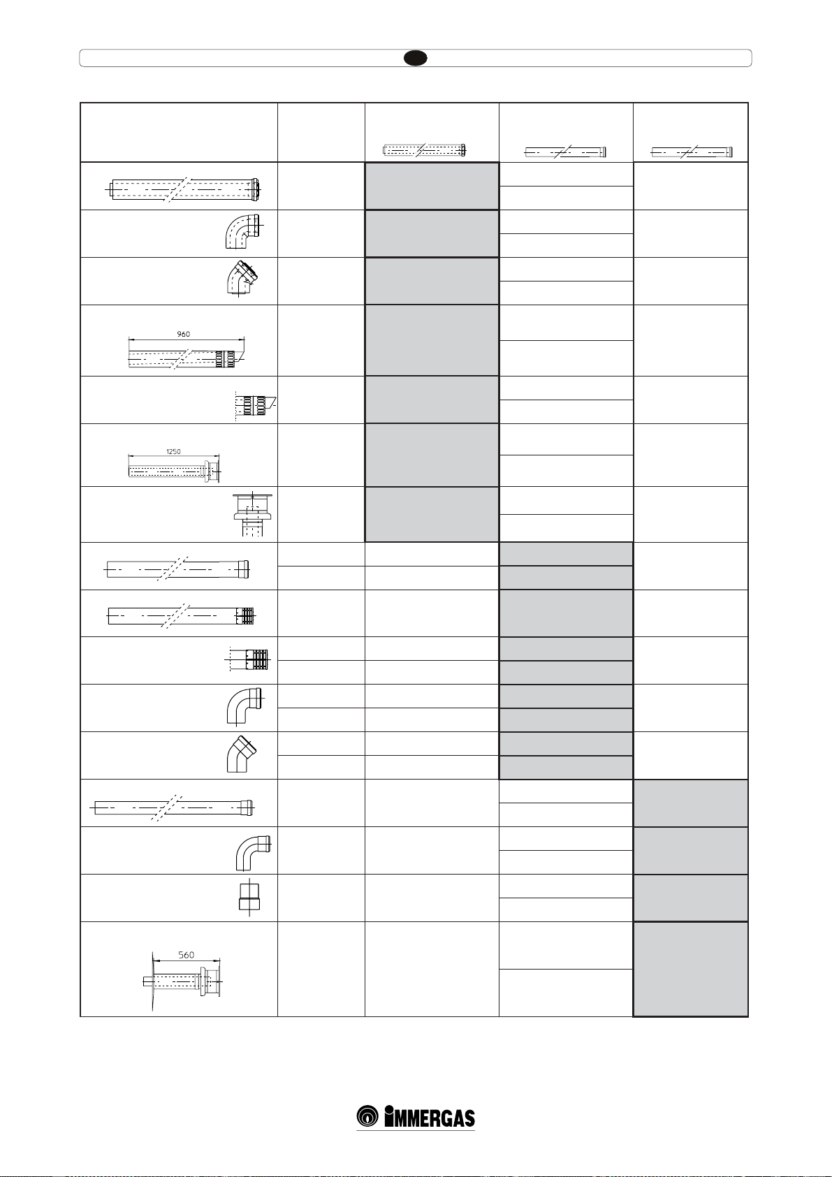
Resistance Factors and Equivalent Lengths Table.
IE
DUCT TYPE
Concentric pipe Ø 60/100 m 1
Bend 90° concentric Ø 60/100
Bend 45° concentric Ø 60/100
Terminal complete with intake-exhaust
horizontal concentric Ø 60/100
Intake-exhaust terminal horizontal concentric Ø 60/100
Terminal complete with intake-exhaust
vertical concentric Ø 60/100
Intake-exhaust terminal vertical
concentric Ø 60/100
Tubo Ø 80 m 1
Complete intake terminal Ø 80, 1 m
Resistance Factor
(R)
Intake and
Exhaust 6,4
Intake and
Exhaust 8,2
Intake and
Exhaust 6,4
Length in m of concentric pipe
Ø 60/100
m 1
m 1,3
m 1
Equivalent length in metres
of pipe Ø 80
Intake m 7,3
Exhaust m 5,3
Intake m 9,4
Exhaust m 6,8
Intake m 7,3
Exhaust m 5,3
Equivalent length in
metres of pipe Ø 60
Exhaust m1,9
Exhaust m 2,5
Exhaust m 1,9
Intake m 17,2
Intake and
Exhaust 15
m 2,3
Exhaust m 4,5
Exhaust m 12,5
Intake and
Exhaust 10
Intake and
Exhaust 16,3
Intake and
Exhaust 9
m 1,5
m 2,5
m 1,4
Intake m 11,5
Exhaust m 3,0
Exhaust m 8,3
Intake m 18,7
Exhaust m 4,9
Exhaust m 13,6
Intake m 10,3
Exhaust m 2,7
Exhaust m 7,5
Intake 0,87 m 0,1 Intake m 1,0
Exhaust m 0,4
Exhaust 1,2 m 0,2 Exhaust m 1,0
Intake 3 m 0,5 Intake m 3,4 Exhaust m 0,9
Intake terminal Ø 80
Exhaust terminal Ø 80
Bend 90° Ø 80
Bend 45° Ø 80
Pipe Ø 60 m 1 for ducting
Bend 90° Ø 60 for ducting
Reduction Ø 80/60
Terminal complete with vertical exhaust Ø
60 for ducting
Intake 2,2 m 0,35 Intake m 2,5
Exhaust 1,9 m 0,3 Exhaust m 1,6
Intake 1,9 m 0,3 Intake m 2,2
Exhaust 2,6 m 0,4 Exhaust m 2,1
Intake 1,2 m 0,2 Intake m 1,4
Exhaust 1,6 m 0,25 Exhaust m 1,3
Intake 3,8
Exhaust 3,3 m 0,5
Exhaust 2,7
Intake 4,0
Exhaust 3,5 m 0,55
Exhaust 2,9
Intake and
Exhaust 2,6
m 0,4
Intake m 3,0
Exhaust m 2,1
Intake m 14
Exhaust 12,2 m 1,9
Exhaust m 10,1
Exhaust m 0,6
Exhaust m 0,8
Exhaust m 0,5
Exhaust m 1,0
Exhaust m 1,1
Exhaust m 0,8
Exhaust m 3,7
27
Page 18
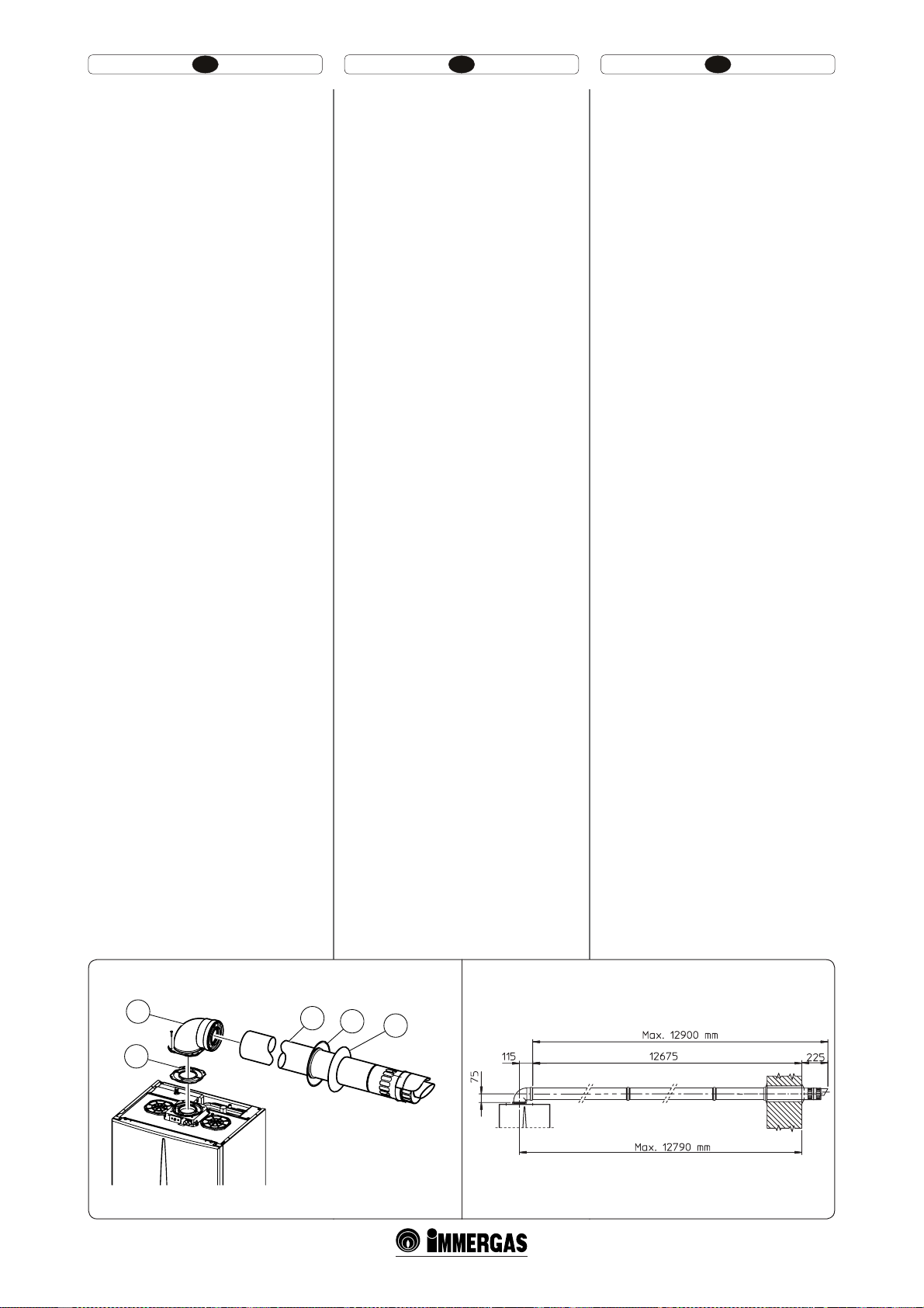
HU IERO
1.9 BELTÉRI BESZERELÉS.
t $UÓQVTÞIFSNFUJLVTBO[ÈSULBNSÈTÏTLÏOZT[FS
huzatos kazán kiépítése.
Vízszintes Ø60/100mm-es égéslevegő –füstgáz
rendszer szerelési készlet. Felszerelés (1-5. ábra):
Csatlakoztassuk a peremes könyököt (2) a tömítés
(1) (amely nem igényel olajozást) közbeiktatásával
a kazán hossztengelyéhez közelebbi csatlakozó
csonkra és rögzítsük a mellékelt csavarokkal.
Csatlakoztassuk a Ø60/100mm–es végelem (3)
megfelelő (sima) végét a könyök (2) tokrészébe
ütközésig. Előzőleg ne felejtsük el felhelyezni a
külső és belső takarórózsát. Ily módon biztosítjuk
az elemek megfelelő illeszkedését és a rendszer
gáztömörségét.
Megj.: amennyiben a kazánt olyan helyre telepítjük, ahol a hőmérséklet nagyon alacsony lehet,
a normál fagyásálló készlet helyett a különlegeset
szerelje fel.
t NNFT LPODFOUSJLVTUPMEØDTʩFMFNFL
és könyökök csatlakoztatása. Esetleges toldó
elemeknek a kéményrendszerhez való csatlakoztatása esetén a következőképpen kell eljárni:
csatlakoztassuk a koncentrikus cső vagy könyök
megfelelő (sima) végét a már felszerelt utolsó
elem tokrészébe (tömítőgyűrű közbeiktatásával)
ütközésig. Ilymódon biztosítjuk az elemek
megfelelő illeszkedését és a rendszer gáztömörségét.
Az Ø60/100mm-es szerelési készlet felszerelhető
hátsó, jobb oldali, bal oldali és elülső kivezetéssel.
t 5PMEØFMFNFLGàHHʩMFHFTLÏT[MFUIF[ÈCSB
A Ø 60/100 mm-es égéslevegő / füstgáz vízszintes
készletet maximum 12,9 -rel lehet függőlegesen
megtoldani, beleértve a rácsos végelemet, de nem
a kazánból kivezető koncentrikus könyökidomot. Ez a kiépítés megfelel egy 100-as áramlási
ellenállás tényezőnek. Az ilyen esetekben az erre
a célra szolgáló toldalékidomokat igényelni
kell.
MEGJ.: A csőelemeket a szerelés során 3 méterenként tiplis csőbilinccsel rögzíteni kell.
t ,àMTʩSÈDTPTWÏHFMFNMegj.: biztonsági okokból
még ideiglenesen sem szabad soha eltakarni a
kazán égéslevegő / füstgáz kimenetét.
A készlet tartalma (1-15. ábra):
N° 1 - tömítőgyűrű (1)
N° 1 - koncentrikus Ø 60/100-as könyök (2)
N° 1 - koncentrikus égésl./füstg. Ø 60/100-as
könyök (3)
N° 1 - Belső takarórózsa (4)
N° 1 - külső takarórózsa (5)
1.9 INSTALARE ÎN INTERIOR.
t $POĕHVSBSFB UJQ $ DVDBNFSʅ FUBOʰ ʰJUJSBK
forţat.
Kituri orizontale de aspirare-evacuare Ø 60/100.
Montaj kit (Fig. 1-15): instalaţi curba cu anşa (2)
pe oriciul central al centralei interpunând garnitura (1) (care nu necesită lubriere) poziţionând-o cu
proeminenţele circulare în jos în contact cu anşa
centralei şi închideţi cu şuruburile prezente în kit.
Cuplaţi tubul terminal concentric Ø 60/100 (3)
cu latura moş (netedă), în latura babă a curbei (2)
până o aduceţi în tamponare, asigurându-vă că aţi
introdus deja respectiva rozetă internă şi externă,
în acest mod se va obţine etanşeitatea şi articularea
elementelor ce compun kitul.
N.B.: pentru o funcţionare corectă a sistemului este
necesar ca terminalul cu grilaj să e instalat corect
asigurându-vă că, indicaţia ”înalt” de pe terminal
este respectată în timpul instalării.
t ·NCJOBSFBQSJODVQMBSFBUVCVSJMPSTBVQSFMVOHJ-
toarelor şi coatelor concentrice Ø60/100. Pentru
instalarea eventualelor prelungitoare prin cuplare cu alte elemente ale sistemului de evacuare
gazelor arse, trebuie să acţionaţi cum urmează:
cuplaţi tubul concentric sau cotul concentric cu
latura moş (netedă) în latura-babă (cu garnitură
tip buză) a elementului instalat anterior, până
ajunge în tamponare, în acest mod se va obţine
etanşeitatea şi îmbinarea corectă a elementelor.
Kitul Ø 60/100 poate instalat cu ieşirea posterioară,
laterală dreapta, laterală stânga şi anterioară.
t 1SFMVOHJUPBSFQFOUSV LJU PSJ[POUBM ĕH
Kitul orizontal de aspirare – evacuare Ø 60/100
poate prelungit până la o măsură maximă de
12,9 m orizontali, inclusiv terminalul tip grilaj şi
exclusă curba concentrică la ieşirea din centrală.
Această conguraţie corespunde unui factor de
rezistenţă egal cu 100. In aceste cazuri e necesar
să solicitaţi prelungitoarele adecvate.
N.B.: în timpul instalării conductelor e necesar să
instalaţi la ecare 3 metri un inel de întrerupere
traseu cu diblu.
t (SJMBKFYUFSON.B.: în scopuri de siguranţă se
recomandă să nu obturaţi, nici măcar provizoriu,
terminalul de aspirare/evacuare al centralei.
Kitul conţine (Fig. 1-15):
N° 1 - Garnitură (1)
N° 1 - Curbă concentrică Ø 60/100 (2)
N° 1 - Terminal concentric aspirare/evacuare Ø
60/100 (3)
N° 1 - Rozetă internă albă (4)
N° 1 - Rozetă externă gri (5)
1.9 INDOOR INSTALLATION.
t 5ZQF$ DPOĕHVSBUJPO TFBMFEDIBNCFS BOE
forced draught.
Horizontal intake kits - exhaust Ø 60/100. Kit
assembly (Fig. 1-15): install the bend with ange
(2) on the central hole of the boiler, positioning
the gasket (1) (which does not require lubrication)
positioning it with the circular projections downwards in contact with the boiler ange and tighten
using the screws preset in the kit. Fit the Ø 60/100
(3) concentric terminal pipe with the male end
(smooth) to the female end of the bend (2) up to the
stop; making sure that the internal ring and external
ring have been tted, this will ensure sealing and
joining of the elements making up the kit.
N.B.: for correct functioning of the system the terminal with grid must be installed correctly ensuring
that, the “high” indication present on the terminal
is respected on installation.
t $PVQMJOHFYUFOTJPOQJQFTBOEDPODFOUSJDFMCPXT
Ø 60/100. To snap-t extensions with other elements of the fume extraction elements, operate
as follows Install the concentric pipe or elbow
with the male side (smooth) on the female
section (with lip seal) to the end stop on the
previously installed element. to ensure sealing
eciency of the coupling.
e kit Ø 60/100 can be installed with the rear, rig ht
side, le side or front outlet.
t &YUFOTJPOTGPSIPSJ[POUBM LJU 'JH ćF
horizontal intake/exhaust kit Ø 60/100 can be
extended up to a max. horizontal distance of 12.9
m including the terminal with grid and excluding
the concentric bend leaving the boiler. is conguration corresponds to a resistance factor of
100. In these cases the special extensions must
be requested.
N.B.: When installing the ducts, a section clamp
with pin must be installed every 3 metres.
t &YUFSOBMHSJMMN.B.: for safety purposes, do not
even temporarily obstruct the boiler intake/
exhaust terminal.
e kit includes (Fig. 1-15):
N° 1 - Gasket (1)
N° 1 - Concentric bend Ø 60/100 (2)
N° 1 - Concentric terminal int./exhaust Ø
60/100 (3)
N° 1 - Internal white ring (4)
N° 1 - External grey ring (5)
C13
2
3
4
5
C13
1
1-15
1-16
29
Page 19
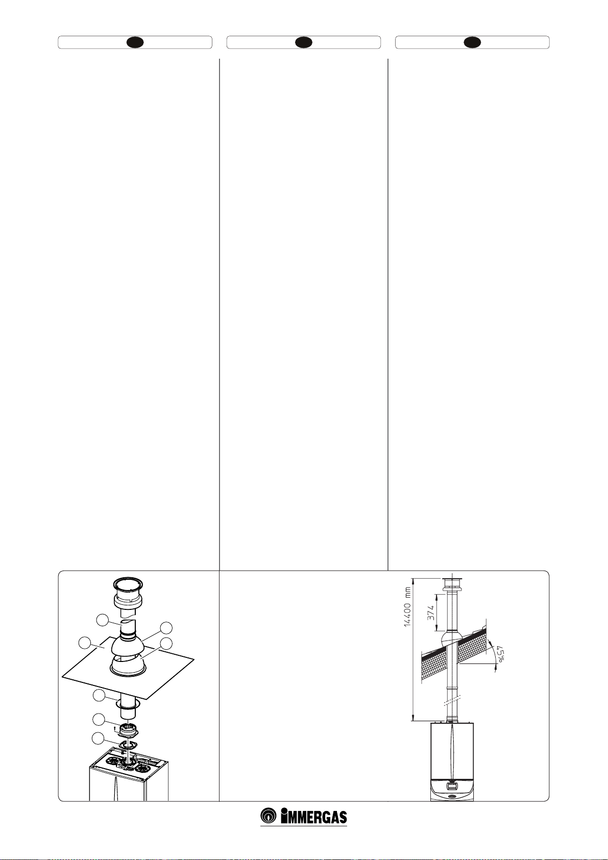
HU IERO
Függőleges Ø 60/100 mm–es szerelési készlet
alumínium tetőátvezetővel.
Felszerelés (1-17. ábra): Csatlakoztassuk a koncentrikus indító elemet (2) a tömítés (1)(amely
nem igényel olajozást) közbeiktatásával a kazán
hossztengelyéhez közelebbi csatlakozó csonkra, és
rögzítsük a mellékelt csavarokkal.
Az alumínium áltetőátvezető beszerelése: helyettesítse az alumíniumlemezes cserepekkel (4), olymódon alakítva, hogy az esővizet elvezesse. Helyezzük
az alumínium tetőátvezetőre a x félgömbhéjat
(6), és illesszük a helyére az égéslevegő-füstgáz
csövet (5). A koncentrikus Ø 60/100 -es csövet (5)
szűkebb (sima) végével csatlakoztassuk a bővítő
idom (2) tokrészébe ütközésig. Előzőleg ne feledjük el felhelyezni rá a takarórózsát (3). Ilymódon
biztosítjuk az elemek megfelelő illeszkedését és a
rendszer gáztömörségét.
t ,PODFOUSJLVTUPMEØDTʩFMFNFL ÏT LÚOZÚLÚL
csatlakoztatása. Esetleges toldó elemeknek a
kéményrendszerhez való csatlakoztatása esetén
a következőképpen kell eljárni: csatlakoztassuk a
koncentrikus cső vagy könyök megfelelő (sima)
végét a már felszerelt utolsó elem tokrészébe
(tömítőgyűrű közbeiktatásával) ütközésig.
Ilymódon biztosítjuk az elemek megfelelő illeszkedését és a rendszer gáztömörségét.
Figyelem: ha a koncentrikus füstcső végelemet és/
vagy a koncentrikus toldó elemet rövidíteni szükséges, gyelembe kell venni, hogy a belső csőnek 5
mm-nyire ki kell állnia a külső csőhöz képest.
Ez a különleges végelem lehetővé teszi a füst elvezetését és az égéshez szükséges levegő beszívását
függőleges irányban.
Megj.: a vízszintes Ø 60/100 mm-es allumínium
tetőátvezetős szerelési készlet felszerelhető laposés legfeljebb 45% (24°) dőlésszögű tetőre; minden
esetben ügyelni kell a végelem zárósapkája és a fél
gömbhéj közti előírt távolságra (374mm) (1-18
ábra).
A vízszintes szerelési készlet így összeállítva egyenes vonalban függőlegesen legfeljebb 14,4 mm-ig
hosszabbítható meg, ebbe a végelem is beleszámít.
Ennek az összeállításnak az áramlási ellenállási
tényezője 100-nak felel meg. A szükséges toldó
elemeket külön meg kell rendelni.
A készlet tartalma (1-17. ábra):
N° 1 - Tömítés (1)
N° 1 - Koncentrikus induló elem (2)
N° 1 - Takarórózsa (3)
N° 1 - Alumíniumcserép (4)
N° 1 - Ø 60/100-as égésl./füstg. koncentrikus cső (5)
N° 1 - Rögzített félgömbhély (6)
N° 1 - Mozgó félgömbhély (7)
Kit vertical cu ţiglă din aluminiu Ø 60/100. Montare kit (Fig. 1-17): instalaţi anşa concentrică (2) pe
oriciul central al centralei, interpunând garnitura
(1) (care nu necesită lubriere) poziţionând-o cu
proeminenţele circulare în jos în contact cu anşa
centralei şi închideţi cu şuruburile din kit.
Instalarea ţiglei false din aluminiu: înlocuiţi ţiglele
cu placa din aluminiu (4) modelând-o astfel încât
apa de ploaie să poată curge. Poziţionaţi pe ţigla
din aluminiu dispozitivul de protecţie x (6) şi
inseraţi tubul de aspirare-evacuare (5). Cuplaţi
terminalul concentric Ø 60/100 cu latura moş (5)
(netedă), în anşă (2) până la aducerea acestuia în
tamponare,asigurându-vă că aţi introdus în prealabil rozeta (3), în acest mod se va obţine etanşeitatea
şi asamblarea elementelor care fac parte din kit.
t ·NCJOBSFBQSJODVQMBSFBUVCVSJMPSTBVQSFMVO-
gitoarelor şi coturilor concentrice. Pentru instalarea eventualelor prelungitoare prin cuplare
cu alte elemente ale sistemului de evacuare a
gazelor arse, trebuie să acţionaţi după cum
urmează: Cuplaţi tubul concentric sau cotul
cu latura concentrică cu latura moş (netedă) în
latura-babă (cu garnitură tip buză) a elementului
instalat anterior, până ajunge în tamponare, în
acest mod se va obţine etanşeitatea şi îmbinarea
corectă a elementelor.
Atenţie: când este necesar scurtaţi terminalul de
evacuare şi/sau tubul prelungitor concentric, aveţi
în vedere că tubul intern trebuie să iasă în afară
mereu cu 5 mm faţă de tubul extern.
Acest terminal anume permite evacuarea gazelor
arse şi aspirarea aerului necesar la combustia în
sens vertical.
N.B.: kitul vertical Ø 60/100 cu ţigla din aluminiu
permite instalarea pe terase şi pe acoperişuri cu înclinare maximă de 45% (24°) şi înălţimea între acoperişul
terminal al coşului şi dispozitivul de protecţie (374
mm) se respectă întotdeauna (Fig. 1-18).
Kitul vertical cu această conguraţie poate prelungit până la maxim 14,4 m rectilinii verticali, inclusiv
terminalul. Această conguraţie corespunde unui
factor de rezistenţă egal cu 100. În acest caz este
necesar să solicitaţi prelungitoarele corespunzătoare
prin cuplare.
Kitul conţine (Fig. 1-17):
N° 1 - Garnitură (1)
N° 1 - Flanşă babă concentrică (2)
N° 1 - Rozetă (3)
N° 1 - Ţiglă din aluminiu (4)
N° 1 - Tub concentric aspirare/evacuare Ø 60/100 (5)
N° 1 - Dispozitiv de protecţie x (6)
N° 1 - Dispozitiv de protecţie mobil (7)
Vertical kit with aluminium tile Ø 60/100. Kit
assembly (Fig. 1-17): install the concentric ange
(2) on the central hole of the boiler, positioning the
gasket (1) (which does not require lubrication) positioning it with the circular projections downwards
in contact with the boiler ange and tighten using
the screws present in the kit.
Imitation aluminium tile installation: replace the
tile with the aluminium sheet (4), shaping it to
ensure that rainwater runs o. Position the xed
half-shell (6) and insert the intake/exhaust pipe
(5). Fit the Ø 60/100 (3) concentric terminal pipe
with the male end (5) (smooth) into the ange (2)
up to the stop; making sure that the ring has been
tted (3), this will ensure sealing and joining of the
elements making up the kit.
t $PVQMJOHFYUFOTJPOQJQFTBOEDPODFOUSJDFMCPXT
To install snap-t extensions with other elements
of the fume extraction elements assembly, proceed as follows: Install the concentric pipe or
elbow with the male side (smooth) on the female
section (with lip seal) to the end stop on the
previously installed element. to ensure sealing
eciency of the coupling.
Important: if the exhaust terminal and/or extension
concentric pipe needs shortening, consider that the
internal duct must always protrude by 5 mm with
respect to the external duct.
is specic terminal enables ue exhaust and
air intake, necessary for combustion, in a vertical
direction.
N.B.: e vertical kit Ø 60/100 with aluminium
tile enables installation on terraces and roofs
with maximum slope of 45% (24°) and the height
between the terminal cap and half-shell (374 mm)
must always be respected (Fig. 1-18).
The vertical kit with this configuration can be
extended to a max. straight vertical length of 14.4
m including the terminal. is conguration corresponds to a resistance factor of 100. In this case
the special extensions must be requested.
e kit includes (Fig. 1-17):
N° 1 - Gasket (1)
N° 1 - Female concentric ange (2)
N° 1 - Ring (3)
N° 1 - Aluminium tile (4)
N° 1 - Int./exhaust concentric pipe Ø 60/100 (5)
N° 1 - Fixed half-shell (6)
N° 1 - Mobile half-shell (7)
C33
C33
* MAXIMÁLIS HOSSZÚSÁG
5
4
3
2
1
7
6
1-17
* LUNGIME MAXIMĂ
* MAXIMUM LENGTH
*
1-18
31
Page 20
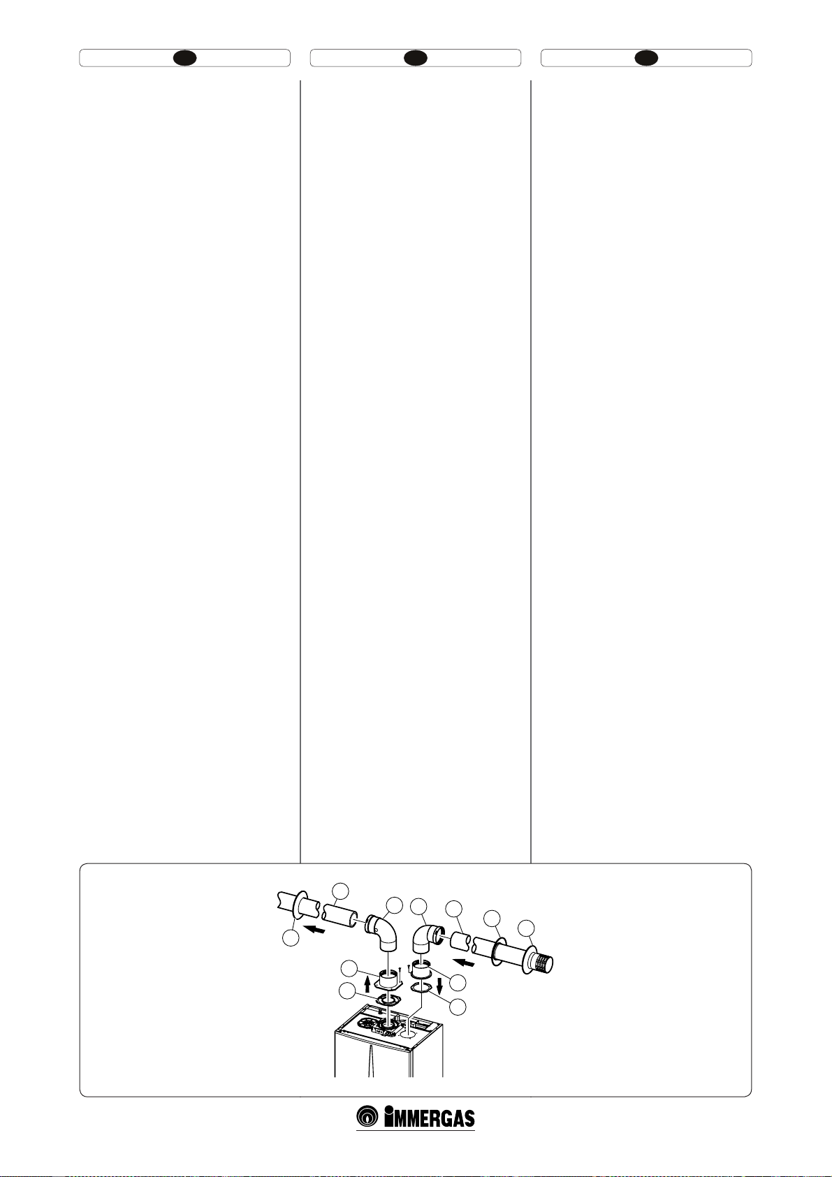
HU IERO
Ø80/80mm-es szétválasztó készlet. Az Ø80/80mmes elosztó készlet lehetővé teszi a füstgázelvezető és a
levegőbeszívó cső különválasztását az ábrán látható
rajz szerint. Az (A) csövön (csakis műanyagból,
hogy a savas lecsapódásoknak ellenálljon) távozik
az égéstermék. A (B) jelű csövön (ez is műanyagból)
kerül beszívásra az égéshez szükséges levegő. Az
égéslevegő csövet (B) a középső füstelvezető csőtől
(A) mind jobbra, mind balra lehet felszerelni.
Mindkét cső bármely irányban vezethető.
t "[NNFTT[ÏUWÈMBT[UØLÏT[MFUGFMT[FSF-
lése. Illesszük az indító elemet (4) a tömítés (1)
(amely nem igényel olajozást) közbeiktatásával
a kazán hossztengelyéhez közelebbi csatlakozó
csonkra, és rögzítsük a mellékelt a készleten
levő hatszögűfejű csavarokkal. Távolítsuk el a
hossztengelytől távolabbi csonkban található
lapos karimát, és illesszük a helyére a peremes
indító elemet (3) a kazánban található tömítés
(2) közbeiktatásával, majd rögzítsük a mellékelt
csavarmentes csavarokkal. Csatlakoztassuk a
könyököket (5) megfelelő (sima) végükkel az
indító elemek (3 és 4) tokrészébe. Illesszük a
helyére az égéslevegő végelemet (6) megfelelő
(sima) végével a könyök (5) tokrészébe ütközésig,
előzőleg ne feledjük el felhelyezni rá a külső és a
belső takarórózsát. Csatlakoztassuk a füstcső (9)
megfelelő (sima) végét a könyök (5) tokrészébe
ütközésig, előzőleg ne felejtsük el felhelyezni
a belső takarórózsát. Ily módon biztosítjuk az
elemek megfelelő illeszkedését és a rendszer
tömörségét.
A készlet tartalmaz (1-20 ábra):
N° 1 - Füstcső tömítés (1)
N° 1 - Indító elem tömítés (2)
N° 1 - Égéslevegő induló elem (3)
N° 1 - Füstcső induló elem (4)
N° 2 - Ø80mm-es 90°-os könyök (5)
N° 1 - Ø80mm-es égéslevegő-cső végelem Ø 80 (6)
N° 2 - Belső takarórózsa (7) fehér
N° 1 - Külső takarórózsa (8) szürke
N° 1 - Ø80mm-es füstcső (9)
t 5PMEØFMFNFLÏTLÚOZÚLJEPNPLDTBUMBLP[UBUÈTB
Esetleges toldó elemeknek a kéményrendszerhez
való csatlakoztatása esetén a következőképpen
kell eljárni: csatlakoztassuk a koncentrikus cső
vagy könyök megfelelő (sima) végét a már felszerelt utolsó elem tokrészébe (tömítőgyűrű közbeiktatásával) ütközésig. Ily módon biztosítjuk
az elemek megfelelő illeszkedését és a rendszer
gáztömörségét.
Kit separator Ø 80/80. Kitul separator Ø 80/80,
permite separarea ţevilor de evacuare a gazelor
arse şi de aspirare aer conform schemei de la gură.
Din ţeava (A) (riguros din material plastic pentru
a rezista la condensările acide) sunt expulzate
produsele combustiei. Din ţeava (B) (şi aceasta din
material plastic) este aspirat aerul necesar pentru
combustie. Ţeava de aspirare (B) poate instalată
indiferent la dreapta sau la stânga faţă de tubul
central de evacuare (A). Ambele ţevi pot orientate
în orice direcţie.
t .POUBK,JU 'JH JOTUBMBʴJĘBOʰBQF
oriciul central al centralei, interpunând garnitura (1) (ce nu necesită lubriere) poziţionând-o
cu proeminenţele circulare în jos în contact cu
anşa cazanului şi închideţi cu şuruburile cu
cap hexagonal şi ascuţit prezente în kit. Scoateţi
anşa plată prezentă în oriciul lateral faţă de
cel central (conform cerinţelor) şi înlocuiţi-o
cu anşa (3) interpunând garnitura (2) deja
prezentă pe centrală şi închideţi cu şuruburile
autoletante cu vârf din dotare. Cuplaţi curbele (5) cu latura moş (netedă) în latura babă a
anşelor (3 şi 4). Cuplaţi terminalul de aspirare
(6) cu latura moş (netedă), în latura babă a curbei
(5) până la aducerea în tamponare, asigurânduvă că aţi inserat rozetele corespunzătoare interne.
Cuplaţi ţeava de evacuare (9) cu latura moş
(netedă), în latura babă a curbei (5) până la aducerea în tamponare, asigurându-vă că aţi inserat
rozeta corespunzătoare internă, în acest mod se
va obţine etanşeitatea şi asamblarea elementelor
care fac parte din kit.
Kitul conţine (Fig. 1-20):
N° 1 - Garnitură evacuare (1)
N° 1 - Garnitură etanşă anşă (2)
N° 1 - Flanşă babă aspirare (3)
N° 1 - Flanşă babă evacuare (4)
N° 2 - curbă 90° Ø 80 (5)
N° 1 - Terminal aspirare Ø 80 (6)
N° 2 - Rozete interne albe (7)
N° 1 - Rozetă externă gri (8)
N° 1 - Tub evacuare Ø 80 (9)
t ·NCJOBSFBQSJODVQMBSFBUVCVSJMPSʰJDPUVSJMPS
Pentru instalarea eventualelor prelungitoare
prin cuplare cu alte elemente ale sistemului de
evacuare gaze arse, trebuie să operaţi după cum
urmează: cuplaţi tubul sau cotul cu latura moş
(netedă) în latura-babă (cu garnituri tip buză)
a elementului instalat anterior, până ajunge în
tamponare, în acest mod se va obţine etanşeitatea
şi îmbinarea corectă a elementelor.
Separator kit Ø 80/80.e separator kit Ø 80/80,
enables separation of the exhaust ues and air intake
pipes according to the diagram shown in the gure.
Combustion products are expelled from pipe (A)
(in plastic, so as to resist acid condensate). Air is
taken in through duct (B) for combustion (this is
also in plastic). e intake pipe (B) can be installed
either on the right or le hand side of the central
exhaust duct (A). Both ducts can be routed in any
direction.
t ,JUBTTFNCMZ'JH JOTUBMM UIFĘBOHF
on the central hole of the boiler, positioning the
gasket (1) (which does not require lubrication)
positioning it with the circular projections
downwards in contact with the boiler ange
and tighten using the hex screws with flat
end present in the kit. Remove the at ange
present in the lateral hole with respect to the
central one (according to needs) and replace it
with the ange (3), positioning the gasket (2)
already present in the boiler and tighten using
the supplied self-threading screws. Fit the male
end (smooth) to the bends (5) in the female end
of the anges (3 and 4). Fit the intake terminal
(6) with the male section (smooth) in the female
section of the bend (5) to the end stop, ensuring
that the internal and external rings are tted. Fit
the exhaust pipe (9) with the male end (smooth)
to the female end of the bend (5) up to the stop;
making sure that the internal ring has been
tted, this will ensure sealing and joining of the
elements making up the kit.
e kit includes (Fig. 1-20):
N° 1 - Exhaust gasket (1)
N° 1 - Female concentric ange (2)
N° 1 - Female intake ange (3)
N° 1 - Female concentric drain (4)
N° 2 - Bend 90° Ø 80 (5)
N° 1 - Intake terminal Ø 80 (6)
N° 2 - Internal white rings (7)
N° 1 - External grey ring (8)
N° 1 - Ø 80 Drain pipe (9)
t $PVQMJOHPG FYUFOTJPOQJQFTBOEFMCPXT5P
install snap-t extensions with other elements
of the fume extraction elements assembly, proceed as follows: Install the pipe or elbow with
the male side (smooth) on the female section
(with lip seal) to the end stop on the previously
installed element. to ensure sealing eciency of
the coupling.
C53
9
5
5
6
7
A
9
4
1
B
3
2
8
1-20
33
Page 21
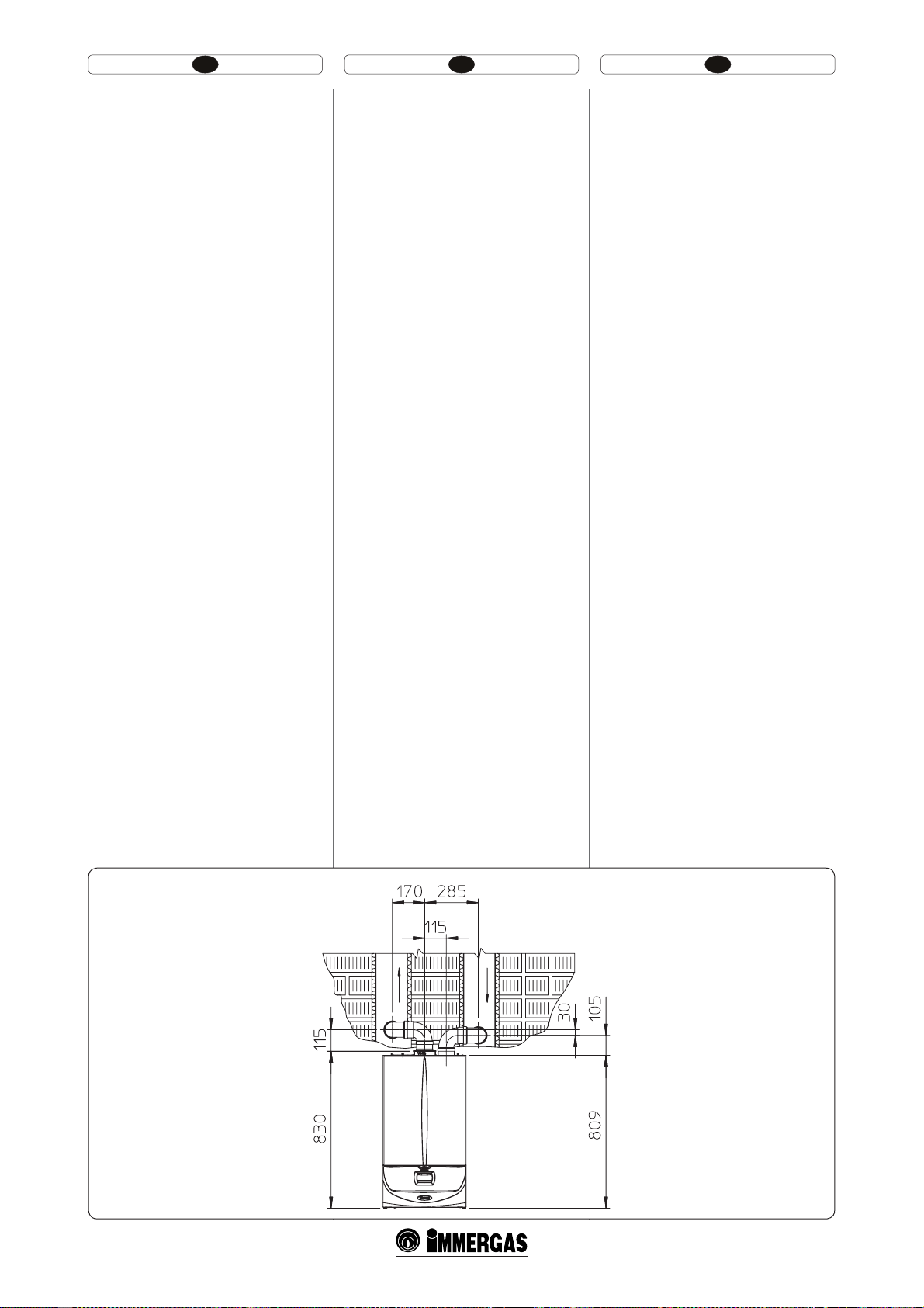
PL CZTR
t (BCBSZUZJOTUBMBDKJ3ZT/BOJFTJPOF
zostały minimalne wymiary gabarytowe instalacji zestawu końcówki rozdzielającej Ø 80/80 w
niektórych warunkach granicznych.
t 1S[FEV˃LJ EMB [FTUBXVSP[E[JFMBKʇDFHP
80/80. Maksymalna długość w linii prostej (bez
zakrętów) w pionie, stosowany do rur zasysania
i odprowadzania Ø 80 to 41 metrów niezależnie
od eksploatacji przy zasysaniu czy odprowadzaniu. Maksymalna długość w linii prostej (z
zakrętem przy zasysaniu i spuście) w poziomie
stosowana do rur zasysania i odprowadzania Ø
80 to 36 metrów niezależnie od eksploatacji przy
zasysaniu czy odprowadzaniu.
N.B.: aby ułatwić odprowadzenie ewentualnego
kondensatu, który tworzy się w przewodzie spustowym wskazane jest pochylenie rur w kierunku
kotła o pochyłości minimalnej 1,5% (Rys. 1-22). Podczas montażu przewodów Ø 80, co 3 metry należy
zainstalować opaskę przerywającą z kołkiem.
t .POUBKNFTBGFMFSJ ʰFLJM #B[ TOSMBZD
durumlarda Ø 80/80 ayrıştırma terminal
setinin montajı için asgari mesafe boyutları
verilmiştir.
t BZSʰUSNBTFUJJÎJOV[BUNBUBIMJZF
ve emiş boruları için düz olarak (dirseksiz)
azami dikey uzunluk, bunların emiş veyahut da
tahliyede kullanılmalarından bağımsız olarak,
41 metredir. Ø 80 tahliye ve emiş boruları için
düz olarak (emiş ve tahliye dirsekli) azami yatay
uzunluk, bunların emiş veyahut da tahliyede
kullanılmalarından bağımsız olarak, 36 metredir.
Not : tahliye kanallarında oluşması muhtemel kondensasyonun dışarı atılımının kolaylaştırılabilmesi
için boruların kombi istikametinde asgari %1.5
eğimli olması gerekmektedir (şekil 1-22). Ø 80
boruların montajı esnasında, her 3 metrede bir
dübellemek suretiyle tutucu kelepçe kullanılması
gerekmektedir.
t *OTUBMBʊOÓPCWPEPWÏSP[NʏSZ0CS6WF-
deny jsou minimální obvodové rozměry instalace koncové rozdělovací soupravy o průměru
80/80 v mezních podmínkách.
t 1SPEMVäPWBDÓLVTZQSPEʏMJDÓ TPVQSBWVP
průměru 80/80.
Maximální přímá délka (bez ohybů) vertikálně
použitelná pro nasávací a výfukové roury o
průměru 80 je 41 metrů nezávisle na tom, zda
jsou použity pro nasávání či výfuk. Maximální
přímá délka (s kolenem u nasávání a výfuku)
horizontálně použitelná pro nasávací a výfukové
roury o průměru 80 je 36 metrů nezávisle na tom,
zda jsou použity pro nasávání či výfuk.
Poznámka: Abyste napomohli eliminaci případného
kondenzátu, který se tvoří ve výfukovém potrubí je
nutné naklonit potrubí ve směru kotle s minimálním sklonem 1,5% (Obr. 1-22). Při instalaci potrubí
o průměru 80 je nutné každé tři metry instalovat
tahový pás s hmoždinkou.
34
C43
1-21
Page 22
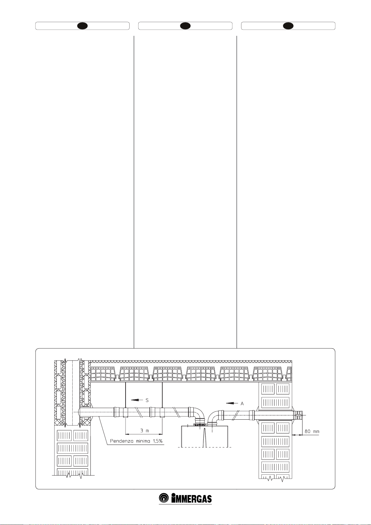
HU IERO
t )FMZT[àLTÏHMFU"[ ÈCSÈO ÈCSB B
Ø80/80mm-es szétválasztott szerelési készlet
felszereléséhez szükséges minimális helyigényre
vonatkozó méretek láthatóak.
t 5PMEØFMFNFLBNNFTT[ÏUWÈMBT[UPUUT[F-
relési készlethez. A függőleges maximális hossz
(könyökidomok nélkül) Ø80 mm-es égéslevegőfüstelvezető csöveknél 41 m, melyből 40 m az
égéslevegő és 1 m a füstelvezető cső. A legtöbb
használható rektilinea hosszúság függőlegesen
az égéslevegő csöveknek és a Ø 80-as füstgáz
csöveknek (égéslevegő és füstgáz könyökkel)
36 méter, attól függetlenül, hogy ezeket az
égéslevegőre vagy a füstgázra használják.
MEGJ.: az esetenként, kieresztő csőben keletkezett kondenz eltűntetését elősegítendő dőltse
meg a csöveket a kazán felé, 1,5 minimális
dőlésszögben (1-22 ábr.). A Ø 80-as vezetékek beszerelése alatt minden 3 méterben egy törésmentes
szigetelőszalagot kell felhelyezni csőbilinccsel.
t 4QBʴJJEFJOTUBMBSF·OĕHVSʅ'JHTVOUUSF-
cute măsurile pentru spaţiile minime de instalare
a kitului terminal separator Ø 80/80 în anumite
condiţii limită.
t 1SFMVOHJUPBSFQFOUSVLJU TFQBSBUPS
Lungimea maximă rectilinie (fără curbe) pe
verticală, utilizabilă pentru tuburile de aspirare şi
evacuare Ø80 este de 41 metri din care 40 metri
indiferent dacă sunt utilizate pentru aspirare sau
evacuare. Lungimea maximă rectilinie (cu curba
de aspirare şi evacuare) pe orizontală utilizabilă
pentru tuburile de aspirare şi evacuare Ø 80 e
de 36 metri indiferent dacă sunt utilizate pentru
aspirare sau evacuare.
N.B.: pentru a favoriza eliminarea eventualei ape de
condensare care se formează pe ţeava de evacuare
ţevile trebuie înclinate în direcţia cazanului cu o
înclinare minimă de 1,5% (Fig. 1-22). În timpul
instalării conductelor Ø 80 e necesar să instalaţi
la ecare trei metri un inel de întrerupere traseu
cu diblu.
t *OTUBMMBUJPODMFBSBODF'JHćFNJOJNVN
installation clearance measurements of the Ø
80/80 separator terminal kit have been stated in
some limit conditions.
t &YUFOTJPOTGPSTFQBSBUPSLJUćFNB-
ximum vertical straight length (without bends)
that can be used or Ø 80 intake and exhaust pipes
is 41 metres, independently to whether they
are used for intake or exhaust. e maximum
horizontal straight length (with bend in suction
and in exhaust) hat can be used or Ø 80 intake
and exhaust pipes is 36 metres independently to
whether they are used for intake or exhaust.
N.B.: to favour the removal of possible condensate
forming in the exhaust pipe, tilt the pipes towards
the boilers with a min. slope of 1.5%. (Fig. 1-22).
When installing the Ø 80 ducts, a section clamp
with pin must be installed every 3 metres.
35
C83
1-22
Page 23
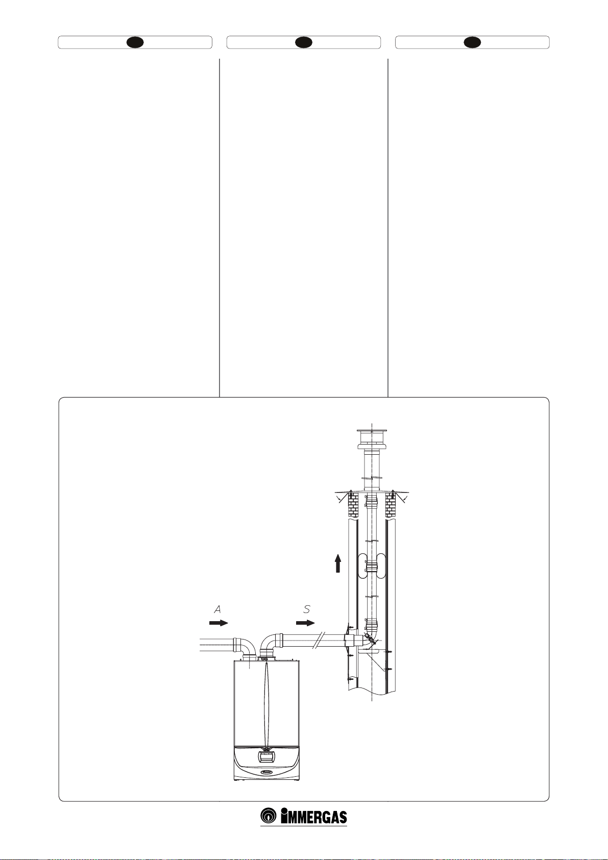
HU IERO
t #23 típusú nyílt kamrás és kényszer huzatos
kazán kiépítése.
A berendezés beszerelhető az épületekbe B
dalitásban; minden eshetőségre, ajánlatos az összes
érvényes nemzeti és helyi műszaki szabályokat és
jogszabályokat betartani.
- A B típusú nyílt kamrás kazánokat nem lehet
olyan helyiségekbe telepíteni, ahol kereskedelmi,
kézműves vagy ipari tevékenységet végeznek,
és ahol gőzök vagy illóanyagok (pl.: savak,
ragasztók, festékek, oldószerek, üzemanyagok
gőzei) valamint porok (pl.: fafeldolgozás pora,
szén-, cementpor stb.) fejlődhetnek, melyek a
készülék elemeit károsíthatják, és veszélyeztethetik működését.
1.10 A MEGLÉVŐ KÉMÉNYEK KIBÉLELÉSE.
A kibélelés egy olyan művelet, amelynek során
egy rendszer felújítása során és egy vagy több új
megfelelő vezetékek beszerelésével egy új, a gázberendezés égéstermékeinek kiengedésére való
rendszert lehet megvalósítani egy már meglévő
kéménytől (vagy egy füstcső), vagy egy műszaki
nyílástól kiindulva (1-23 ábr.). Bélelésre a gyártó
tanúsítványában erre alkalmasként minősített
csőszerelési elemeket kell felhasználni, a gyártó
által megszabott szerelési és használati utasításnak
valamint a jogszabályoknak megfelelően.
Immergas bélelési rendszer. A Ø60-as kemény és
Ø80-as rugalmas“Zöld szériájú” kibélelési rendszereket kizárólag hártartási használatra és az Immergas
kondenzációs kazánjai számára kell alkalmazni.
23
mo-
t $POĕHVSBʴJFUJQ#
forţat.
Aparatul poate instalat în interiorul ediciilor
în modalitatea B
recomandă respectarea tuturor normelor tehnice,
regulilor tehnice şi reglementărilor în vigoare,
naţionale şi locale.
- Centralele cu cameră deschisă tip B nu trebuie să
e instalate în spaţii unde se desfăşoară activităţi
comerciale, artizanale sau industriale în care se
utilizează produse în măsură să emane vapori sau
substanţe volatile (de ex. Vapori de acizi, adezivi,
vopsele, solvenţi, combustibili etc.), dar şi puberi
(de exemplu puberi derivate din prelucrarea
lemnului, pubere de carbon, de ciment) care ar
putea rezulta dăunătoare pentru componentele
aparatului şi ar putea compromise funcţionarea
acestuia.
1.10 INTUBAREA CĂMINELOR EXISTENTE.
Intubarea este o operaţiune prin care, în cadrul
restructurării unui sistem şi prin introducerea
uneia sau mai multor conducte corespunzătoare, se
realizează un sistem nou pentru evacuarea produselor de combustie ale unui aparat pe gaz, pornind
de la un cămin existent (sau de la un coş pentru
fum) sau de la oriciu tehnic (g. 1-23). Pentru
intubare trebuie să e utilizate conducte declarate
corespunzătoare în scopul constructorului, urmând
modalităţile de instalare şi de utilizare indicate de
constructor şi normativele.
Sistem incubare Immergas. Sistemele de intubare
Ø60 rigid şi Ø80 exibil ”Serie verde” trebuie să
e utilizate doar pentru uz casnic şi cu cazane cu
condensare Immergas.
cu cameră deschisă şi tiraj
23
;în această eventualitate, se
23
t $POGJHVSBUJPOUZQF#
forced draught.
e appliance can be installed inside buildings in
B
mode; in this eventuality, all technical rules,
23
and national and local regulations in force, must
be complied with.
- Type B open chamber boilers must not be
installed in places where commercial, artisan
or industrial activities take place, which use
products that may develop volatile vapours or
substances (e.g. acid vapours, glues, paints, solvents, combustibles, etc.), as well as dusts (e.g.
dust deriving from the working of wood, coal
nes, cement, etc.), which may be damaging for
the components of the appliance and jeopardise
functioning.
1.10 DUCTING OF EXISTING FLUES.
Ducting is an operation through which, within
the context of restructuring a system and with the
introduction of one or more special ducts, a new
system is executed for evacuating the fumes of a
gas appliance, starting from an existing ue (or a
chimney) or a technical hole (Fig. 1-23). Ducting
requires the use of ducts declared to be suitable
for the purpose by the manufacturer, following
the installation and user instructions, provided
by the manufacturer, and the requirements of the
standards.
Immergas ducting system. The Ø60 rigid and
Ø80 exible “Green Range” ducting systems must
only be used for domestic use and with Immergas
condensing boilers.
open chamber and
23
C83
37
1-23
Page 24

HU IERO
Minden esetben, a kibélelési műveletek során be
kell tartani az érvényben levő műszaki jogszabályok és előírások szerinti útmutatásokat; főként a
munkálatok végeztével és a kibélelt rendszer beüzemelésekor elő kell állítani a jótállási igazolást. A
tervezet vagy a műszaki jelentés útmutásait be kell
tartani, az érvényes törvénykezések és műszaki
jogszabályok által előírt esetekben. A rendszer és
a rendszer alkotóelemei rendelkeznek a műszaki
érvényességgel, amennyiben:
- átlagos éghajlati és környezeti feltételek között
kerülnek használatra, amint azokat az érvényes
törvények leszögezik (nincs füst, a rendes termozikai vagy vegyi feltételeket befolyásolni képes
por vagy gáz hiánya; standard intervallumokat
jelentő, naponta váltakozó hőmérsékletek jelenléte, stb.).
- A beszerelés és a karbantartás a gyártó által
megadott útmutatások szerint történnek és az
érvényes jogszabályok előírásai szerint.
- A Ø60 kemény vízszintes bélelő megengedett
hossza 22 m-rel egyenlő. Ezt a hosszúságot a Ø
80-as komplett égéslevegő végelem, 1m Ø 80-as
füstgáz cső és a két, akazán kimenetelénél levő
90° Ø 80-as könyök adja.
- A Ø80 rugalmas vízszintes bélelő megengedett
hossza 30 m-rel egyenlő. Ezt a hosszúságot a Ø
80-as komplett égéslevegő végelem, 1m Ø 80-as
füstgáz cső és a két, akazán kimenetelénél levő
90° Ø 80-as könyök és a kazánban / műszaki
nyílásban a rugalmas cső két cserélője adja.
1.11 FÜST ELVEZETÉSE KÉMÉNYBE/
KÉMÉNYCSŐBE.
A füstgázt nem szabad hagyományos gyűjtő
rendszerű kéménybe vezetni. A füstgáz elvezetésére
az L.A.S. típusú gyűjtőkémény használható. A gyűjtő
füstcsöveket és a kombinált füstcsatornákat kizárólag C típusú berendezésekhez kell ugyanakkor
csatlakoztatni és ugyanolyan fajtájúhoz (kondenzációs), olyan névleges termikus teljesítménnyel
rendelkezőekhez, amelyek 30% -al több értékkel
nem különböznek egymástól, a maximális csatlakoztatáshoz képest és ugyanazzal az üzemanyaggal
működnek. Az ugyanahoz a gyűjtőkéményhez
vagy kombinált füstcsövekhez csatlakoztatott berendezések termouidodinamikus jellemzői (füst
maximális teljesítmény, a szénnitrát %, a nedvesség
%, stb.) nem különbözhetnek egymástól több mint
10% , a csatlakoztatott kazán átlagához képest. A
füstcsatornákat úgy kell kialakítani, hogy azok
megfeleljenek a szakképzett személyek által végzett
számítási módszernek, és a szabvány előírásainak.
Annak a kéménynek vagy füstcsatornának a keresztmetszetének, melybe a füstelvezető cső bekötésre
kerül, meg kell felelnie a szabvány előírásainak.
1.12 FÜSTCSŐRENDSZER, KÉMÉNY ÉS
KÉMÉNYFEJEK.
Az égéstermékek elvezetésére szolgáló
füstcsőrendszereknek, kéményeknek és kéményfejeknek meg kell felelniük az alkalmazható szabályok előírásainak.
Szívó végelemek elhelyezése.A szívó végelemek-
nek:
- az épület külső falán kell elhelyezkedniük;
- úgy kell elhelyezkedniük, hogy a távolságok
betartsák a hatályos műszaki szabványokban
meghatározott minimális értékeket.
A füstventilátoros készülékek égéstermék kivezetése tető nélküli, minden oldalról zárt térbe.A tető
nélküli, minden oldalról zárt terekben (szellőzőakna,
belső udvar stb.) megengedett a 4 kW-nál nagyobb
és legfeljebb 35 kW hőteljesítményű füstventilátoros
vagy anélküli gázkészülékek égéstermékének kivezetése, amennyiben az a hatályos műszaki szabványokban meghatározott feltételeknek megfelel.
În orice caz, operaţiunile de intubare trebuie să
respecte prevederile conţinute în normativa şi
legislaţia tehnica în vigoare; în particular, la terminarea lucrărilor şi legat de punerea în funcţiune
a sistemului intubat, va trebui să e completată
declaraţia de conformitate. Vor mai trebui să e
executate indicaţiile din proiect sau din raportul
tehnic, în cazurile prevăzute de norma sau legislativa tehnică în vigoare. Sistemul sau componentele
sistemului au o viaţă tehnică conformă cu normativele în vigoare, cu condiţia:
- să e utilizat în condiţii atmosferice şi ambient ale
medii, aşa cum sunt denite de norma în vigoare (absenţa gazelor arse, pulberilor sau gaz în
măsură să altereze condiţiile normale termozice
sau chimice; existenţa de temperaturi cuprinse
în intervalul standard de variere zilnică, etc.).
- Instalarea şi întreţinerea să e efectuate conform
indicaţiilor furnizate de constructor şi conform
prescrierilor normativei în vigoare.
- Lungimea maximă parcursă a traseului vertical
intubat Ø60 rigid este egal cu 22 m. Această
lungime este obţinută considerând terminalul
complet de aspirare Ø80, 1m de tub Ø80 în evacuare şi curbele la Ø60 la ieşirea din centrală.
- Lungimea maximă parcursă a traseului vertical
intubat Ø80 exibil este egal cu 30 m. Această
lungime este obţinută luând în considerare
terminalul complet de aspirare Ø80, 1 m de tub
Ø80 în evacuare, curbele la 90° Ø80 la ieşirea din
cazan şi cele două schimbări de direcţie a tubului
exibil în interiorului căminului / oriciului
tehnic.
1.11 EVACUAREA GAZELOR ARSE ÎN SI
STEMUL DE EVACUARE GAZE ARSE/
CĂMIN.
Evacuarea gazelor arse nu trebuie să e racordată
la un sistem de evacuare gaze arse colectiv ramicat
de tip tradiţional. Evacuarea gazelor arse poate
legată la un sistem de evacuare gaze arse colectiv
particular, tip LAS. Sistemele de evacuare gaze
arse colective şi coşurile de fum combinate trebuie
în plus să e legate doar cu aparate de tip C şi de
acelaşi tip (condensare) ce au capacităţi termice
nominale ce nu diferă cu mai mult de 30% mai puţin
faţă de maxima racordabilă şi alimentate cu acelaşi
combustibil. Caracteristicile termouidodinamice
(capacitate în masă a gazelor arse, % de anhidridă
carbonică, % de umiditate etc.) a aparatelor racordate la aceleaşi coşuri de fum combinate, nu
trebuie să difere cu mai mult de 10% faţă de cazanul
mediu racordat. Coşurile de fum colective şi cele
combinate trebuie să e expres proiectate urmând
metodologia de calcul şi normele tehnice în vigoare,
de personal tehnic profesional calicat. Secţiunile
căminelor sau coşurile de fum la care se leagă
tubul de evacuare gaze arse trebuie să corespundă
cerinţelor normativelor tehnice în vigoare.
1.12 COŞURI DE FUM, CĂMINE ŞI HORNU
RI.
Coşurile de fum, căminele şi hornurile pentru
evacuarea produselor de combustie trebuie să
corespundă cerinţelor normelor aplicabile.
Poziţionarea terminalelor de tiraj. Ter m inalele
de tiraj trebuie:
- să e situate pe pereţi perimetrici externi ai
ediciului;
- să e poziţionate astfel încât distanţele să respecte
valorile minime din norma tehnică în vigoare.
Evacuarea produselor de combustie a aparatelor
cu tiraj forţat în spaţii închise cu cer liber. În
spaţiile cu cer liber închise pe toate părţile (puţuri
de ventilare, curţi interioare, curţi şi similare) este
permisă evacuarea directă a produselor de combustie a aparatelor cu gaz cu tiraj natural sau forţat
şi capacitate termică de peste 4 până la 35 kW, cu
condiţia să e respectate condiţiile conform normei
tehnice în vigoare.
In any case, ducting operations must respect the
provisions contained in the standard and in current
technical regulations; in particular, the declaration
of conformity must be compiled at the end of work
and on commissioning of the ducted system. e
instructions in the project or technical report
must likewise be followed, in cases provided for
by the standard and current technical regulations.
e system or components of the system have a
technical life complying with current standards,
provided that:
- it is used in average atmospheric and environmental conditions, according to current regulations (absence of fumes, dusts or gases that can
alter the normal thermophysical or chemical
conditions; existence of temperatures coming
within the standard range of daily variation,
etc.).
- Installation and maintenance must be performed
according to the indications supplied by the manufacturer and in compliance with the provisions
in force.
- e max. possible length of the Ø 60 exible
ducting vertical section is equal to 22 m. is
length is obtained considering the complete Ø
80 exhaust terminal, 1m of Ø 80 pipe in exhaust,
two 90° Ø 80 bends at boiler outlet.
- e max. possible length of the Ø 80 exible
ducting vertical section is equal to 30 m. is
length is obtained considering the complete
exhaust terminal, 1m of Ø 80 pipe in exhaust, two
90° Ø 80 bends at boiler outlet for connecting to
the ducting system and two direction changes of
the exible tube inside the ue/technical hole.
1.11 FUME EXHAUST TO FLUE/CHIMNEY.
Flue exhaust does not necessarily have to be connected to a branched type traditional ue. Flue exhaust
can be connected to a special LAS type multiple ue.
e multiple ues and the combined ues must also
only be connected to type C appliances of the same
type (condensing), having nominal heat inputs that
do not dier by more than 30% less with respect to
the maximum that can be attached and powered by
the same fuel. e thermo-uiddynamic features
(ue ow rate, % of carbon dioxide, % humidity
etc....) of the appliances attached to the same mul-
tiple ues or combined ues, must not dier by
more than 10% with respect to the average boiler
attached. Multiple and combined ues must be specially designed according to the calculation method
and requirements of the standards, by professionally
qualified technical personnel. Chimney or flue
sections for connection of the exhaust pipe must
comply with standard requisites in force.
1.12 FLUES, CHIMNEYS AND CHIMNEY
CAPS.
The flues, chimneys and chimney caps for the
evacuation of combustion products must be in
compliance with applicable standards.
Positioning the dra terminals. Dra terminals
must:
- be installed on external perimeter walls of the
building;
- be positioned according to the minimum distances specied in current technical standards.
Fume exhaust of forced draught appliances in
closed open-top environments. In spaces closed on
all sides with open tops (ventilation pits, courtyards
etc.), direct fume exhaust is allowed for natural or
forced draught gas appliances with a heating power
range from 4 to 35 kW, provided the conditions as
per the current technical standards are respected.
39
Page 25

HU IERO
1.13 A BERENDEZÉS FELTÖLTÉSE.
A kazán csatlakoztatását követően indítsuk el a
rendszer feltöltését a víztöltő csapon keresztül (1-25
ás 2-8 ábrák). A feltöltést lassan kell végezni, hogy
a vízben lévő levegőbuborékok összegyűlhessenek
és eltávozhassanak a kazán és a fűtési rendszer
légtelenítő szelepein keresztül.
A kazán keringető szivattyúján beépített önműködő
légtelenítő szeleppel rendelkeznek. Ellenőrizzük,
hogy a légtelenítő szelepek sapkája kellően meg
van-e lazítva. Nyissuk meg a radiátorok légtelenítő
szelepeit.
A radiátorok légtelenítő szelepeit akkor lehet elzárni, amikor már csak víz folyik belőlük.
A víztöltő csapot akkor kell elzárni, amikor a kazán
nyomásmérője kb. 1,2 bar nyomást mutat.
Megj.: e műveletek során a keringető szivattyút
a kezelőpanelen találhatófőkapcsoló segítségével
szakaszosan működtessük. A keringető szivattyúkat a motor működtetése közben az elülső dugó
lecsavarásával légtelenítsük. A művelet végeztével
csavarjuk vissza a zárósapkáját.
1.14 KONDENZGYŰJTŐ SZIFONOK ÚJRA
TÖLTÉSE.
A kazán első begyújtásakor megtörténhet, hogy a
kondenzcsőből égéstermékek távoznak, ellenőrizze
egy pár perces működés után, hogy a konenzcsőből
nem távozik több égéstermékfüst. Ez azt jelenti,
hogy a szifon a megfelelő magasságig telített kondenzzel, amely nem engedi meg a füst távozását.
1.15 A GÁZBERENDEZÉS BEÜZEMELÉSE.
A gázcsatlakozás beüzemelésekor szükséges
teendők:
- nyissuk ki az ablakokat és az ajtókat;
- kerüljük szikra vagy nyílt láng használatát;
- ürítsük ki a gázcsövekben maradt levegőt;
- ellenőrizzük a fogyasztói gázhálózat gáztömör-
ségét a jogszabályok által előírt módon.
1.16 A KAZÁN BEÜZEMELÉSE
BEGYÚJTÁS.
A törvény által előírt szabványossági nyilatkozat
kiállításához a kazán beüzemelésekor a következő
kötelezettségeknek kell eleget tenni:
- ellenőrizzük a gázrendszer tömörségét a jogs-
zabályok által előírt módon;
- ellenőrizzük, hogy a rendelkezésre álló gáztípus
megegyezik azzal, amelyre a készülék be van állítva;
- gyújtsuk be a kazánt és ellenőrizzük az égés
megfelelő voltát;
- ellenőrizzük, hogy a csatlakozó gázrendszer
hozama és a nyomásértékek megfelelnek-e a
műszaki adatoknál feltüntetett értékeknek (lásd
3.18. paragrafus);
- ellenőrizzük, hogy gázhiány esetén a biztonsági
elzáró szelep megfelelően működik-e, és mennyi
idő alatt lép működésbe;
- ellenőrizze a kazánon és a kazánban levő
főelosztó beavatkozását;
- ellenőrizzük a kazán szívó/kiürítő koncentrikus
végelem (ha van) hibátlan működését.
Ha a fenti ellenőrzések közül akár csak egy is pozitív
eredményt ad, a kazán nem üzemelhető be.
Megj : akazán beüzemelését csakis szakember
végezheti el. A készülék jótállási ideje a sikeres beüzemelés időpontjától kezdődik.
Az elvégzett beüzemelés igazolása és a Jótállási jegy
az ügyfélnek kiadásra kerül
.
1.13 REUMPLEREA INSTALAŢIEI .
După racordarea centralei, umpleţi instalaţia prin
robinetul de umplere (Fig. 1-25 şi 2-8). Umplerea se
execută lent pentru a permite bulelor de aer din apă
să se elibereze şi să iasă prin oriciile de răsuare
ale centralei şi a instalaţiei de încălzire.
Centrala are incorporată o supapă de răsuare
automată aşezată pe circulator. Controlaţi să e
desfăcut capacul. Deschideţi supapele de răsuare
ale radiatorilor.
Supapele de răsuare ale radiatorilor trebuie închise
când din ele iese numai apă.
Robinetul de umplere se închide când manometrul
de centrală indică circa 1,2 bari.
N.B.: în timpul acestor operaţiuni puneţi în
funcţiune pompa de circulare la intervale, acţionând
asupra selectorului general aşezat pe bord. Permiteţi
răsuflarea pompei de circulare deşurubând dopul anterior şi menţinând motorul în funcţiune.
Reînşurubaţi dopul după efectuarea operaţiunii.
1.14 UMPLEREA SIFONULUI DE COLECTA
RE APĂ DE CONDENSARE.
La prima pornire a centralei se poate întâmpla ca
din evacuarea apei de condensare să iasă produse
de combustie, vericaţi ca după o funcţionare de
câteva minute de la evacuarea apei de condensare
să nu mai iasă gaze arse de combustie. Acest lucru
înseamnă că sifonul s-a umplut la o înălţime corectă
cu apă de condensare pentru a nu permite trecerea
gazelor arse.
1.15 PUNERE ÎN FUNCŢIUNE A
INSTALAŢIEI GAZ.
Pentru punerea în funcţiune a instalaţiei e necesar
să:
- deschideţi ferestrele şi uşile;
- evitaţi prezenţa de scântei şi ăcări libere;
- procedaţi la eliminarea aerului din ţevi;
- vericaţi etanşeitatea instalaţiei interne conform
indicaţiilor furnizate de normă.
1.16 PUNERE ÎN FUNCŢIUNE A CENTRA
LEI PORNIRE.
În scopul emiterii Declaraţiei de Conformitate
prevăzute de Lege trebuie îndeplinite următoarele
cerinţe pentru punerea în funcţiune a centralei:
- vericaţi etanşeitatea instalaţiei interne conform
indicaţiilor furnizate de normă;
- vericaţi ca gazul utilizat să corespundă cu acel
pentru care centrala a fost prestabilită ;
- porniţi centrala şi vericaţi aprinderea corectă;
- vericaţi ca puterea gazului şi presiunile respec-
tive să e conforme cu cele indicate în manual
(Parag. 3.18);
- vericaţi intervenţia dispozitivului de siguranţă
în caz de lipsă a gazului şi timpul relativ de
intervenţie;
- vericaţi intervenţia întrerupătorului general
aşezat în amonte faţă de centrală şi în centrală;
- vericaţi ca terminalul concentric de aspirare /
evacuare (dacă e prezent), să nu e obturat.
Dacă şi doar unul din aceste controale rezultă negativ, centrala nu trebuie pusă în funcţiune.
N.B.: vericarea iniţială a centralei trebuie să e
efectu ată de un tehnici an abilitat. Garanţi a centralei
începe de la data vericării acesteia. Certicatul de
vericare şi garanţie este emis utilizatorului.
1.13 SYSTEM FILLING.
Once the boiler is connected, proceed with system
lling via the lling valve (Fig. 1-25 and 2-8). Filling is performed at low speed to ensure release of
air bubbles in the water via the boiler and heating
system vents.
e boiler has a built-in automatic venting valve
on the circulator. Check if the cap is loose. Open the
radiator air vent valves.
Close radiator vent valves only when only water
escapes from them.
Close the lling valve when the boiler manometer
indicates approx 1,2 bar.
N.B.: during these operations start/up the circulation pump at intervals, acting on the main
switch positioned on the control panel. Vent t h e
circulation pump by loosening the front cap and
keeping the motor running. Re-tighten the cap aer
the operation.
1.14 FILLING CONDENSATE COLLECTION
TRAP.
On rst lighting of the boiler fumes may come out
the condensate drain; aer a few minutes’ operation
check that fumes no longer come out. is means
that the trap is lled with condensate to the correct
level preventing the passage of fumes.
1.15 GAS SYSTEM STARTUP.
To start up the system proceed as follows:
- open windows and doors;
- avoid presence of sparks or naked ames;
- bleed all air from pipelines;
- check that the internal system is properly sealed
according to specications.
1.16 BOILER STARTUP LIGHTING.
For issue of the Declaration of Conformity provided
for by Italian Law, the following must be performed
for boiler start-up:
- check that the internal system is properly sealed
according to specications;
- ensure that the type of gas used corresponds to
boiler settings;
- switch the boiler on and ensure correct igni-
tion;
- make sure that the gas ow rate and relevant
pressure values comply with those given in the
manual (Parag. 3.18);
- ensure that the safety device is engaged in the
event of gas supply failure and check activation
time;
- check activation of the main switch located
upstream from the boiler and in the boiler;
- check that the concentric intake/exhaust termi-
nal (if tted) is not blocked.
e boiler must not be started up in the event of
failure to comply with any of the above.
N.B.: e boiler preliminary check must be carried
out by a qualied technician. e boiler warranty is
valid as of the date of testing.
e test certicate and warranty is issued to the
user.
41
Page 26

HU IERO
1.17 KERINGETŐ SZIVATTYÚ.
Az “Victrix Superior kW X” kazánok gyárilag
beépített, 3 állásos elektromos szabályozású
keringetővel rendelkeznek, amely több mint az
automatikus sebesség. Az automatikus sebesség
dönti el a keringető legalkalmasabb beállítását a a
berendezés szállítása és visszacsatlakozása között
mért ∆T alapján. (3.8 bekezdés “P57” paraméteren).
A keringető rendelkezik kondenzátorral.
Szivattyú esetleges kioldása. Amennyiben hosszabb leállás után a keringető nem működik, le kell
csavarni az első védősapkát, és egy csavarhúzóval
megpörgetni a motor tengelyét. Különös óvatossággal járjon el ennél a műveletnél, hogy ne károsítsa
a motort.
1.18 KÜLÖN KÉRÉSRE SZÁLLÍTOTT KÉ
SZLETEK.
t &M[ÈSØDTBQLÏT[MFUGFMàMWJ[THÈMØT[ʶSʩWFMWBHZ
anélkül (megrendelésre). A kazán gyári kialakítása lehetővé teszi elzáró csapok felszerelését a
csatlakozó blokk előremenő és visszatérő csöveire. Ez a készlet igen hasznosnak bizonyulhat
a karbantartás során, mivel így lehetővé válik,
hogy csak a kazánt kelljen vízteleníteni és ne a
teljes vezetékrendszert, valamint a szűrős verzió
megőrzi működési jellemezőit a felülvizsgáló
szűrőnek köszönhetően.
t ;ØOÈTCFSFOEF[ÏTLÚ[QPOULÏT[MFU LÏSÏTSF
Amennyiben a berendezést több zónára fel
szeretnék osztani (legtöbb háromra), hogy
független szabályozókkal legyen külön ellátva,
és hogy minden zónában a megfeleő vízhozam
maradjon, az Immergas zónás berendezéskészletet szállít külön kérésre.
t ,àMTʩ ÏHFUʩ FHZTÏHIF[DTBUMBLP[BUØLÏT[MFU
(kérésre). Amennyiben a környezeti fűtés mellett, használati meleg víz előállítására is szükség
ven, az Immergas kérésre egy, minden szükséges
elemet tartalmazó készletet szállít, amellyel a
kazánt egy külső forraló egységre lehet alkalmazni.
t 1PMJGPT[GÈUBEBHPMØ LÏT[MFU LÏSÏTSF"QPMJGP-
szfát adagoló csökkenti a mészkőlerekódások
kialakulásának veszélyét, megörizve a termikus
cserélő és meleg viz termelő eredeti állapotát.
A kazánt lehet a polifoszfát adagoló készlettel
használni.
t 3FMÏLÈSUZB LÏSÏTSF"LB[ÈOPOMFIFUFHZ
relékártyát használni, amely lehetővé teszi a
berendezés jellemzőinek kitágítását, s ilymódon
a működési lehetőségeket.
t 'FEʩLÏT[MFULÏSÏTSF"NFOOZJCFOSÏT[MFHFTFO
védett külső térbe szereljük be a közvetlen
égéslevegővel védett kazánt, kötelező felszerelni
a megfelelő felső védőfedőt a kazán megfelelő
működése érdekéban, és, hogy védett legyen az
éghajlati hatásoktól.
A fenti kiegészítő készleteket a gyártó kompletten,
szerelési és használati útmutatóval együtt szállítja.
1.17 POMPĂ DE CIRCULARE .
Centralele ” Victrix Superior kW X” sunt furnizate
cu circulator incorporat cu reglator electric de viteză
cu trei poziţii plus viteza automată. Viteza automată
decide setarea mai adecvată a circulatorului în baza
∆T măsurat între turul şi returul instalaţiei (Parag.
3.8 la parametrul “P57”). Circulatorul este deja
dotat cu condensator.
Eventuala deblocare a pompei. Dacă după o
perioadă lungă de inactivitate circulatorul este
blocat este necesar să deşurubaţi dopul anterior şi
să rotiţi cu o şurubelniţă arborele motor. Efectuaţi
operaţiunea cu extremă atenţie pentru a nu-i
provoca daune.
1.18 KITURI DISPONIBILE LA CERERE.
t ,JUVSJSPCJOFUFJOUFSDFQUBSFJOTUBMBʴJFDV TBV
fără ltru de control (la cerere). Centrala este
prevăzută pentru instalarea robinetelor de
interceptare instalaţie de inserat pe tuburile de
tur şi retur ale grupului de racord. Acest kit este
foarte util în momentul întreţinerii deoarece
permite golirea doar a cazanului fără a trebui
golită întreaga instalaţie, în plus versiunea cu
ltru păstrează caracteristicile de funcţionare
ale centralei datorită ltrului de control.
t ,JUDFOUSBMʅJOTUBMBʴJJQF [POʅMBDFSFSF·O
cazul în care se doreşte divizarea instalaţiei de
încălzire în mai multe zone (maxim trei) pentru
a le deservi separat cu reglări independente şi
pentru a menţine ridicată puterea apei pentru
ecare zonă, Immergas furnizează la cerere kitul
instalaţii pe zonă.
Kit cuplare unitate erbător externă (la cerere).
t
În cazul în care este necesară producerea de apă
caldă menajeră în afară de încălzirea mediului,
Immergas furnizează la cerere un kit compus
din cele necesare pentru adaptarea centralei la
o unitate erbător externă.
t ,JUEP[BUPSQPMJGPTGBʴJ MB DFSFSF %P[BUPSVM
de polifosfaţi reduce formarea de incrustaţii
calcaroase, menţinând în timp condiţiile originale de schimb termic şi producere de apă
caldă menajeră. Centrala este prevăzută pentru
aplicarea kitului dozator de polifosfaţi.
t 1MBDʅSFMFVMBDFSFSF$FOUSBMBFTUFQSFWʅ[VUʅ
pentru instalarea unei plăci releu ce permite
amplicarea caracteristicilor aparatului şi deci
posibilitatea de funcţionare.
t ,JUBDPQFSJSFMB DFSFSF·ODB[ EF JOTUBMBSFÔO
exterior în loc parţial protejat cu aspirare directă
a aerului este obligatoriu să montaţi capacul
superior de protecţie corespunzător, pentru
funcţionarea corectă a centralei şi pentru a o
proteja de intemperii.
Kiturile de mai sus sunt furnizate dotate cu manual
de instrucţiuni pentru montare şi utilizare.
1.17 CIRCULATION PUMP.
e “Victrix Superior kW X” Range of boilers is
supplied with a built-in circulation pump with
3-position electric speed control plus automatic
speed. e automatic speed decides the most suitable setting of the pump on the basis of ∆T measured
between system delivery and return (Par. 3.8 at
parameter “P57”). e circulation pump is already
tted with a capacitor.
Pump release. If, aer a prolonged period of inactivity, the circulation pump is blocked, unscrew
the front cap and turn the motor sha using a
screwdriver. Take great care during this operation
to avoid damage to the motor.
1.18 KITS AVAILABLE ON REQUEST.
t TZTUFNTIVUPČWBMWF LJUT XJUIPSXJUIPVUJO-
spectionable lter (on request) e boiler is
designed for installation of system shuto valves
to be placed on delivery and return pipes of the
connection assembly. is kit is very useful for
maintenance because it allows to empty just the
boiler without having to empty the entire system.
Moreover, the version with lter preserves the
functioning characteristics of the boiler thanks
to its inspectionable lter.
t 4ZTUFN[POFDPOUSPMVOJU ,JUPOSFRVFTU*G
the heating system is to be divided into several
zones (max. three) in order to interlock them
with separate adjustments and to keep water ow
rate high for each zone, Immergas supplies zone
system kits by request.
External storage unit coupling kit (on request). If
t
the production of domestic hot water is required
as well as heating, on request Immergas supplies
a kit made up from that necessary for the adaptation of the boiler to an external storage unit.
t 1PMZQIPTQIBUFEJTQFOTFS LJU PO SFRVFTU ćF
polyphosphate dispenser reduces the formation
of lime-scale and preserves the original heat
exchange and domestic hot production water
conditions. e boiler is prepared for application
of the polyphosphate dispenser kit.
t 3FMBZCPBSEPOSFRVFTUćFCPJMFSJTQSFQBSFE
for the installation of a relay card that allows
to increase the features of the appliance and
therefore functioning possibilities.
t $PWFSLJUPOSFRVFTU*GJOTUBMMFEPVUEPPSTJOB
partially protected place with direct air intake,
it is compulsory to mount the appropriate upper
protection cover for the correct functioning of
the boiler and to protect it from adverse weather
conditions.
e above kits are supplied complete with instructions for assembly and use.
43
Page 27
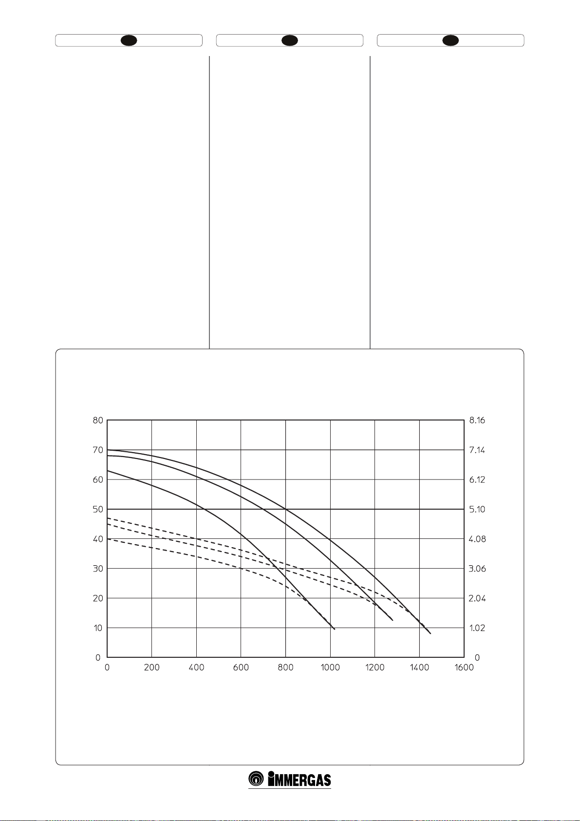
HU IERO
Fűtési körben rendelkezésre álló térfogatáram.
Jelmagyarázat (1-24 ábra):
A = adott túlsúly a hármas sebességben levő
berendezésen, kizárt by-pass (szabályozó
csavarok teljesen becsavarva)
B = túlsúly a kettes sebességben levő be-
rendezésen, kizárt by-pass (szabályozó
csavarok teljesen becsavarva)
C = túlsúly az első sebességben levő berendezé-
sen, kizárt by-pass (szabályozó csavarok
teljesen becsavarva)
D = túlsúly a hármas sebességben levő
berendezésen (csavarok 1,5 fordulattal
becsavarva a teljesen kicsavart szabályozó
csavarokhoz képest)
E = túlsúly a kettes sebességben levő
berendezésen (csavarok 1,5 fordulattal
becsavarva a teljesen kicsavart szabályozó
csavarokhoz képest)
F = túlsúly a első sebességben levő berendezé-
sen (csavarok 1,5 fordulattal becsavarva a
teljesen kicsavart szabályozó csavarokhoz
képest)
Nivel lichid disponibil în instalaţie .
Legenda (Fig. 1-24):
A = Nivel lichid disponibil în instalaţie a treia
viteză cu by pass exclus (şurub de reglare
complet înşurubat)
B = Nivel lichid disponibil în instalaţie pe
viteza a doua cu by pass exclus (şurub de
reglare complet înşurubat)
C = Nivel lichid disponibil în instalaţie la
viteza întâi cu by pass exclus (şurub de
reglare complet înşurubat)
D = Nivel lichid disponibil în instalaţie la
viteza a treia (şurub înşurubat de 1,5 ori
faţă de şurubul de reglare total deşurubat)
E = Nivel lichid disponibil în instalaţie la
viteza a doua (şurub înşurubat de 1,5 ori
faţă de şurubul de reglare total deşurubat)
F = Nivel lichid disponibil în instalaţie la vite-
za întâi (şurub înşurubat de 1,5 ori faţă de
şurubul de reglare total deşurubat)
Total head available to the plant.
Key (Fig. 1-24):
A = Head available to the system on the third
speed with by-pass excluded (adjustment
screws tightened fully home)
B = Head available to the system on the second
speed with by-pass excluded (adjustment
screws tightened fully home)
C = Head available to the system on the rst
speed with by-pass excluded (adjustment
screws tightened fully home)
D = Total head available to the plant on
the third speed (screws tightened by 1.5
revs with respect to the completely loose
adjustment screws)
E = Total head available to the plant on the
second speed (screws tightened by 1.5
revs with respect to the completely loose
adjustment screws)
F = Total head available to the plant on
the rst speed (screws tightened by 1.5
revs with respect to the completely loose
adjustment screws)
Túlsúly (kPa) \ Nivel lichid (kPa) \ Head (kPa)\
O)
2
A
O) \ Head (m H
C
B
2
D
O) \ Nivel lichid (m H
F
E
2
Túlsúly (m H
Hozam (l/h) \ Capacitate (l/h) \ Flow rate (l/h)
45
1-24
Page 28
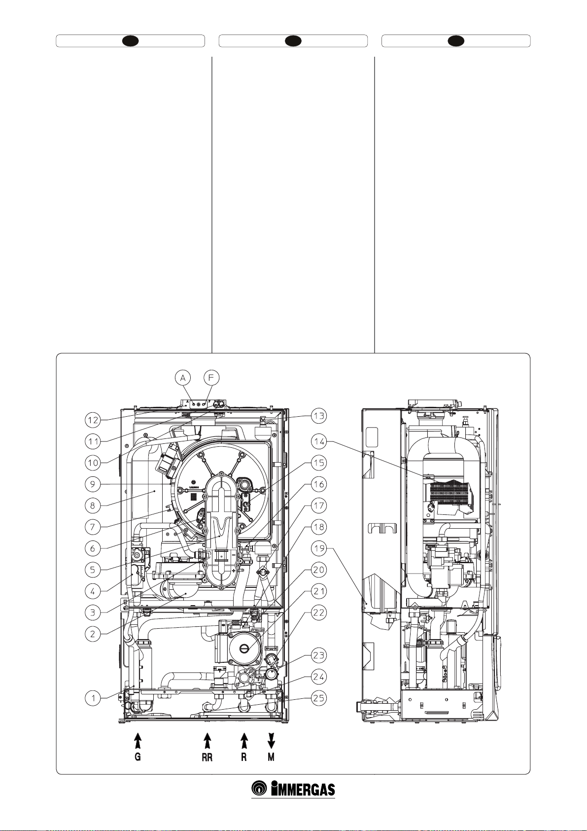
HU IERO
1.19 A KAZÁN RÉSZEI.
Jelmagyarázat (1-25 ábra):
1 - Kondenz ürítő szifon
2 - Ventilátor
3 - Gázfuvóka
4 -Gázszelep
5- Venturik
6 - Felmérési gyertyák
7 - Füsttermosztát
8 - Égéslevvegő cső
9 - Kondenzációs modul
10 - Negatív nyomásjelzésfogó
11 - Pozitív nyomásjelzésfogó
12 - Vételezési aknák (levegő A) – (F füst)
13 - Kézi légáramlás szelep
14 - Égő
15 - Begyújtási gyertyák
16 - Küldő szonda
17 - Biztonsági termosztát
18 - Légáramlás szelep
19 - Berendezés kiterjesztési tartálya
20 - Visszatérő szonda
21 - Kazán keringető
22 - Berendezés nyomásmérője
23 - 3 bar-os biztonsági szelep
24 - Berendezés kiürítő csapja
25 - Berendezés újratöltő csapja
1.19 COMPONENTE CENTRALĂ.
Legendă (Fig. 1-25):
1 - Sifon evacuare apă de condensare
2 - Ventilator
3 - Duză gaz
4 - Supapă gaz
5- Venturi
6 - Bujie de indicare
7 - Termostat gaze arse
8 - Tub aspirare aer
9 - Modul cu condensare
10 - Priză presiune semnal negativ
11 - Priză presiune semnal pozitiv
12 - Puţuri de preluare (aer A) - (gaze arse F)
13 - Valvă evacuare aer manual
14 - Arzător
15 - Bujii de aprindere
16 - Sondă tur
17 - Termostat siguranţă
18 - Supapă evacuare aer
19 - Vas expansiune instalaţie
20 - Sondă retur
21 - Circulator cazan
22 - Presostat instalaţie
23 - Supapă de siguranţă 3 bari
24 - Robinet de golire instalare
25 - Robinet de umplere instalaţie
1.19 BOILER COMPONENTS.
Key (Fig. 1-25):
1 - Condensate drain tap
2-Fan
3 - Gas nozzle
4 - Gas valve
5 – Venturi
6 - Detection electrode
7 - Flue safety thermostat
8 - Air intake pipe
9 - Condensation module
10 - Negative signal pressure point
11 - Negative signal pressure point
12 - Intake points (air A) - (fumes F)
13 - Manual vent valve
14 - Burner
15 - Ignition electrodes
16 - Delivery probe
17 - Safety thermostat
18 - Vent valve
19 - System expansion vessel
20 - Return probe
21 - Boiler pump
22 - System pressure switch
23 - 3 bar safety valve
24 - System draining valve
25 - System lling valve
47
1-25
Page 29

HU IERO
HASZNÁLATI ÉS KARBANTARTÁSI
ÚTMUTATÓ FELHASZNÁLÓ.
2
2.1 TISZTÍTÁS ÉS KARBANTARTÁS.
Figyelem! A fűtési rendszeren legalább évente el kell
végezni a rendes karbantartást (ezzel kapcsolatban,
lásd a szakembereknek szánt rész “a készülék éves
ellenőrzése és karbantartásá”-ra vonatkozó részt),
valamint a nemzeti, regionális vagy helyi hatályos
jogszabályok által előírt energetikai hatékonysági
ellenőrzést.
Ezáltal hosszú ideig változatlanul megőrizhetők
a kazán biztonsági, hatékonysági és működési
jellemzői.
Javasoljuk, hogy a lakóhelyéhez legközelebb eső
szakszervízzel kössön éves karbantartási és tisztítási
szerződést.
2.2 ÁLTALÁNOS TUDNIVALÓK.
Ne tegye ki a fali kazánt konyhai főzőlapokról
felszálló gőzök közvetlen hatásának.
Tilos a kazán használata a gyerekek vagy hozzá nem
értő személyek számára.
A biztonságos működés érdekében ellenőrizzük,
hogy az (esetlegesen meglévő) égéslevegő-füstgáz
koncentrikus végelem kimenete még ideiglenesen
se legyen soha eldugulva.
Teendők a kazán ideiglenes kikapcsolása esetén:
a) víztelenítsük a vízrendszert, ha nem tartalmaz
fagyállót;
b) zárjuk el az elektromos, víz- és gáz tápcsatla-
kozást.
Abban az esetben, ha építési vagy karbantartási
munkálatokra kerül sor a füstelvezető rendszer
közvetlen közelében vagy a kéményben, illetve
tartozékaiban, kapcsoljuk ki a készüléket és a
munkálatok befejezését követően szakemberrel
ellenőriztessük az érintett csövek vagy berendezések
megfelelő működését.
A készülék és alkatrészei tisztításához ne alkalmazzunk gyúlékony anyagot.
Ne hagyjunk gyúlékony anyagot vagy ennek
tartályát abban a helyiségben, ahol a készülék
üzemel.
t Figyelem! Az elektromos árammal működő
részegységek bármelyikének használata során
be kell tartani néhány alapvető szabályt:
- ne érintsük meg a készüléket vizes vagy
nedves kézzel, továbbá ne nyúljunk hozzá,
ha mezítláb vagyunk;
- ne húzzuk meg az elektromos kábeleket, ne
tegyük a berendezést az éghajlati körülményeknek (eső, napsütés, stb.);
- a készülék elektromos tápkábelét a felhasználónak tilos kicserélnie;
- a kábel sérülése esetén kapcsoljuk ki a
készüléket és a kábel cseréjével kizárólag
megfelelő szakmai képesítéssel rendelkező
személyt bízzunk meg;
- Amennyiben több ideig nem használja a keszüléket, kapcsolja le az eletromos ellátásról
a berendezést.
MEGJ.: a display-en jelzett hőmérsékleti értékek
+/- 3°C toleranciájúak a környezeti feltételek miatt,
s nem a kazán okozza ezt.
INSTRUCŢIUNI DE UTILIZARE ŞI
ÎNTREŢINERE UTILIZATOR.
2
2.1 CURĂŢARE ŞI ÎNTREŢINERE.
Atenţie: instalaţiile termice trebuie să e supuse
întreţinerii periodice (în acest sens consultaţi
manualul, în secţiunea dedicată tehnicianului,
punctul referitor la ”control şi întreţinere anuală
a aparatului”) şi vericării periodice a ecienţei
energetice cu respectarea dispoziţiilor naţionale,
regionale sau locale.
Acest lucru permite menţinerea nealterate a caracteristicilor de siguranţă, randament şi funcţionare
ce caracterizează centrala.
Sugerăm stipularea de contracte anuale de curăţare şi
întreţinere cu Tehnicianul dumneavoastră din zonă.
2.2 AVERTISMENTE GENERALE .
Nu expuneţi centrala la vapori direcţi proveniţi din
planurile de erbere.
Interziceţi folosirea centralei de către copii şi persoane nespecializate.
În scopuri de siguranţă vericaţi ca terminalul
concentric de aspirare aer/evacuare gaze arse să nu
e obturat nici măcar provizoriu.
În cazul în care se decide dezactivarea temporară a
centralei., va necesar:
a) să goliţi instalaţia de apă, în cazul în care nu este
prevăzută folosirea de antigel;
b) să întrerupeţi alimentările cu electricitate, ap ă şi
gaz.
În caz de lucrări sau întreţineri de structuri aşezate
în apropierea ţevilor sau dispozitivelor de evacuare a gazelor arse şi accesoriilor acestora, opriţi
aparatul şi la terminarea lucrărilor personalul
profesional calicat va verica ecienţa ţevilor sau
dispozitivelor.
Nu efectuaţi curăţarea aparatului sau a părţilor sale
cu substanţe uşor inamabile.
Nu lăsaţi recipiente sau substanţe inamabile în
locul în care este instalat aparatul.
t Atenţie: utilizarea oricărui component ce
foloseşte energie electrică impune respectarea
unor reguli fundamentale printre care:
- nu atingeţi aparatul cu părţi ale corpului
ude sau umede; nu atingeţi nici cu picioarele
goale;
- nu trageţi cablurile electrice, nu lăsaţi expus
aparatul agenţilor atmosferici (ploaie, soare
etc.);
- cablul de alimentare al aparatului nu trebuie
să e înlocuit de utilizator;
- în caz de avariere a cablului, opriţi aparatul
şi adresaţi-vă exclusiv personalului calicat
profesional pentru înlocuirea acestuia;
- dacă se decide să nu se utilizeze aparatul
pentru o anumită perioadă, este oportun să
dezactivaţi întrerupătorul electric de alimentare.
N.B.: temperaturile indicate pe display au o
toleranţă de +/- 3°C datorată condiţiilor ambientale
care nu se atribuie centralei.
USER AND MAINTENANCE
INSTRUCTIONS USER.
2
2.1 CLEANING AND MAINTENANCE.
Important: the heating plants must undergo
periodical maintenance (regarding this, see in
the section dedicated to the technician, the point
relative to “yearly control and maintenance of the
appliance”) and regular checks of energy eciency in compliance with national, regional or local
provisions in force.
is ensures that the optimal safety, performance
and operation characteristics of the boiler remain
unchanged over time.
We recommend stipulating a yearly cleaning and
maintenance contract with your zone technician.
2.2 GENERAL WARNINGS.
Never expose the suspended boiler to direct vapours
from a cooking surface.
Use of the boiler by unskilled persons or children
is strictly prohibited.
For safety purposes, check that the concentric
air intake/ue exhaust terminal (if tted), is not
blocked.
If temporary shutdown of the boiler is required,
proceed as follows:
a) drain the heating system if anti-freeze is not
used;
b) shut-o all electrical, water and gas supplies.
In the case of work or maintenance to structures
located in the vicinity of ducting or devices for ue
extraction and relative accessories, switch o the
appliance and on completion of operations ensure
that a qualied technician checks eciency of the
ducting or other devices.
Never clean the appliance or connected parts with
easily ammable substances.
Never leave containers or ammable substances in
the same environment as the appliance.
t Important: the use of components involving use
of electrical power requires some fundamental
rules to be observed:
- do not touch the appliance with wet or moist
parts of the body; do not touch when barefoot;
- never pull electrical cables or leave the appliance exposed to atmospheric agents (rain,
sunlight, etc.);
- the appliance power cable must not be replaced by the user;
- in the event of damage to the cable, switch o
the appliance and contact exclusively qualied
personnel for replacement;
- if the appliance is not to be used for a certain
period, disconnect the main power switch.
N.B.: the temperatures indicated by the display have
a tolerance of +/- 3°C due to environmental conditions that cannot be blamed on the boiler.
49
Page 30
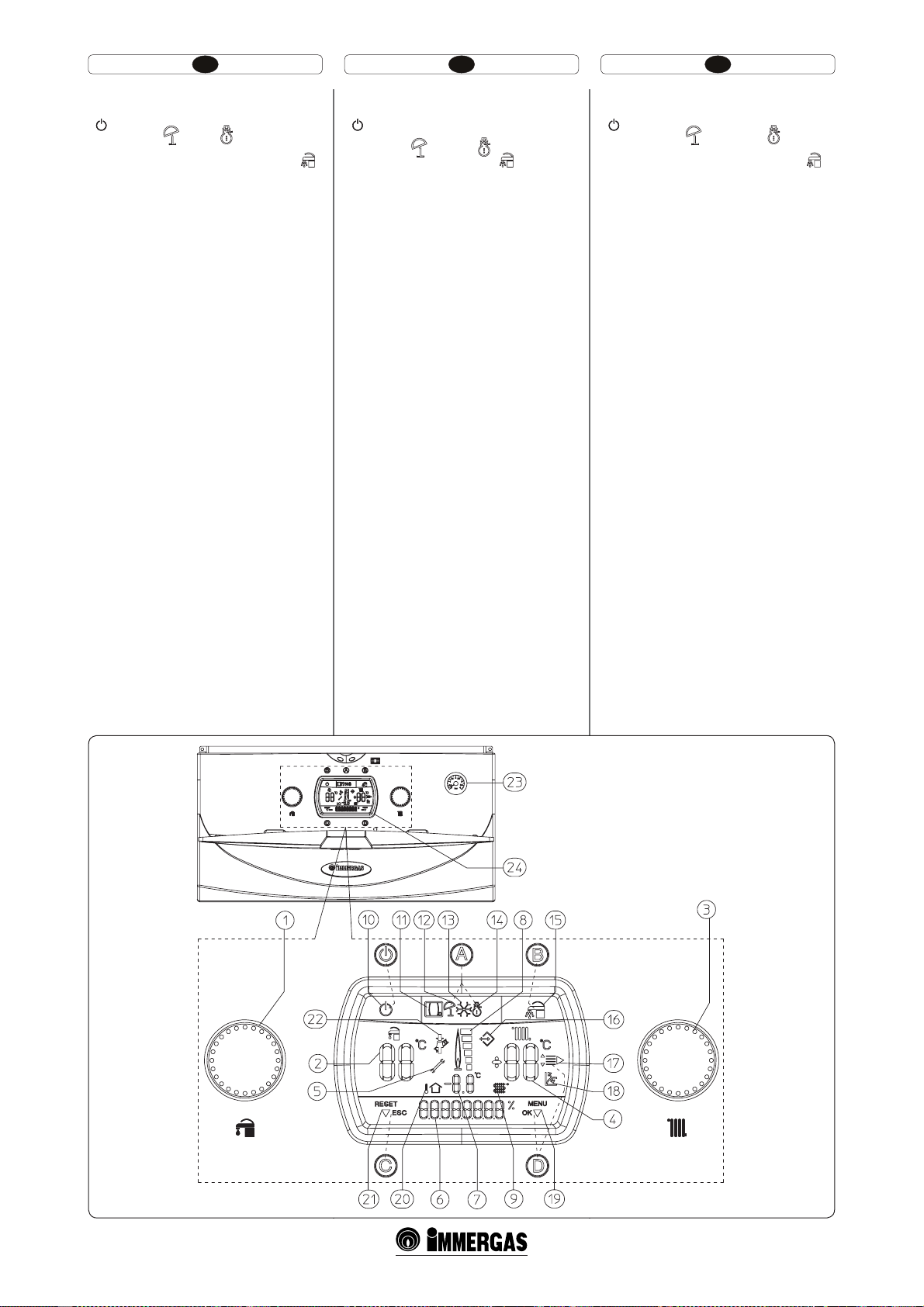
HU IERO
2.3 VEZÉRLŐPANEL.
Jelmagyarázat (2-1 ábra):
- Stand – by – On gomb
A -Nyári ( ) és téli ( ) működtetés
kiválasztó gomb.
B - Használati víz elsőbbséget adó gomb ( )
C - Reset (RESET) / kilépés menüből (ESC)
gomb
D - Belépés a menübe (MENU)/ adatok
megerősítése (OK) gomb
1 - Használati meleg víz hőmérsékletét kivála-
sztó
2 - Használati meleg víz hőmérséklete beállít-
va
3 - Fűtés hőmérséklet kiválasztó
4 - Fűtés hőmérséklet beállítva
5 - Rendellenesség jelenléte
6 - Kazán működési állpotának megjelenítője
8 - Láng jelenléte jel és a rá vonatkozó teljesít-
mény skála
9 e 7 - Elsődleges cserélő kimeneteli víz
hőmérséklet
10 - Kazán stand-by-ban
11 - Kazán távvezérlésre van kapcsolva
(Opcionális)
12 - Működés nyári modalitásban
13 - Fagyásgátló védelem funkció
14 - Működés téli modalitásban
15 - Aktív használati víz elsőbbség
16 - Kapcsolat külső eszközhöz a technikus
számára
17 - Menüadatok megjelenítése
18 - Működés külső hőmérsékleti aktív szon-
dával
19 - Adatmegerősítés vagy belépés a menübe
megjelenítés
20 e 7 - Külső hőmérsékleti aktív szonda
megjelenítője (opcionális)
21 - Reset kérés vagy kilépés a menüből megje-
lenítés
22 - Kéményseprő funkció működik
23 - Kazán manométer
24 - Multifunkcionális display
2.3 PANOU COMENZI.
Legenda (Fig. 2-1):
- Buton Stand-by – On
A - Buton selectare modalitate de funcţionare
vară (
B - Buton prioritate sanitar ( )
C - Buton Reset (RESET) / ieşire meniu (ESC)
D - Buton intrare meniu (MENU)/ conrmare
1 - Selector temperatură apă caldă menajeră
2 - Temperatură apă caldă menajeră setată
3 - Selector temperatură încălzire
4 - Temperatură încălzire setată
5 - Prezenţa anomalie
6 - Vizualizare stare de funcţionare cazan
8 - Simbol prezenţă acără şi scară relativă de
9 e 7 - Temperatură apă ieşire schimbător primar
10 - Centrală în stand-by
11 - Centrală conectată cu comandă de la
12 - Funcţionare in modalitate vară
13 - Funcţiune antigel în curs
14 - Funcţionare in modalitate iarnă
15 - Funcţionare prioritate menajer activă
16 - Racord cu instrumente externe pentru tehnic
17 - Vizualizare rubrici meniu
18 - Funcţionare cu sondă temperatură
19 - Vizualizare conrmare dată sau acces la
20 e 7 - Vizualizare temperatura externă cu
21 - Vizualizare cerere resetare sau ieşire
22 - Funcţiune curăţare coş în curs
23 - Manometru cazan
24 - Display multifuncţiune
) şi iarnă ( )
date (OK)
putere
distanţă (Opţional)
externă activă
meniu
sondă externă legată (opţional)
meniu
2.3 CONTROL PANEL.
Key (Fig. 2-1):
- Stand-by – On Button
A - Summer ( ) and winter ( )functio-
ning mode selection button
B - Domestic hot water priority button (
C - Reset (RESET) / exit menu (ESC) button
D - Menu entry (MENU)/data conrmation
(OK) button
1 - Domestic hot water temperature selector
switch
2 - Domestic hot water temperature set
3 - Heating temperature selector switch
4 - Heating temperature set
5 - Presence of anomalies
6 - Display of boiler functioning status
8 - Flame presence symbol and relative power
scale
9 e 7 - Primary heat exchanger output water
temperature
10 - Boiler in stand-by
11 - Boiler connected to remote control (Optio-
nal)
12 - Functioning in summer mode
13 - Anti/freeze function in progress
14 - Functioning in winter mode
15 - Domestic hot water priority function
active
16 - Connection to external tools for technician
17 - Display of menu items
18 - Functioning with external temperature
probe active
19 - Display of data conrmation or menu
access
20 e 7 - Display of outdoor temperature with
external probe connected (optional)
21 - Display of reset or exit menu request
22 - Chimney sweep function in progress
23 - Boiler manometer
24 - Multi-function display
)
51
2-1
Page 31

HU IERO
2.4 MŰKÖDÉSI ÁLLAPOTOK LEÍRÁSA.
A következőkben a kazán különböző működési
állapotai kerülnek felsorolásra a multifunkcionális
display-en (24) a kijelző (6) által, rövid leírásokkal
a használati kézikönyvben bővebben megmagyarázva.
Display (6) Működési állapot leírása
SUMMER
WINTER
DHW ON
CH ON
CAR OFF
DHWOFF
ERR xx
Nyári működési mód folyamatban levő
kérés nélkül.
Téli működési mód folyamatban levő
kérés nélkül..
Használati víz modalitás folyamatban.
A kazán működik, folyamatban van a
(*)
használati meleg víz melegítése.
Fűtés modalitás folyamatban.
A kazán működik, folyamatban van a
környezeti fűtés.
Fagyásgátló védelem folyamatban.
A kazán működik olymódon, hogy
F3
visszaállítja a kazán befagyása elleni
biztonsági minimális hőmérsékletet.
Távvezérlő (opcionális) ki van kapcsolva.
Érvénytelenített használati víz
elsőbbséggel (15-ös kijelző ki van
kapcsolva), a kazán csak környezeti fűtés modalitásban működik egy
óráig, megtartva azért a használati
víz 20°C-os hőmérsékletét, majd visszatér az előzetesen beállított rendes
működéshez. Super Car alkalmazása
(*)
esetén a korlátozott használati víz
Timer modalitásban való működés
periódusával megegyezően a display-en
megjelenik a DHWOFF kiírás és a 15-ös
és a 2-es kijelzők kikapcsolnak (lásd a
Super CAR kézikönyvét).
Utószellőztetés folyamatban.
A ventilátor a fennmaradó füst kien-
F4
gedésekor az égető kikapcsolása után
működik.
Utókeringetés folyamatban.
Keringető működik az égő kikapcsoló-
F5
dását követően, hogy a primér hálózat
lehűljön.
Távvezérlővel (opcionális) vagy környezeti termosztáttal (TA) (opcionális)
gyújtászár alatt van, a kazán ugyanúgy
P33
működik fűtéskor. (Aktiválható “Perszonalizáció” menüben, lehetővé teszi
a fűtés aktiválását, mégha a Távvezérlő
vagy a TA nem működnek.).
Reset kísérletek befejezve.
Egy órát kell várni az újabb kísérlet
STOP
elvégzéséig.
(Lásd Leállás gyújtás hiányában).
Jelenlevő rendellenesség a rá vonatkozó
hibakóddal.
A kazán nem működik. (lásd Meghibásodások és rendellenességek jelzése
bekezdést).
A használati meleg víz hőmérséklet
kiválasztó elfordítása alatt (1, 2-1 ábra)
megjelenik a folyamatban levő használati víz hőmérsékleti szabályozásának
állapota.
A fűtési hőmérséklet kiválasztó elfordítása alatt (3, 2-1 ábra) megjeleníti
a kazán szállítási hőmérsékletének
szabályozási állapotát a környezeti fűtés
.
számára
SET
Külső szonda jelenlétekor (opcionális)
helyettesíti a kazán szállítási
hőmérsékletének értékét a környezeti
fűtés számára.
Az az érték, amely megjelenik és a szállítási hőmérséklet korrekciója a külső
szonda beállított működési görbéjéhez
képest. Lásd OFFSET a külső szonda
ábráján (1-9 ábra).
2.4 DESCRIERE STĂRI DE
FUNCŢIONARE.
În continuare sunt listate diferitele stări de
funcţionare ale centralei ce apar pe displayul
multifuncţiune (24) prin indicatorul (6) cu o scurtă
descriere pentru care se face trimitere la manualul
de instrucţiuni pentru o explicaţie completă.
Display (6) Descriere stare de funcţionare
SUMMER
WINTER
DHW ON
CH ON
CAR OFF
DHWOFF
STOP
ERR xx
Mod de funcţionare vară fără solicitări
în curs.
Mod de funcţionare iarnă fără solicitări
în curs.
Modalitate menajer în curs.
Centrală în funcţiune, este în curs
(*)
încălzirea apei menajere.
Modalitate încălzire în curs.
Centrală în funcţiune, este în curs
încălzirea ambient.
Modalitatea antigel în curs.
Cazanul în funcţiune pentru a reporni
F3
temperatura minimă de siguranţă
împotriva îngheţării centralei.
Comandă de la distanţă (Opţional)
stins.
Cu prioritatea menajer dezactivată (indicator 15 oprit) centrala funcţionează
în modalitate încălzire ambient timp de
1 oră, menţinând oricum apa menajeră
la temperatura minimă de 20°C, după
care centrala revine la funcţionarea
setată anterior. În caz de utilizare cu
(*)
Super CAR concomitent cu perioada
de funcţionare în modalitate Timer
menajer redus, pe display apare înscrisul DHWOFF iar indicatorii 15 şi
2 se sting (vezi manualul instrucţiuni
Super CAR).
Post ventilare în curs.
Ventilator în funcţie după o stingere a
F4
arzătorului pentru evacuarea gazelor
arse reziduale.
Postcirculare în curs.
Circulator în funcţie după o oprire
F5
a arzătorului pentru a răci circuitul
primar.
Cu comandă de la distanţă (Opţional)
sau termostat ambient (TA) (Opţional)
blocat, centrala funcţionează de
P33
asemenea în încălzire. (Activabilă prin
meniul ”Personalizări” permite activarea
încălzirii chiar dacă comanda la distanţă
sau TA nu sunt în stare de funcţionare).
Tentative de Resetare terminate.
Trebuie aşteptat o oră pentru a recâştiga
1 tentativă.
(Vezi blocare lipsă aprindere).
Anomalie prezenta cu respectivul cod
eroare.
Centrala nu funcţionează (vezi paragraf
semnalare defecţiuni şi anomalii).
În timpul rotirii selectorului temperatura apă caldă menajeră (1 Fig.2-1)
vizualizează starea reglării temperaturii
menajere în curs.
Atunci când se roteşte selectorul,
temperatura de încălzire (3 Fig. 2-1)
vizualizează starea de reglare a temperaturi de retur a centralei pentru încălzirea
mediului..
SET
În prezenţa sondei externe (opţional)
înlocuieşte valoarea de temperatură tur
a centralei pentru încălzirea ambient.
Valoarea ce apare este corectarea
temperaturii de tur faţă de curba de
funcţionare setată de sonda externă.
Vezi OFFSET pe gracul sondei externe
(g. 1-9).
2.4 DESCRIPTION OF FUNCTIONING
STATES.
Below nd a list of boiler functioning states that
appear on the multifunction display (24) by means
of the indicator (6) with a brief description. Refer to
the instruction book for a complete explanation.
Display (6) Description of functioning states
SUMMER
WINTER
DHW ON
CH ON
CAR OFF Remote Control (Optional) o.
DHWOFF
ERR xx
Summer functioning mode in progress
without request.
Winter functioning mode in progress
without request.
Domestic hot water mode in progress.
Boiler functioning, domestic hot water
(*)
heating in progress.
Heating mode in progress.
Boiler functioning, heating in progress.
Anti-freeze mode in progress.
Boiler functioning to restore the mini-
F3
mum safety temperature against boiler
freezing.
With domestic hot water priority disabled (indicator 15 o) the boiler only
functions in heating mode for the duration of 1 hour, however maintaining
the domestic hot water at a minimum
temperature of 20°C, aer which the
boiler goes back tot he normal functioning, which was previously set. If used
(*)
with Super RFC in concomitance of the
functioning period in reduced domestic
hot water Timer mode, DHWOFF will
appear on the display and the indicators
15 and 2 switch off (see Super RFC
instruction book).
Postventilation in progress.
F4
Fan functioning aer burner switch-o
in order to evacuate residual fumes.
Postcirculation in progress.
F5
Pump functioning aer burner switcho in order to cool the primary circuit.
With Remote Control (Optional) or environment thermostat (TA) (Optional)
in block, the boiler functions all the
P33
same in heating mode. (Can be activated
through the “Customisation” menu. It
allows to activate the heating even if the
Remote Control or TA are out of order).
Reset attempts nished.
STOP
Wait for 1 hour to re/acquire 1 attempt.
(See Ignition block).
Anomaly present with relative error
code.
e boiler does not work. (see faults and
anomalies signal paragraph).
During the rotation of the domestic hot
water temperature selector switch (1 Fig.
2-1) view the state of the adjustment of
the domestic hot water temperature in
progress.
During the rotation of the heating
temperature selector switch (3 Fig. 2-1)
it displays the adjustment status of the
boiler delivery temperature for room
SET
heating .
In the presence of external probe (optio-
nal) replace the boiler delivery temperature value to heat the environment.
e value that appears is the correction
of the delivery temperature with respect
to the functioning curve set by the
external probe. See OFFSET on external
probe graphics (Fig. 1-9).
53
Page 32
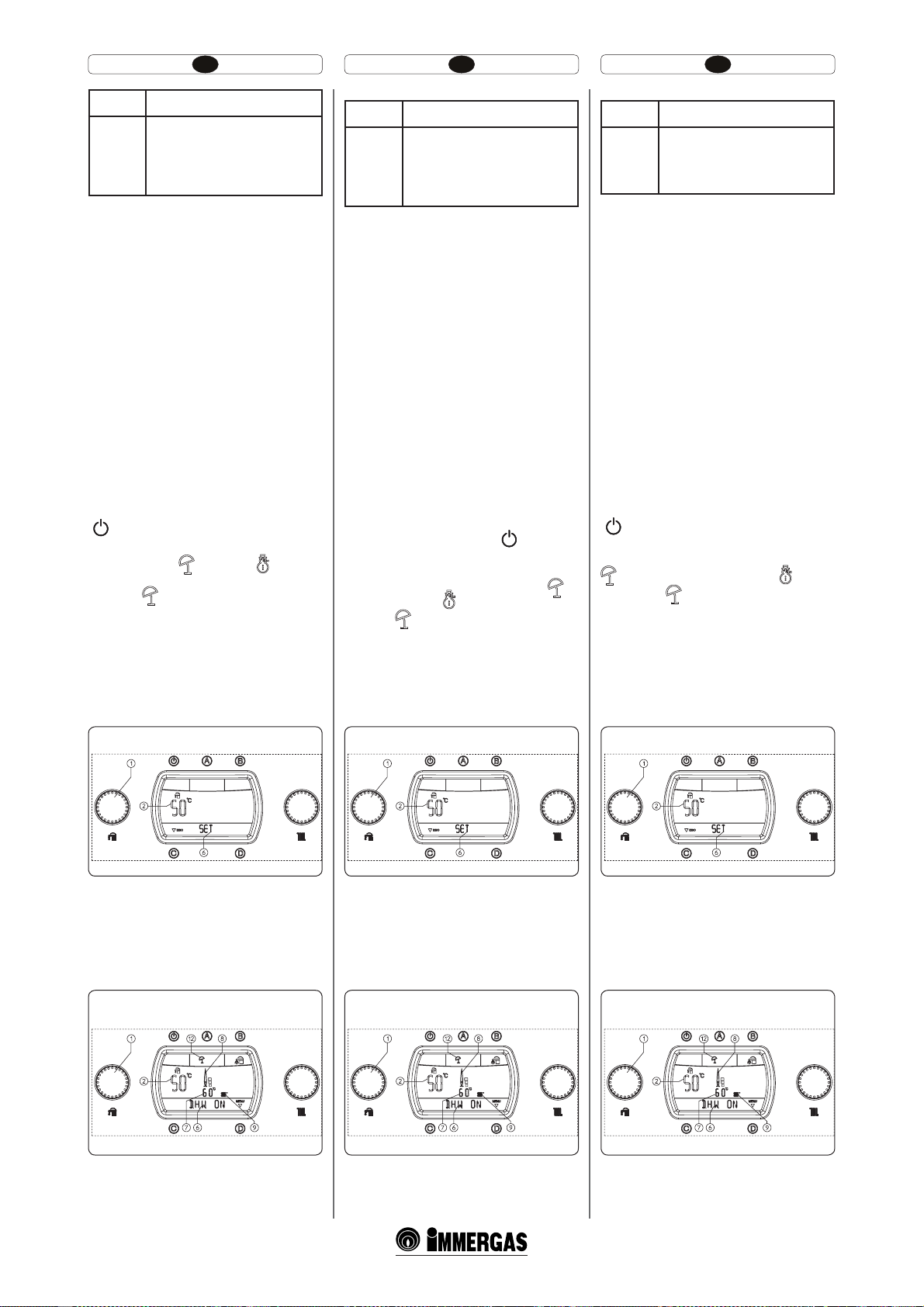
HU IERO
Display (6) Működési állapot leírása
Berendezés szellőztetése folyamatban van.
Ez alatt a fázis alatt, amely 18 óráig
tart, a kazán keringetője be lesz
F8
kapcsolva az előzetesen beállított
időközönként, ilymódon lehetővé válik a
fűtőberendezés szellőztetése.
MEGJ.:
(*) - amikor a kazán külső forraló egységhez
van csatlakoztatva.
2.5 A KAZÁN HASZNÁLATA.
Figyelem: Victrix Superior 32kW X kazán csak
a környezeti fűtésberendezésként volt gyártva,
vagy a specifikus opcionális készletekkel ellátva,
fűtésre és használati meleg víz előállítására. Ezért
a kazán műszerfalán egy, a használati meleg víz
hőmérsékletét szabályozó kapcsoló is található,
de ez csak az opcionális készletekkel működik,
amelyek a használati meleg víz szolgáltatást is
működtetik. Ennek a kapcsolónak és a használati meleg víz szolgáltással kapcsolatos összes
funkció működtetése tilos enélkül az opcionális
specifikus készletek kapcsolódása nélkül.
A bekapcsolás előtt ellenőrizze, hogy a berendezés tele van vizzel, ellenőrizve, hogy a
menométer mutatója (23) 1÷1,2 bar közötti
értéket mutat.
Nyissa ki a kazán tetején levő gázcsapot.
A kikapcsolt kazánnal, a display-en megjelenik
csak a Stand-by jel (10), ennek benyomásával
(
) pedig a kazán bek.
Amint a kazán be van kapcsolva az “A” gomb
többszöri benyomásával megváltozik a működési
mód és a nyári (
módok váltakoznak egymással.
t Nyári (
kitárólag használati meleg víz előállításával
működik, a hőmérsékletet a kiválasztóval
(1) lehet beállítani és az adott hőmérséklet a
display-en (2) jelenítődik meg és megjelenik
a “SET” útmutatás (lásd ábra). A kiválasztó
(1) elfordításával az óramutató járásával
megegyező irányban a hőmérséklet nő, az
óramutató járásával ellenkező irányban pedig
csökken.
) és a téli ( )működési
): ebben a modalitásban a kazán
Display (6) Descriere stare de funcţionare
Eliminare aer din instalaţie în curs.
În timpul acestei faze care durează 18
ore este pusă în funcţiune circulato-
F8
rul centralei la intervale prestabilite,
permiţând astfel eliminarea aerului din
instalaţia de încălzire.
N.B.:
(*) - când centrala este branşată la o unitate
erbător externă.
2.5 UTILIZAREA CENTRALEI.
Atenţie: centrala Victrix Superior 32kW X a fost
proiectată pentru a putea funcţiona ca aparat doar
pentru încălzirea ambientului sau, în combinaţie
cu kituri specice opţionale, pentru încălzirea şi
producerea apei calde menajere. Din acest motiv
bordul centralei este dotat cu un mâner pentru
reglarea temperaturii apei calde menajere dar
funcţionarea sa este activată doar de racordul
kiturilor opţionale care activează şi funcţia de
producere a apei calde menajere. Fără combinarea
acestor kituri specice funcţionarea acestui mâner
şi toate funcţiile privind apa caldă menajeră sunt
oprite.
Înainte de pornire vericaţi ca instalaţia să e plină
de apă, controlând ca săgeata manometrului (23)
să indice o valoare cuprinsă între 1÷1,2 bari.
Deschideţi robinetul din parte superioară a
centralei.
Cu centrala oprită pe display apare doar simbolul
Stand by (10), apăsând butonul (
centrala.
O dată pornită centrala, apăsând repetat butonul
”A” se schimbă modalitatea de funcţionare şi alternativ se trece de la funcţionarea vară (
funcţionarea iarnă (
t Vară (
funcţionează doar pentru încălzirea apei menajere, temperatura este setată prin selectorul
(1) şi respectiva temperatură este vizualizată pe
display (24) prin intermediul indicatorului (2)
şi apare indicaţia “SET” (vezi gura ). Rotind
selectorul (1) în sens orar temperatura creşte şi
antiorar se micşorează.
).
): în această modalitate centrala
) se porneşte
) şi
Display (6) Description of functioning states
System deaeration in progress.
During this phase, which lasts 18
F8
hours, the boiler pump is started at
pre-established intervals, thus allowing
deaeration of the heating system.
N.B.:
(*) - when the boiler is connected to an external
storage unit.
2.5 USE OF THE BOILER.
Important: the Victrix Superior 32kW X boiler
has been designed to function as an appliance
just for heating or, when combined with a specific optional kit, for heating and the production
of domestic hot water. For this reason the boiler
control panel has a knob for the adjustment of
the domestic hot water temperature, but its functioning is only activated by the connection of
the optional kits that also enable the production
of domestic hot water function. Without these
specific kits, the functioning of this knob and
all functions referring to domestic hot water
are inhibited.
Before ignition make sure the heating system is
filled with water and that the manometer (23)
indicates a pressure of÷1,2 bar.
Open the gas cock upstream from the boiler.
With the boiler off, only the stand-by symbol
(10) appears on the display. By pressing the
(
) button the boiler switches on.
Once the boiler is on, by pressing button “A” repeatedly, the functioning mode changes and pass
alternatively from summer functioning mode (
) and winter functioning mode ( ).
t Summer (
ctions only to heat domestic hot water. The
temperature is set using the selector switch
(1) and the relative temperature is shown on
the display (24) by means of the indicator
(2) and the “SET” indication appears (see
figure). By turning the selector switch (1)
in a clockwise direction the temperature
increases and in an anti-clockwise direction
it decreases.
): in this mode the boiler fun-
Használati meleg víz szabályozása
2-2
A használati meleg víz melegítése alatt a
display-en (24) megjelenik a “DHW ON” kiírás
az állapotjelzőn (6) és ezzel egyidőben az égő
begyújtásakor bekapcsol a láng jelenlétét jelző
kijelző (8) a megfelelő teljesítmény skálával és
a kijelző (9 és 7) az elsődleges cserélő azonnali
kimeneteli hőmérsékletével.
Nyári működdteési modalitás használati meleg víz
melegítéssel
2-3
Reglare apă caldă menajeră
2-2
În timpul încălzirii apei calde menajere apare pe
display (24) înscrisul “DHW ON” pe indicatorul
de stare (6) şi simultan cu pornirea arzătorului
se aprinde indicatorul (8) de prezenţă acără
cu respectiva scară de putere şi indicatorul
(9 şi 7) cu temperatura instantanee la ieşirea
schimbătorului primar.
Funcţionare modalitate Vară cu încălzire apă
caldă menajeră
2-3
Adjustment of domestic hot water
2-2
During the heating of the domestic hot water
“DHW ON” appears on the display (24) on
the status indicator (6) and at the same time as
burner ignition the ame presence indicator
switches on (8) with relative power scale and the
indicator (9 and 7) with the instantaneous outlet
temperature from the primary heat exchanger.
Functioning in Summer mode with domestic hot
water heating
2-3
55
Page 33
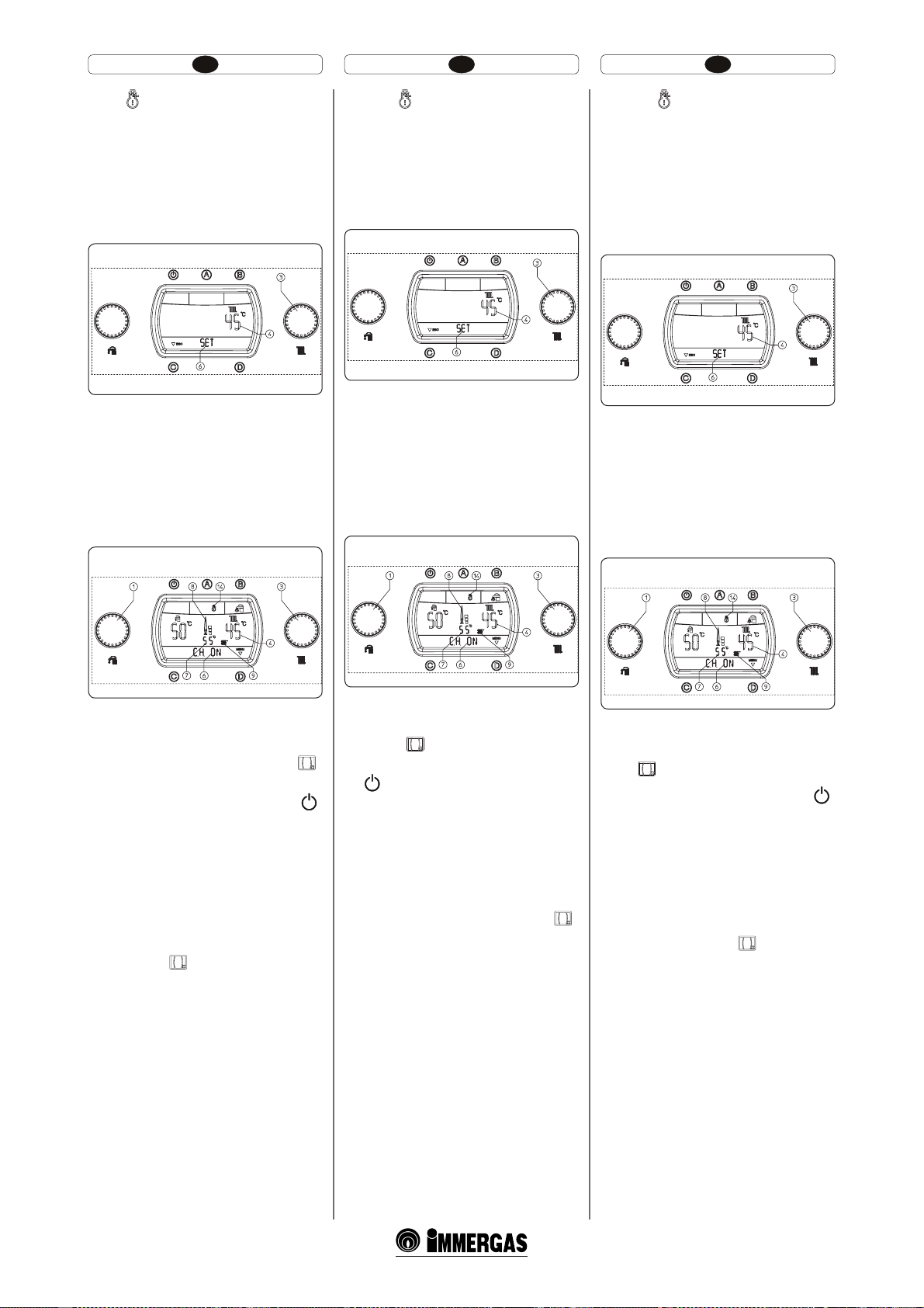
HU IERO
t 5ÏM ): ebben a modalitásban a kazán úgy a
használati meleg víz melegítéssel, mint a környezeti fűtéssel működik. A használati meleg víz
hőmérsékletét mindig az (1) kiválasztó által lehet
szabályozni, a fűtés hőmérsékletét pedig a (3)
kiválasztóval és az erre vonatkozó hőmérséklet
megjelenítődik a display-en (24) a (4) kijelzővel
és megjelenik a “SET” kiírás (lásd az ábrát). A
(3) szelektort elfordítva az óramutató járásával
megegyező irányban a hőmérséklet növelhető,
ezzel ellentétes irányban pedig csökkenthető.
A berendezés szállító hőmérsékletének szabályozása
2-4
A környezeti fűtés kérése alatt a diplay-en (24)
megjelenik a “CH ON” kiírás a (6) állapotkijelzőn
és és ezzel egyidőben az égő begyújtásakor
bekapcsol a láng jelenlétét jelző kijelző (8) a
megfelelő teljesítmény skálával és a kijelző (9
és 7) az elsődleges cserélő azonnali kimeneteli
hőmérsékletével. A fűtés fázisában a kazán amennyiben a berendezésben levő víz hőmérséklete
elegendő a fűtőtestek melegítésére, működhet
csak a kazán kerinegőjének aktiválásával is.
Téli működési mód környezeti fűtéssel
t *BSOʅ ): în această modalitate centrala
funcţionează atât în încălzire apă caldă menajeră
cât şi încălzire ambient. Temperatura apei calde
sanitare se reglează întotdeauna prin selectorul
(1), temperatura de încălzire se reglează prin
selectorul (3) şi respectiva temperatură este
vizualizată pe display (24) prin indicatorul (4)
şi apare indicaţia “SET” (vezi gura). Rotind
selectorul (3) în sens orar temperatura creşte şi
se micşorează invers acelor de ceasornic.
Reglare temperatură de tur instalaţie
2-4
În timpul solicitării de încălzire ambient apare
pe display (24) înscrisul “CH ON” pe indicatorul
de stare (6) şi simultan cu pornirea arzătorului
se porneşte indicatorul (8) de prezenţă acără
cu respectiva scară de putere şi indicatorul
(9 şi 7) cu temperatura instantanee la ieşirea
schimbătorului primar. În faza de încălzire, în
cazul în care temperatura apei din instalaţie este
sucientă pentru a încălzi caloriferele, centrala
poate funcţiona doar cu activarea circulatorului
centralei.
Funcţionare modalitate Iarnă cu încălzire ambient
t 8JOUFS ): in this mode the boiler functions
both for heating domestic hot water and heating the environment. e temperature of the
domestic hot water is always adjusted using the
selector switch (1), the heating temperature is
adjusted using the selector switch (3) and the
relative temperature is shown on the display
(24) using the indicator (4) and the “SET”
indication appears (see gure). By turning the
selector switch (3) in a clockwise direction the
temperature increases and in an anti-clockwise
direction it decreases.
Adjustment of the system delivery temperature
2-4
During the request for room heating “CH ON”
appears on the display (24) on the status indicator (6) and at the same time as burner ignition
the ame presence indicator switches on (8) with
relative power scale and the indicator (9 and 7)
with the instantaneous outlet temperature from
the primary heat exchanger. In the heating phase,
if the temperature of the water contained in the
plant is sucient to heat the radiators, the boiler
can only function with the activation of the boiler
pump.
Winter mode functioning with room heating
2-5
t Működés a Remote-barát vezérlővel (CAR)
(Opcionális). A CAR-hoz való csatlakoztatás
esetében a kazán automatikusan beindítja a
berendezést és a display-en megjelenik a (
jel. Ettől a pillanattól fogva az összes vezérlés és
szabályozás a CAR számára vannak átadva, a
kazánon még marad a Stand-by funkció “
a Reset “C” gomb, a “D” belépés a menübe gomb
és a “B” használati víz elsőbbség gomb.
Figyelem: amennyiben a kazánt Stand-by-ba
teszik (10) a CAR-on megjelenik a hibás kapcsolat hibakód “CON”, a CAR mindazonáltal
ellátás alatt marad anélkül, hogy a memorizált
programok elvesznének.
t Működés a Super Remote-barát vezérlővel
(Super CAR) (Opcionális). A Super CAR-hoz
való csatlakoztatás esetében a kazán automatikusan beindítja a berendezést és a display-en
megjelenik a (
kezelni lehet a szabályozásokat a Super CARról vagy a kazánon. Kivéve a környezeti fűtés
hőmérsékletét, amely a display-en jelenik meg,
de a Super CAR vezényli.
Figyelem: amennyiben a kazánt Stand-by-ba
teszik (10) a Super CAR-on megjelenik a hibás
kapcsolat hibakód “ERR>CM” , a Super CAR
mindazonáltal ellátás alatt marad anélkül, hogy
a memorizált programok elvesznének.
t Használati víz elsőbbség funkció. A “B” gomb
lenyomásával érvényteleníteni lehet a használati
víz elsőbbséget, amelyet a (15) jel a (24) displayen jelez. Az érvénytelenített funkció 20°C-os
hőmérsékleten tartja a forraló vizét egy órán
keresztül, elsőbbséget adva a környezeti fűtés
funkciónak.
t Működés külső szondával (18. rész),
opcionális. A külső opcionális szondával
).jel. Ettől a pillanattól fogva
).
t Funcţionare cu Comandă de la distanţă (CAR)
(Opţional). În caz de racord la CAR centrala
indică automat dispozitivul şi pe display apare
simbolul ( ). Din acest moment toate comenzile şi reglările sunt trimise la CAR; pe centrală
rămân oricum în funcţiune butonul Standy By
“
”, butonul Reset ”C”, butonul intrare meniu
”D” şi butonul prioritate menajer ”B”.
”,
Atenţie: Dacă centrala se pune în stand by (10)
pe CAR va apărea simbolul eroare conexiune
”CON”, iar CAR-ul este oricum menţinut
alimentat fără a pierde astfel programele memorate.
t Funcţionare cu Super Comando Amico
Remoto (Super CAR) (Opţional). În caz de
racord la Super CAR centrala indică automat
dispozitivul şi pe display apare simbolul (
Din acest moment se pot opera reglări indiferent
de la Super CAR sau de la centrală. În afară
de temperatura de încălzire ambient care este
vizualizată pe display dar gestionată de Super
CAR.
Atenţie: Dacă se poziţionează centrala în stand
by (10) pe Super CAR va apărea simbolul de
eroare conexiune “ERR>CM”, Super CAR-ul
este oricum menţinut alimentat fără a pierde
astfel programele memorate.
t Funcţie prioritate menajer. Apăsând butonul
“B” se dezactivează funcţia prioritate menajer
care e semnalată de stingerea pe display (24) a
simbolului (15). Funcţia dezactivată menţine
apa din erbător la temperatura de 20°C timp
de o oră, dând prioritate de funcţionare încălzirii
ambientului.
t Funcţionare cu sondă externă (part.18)
opţional. În caz de instalaţie cu sonda externă
opţional temperaturi de tur a centralei pentru
încălzirea ambientului este gestionată de sonda externă măsurată în funcţie de temperatura
2-5
t Operation with Remote Friend Control (RFC)
(Optional). In the case of connection to the RFC,
the boiler automatically detects the display and
the ( ). symbol appears on the display. From
this moment all controls and adjustments are
referred to the RFC. e stand-by button “
the reset button “C”, the menu entry button “D”
and the domestic hot water priority button “B”
however remain active.
Important: if the boiler is put into stand-by (10)
the “CON” connection error symbol will appear
on the RFC. e RFC is however powered constantly so as not to loose memorised programs.
t Operation with Super Remote Friend Control
(Super RFC) (Optional). In the case of connec-
).
tion to the Super RFC, the boiler automatically
detects the display and the (
on the dis pla y. F rom thi s mo ment it i s p oss ibl e to
make adjustments indierently from the Super
RFC or the boiler. Except for the room heating
temperature that is shown on the display but
managed by the Super RFC.
Important: If the boiler is put into stand-by
(10) the “ERR>CM” connection error symbol
will appear on the Super RFC. e Super RFC
is however powered constantly so as not to loose
memorised programs.
t Domestic hot water priority function. By pres-
sing button “B” the domestic hot water priority
function is deactivated, which is marked by the
switch-o of the symbol (15) on the display (24).
e disabled function keeps the water contained
in the storage tank at a temperature of 20°C for
1 hour, giving the functioning priority to room
heating.
t Functioning with external probe (part. 18)
optional. In the case of a system with optional
). symbol appears
2-5
”,
57
Page 34
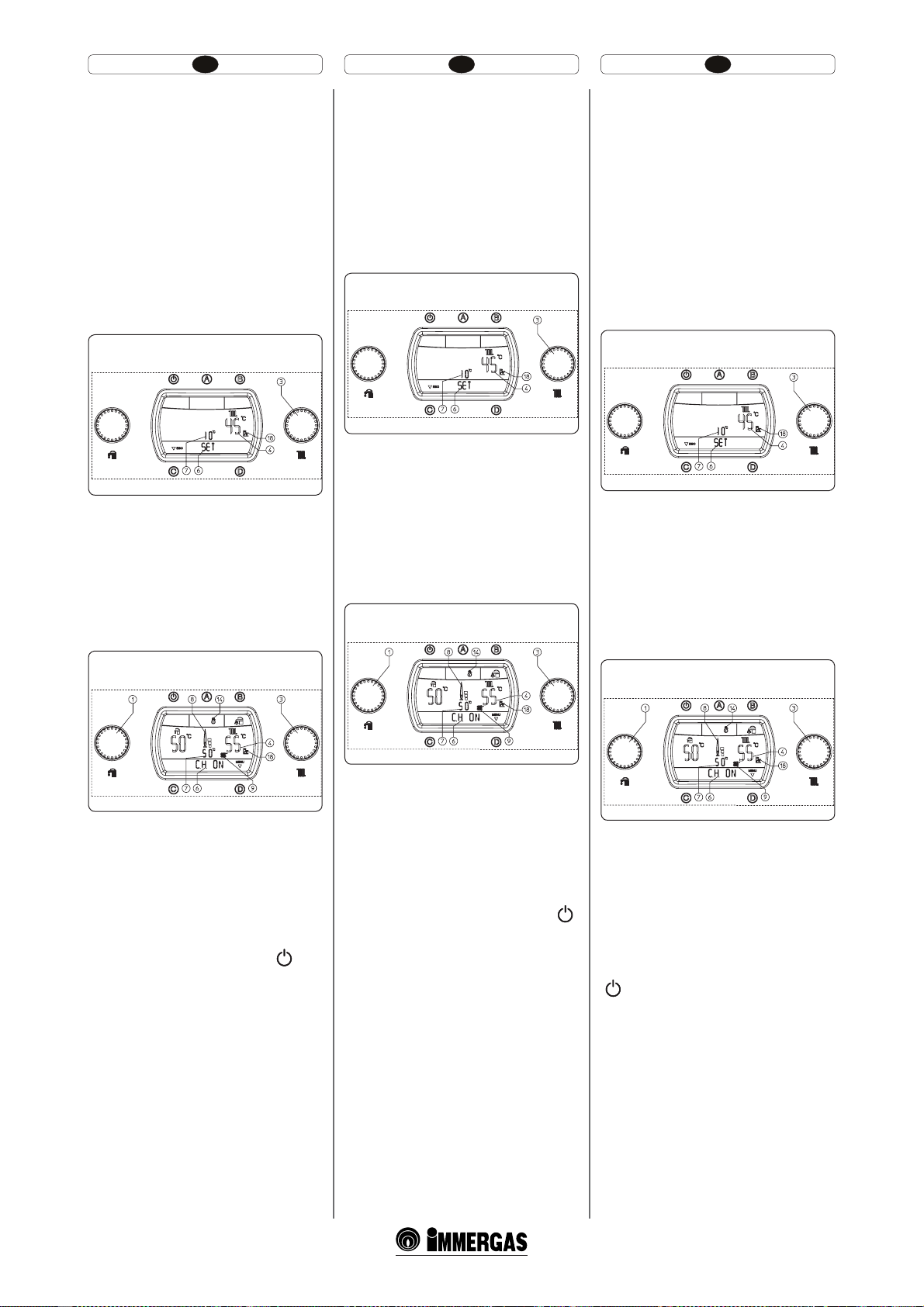
HU IERO
rendelkező berendezés esetében a kazán
szállítási hőmérsékletét a külső szonda kezeli
a mért külső hőmérséklet függvényében (1.6
belezd. és 3.8 bekezd. a “P66”-ban). A szállítási
hőmérsékletet -15°C -től +15°C-ig lehet szabályozni a szabályozó görbe függvényében (lásd
grakon, 1-9 ábr., Oset érték). Ez a pontosítás,
aktiválható a (3) kiválasztóval, mindig azonos
marad bármely külső hőmérséklet esetében,
az oset hőmérséklet megváltozatását a (7),
kijelző jeleníti meg, a (4) kijelző pedig az
aktuális szállítási hőmérsékletet jeleníti meg, és
néhány percre a módosítást követően, fel lesz
frissítve, és a display-en megjelenik a “SET”
útmutatás (lásd ábra). A (3) szelektort elfordítva
az óramutató járásával megegyező irányban a
hőmérséklet növelhető, ezzel ellentétes irányban pedig csökkenthető.
A berendezés szállítási hőmérsékletének szabál-
yozása külső szondával (opcionális)
2-6
A környezeti fűtés kérése alatt a diplay-en (24)
megjelenik a “CH ON” kiírás a (6) állapotkijelzőn
és és ezzel egyidőben az égő begyújtásakor
bekapcsol a láng jelenlétét jelző kijelző (8) a
megfelelő teljesítmény skálával és a kijelző (9
és 7) az elsődleges cserélő azonnali kimeneteli
hőmérsékletével. A fűtés fázisában a kazán amennyiben a berendezésben levő víz hőmérséklete
elegendő a fűtőtestek melegítésére, működhet
csak a kazán kerinegőjének aktiválásával is.
externă măsurată. (Parag.1.6 şi parag. 3.8 la
rubrica “P66”). Se poate modifica temperatura
de tur de la -15°C la +15°C faţă de curba de
reglare (vezi grafic fig. 1-9 valoare Offset).
Această corectare, efectuabilă cu selectorul
(3) se menţine activă pentru orice temperatură
externă măsurată, modificarea temperaturii
offset este vizualizată prin indicatorul (7), iar
pe indicatorul (4) este vizualizată temperatura
de tur actuală şi după câteva secunde de la
modificare este actualizată cu noua corectură,
pe display apare indicaţia “SET” (vezi figura).
Rotind selectorul (3) în sens orar temperatura
creşte şi antiorar temperatura scade.
Reglarea temperaturii de tur instalaţie cu sondă
În timpul cererii de încălzire ambient apare pe
display (24) înscrisul ” CH ON” pe indicatorul
de stare (6) şi simultan cu pornirea arzătorului
se aprinde indicatorul (8) de prezenta acără
cu respectiva scară de putere şi indicatorul (9
şi 7) cu temperatura instantanee la ieşire din
schimbătorul primar. În faza de încălzire, în
cazul în care de temperatura a apei din instalaţie
este suficientă pentru a încălzi caloriferele,
centrala poate funcţiona doar cu activarea circulatorului centralei.
Funcţionare modalitate iarnă cu sondă externă
externă (opţional)
2-6
(opţional)
external probe, the boiler delivery temperature
for room heating is managed by the external
probe depending on the external temperature
measured (Par. 1.6 and par. 3.8 under “P66”).
It is possible to modify the delivery temperature from -15°C to +15°C with respect to the
adjustment curve (see graphics g. 1-9 Oset
value). is correction, which can be activated
using selector switch (3) is kept active for any
external temperature measured. e modication of the oset temperature is displayed using
the indicator (7). e indicator (4) shows the
current delivery temperature and aer a few
seconds from the modication it is updated
with the new correction. e “SET” indication
appears on the display (see gure). By turning
the selector switch (3) in a clockwise direction
the temperature increases and in an anticlockwise direction it decreases.
Delivery temperature adjustment of system with
During the request for room heating “CH ON”
appears on the display (24) on the status indicator (6) and at the same time as burner ignition
the ame presence indicator switches on (8) with
relative power scale and the indicator (9 and 7)
with the instantaneous outlet temperature from
the primary heat exchanger. In the heating phase,
if the temperature of the water contained in the
plant is sucient to heat the radiators, the boiler
can only function with the activation of the boiler
pump.
external system (optional)
2-6
Működés téli modalitásban külső szondával
Innentől fogva a kazán automatikusan működik.
Hőkérés hiányában, a kazán “felfüggesztett”-en
működik, a lángőr hiányában működő kazánhoz
hasonlóan.
MEGJ.: lehetséges, hogy kazán bekapcsol automatikusan, amennyiben a fagyásgátló védelem
be van kapcsolva (13). Ugyanakkor a kazán rövid
ideig működhet használati víz felvétele után, hogy
használati vízhálózatot felmelegítse.
Figyelem: A stand-by modalitásban (
kazánnal nem lehet meleg vizet előállítani és
nem garantáltak a következő biztonsági funkciók:
szivattyú, fagyásgátló és háromirányú letapadás
elleni védelem.
(opcionális)
2-7
) levő
2-7
Din acest moment centrala funcţionează automat.
În absenţa solicitărilor de căldură, centrala trece
în funcţie de ”aşteptare” echivalentă cu centrala
alimentată fără prezenţa ăcării.
N.B.: E posibil ca centrala să se pună în funcţiune
automat în cazul în care se activează funcţiunea
antigel (13). În plus centrala poate rămâne în funcţie
pentru o perioadă de timp scurtă după preluarea de
apă caldă menajeră pentru a readuce în temperatură
circuitul sanitar.
Atenţie:cu centrala în modalitate stand by (
nu se poate produce apă caldă şi nu sunt garantate
funcţiile de siguranţă: antiblocare pompă, antigel
şi antiblocare trei căi.
Functioning in winter mode with external probe
From this moment the boiler functions automatically. With no demand for heat, the boiler goes to
“standby” function, equivalent to the boiler being
powered without presence of ame.
N.B.: e boiler may start-up automatically if the
anti-freeze function is activated. (13). Moreover,
)
the boiler can function for a brief period of time
aer a withdrawal of domestic hot water in order
to take the domestic hot water temperature back
into temperature.
Attention: with the boiler in stand-by mode
) hot water cannot be produced and the safety
(
systems cannot be guaranteed, such as: pump antiblock, anti-freeze and three way anti-block.
(optional)
2-7
59
Page 35
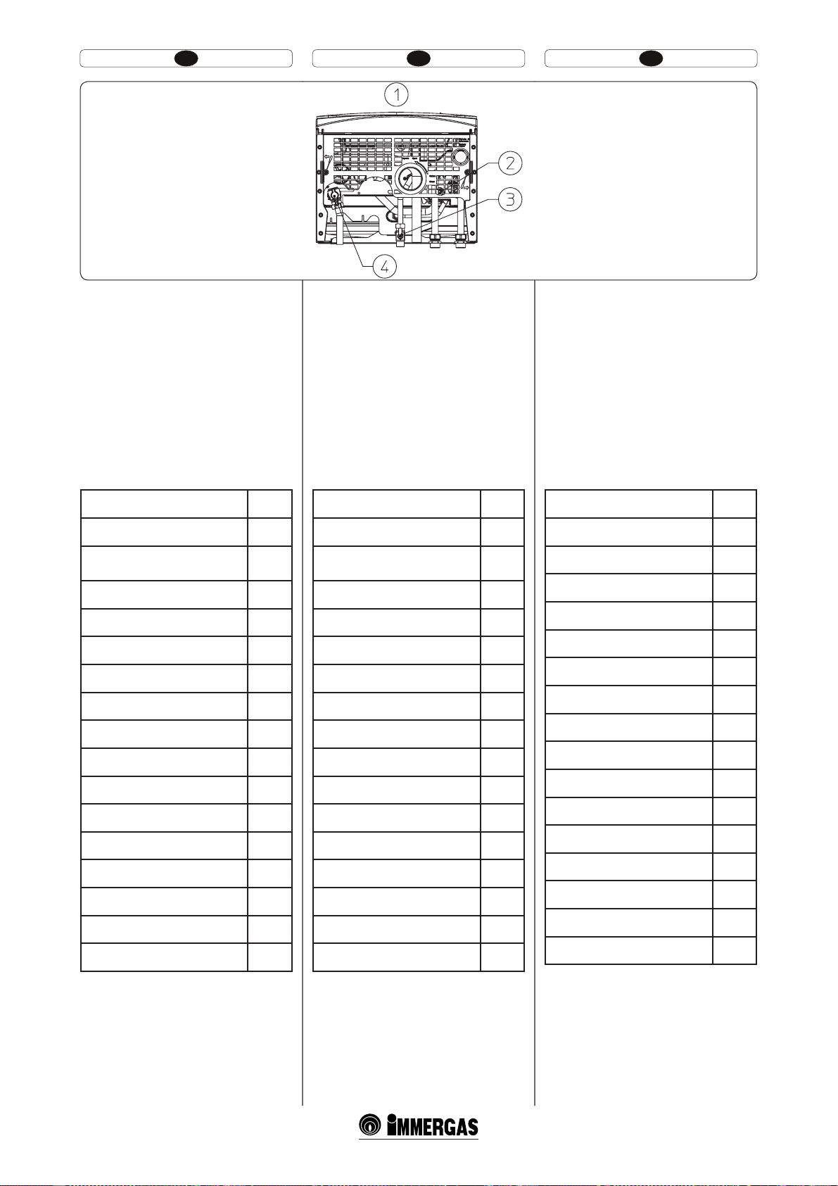
HU IERO
2-8
Jelmagyarázat (2-8 ábra):
1 - ALSÓ RÁLÁTÁS
2 - A berendezés újrafeltöltő csapja
3 - Berendezést víztelenítő csap
4 - hazsnálati víz bemeneteli csapja
2.6 MEGHIBÁSODÁSOK ÉS RENDELLE
NESSÉGEK JELZÉSE.
Az Victrix Superior kW kazán az esetenkénti
rendellenességet jelez az (5) jelkép villogása által,
amelyhez az “ERRxx” kijelzés társul a (6) kiválasztón, ahol “xx” a következő táblázatban látható
hibakódnak felel meg. Az esetenkénti vezérlőn a
hibakód ugyanazon számkód által jelenítődik meg,
amelyet a következő példa ábrázol (pl. . CAR = Exx,
Super CAR = ERR>xx).
Jelzett rendellenesség Hibakód
Gyújtás hiányának blokkolása 01
Biztonsági termosztát blokkolása
(túlmelegedés), lángellenőrző rendellenesség
Füstcső leállása 03
Kapcsolatok ellenállásának leállása 04
Szállító szonda rendellenessége 05
Elégtelen nyomás a berendezésben 10
Bojler szonda rendellenessége 12
Kongurációs hiba 15
Ventilátor rendellenesség 16
Lángőr leállása 20
Visszacsatlakozási szonda rendellenesség
Gombrendszer rendellenesség 24
Elégtelen körforgás 27
Távvezérlés jel vesztessége 31
Alacsony ellátási feszültség 37
Tűzjel vesztessége 38
02
23
Legenda (Fig. 2-8):
1 - VEDERE INFERIOARĂ
2 - Robinet umplere instalaţie
3 - Robinet golire instalaţie
4 - Robinet intrare apă menajeră
2.6 SEMNALĂRI DEFECŢIUNI ŞI ANOMA
LII.
Centrala Victrix Superior kW semnalează o
eventuală anomalie prin intermediul pâlpâirii
simbolului (5) împreună cu indicaţia ”ERRxx” pe
indicatorul (6) unde ”xx” corespunde codului eroare
descris în tabelul următor. Pe eventuala comandă de
la distanţă codul eroare va vizualizat prin acelaşi
cod numeric reprezentat după următorul exemplu
(ex. CAR= Exx, Super CAR = ERR>xx).
Anomalie semnalată
Blocare nepornire 01
Blocare termostat siguranţă
(supratemperatură), anomalie control
acără
Blocare termostat gaze arse 03
Blocare rezistenţă contacte 04
Anomalie sondă trimitere 05
Presiune instalaţie insucientă 10
Anomalie sondă boiler 12
Eroare conguraţie 15
Anomalie ventilator 16
Blocare acără parazită 20
Anomalie sondă retur 23
Anomalie tablou comandă 24
Circulaţie insucientă 27
Pierdere comunicare Comandă de la
distanţă
Tensiune de alimentare joasă 37
Pierdere semnal de acără 38
Cod
eroare
02
31
Key (Fig. 2-8):
1 - LOWER VIEW
2 - System lling valve
3 - System draining valve
4 - Domestic hot water inlet valve
2.6 FAULT AND ANOMALY SIGNALS.
e Victrix Superior kW boiler signals any anomalies by the ashing symbol (5) along with the
“ERRxx” indication on the indicator (6) where
“xx” corresponds to the error code described in
the following table. On the eventual remote control the error code will be displayed by means of
the same numerical code represented according
to the following example (e.g. RFC = Exx, Super
RFC = ERR>xx).
Anomaly signalled
Ignition block 01
Safety thermostat block (over-temperature), ame control anomaly
Fumes thermostat block 03
Contacts resistance block 04
Delivery probe anomaly 05
Insucient system pressure 10
Storage tank probe anomaly 12
Conguration error 15
Fan anomaly 16
Parasite ame block 20
Return probe anomaly 23
Push button control panel anomaly 24
Insucient circulation 27
Loss of remote control communication
Low power supply voltage 37
Loss of ame signal 38
Error
code
02
31
Leblokkolás gyújtás hiányában. A környezet
fűtésének vagy az egészségügyi meleg víz szolgáltatás kérésekor a kazán mindig automatikusan
bekapcsol. Ha 10 másodperc alatt az égető nem
gyúl be, a kazán működése 30 másodpercig fel van
függesztve, újra kell próbálkozni, és másodszori
próbálkozásra sem gyúl be, a kazán “leblokkol
gyújtás hiányában” (ERR01). A „Leblokkolás
gyújtás hiányában” megszüntetése érdekében a
Reset “C”gombot kell benyomni. A rendellenes-
Blocare nepornire. Când se cere încălzirea mediului ambient sau producerea de apă caldă menajeră,
centrala se aprinde automat. Dacă într-un interval
de 10 secunde nu are loc aprinderea arzătorului,
centrala va rămâne în aşteptare pentru 30 secunde,
reîncearcă, şi dacă eşuează şi în a doua încercare,
intră în “blocare din cauza nepornirii” (ERR01).
Pentru a elimina “ blocarea din cauza nepornirii”
este necesar să apăsaţi butonul Reset ”C”. Este
posibilă resetarea anomaliei de 5 ori consecutiv,
61
Ignition block. e boiler ignites automatically
with each demand for room heating or hot water
production. If this does not occur within 10 seconds, the boiler remains in stand-by for 30 seconds, try
again and if the second attempt fails it will go into
“ignition block” (ERR01). To eliminate “ignition
block” the Reset button “C” must be pressed. e
Anomaly can be reset 5 times consecutively, aer
which the function in inhibited for at least one hour.
One attempt is gained every hour for a maximum
of 5 attempts. By switching the appliance on and o
Page 36

HU IERO
séget 5-ször egymás után lehet reset-álni, azután
a működtetés nem lehetséges legelább egy óráig és
maximum 5-ször lehet próbálkozni minden órában.
Az első begyújtáskor vagy a berendezés hosszabb
ideig való leállása után szügséges lehet a „Leblokkolás gyújtás hiányában” kizárását elvégezni. Ha
a jelenség gyakran előfordul, hívjon szakképzett
technikust (pl. Immergas Technikai asszisztencia
szolgáltatója).
Biztonsági termosztát leállása (túlmelegedés
miatt). Ha a rendes működés alatt rendellenesség
miatt fokozott belső túlmelegedés, vagy a láng
szabályozójának rendellenessége merül fel, a kazán
túlmelegedési lebblokkálódásba kerül (ERR02).
A „Leblokkolás túlmelegedés miatt”állapotának
megszüntetése érdekében a Reset C gombját
kell benyomni. Ha a jelenség gyakran előfordul,
szakképzett technikust kell hívni (pl. Immergas
Technikai asszisztencia szolgáltatója).
Füst nyomásmérő rendellenessége . Akkor
jelentkezik, ha a kondenzációs modul belső
(mészkőlerakódás, vagy sár miatt) vagy külső
(égéstermékek miatt) csövei részlegesen el vannak
záródva. A kazán normál feltételeinek visszaállításakor a kazán újra elindul a Reset “C” benyomásával;
és hívjon szakképzett technikust (pl. Immergas
Technikai asszisztencia szolgáltatója) az eldugulások szabaddá tétele végett.
Kontaktusok ellenállásának blokkolása. A
biztonsági termosztát meghibásodásakor merül ez
fel (túlmelegedés) vagy a lángelleneőrző rendellenességének esetében. Ha a kazán nem kapcsol be,
szakképzett technikust kell hívni (pl. Immergas
Technikai asszisztencia szolgáltatója).
Szállító szonda rendellenessége. Ha a séma a
berendezés NTC szállító szondájának rendellenességét mutatja, a kazán nem működik; és szakképzett
technikust kell hívni (pl. Immergas Technikai
asszisztencia szolgáltatója).
Melegítő szonda meghibásodása (opcionális). Ha
a rendellenességre vonatkozó rajz a kazán melegítő
szondáján rendelleneséget, a kazán jelzi a rendellenességet. Ebben az esetben a kazán továbbra is
előállítja a meleg vizet, de nem a legmegfelelőbb
módon. Ugyanakkor ebben az estben a fagyásgátló
sem működik, és szakképzett technikust kell hívni
(például, Immergas Szervízszolgálata).
Elégtelen nyomás a berendezésben. Nincs
elegendő nyomása a viznek a fűtési hálózatban,
amely biztosítaná a kazán rendes működését.
Ellenőrizze, a kazán manométerén (1), hogy a berendezésben levő nyomás1÷1,2 bar között van, és
esetleg állítsa vissza a megfelelő nyomást.
Bojler szonda rendellenessége. Amennyiben a
kártya rendellenességet észlel a bojler szondán
(12-es kód), a kazán nem képes tovább meleg
vizet előállítani. Egy felhatalmazott szakembert
kell hívni (például, Immergas Műszaki Szervízszolgáltatását).
Kongurációs hiba. Amennyiben a kártya rendellenességet vagy az elektromos kábelek inkongruenciáját jelzi, a kazán nem kapcsol be. A kazánt nem
kell újra reset-álni lehet egy új bekapcsolási kísérletkor. Ha a jelenség g yakran előfordul, szakképzett
technikust kell hívni (pl. Immergas Technikai
asszisztencia szolgáltatója).
Ventilátor rendellenessége. Amennyiben a
ventilátor mechanikus vagy elektronikus meghibásodást jelez. A “ventilátor rendellenesség”-ének
kizárása végett nyomja be a “C” Reset gombot. Ha
a jelenség gyakran előfordul, szakképzett technikust
kell hívni (pl. Immergas Technikai asszisztencia
szolgáltatója).
Parazita láng leállása. A keringetési hálózat
vesztességekor vagy a lángelleneőrző rendellenes
működésekor merül ez fel. A kazán nem indul
el. A kazánt újra reset-álni lehet egy új bekapcsolási kísérletkor. Ha a jelenség gyakran előfordul,
szakképzett technikust kell hívni (pl. Immergas
Technikai asszisztencia szolgáltatója).
Visszacsatlakozási szonda rendellenessége. Ebben
az esetben a keringető nem ellenőriz a megfelelő
módon, amennyiben mint “AUTO” van beállítva.
A kazán működik, de a rendellenesség megszüntetése végett szakképzett technikust kell hívni (pl.
după care funcţiunea este interzisă pentru cel
puţin o oră, ind posibilă o singură încercare pe
oră cu maxim cinci tentative. Oprind şi repornind
aparatul, se recâştigă cele cinci tentative. La prima
aprindere sau după o perioadă lungă de inactivitate
a aparatului poate nevoie să se intervină pentru
eliminarea “ blocării din cauza nepornirii”. Dacă
fenomenul se produce frecvent, chemaţi un tehnician autorizat (de exemplu Serviciul de Asistenţă
Tehnică Immergas).
Blocare termostat de siguranţă (supraîncălzire).
În timpul funcţionării normale, dacă din cauza
unei anomalii se produce o supraîncălzire internă
excesivă, sau din cauza unei anomalii la secţiunea
control acără centrala va intra în “blocare din
cauza supraîncălzirii” (ERR02). Pentru a elimina
‘blocarea din cauza supraîncălzirii’ e necesar să
apăsaţi butonul Reset ”C”. Dacă fenomenul se
produce frecvent, chemaţi un tehnician autorizat (de exemplu Serviciul de Asistenţă Tehnică
Immergas).
Blocare termostat gaze arse. Se produce în caz
de blocare parţială internă (datorată prezenţei
calcarului şi noroiului) sau externă (reziduuri de
combustie) în modului de condensare. Pentru a
elimina ”blocarea termostat fumuri” este necesar să
apăsaţi butonul Reset ”C”; e necesar să chemaţi un
tehnician abilitat pentru a îndepărta obstrucţiile (de
ex. Serviciul de Asistenţă Tehnică Immergas).
Blocare rezistenţă contacte. Se produce în cazul
defectării termostatului de siguranţă (supraîncălzire)
sau anomalie în controlarea ăcării. Centrala nu
intră în funcţiune; este necesar să chemaţi un tehnician autorizat (de exemplu Serviciul de Asistenţă
Tehnică Immergas).
Defecţiune sondă tur. Dacă, placa electronică
detectează o anomalie pe sonda NTC tur instalaţie,
centrala nu intră în funcţiune; este necesar să
chemaţi un tehnician autorizat (de exemplu Serviciul de Asistenţă Tehnică Immergas).
Defecţiune sondă menajer. Dacă placa indică
o anomalie pe sonda NTC menajer cazanul
semnalează o anomalie. În acest caz centrala
continuă să producă apă caldă menajeră dar
cu prestaţii inferioare. În plus, în acest caz este
inhibată funcţia antigel şi este necesar să chemaţi
un tehnician abilitat (de exemplu Serviciul Asistenţă
Tehnică Immergas).
Presiune instalaţie insucientă. Nu este relevată o
presiune a apei în interiorul circuitului de încălzire
sucientă pentru a garanta funcţionarea corectă a
centralei. Vericaţi pe manometrul centralei (1) ca
presiunea instalaţiei să e cuprinsă între 1÷1,2 bari
şi eventual restabiliţi presiunea corectă.
Anomalie sondă boiler. Dacă placa relevă o anomalie pe sonda boiler (cod 12) centrala nu mai
poate produce apă caldă menajeră. Este necesar să
chemaţi un tehnician abilitat (de exemplu Serviciul
de Asistenţă Tehnică Immergas).
Eroare conguraţie. Dacă placa relevă o anomalie
sau o neconcordanţă pe cablajul electric centrala nu
porneşte. În caz de revenire la condiţiile normale
centrala reporneşte fără nevoia de a resetată.
Dacă anomalia persistă este necesar să chemaţi un
tehnician abilitat (de exemplu) Serviciul Asistenţă
Tehnică Immergas).
Anomalie ventilator. Se produce în cazul în care
ventilatorul prezintă o defecţiune mecanică sau
electrică. Pentru a elimina ”anomalia ventilator”
este necesar să apăsaţi butonul Reset ”C”. Dacă
anomalia persistă este necesar să chemaţi un
tehnician abilitat (de exemplu Serviciul Asistenţă
Tehnică Immergas).
Blocare flacără parazită. Se produce în cazul
dispersiei circuitului de indicare sau anomalie în
controlarea ăcării. Este posibilă resetarea centralei pentru a permite o nouă tentativă de pornire.
Dacă centrala nu intră în funcţiune este necesar
să chemaţi un tehnician autorizat (de exemplu
Serviciul de Asistenţă Tehnică Immergas.
Anomalie sondă retur. în această condiţie centrala
nu controlează circulatorul corect dacă e setat
ca “AUTO”.Centrala continuă să funcţioneze dar
pentru a elimina anomalia este necesar să chemaţi
un tehnician abilitat (de exemplu Serviciul Asistenţă
the 5 attempts are re-acquired. On commissioning
or aer extended inactivity it may be necessary to
eliminate the “ignition block”. If this phenomenon
occurs frequently, contact a qualied technician for
assistance (e.g. Immergas Aer-sales Service).
Safety thermostat block (over-temperature).
During operation, if a fault causes excessive
overheating internally, or an anomaly occurs in the
ame control section, an over-temperature block
is triggered in the boiler (ERR02). To eliminate
“over-temperature block” the Reset button “C” must
be pressed. If this phenomenon occurs frequently,
contact a qualied technician for assistance (e.g.
Immergas Aer-sales Service).
Fumes thermostat block is occurs in the case
of partial internal obstruction (due to the presence
of lime scale or mud) or external blocking should
occur (combustion residues) to the condensation
module. To eliminate the “fumes thermostat block”
the Reset button “C” must be pressed. Call an
authorised technician to remove the obstructions
(e.g. Immergas Aer-sales Service).
Contacts resistance block. is occurs in the case
of faults to the safety thermostat (over-temperature)
or anomaly in the ame control. e boiler does not
start and a technician must be called (e.g. Immergas
Aer-Sales Service).
Delivery probe anomaly. If the board detects an
anomaly on the system NTC delivery probe, the
boiler will not start; contact a qualied technician
for assistance (e.g. Immergas Aer-Sales Service).
Delivery probe anomaly. If the board detects an
anomaly on the domestic hot water NTC probe,
the boiler signals the anomaly. In this case the
boiler continues to produce domestic hot water
but not with optimal performance. Moreover, the
anti-freeze function is prevented and an authorised
technician must be called (e.g. Immergas AerSales Service).
Insucient system pressure. Water pressure inside
the heating system that is sucient to guarantee the
correct functioning of the boiler is not detected.
Check on the boiler manometer (1) that the system
pressure is between1÷1.2 bar and restore the correct
pressure if necessary.
Storage tank probe anomaly. If the board detects
an anomaly on the storage tank probe (code 12) the
boiler can no longer produce domestic hot water. A
qualied technician must be called (e.g. Immergas
Aer-Sales Service).
Configuration error. If the board detects an
anomaly or incongruence on the electric wiring,
the boiler will not start. If normal conditions are
restored the boiler restarts without having to be
reset. If this anomaly persists, contact a qualied
technician for assistance (e.g. Immergas AfterSales Service).
Fan anomaly. is occurs if the fan has a mechanical or electrical fault. To eliminate the “fan anomaly” the Reset button “C” must be pressed. If this
anomaly persists, contact a qualied technician for
assistance (e.g. Immergas Aer-Sales Service).
Parasite ame block. is occurs in case of a leak
on the detection circuit or anomaly in the ame
control unit. e boiler can be reset in order to
allow a new ignition attempt. If the boiler does not
start, contact a qualied technician for assistance
(e.g. Immergas Aer-Sales Service).
Return probe anomaly. In this condition the
boiler does not correctly control the pump if set as
“AUTO”. e boiler continues functioning but to eliminate the anomaly, contact a qualied technician
for assistance (e.g. Immergas Aer-Sales Service).
Push button control panel anomaly. is occurs
when the circuit board detects an anomaly on the
push button control panel. If normal conditions
are restored the boiler restarts without having to
be reset. If this anomaly persists, contact a qualied
technician for assistance (e.g. Immergas Aer-Sales
Service).
Insufficient circulation This occurs if there is
overheating in the boiler due to insucient water
circulating in the primary circuit; the causes can
be:
63
Page 37

HU IERO
Immergas Technikai asszisztencia szolgáltatója).
Gombrendszer rendellenessége. Abban az esetben
merül fel, ha az elektronikus kártya a gombrendszer rendellenességét jelzi. A kazánt nem kell újra
reset-álni lehet egy új bekapcsolási kísérletkor. Ha
a jelenség gyakran előfordul, szakképzett technikust
kell hívni (pl. Immergas Technikai asszisztencia
szolgáltatója).
Elégtelen vízkörforgás. Abban az esetben áll fenn,
ha a kazán túlmelegedik az elsődleges hálózatban
levő víz elégtelen körforgása miatt, a következő
okok miatt:
- elégtelen körforgás a berendezésben, ellenőrizze,
hogy nincs fennakadás a zárt fűtési hálózatban és,
hogy a berendezésben nincs levegő (légmentes);
- leblokkálódott körforgás, tegye szabaddá a körforgást.
Ha a jelenség gyakran előfordul, hívjon szakképzett
technikust (pl. Immergas Technikai asszisztencia
szolgáltatója).
Komunikáció elvesztése a távvezérléssel. Abban az
esetben merül ez fel, amikor a kapcsolódás egy nem
kompatibilis remote ellenőrzéshez történik, vagy
amikor a kazán és a CAR vagy a Super CAR közötti
komunikáció megszakadt. Próbálja meg újra a csatlakoztatást kikapcsolva, majd újra bekapcsolva a kazánt.
Amennyiben az újra bekapcsoláskor sem jön létre a
távvezérléssel való kapcsolat, a kazán helyi működtetési
módba lép át, vagyis a kazánon jelenlevő vezérléseket
alkalmazza. Ebben az esetben a kazán nem képes a
környezeti fűtés funkciót működtetni. Mindazonáltal,
ahhoz, hogy a kazán mégis környezeti fűtés modalitásban működjék, aktiválja a “P33” funkciót, az “M3”-as
menüben. Amennyiben a jelenség gyakran előfordul,
szakember segítségét vegye igénybe (pl. Immergas
Műszaki Szervízhálózatának szolgáltatásait).
Alacsony ellátási feszültség. Abban az esetben
merül fel, ha az ellátási nyomás alacsonnyabb
a kazán megfelelő működéséhez szükséges
értékeknél. A kazánt nem kell újra reset-álni
egy új bekapcsolási kísérletkor. Ha a jelenség
gyakran előfordul, szakképzett technikust kell
hívni (pl. Immergas Technikai asszisztencia
szolgáltatója).
Lángjelzés elvesztése. Amennyiben a kazán
megfelelőképpen be van kapcsolva és az égő
lángjának váratlan kikapcsolása következik be;
egy új, megfelelő bekapcsolási próbálkozás után,
a rendes feltételek visszaállításakor a kazánt nem
kell reset-álni (le lehet ellenőrizni ezt a rendellenességet a “P19” hibalistán az “M1” menüben).
Ha a jelenség gyakran előfordul, szakképzett
technikust kell hívni (pl. Immergas Technikai
asszisztencia szolgáltatója).
Jelzések és diagnózis - Display megjelenítés a
Remote barát vezérlőn.
A kazán rendes működése alatt a Remote barát
vezérlő display-én (CAR vagy Super CAR) megjelenik a környezeti hőmérséklet; meghibásodás
vagy rendellenesség esetében, a hőmérséklet
megjelenítődés helyett a táblázaton levő, erre vonatkozó hibakód jelenik meg (2-6 bekezd.)
2.7 A KAZÁN KIKAPCSOLÁSA.
A “
”, gomb benyomásával kapcsolja ki a a
kazánt, hatástalanítsa a kazán külső egypólusú
szelektorát, zárja el a kazán tetején levő gázcsapot.
Ne hagyja a kazánt fölöslegesen működő állapotban,
amikor ezt hosszabb ideig nem használja.
2.8 A FŰTÉSI RENDSZER NYOMÁSÁNAK
VISSZAÁLLÍTÁSA.
Rendszeresen ellenőrizni kell a fűtési rendszer
víznyomását. A kazán nyomásmérőjének mutatója 1
és 1,2 bar közötti értéket kell, hogy mutasson.
Ha a nyomás 1 bar-nál alacsonyabb (hideg fűtési
rendszer esetén), helyre kell állítani a megfelelő
nyomásértéket a kazán alsó részén található töltőcsap
megnyitásával (2-8. ábra).
Megj.: A művelet végeztével zárjuk el a csapot.
Ha a nyomásérték 3 bar-hoz közelít, fennáll a
biztonsági szelep működésbe lépésének veszélye.
Ebben az esetben kérje kellő képzettséggel
rendelkező szakember segítségét.
Tehnică Immergas).
Anomalie tablou de comandă. Se produce în cazul
în care placa electronică relevă o anomalie la tabloul
de comandă. În caz de revenire la condiţiile normale
centrala reporneşte fără nevoia de a resetată.
Dacă anomalia persistă este necesar să chemaţi un
tehnician abilitat (de exemplu) Serviciul Asistenţă
Tehnică Immergas).
Circulaţie insucientă. Are loc în cazul în care
centrala este supraîncălzită datorită slabei circulaţii
a apei în circuitul primar; cauzele pot :
- circulaţie redusă în instalaţie; vericaţi să nu e
o obstrucţie pe circuitul de încălzire închis şi ca
în instalaţie să nu e aer (aerisită);
- circulator blocat; trebuie să deblocaţi circulatorul.
Dacă fenomenul se produce frecvent, chemaţi
un tehnician autorizat (de exemplu Serviciul de
Asistenţă Tehnică Immergas).
Pierdere comunicare comandă de la distanţă.
Se produce în caz de racord la un control de
la distanţă incompatibil, sau în caz de cădere
a comunicării între centrală şi CAR sau Super
CAR. Reîncercaţi procedura de conexiune oprind
centrala şi repornind-o. Dacă şi la repornire nu se
indică Comanda de la Distanţă centrala trece în
modalitatea de funcţionare locală adică utilizând
comenzile prezente pe centrală. În acest caz centrala nu poate activa funcţia de încălzire ambient.
Pentru a pune în funcţiune centrala în modalitate
de încălzire ambient activaţi funcţia ”P33” prezentă
în interiorul meniului ”M3”. Dacă fenomenul apare
frecvent chemaţi un tehnician abilitat (de exemplu
Serviciul de Asistenţă Tehnică Immergas).
Tensiune joasă de alimentare. Se produce în cazul în care tensiunea de alimentare este inferioară
limitelor permise pentru funcţionarea corectă a
centralei. În caz de revenire la condiţiile normale
centrala reporneşte fără nevoia de a fi resetată.
Dacă anomalia se produce frecvent chemaţi un tehnician abilitat (de exemplu) Serviciul Asistenţă
Tehnică Immergas).
Pierdere semnal de flacără. Are loc în cazul
în care centrala e pornită corect şi se produce
oprirea neaşteptată a flăcării arzătorului; se
execută o nouă tentativă de repornire şi în caz
de revenire la condiţiile normale centrala nu
necesită resetare (se poate verifica această anomalie în lista erorilor “P19” din meniul“M1”).
Dacă fenomenul se produce frecvent chemaţi un
tehnician abilitat (de exemplu Serviciul Asistenţă
Tehnică Immergas).
Semnalări şi diagnosticări - Vizualizarea pe
Display a Comenzilor la Distanţă (Opţional). În
timpul funcţionării normale a centralei, pe displayul comenzii la distanţă CAR sau Super CAR este
vizualizată valoarea temperaturii ambientale; în caz
de funcţionare improprie sau anomalie, vizualizarea
temperaturii este înlocuită de respectivul cod de
eroare prezent în tabel (parag. 2.6).
2.7 OPRIREA CENTRALEI .
Opriţi centrala apăsând butonul “
întrerupătorul omnipolar extern centralei şi
închideţi robinetul de gaz din partea superioară a
aparatului. Nu lăsaţi centrala pornită inutil când nu
e utilizata perioade lungi de timp.
2.8 REPORNIRE PRESIUNE INSTALAŢIE
ÎNCĂLZIRE.
Controlaţi periodic presiunea apei din instalaţie.
Săgeata manometrului centralei trebuie să indice
o valoare cuprinsă între 1 şi 1,2 bari.
Dacă presiunea este sub 1bar (cu instalaţia rece)
este necesară repornirea prin intermediul robinetului aşezat în partea inferioară a centralei
(Fig. 2-8).
N.B.: închideţi robinetul după operaţiune.
Dacă presiunea atinge valori apropiate de 3 bari
există riscul de intervenţie a supapei de siguranţă.
In acest caz solicitaţi intervenţia personalului
calicat profesional.
Dacă se produc căderi frecvente de presiune,
solicitaţi intervenţia personalului calicat profesional, pentru a elimina eventuala pierdere din
instalaţie.
”, scoateţi
- low circulation; check that no shuto devices are
closed on the heating circuit and that the system
is free of air (deaerated);
- circulating pump blocked; free the circulating
pump.
If this phenomenon occurs frequently, contact a
qualied technician for assistance (e.g. Immergas
Aer-sales Service).
Loss of remote control communication. This
occurs in the case of connection to a remote
control that is not compatible or if there is a
loss of communication between the boiler and
RFC or Super RFC. Try the connection procedure again by turning the boiler off and then
back on again. If the Remote Control is still not
detected on re-starting the boiler will switch to
local operating mode, i.e. using the controls on
the boiler itself. In this case the boiler cannot
activate the “CH ON” function. To make the
boiler function in “CH ON” mode, activate the
“P33” function present inside the “M3” menu.
If this phenomenon occurs frequently, contact a
qualified technician for assistance (e.g. Immergas
After-sales Service).
Low power supply voltage This occurs when the
power supply voltage is lower than the allowed
limits for the correct functioning of the boiler.
If normal conditions are restored, the boiler
restarts without having to be reset. If this phenomenon occurs frequently, contact a qualified
technician for assistance (e.g. Immergas Aftersales Service).
Loss of flame signal. This occurs when the boiler
is ignited correctly and the burner flame switches
off unexpectedly; a new attempt at ignition is
performed and if normal conditions are restored,
the boiler does not have to be reset (this anomaly
can be checked in the list of errors “P19” present
in the “M1” menu). If this phenomenon occurs
frequently, contact a qualified technician for assistance (e.g. Immergas After-sales Service).
Signalling and diagnostics - Display of the Remote Controls (Optional). During normal boiler
functioning the remote control display shows (RFC
or Super RFC) the room temperature value; in the
case of malfunctioning or anomaly, the display of
the temperature is replaced by the relative error
code present in the table (Parag. 2-6).
2.7 BOILER SHUTDOWN.
Switch the boiler o by pressing the “
disconnect the onmipolar switch outside of the
boiler and close the gas cock upstream from the
appliance. Never leave the boiler switched on if le
unused for prolonged periods.
2.8 RESTORING HEATING SYSTEM PRES
SURE.
Periodically check the system water pressure.
e boiler pressure gauge should read a pressure
between 1 and 1.2 bar.
If the pressure falls below 1 bar (with the circuit cool)
restore normal pressure via the valve located at the
bottom of the boiler (Fig. 2-8).
N.B.: close the valve aer the operation.
If pressure values reach around 3 bar the safety valve
may be activated.
In this case contact a professional technician for
assistance.
In the event of frequent pressure drops, contact
qualied sta for assistance to eliminate the possible
system leakage.
”, button,
65
Page 38

HU IERO
Amennyiben gyakran fordul elő nyomáscsökkenés,
hívjon szakembert, mivel el kell hárítani a rendszer
esetleges vízveszteségének okát.
2.9 A BERENDEZÉS VÍZTELENÍTÉSE.
A kazán víztelenítésének művelete az e célt szolgáló
leeresztő csap segítségével végezhető el (2-8 ábra).
A művelet megkezdése előtt győződjünk meg róla,
hogy a feltöltő csap el van-e zárva.
2.10 FAGYÁSGÁTLÓ VÉDELEM.
Az “Victrix Superior kW X” szériájú kazán fagyásgátló funkcióval van ellátva, amely automatikusan
bekapcsolja az égetőt, ha a hőmérséklet 4°C alá
süllyed (védelemsor min. 15°C - ig). A fagyásgátló
védelemre vonatkozó összes információt az 1.3
bekezdés tartalmazza. A berendezés és a meleg
víz berendezés épségének fenntartása érdekébenm
olyan helyeken, ahol a hőmérséklet nulla fok alá
sülled, ajánljuk, hogy a fűtőberendezést fagyásgátló folyadékkal lássa el és szerelje fel az Immergas
Fagyásgátló kit-et. Ám, hosszabb kikapcsolás esetében (második ház), ajánljuk még, hogy:
- kapcsolja ki az elektromos ellátást;
-
űrítse ki teljesen a fűtéshálózatot. A gyakorta
kiürített berendezés esetében elengedhetetlen,
hogy az újra feltöltés megfelelőképpen kezelt
lágyított vizzel történjék mészkőlerakódások
elkerülése érdekében.
2.11 A KAZÁN KÖPENYÉNEK TAKARÍTÁ
SA.
A kazán köpenyének tisztításához nedves kendőt és
semleges tisztítószert használjunk. Ne használjunk
súroló tisztítószert, se súrolóport.
2.12 HASZNÁLATBÓL VALÓ VÉGLEGES
KIVONÁS.
Amennyiben a kazánt végleg kivonják a használatból, az ezzel kapcsolatos teendőket megfelelő
szakmai képzettséggel rendelkező szakemberre kell
bízni, és meg kell győződni, hogy előzőleg elzárásra
került az elektromos, víz- és tüzelőanyag táplálás.
2.9 GOLIREA INSTALAŢIEI.
Pentru a putea îndeplini operaţiunea de golire a
centralei acţionaţi asupra robinetului de golire
corespunzător (Fig. 2-8).
Înainte de a efectua această operaţiune asiguraţi-vă
ca robinetul de umplere este închis.
2.10 PROTECŢIE ANTIÎNGHEŢ.
Centrala de serie “Victrix Superior kW X” e dotată
cu o funcţie anti-îngheţ care pune în funcţiune
arzătorul automat când temperatura apei coboară
sub 4°C (protecţie de serie până la min. di -3°C).
Toate informaţiile referitoare la protecţia antiîngheţ sunt scrise la parag. 1.3.
În scopul de a garanta integritatea aparatului şi a
instalaţiei termosanitare în zonele unde temperatura scade sub zero, este recomandată protejarea
instalaţiei cu antigel şi instalarea în centrală a
Kit-ului Antigel Immergas. În cazul unei lipse
prelungite a activităţii (o a doua casă), este recomandat să:
- deconectaţi alimentarea electrică;
Goliţi complet circuitul de încălzire. Într-o
-
instalaţie care este golită frecvent, este absolut
necesar ca umplerea să e efectuată cu apă tratată
în mod corespunzător pentru a elimina duritatea
care ar putea duce la depuneri de calcar.
2.11 CURĂŢAREA ÎNVELIŞULUI.
Pentru a curăţa capacul centralei folosiţi cârpe
umede şi săpun neutru. Nu folosiţi detergenţi
abrazivi sau praf.
2.12 DEZACTIVARE DEFINITIVĂ.
În cazul în care se doreşte dezactivarea denitivă a
centralei, operaţiunile respective trebuie efectuate
de personal calicat, asigurându-vă printre altele
că au fost întrerupte alimentările electrice, cu apă
şi combustibil.
2.9 SDRAINING THE SYSTEM.
To drain the boiler, use the special drain cock
(Fig. 2-8).
Before draining, ensure that the filling cock is
closed.
2.10 ANTIFREEZE PROTECTION.
e “Victrix Superior kW X” series boiler has an
anti-freeze function that switches on automatically
when the temperature falls below 4°C (standard
protection to minimum temperature of -3°C). All
information relative to the anti-freeze protection
is stated in Par. 1.3. In order to guarantee the integrity of the appliance and the domestic hot water
heating system in zones where the temperature falls
below zero, we recommend the heating system is
protected using anti-freeze liquid and installation
of the Immergas Anti-freeze Kit in the boiler. In
the case of prolonged inactivity (second case), we
also recommend that:
- the electric power supply is disconnected;
- empty the heating circuit completely. In systems
that are drained frequently, lling must be carried out with suitably treated water to eliminate
hardness that can cause lime-scale.
2.11 CASE CLEANING.
Use damp cloths and neutral detergent to clean
the boiler casing. Never use abrasive or powder
detergents.
2.12 DECOMMISSIONING.
In the event of permanent shutdown of the boiler,
contact professional sta for the procedures and
ensure that the electrical, water and gas supply lines
are shut o and disconnected.
67
Page 39

HU
2.13 PARAMÉTEREK ÉS INFORMÁCIÓK MENÜJE.
“D” gomb benyomásával egy három főrészre felosztott menübe lehet belépni:
- “M1” információk
- “M3” perszonalizációk
Inrmáció menü. Ennek a menünek a belsejében a kazán működésére vonatkozó különböző információk jelennek meg:
1° szint Gomb 2° szint Gomb 3° szint Gomb Leírás
M1
D Ö
Õ C
P11
P12 Megjeleníti a kazán működésének összóráját
P13 Megjeleníti az égő bekapcsolásának számát
P14
(jelenlevő
opcionális külső
szondával)
---
(opcionális külső
szonda nélkül)
P15
P17 Megjeleníti a ventilátor azonnali rotációfordulatainak sebességét
P18 Megjeleníti a keringető azonnali sebességét (1-től 3-ig)
P19
D Ö
Õ C
D Ö
Õ C
D Ö
Õ C
P14/A
P14/B
P14/C
RESET
kiválasztás
Õ C
- “M5” menü kongurációi a technikus számára vannak fentartva, akinek
egy belépési kódot kell ismernie (lásd a “Technikus” részt).
A (3) fűtéshőmérséklet kiválasztó által lefutnak a menü lépései, a “D” gomb
benyomásával a menü különböző szintjeibe lehet belépni és meg lehet
erősíteni a paraméter kiválasztásokat. A “C” gomb benyomásával vissza
lehet térni egy szintet.
Megjeleníti a kazánba beszerelt elektronikus kártyát kezelő szoververziót
Megjeleníti az aktuális külső hőmérsékletet (ha az opcionális külső szonda
jelen van)
Megjeleníti a regisztrált minimális külső hőmérsékletet (ha az opcionális
külső szonda jelen van)
Megjeleníti a regisztrált maximális külső hőmérsékletet (ha az opcionális
külső szonda jelen van)
D
x
A “D” gomb benyomásával lenullázódnak a MIN és a MAX mért
hőmérsékletek
Megjeleníti az áramlásmérő által mért használati vízhozam értékét
Megjeleníti az utolsó 5 eseményt, amelyek a kazán kikapcsolását okozták.
A (6) kijelzőn megjelenik a szekvenciális szám 1-től 5-ig, a (7) kijelzőn az
erre vonatkozó hibakód.
A “D” gomb többszöri benyomásával meg lehet jeleníteni a működési órát
és a rendellenességek miatti bekapcsolások számát
Perszonalizációk menü. Ennek a menünek a belsejében megjelennek az összes perszonalizálható opciók. (Az első a különböző opcióké, amelyek megjelennek
a paraméterben, a default-é.).
Figyelem: amennyiben az (A1) nemzetközi nyelv visszaállítását szeretnék elvégezni, a következőképpen kell eljárni:
- Nyomja be a “D” gombot, hogy belépjen a konguráció menübe.
- Forgassa el a “3” kiválasztót “PERSONAL” –ig.
- Nyomja be a “D”gombot a megerősítés végett.
- Forgassa el a “3” kiválasztót a “DATI”-ig.
- Nyomja be a “D”gombot a megerősítés végett.
- Forgassa el a “3” kiválasztót a “LINGUA” –ig.
- Nyomja be a “D”gombot a megerősítés végett.
- Forgassa el a “3” kiválasztót az “A-1”-ig.
- Nyomja be a “D”gombot a megerősítés végett.
Ekkor a display-en megjelennek a menütáblázata által jelzett nemzetközi pontok.
1° szint Gomb 2° szint Gomb 3° szint Gomb 4° szint Gomb Leírás
M3
D Ö
Õ C
P31
P32
P33
RESET
D Ö
Õ C
D Ö
Õ C
D Ö
Õ C
D
x
kiválasztás
Õ C
AUT O
(Default)
ON A display mindig ki van világítva
OFF
P32/A
P32/B
OFF D
ON
D
x
kiválasztás
Õ C
D Ö
º C
D Ö
Õ C
x
kiválasztás
Õ C
P32/A.1
(Default)
P32/A.2
ITALIANO
(Default)
A1 Az összes leírás angol nyelvű lesz
kiválasztás
A display fényes, amikor az égő be van kapcsolva és a vezérlésekhez hozzá lehet férni, 5
másodpercig bekapcsolva marad az utolsó
elvégzett művelet után
A display csak akkor kapcsol be, amikor a vezérlések
is bekapcsolnak, és 5 másodpercig bekapcsolva
marad az utolsó elvégzett művelet után
A (7) kijelző megjeleníti az elsődleges
cserélő kimeneteli hőmérsékletét
D
A (7) kijelző megjeleníti az aktuális külső
x
hőmérsékletet (opcionális külső szondával)
Az összes leírás olasz nyelvű nyelvű
Õ C
A téli modalitásban, ennek a funkciónak az
aktiválásával, aktiválni lehet a környezeti
fűtés funkciót is, mégha az esetenkénti CAR
vagy TA nincsenek bekapcsolva
A “D” gomb benyomásával az elvégzett
perszonalizációk lenullázódnak visszaállítva
gyárilag beállított értékeket(Default)
71
Page 40

RO
2.13 MENIU PARAMETRI ŞI INFORMAŢII.
Prin apăsarea butonul ”D” se poate accede la un meniu subdivizat în trei
părţi principale:
- Informaţii “M1”
- personalizări “M3”
Meniu Informaţii. În cadrul acestui meniu sunt prezente diversele informaţii privitoare la funcţionarea centralei:
1° Nivel Buton 2° Nivel Buton 3° Nivel Buton Descriere
M1
D Ö
Õ C
P11
P12 Vizualizează orele totale de funcţionare a centralei
P13 Vizualizează numărul de aprinderi ale arzătorului
P14
(cu sondă
externă opţional
prezentă)
---
(fără sondă
externă opţional)
P15
P17 Vizualizează viteza în turaţii de rotaţie instantanee a ventilatorului
P18 Vizualizează viteza instantanee a circulatorului ( de la 1 la 3)
P19
D Ö
Õ C
D Ö
Õ C
D Ö
Õ C
P14/A
P14/B
P14/C
RESET
selectaţi
Õ C
- conguraţii“M5”meniu rezervat tehnicianului pentru care este necesar un
cod de acces (Vezi capitol ”Tehnician”).
Prin rotirea selectorului temperatura încălzire (3) apar rubricile meniurilor,
prin apăsarea butonului ”D” se accede la diversele niveluri din meniuri şi se
conrmă alegerile parametrilor. Prin apăsarea butonului ”C” se întoarce la
nivelul anterior.
Vizualizează versiunea programului de gestionare a plăcii electronice
instalate pe centrală
Vizualizează temperatura externă actuală (dacă este prezentă sonda
externă Opţional)
Vizualizează temperatura minimă înregistrată (dacă este prezentă sonda
externă Opţional)
Vizualizează temperatura externă maximă înregistrată (dacă este prezentă
sonda externă Opţional)
D
x
Prin apăsarea butonului ”D” se aduc la zero temperaturile MIN şi MAX
măsurate
Vizualizează valoarea capacităţii menajere măsurată de uxmetru
Vizualizează ultimele 5 evenimente care au cauzat o oprire a centralei. Pe
indicator (6) este indicat numărul secvenţial de la 1 la 5 şi pe indicator (7)
respectivul cod eroare.
Apăsând repetat butonul ”D” este posibilă vizualizarea orei de funcţionare
şi numărul de porniri la care s-a petrecut anomalia
Meniu personalizări. În interiorul acestui meniu sunt cuprinse toate opţiunile de funcţionare personalizabile. (Prima rubrică din diferitele opţiuni ce apare în
interiorul parametrului este cea selectată din fabrică).
Atenţie: în cazul în care se intenţionează restaurarea limbii internaţionale (A1), procedaţi astfel:
- Apăsaţi butonul ”D” pentru a intra în meniul de congurare.
- Rotiţi selectorul ”3” până la rubrica “PERSONAL”.
- Apăsaţi butonul ”D” de conrmare.
- Rotiţi selectorul ”3” până rubrica “DATI”.
- Apăsaţi butonul ”D” de conrmare.
- Rotiţi selectorul ”3” până la rubrica “LINGUA”.
- Apăsaţi butonul ”D” de conrmare.
- Rotiţi selectorul ”3” până rubrica “A-1”.
- Apăsaţi butonul ”D” de conrmare.
În acest moment pe display rubricile internaţionale indicate în tabelele meniurilor.
1° Nivel Buton 2° Nivel Buton 3° Nivel Buton 4° Nivel Buton Descriere
M3
D Ö
Õ C
P31
P32
P33
RESET
D Ö
Õ C
D Ö
Õ C
D Ö
Õ C
D
x
selectaţi
Õ C
AUT O
(Default)
ON Displayul este mereu iluminat
OFF
P32/A
P32/B
OFF D
ON
D
x
selectaţi
Õ C
D Ö
Õ C
D Ö
Õ C
x
selectaţi
Õ C
P32/A.1
(Default)
P32/A.2
ITALIANO
(Default)
A1
selectaţi
Displayul se iluminează când arzătorul
este aprins şi când se aprinde la comenzi,
rămâne aprins timp de 5 secunde după
ultima operaţiune efectuată
Displayul se aprinde doar când se accede la
comenzi şi rămâne aprins timp de 5 secunde
după ultima operaţiune efectuată
Indicatorul (7) vizualizează temperatura la
ieşirea din schimbătorul primar
D
Indicatorul (7) vizualizează temperatura
x
externă actuală (cu sonda externă Opţional)
Toate descrierile sunt trecute în limba
italiană
Õ C
Toate descrierile sunt trecute în limba
engleză
În modalitate iarnă activând această funcţie
este posibilă activarea funcţiunii încălzire
ambient chiar dacă eventuala Comandă de
la Distanţă sau TA sunt neutilizate
Prin apăsarea butonului ”D” se anulează
personalizările făcute refăcând valorile
setate de fabrică (Default)
72
Page 41

IE
2.13 PARAMETERS AND INFORMATION MENU.
By pressing the button “D” it is possible to access a menu divided into three
main parts:
- “M1” information
- “M3” customisations
Information Menu. is menu contains the various information relative to boiler functioning:
1° Level Button 2° Level Button 3° Level Button Description
M1
D Ö
Õ C
P11
P12 View the total functioning hours of the boiler
P13 View the number of burner ignitions
P14
(with optional
external probe
present)
---
(without optional
external probe)
P15
P17 View the speed in instantaneous revs. of the fan
P18 View the instantaneous speed of the pump (from 1 to 3)
P19
D Ö
Õ C
D Ö
Õ C
D Ö
Õ C
P14/A
P14/B
P14/C
RESET
to select
Õ C
- “M5” congurations, menu reserved for the technician and for which a
password is required (See “Technician” chapter).
By turning the heating temperature selector switch (3) scroll through the
menu items. By pressing button “D” access the various levels of the menu
and the choice of parameters is conrmed. Press button “C” to go back one
level.
View the management soware version of the circuit board installed in
the boiler
View the current external temperature
(if optional external probe present )
View the minimum external temperature recorded
(if optional external probe present )
View the maximum external temperature recorded (if optional external
probe present)
D
x
By pressing button “D” the MIN and MAX temperatures measured are
zeroed
View the value of the domestic hot water ow rate from the ow meter
View the last 5 events that caused boiler shutdown. Indicator (6) shows
the sequential number from 1 to 5 and on indicator (7) the relative error
code.
By pressing button “D” repeatedly it is possible to view the functioning
time and the number of ignitions at which the anomaly occurred
Customisation menu. is menu contains all functioning options that can be customised. (e rst item of the various options that appears inside the parameter
is that selected by default).
Important: if the international language is to be restored (A1), proceed as follows:
- press button “D” to enter the conguration menu.
- turn selector switch “3” to “PERSONAL”.
- press button “D” to conrm.
- turn selector switch “3” to “DATI”.
- press button “D” to conrm.
- turn selector switch “3” to “LINGUA”.
- press button “D” to conrm.
- turn selector switch “3” to “A-1”.
- press button “D” to conrm.
At this point the international items indicated in the menu tables appear on the display.
1° Level Button 2° Level Button 3° Level Button 4° Level Button Description
M3
D Ö
Õ C
P31
P32
P33
RESET
D Ö
Õ C
D Ö
Õ C
D Ö
Õ C
D
x
to select
Õ C
AUT O
(Default)
ON e display is always lit up
OFF
P32/A
P32/B
OFF D
ON
D
x
to select
Õ C
D Ö
Õ C
D Ö
Õ C
x
to select
Õ C
P32/A.1
(Default)
P32/A.2
ITALIANO
(Default)
A1 All descriptions are given in English
to select
e display lights up when the burner is
ignited and when the controls are accessed,
it remains on for 5 seconds aer the last
operation performed
e display only lights up when the controls
are accessed and remains on for 5 seconds
aer the last operation performed
e indicator (7) displays the output temperature from the primary heat exchanger
D
e indicator (7) displays the current
x
external temperature (with optional external
probe)
Õ C
All descriptions are given in Italian
In winter mode, by activating this function
it is possible to activate the room heating
function even if the eventual Remote Control or TA are out of service
By pressing button “D” the customisations
made are zeroed, restoring the values set in
the factory
(Default)
73
Page 42

HU IERO
A KAZÁN ÜZEMBE HELYEZÉSE
3
KEZDETI ELLENŐRZÉS
MŰSZAKI.
A kazán beüzemelésekor szükséges teendők:
- ellenőrizni kell, hogy megvan-e a telepítés
szabványossagi nyilatkozata;
- ellenőrizni kell, hogy a rendelkezésre álló
gáztípus megegyezik-e azzal, amelyre a kazán
be van állítva;
- ellenőrizni kell, hogy a készülék 230V-50Hz-es
tápfeszültségre van-e bekötve, a fázis és a nulla
nincs felcserélve, továbbá hogy a készülék földelve van;
- gyújtsa be a kazánt és ellenőrizze, hogy
megfelelő-e a gyújtás;
- ellenőrizze a ∆p gázértéket a használati berendezésben (amikor a kazán egy külső forraló
egységhez van csatlakoztatva) és a fűtési rendszerben;
- ellenőrizze a füst CO2–t maximális és minimális
hozamban;
- ellenőrizni kell, hogy gázhiány esetén a biztonsági elzáró szelep megfelelően zár-e, és ha igen,
mennyi a reakcióideje;
- ellenőrizni kell a kazán előtti kapcsoló és a kazánban lévő főkapcsoló hibátlan működését;
- ellenőrizni kell, hogy az égéslevegő/füstkiengedő
végelemek nincsenek elzáródva;
- ellenőrizze a szabályozó egységek beavatkozását;
- pecsételje le a gázhozam szabályozóegységeket
(ahol a szabályozást módosította);
- ellenőrizze a használati meleg víz szolgáltatását
(amikor a kazán egy külső forraló egységhez van
csatlakoztatva);
- ellenőrizze a hidraulikus hálózatok állapotát;
- az előírt esetekben ellenőrizni kell a helyiség
természetes vagy ventilátoros szellőztetésének
kielégítő vol.tát.
Amennyiben a biztonsági ellenőrzések közül akár
csak egynek negatív az eredménye, a rendszer nem
üzemelhető be.
PUNEREA ÎN FUNCŢIUNE A
3
CENTRALEI VERIFICARE INIŢIALĂ
TEHNICIAN.
Pentru punerea în funcţiune a instalaţiei e necesar să:
- vericaţi existenţa declaraţiei de conformitate a
instalaţiei;
- vericaţi corespunderea gazului utilizat cu cel
pentru care este prevăzută centrala;
- vericaţi racordul la o reţea de 230 V-50 Hz,
respectarea polarităţii L-N şi împământarea;
- porniţi centrala şi vericaţi aprinderea corectă;
- vericaţi valorile de ∆p gaz în menajer (când
centrala este racordată la o unitate fierbător
externă) şi în încălzire;
- vericaţi CO2 în gaze arse la capacitate maximă
şi minimă;
- vericaţi intervenţia dispozitivului de siguranţă
în caz de lipsă a gazului şi respectivul timp de
intervenţie;
- verificaţi intervenţia întrerupătorului general
aşezat în amonte faţă de centrală şi în centrală;
- vericaţi ca terminalele de aspirare şi/sau de
evacuare să nu e obturate;
- vericaţi intervenţia organelor de reglare;
- sigilaţi dispozitivele de reglare a capacităţii de
gaz (dacă reglările sunt variate);
- verificaţi producerea de apă caldă menajeră
(când centrala e racordată la o unitate erbător
externă);
- vericaţi etanşeitatea circuitelor hidraulice;
- vericaţi ventilarea şi/sau eliminarea aerului din
spaţiul de instalare unde e prevăzut.
Dacă şi doar unul din aceste controale rezultă negativ, centrala nu trebuie pusă în funcţiune.
BOILER STARTUP
3
INITIAL CHECK
TECHNICAL.
To commission the boiler:
- ensure that the declaration of conformity of
installation is supplied with the appliance;
- ensure that the type of gas used corresponds to
boiler settings;
- check connection to a 230V-50Hz power mains,
correct L-N polarity and the earthing connection;
- switch the boiler on and ensure correct ignition;
- check the ∆p gas values in domestic hot water
mode (when the boiler is connected to an external storage unit) and also in heating mode;
-check the CO
minimum ow rate;
- check activation of the safety device in the event
of no gas, as well as the relative activation time;
- check activation of the master switch located upstream from the boiler and in the boiler;
- check that the intake and/or exhaust terminals
are not blocked;
- ensure activation of all adjustment devices;
- seal the gas ow rate regulation devices (if settings are modied);
- check the production of domestic hot water
(when the boiler is connected to an external
storage unit);
- ensure sealing eciency of water circuits;
- check ventilation and/or aeration of the installation room where provided.
If any checks/inspection gives negative results, do
not start the boiler.
in the fumes at maximum and
2
75
Page 43
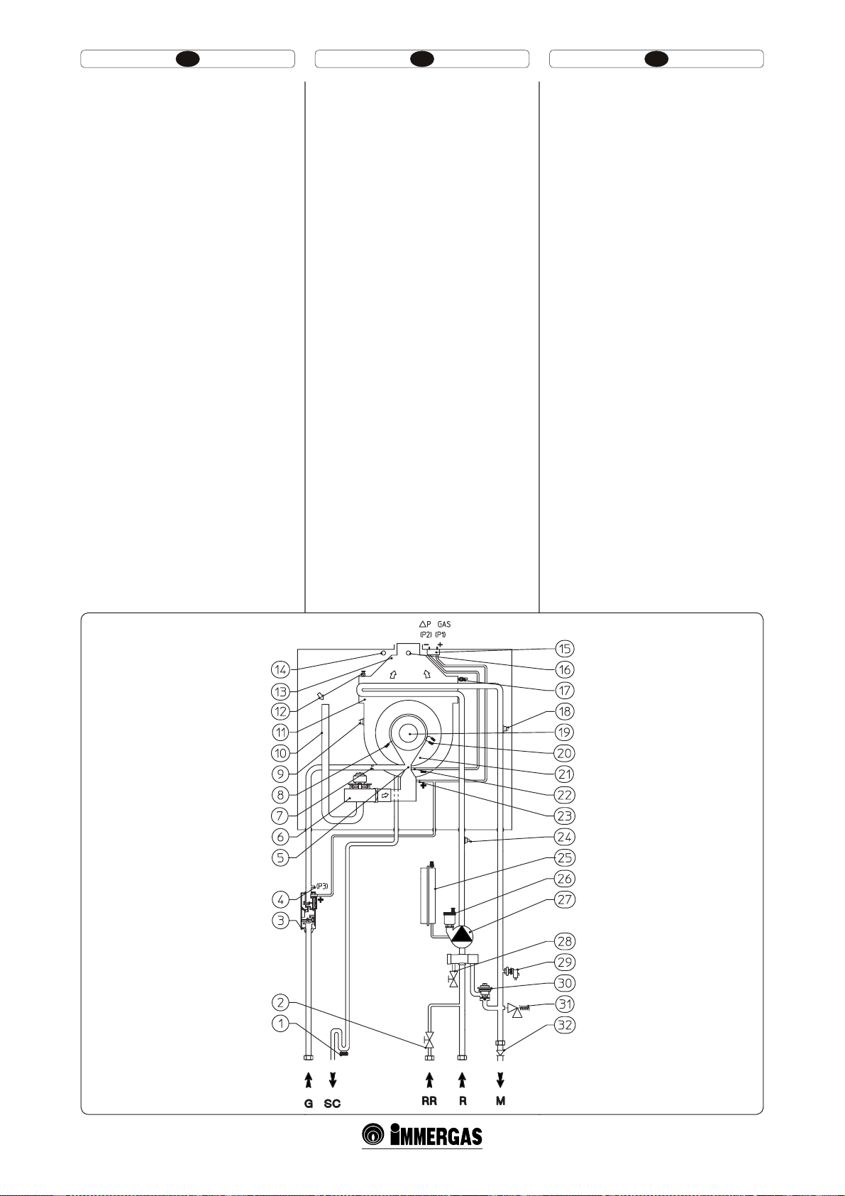
HU IERO
3.1 HIDRAULIKUS SÉMA.
Jelmagyarázat (3-1 ábra):
1 - Kondenz ürítő szifon
2 - Berendezés feltöltő csapja
3 - Gázszelep
4 - Gázszelep kimeneteli nyomásfogó(P3)
5 - Levegő/gáz venturi gyűjtő
6 - Ventilátor
7 - Gázfuvóka
8 - Felmérő gyertyák
9 - Füsttermosztát
10 - Égéslevegő cső
11 - Kondenzációs modul
12 - Kézi légáramlási szelep
13 - Füstcső
14 - Légelemző aknák
15 - ∆p gáznyomásfogó
16 - Füstelemző aknák
17 - Küldő szonda
18 - Biztonsági termosztát
19 - Forraló
20 - Begyújtási gyertyák
21 - Kondenzációs modul fedele
22 - Venturinegatív jelzés (P2)
23 - Venturipozitív jelzés (P1)
24 - Visszacsatlakozási szonda
25 - Berendezés kiterjesztési tartálya
26 - Légáramlás szelepe
27 - Kazán keringető
28 - Berendezés ürítő csapja
29 - Berendezés nyomásmérője
30 - By-pass szabályozható
31 - 3 bar-os biztonsági szelep
32 - Egyirányú szelep
G- Gázellátó
SC - Kondenz kiürítő
RR - Berendezés újrafelöltése
R - Berendezés visszacsatlakozása
M - Berendezés szállítóteljesítménye
3.1 SCHEMA HIDRAULICĂ.
Legendă (Fig. 3-1):
1 - Sifon evacuare apă de condensare
2 - Robinet umplere instalaţie
3 - Valvă gaz
4 - Priză presiune ieşire valvă gaz (P3)
5 - Colector venturi aer/gaz
6 - Ventilator
7 - Duză gaz
8 - Bujie de relevare
9 - Termostat gaze arse
10 - Tub aspirare aer
11 - Modul cu condensare
12 - Valvă evacuare aer manuală
13 - Hotă gaze arse
14 - Puţ de analizare aer
15 - Priză presiune ∆p gaz
16 - Puţ analizator gaze arse
17 - Sondă tur
18 - Termostat siguranţă
19 - Arzător
20 - Bujii de aprindere
21 - Capac modul cu condensare
22 - Semnal negativ venturi (P2)
23 - Semnal pozitiv venturi (P1)
24 - Sondă retur
25 - Vas expansiune instalaţie
26 - Valvă evacuare aer
27 - Circulator centrală
28 - Robinet de golire instalaţie
29 - Presostat instalaţie
30 - By-pass reglabil
31 - Valvă de siguranţă 3 bari
32 - Supapă unidirecţională
G - Alimentare gaz
SC - Evacuare apă de condensare
RR - Umplere instalaţie
R - Retur instalaţie
M - Tur instalaţie
3.1 HYDRAULIC LAYOUT.
Key (Fig. 3-1):
1 - Condensate drain tap
2 - System lling valve
3 - Gas valve
4 - Gas valve outlet pressure point (P3)
5 - Air/gas Venturi collector
6 - Fan
7 - Gas nozzle
8 - Detection electrode
9 - Flue safety thermostat
10 - Air intake pipe
11 - Condensation module
12 - Manual vent valve
13 - Fumes hood
14 - Air sample point
15- ∆p gas pressure point
16 - Flue sample point
17 - Delivery probe
18 - Safety thermostat
19 - Burner
20 - Ignition electrodes
21 - Condensation module cover
22 - Venturi negative sign (P2)
23 - Venturi positive sign (P2)
24 - Return probe
25 - System expansion vessel
26 - Vent valve
27 - Boiler pump
28 - System draining valve
29 - System pressure switch
30 - Adjustable by-pass
31 - 3 bar safety valve
32 - One way valve
G - Gas supply
SC - Condensate drain
RR - System lling
R - System return
M - System delivery
77
3-1
Page 44
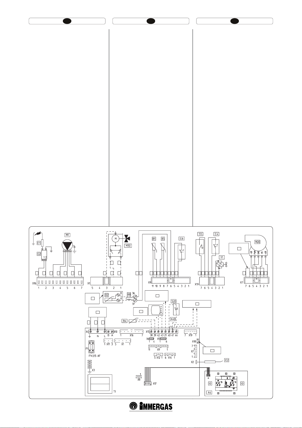
HU IERO
3.2 VILLANYSÉMA.
Jelmagyarázat ( 3-2 ábra):
A4 - Megjelenítési kártya
B1 - Szállító szonda
B2 - Használati víz szonda
B4 - Külső szonda(opcionáisl)
B5 - Visszacsatlakozási szonda
E1 - Begyújtási gyetyák
E2 - Felmérő gyertyák
E4 - Biztonsági termosztát
E6 - Füsttermosztát
F1 - Sorbiztosíték
G2 - Begyújtó
M1 - Kazán keringetője
M20 - Ventilátor
M30 - Három irányú szelep(opcionális)
R8 - Forraló funkciót gátló ellenállás
S5 - Berendezés nyomásmérője
S20 - Környezeti termosztát(opcionálisl)
Super CAR - SUPER távvezérlés
(opcionális)
T1 - Kazán kártya tarnszformátora
X40 - Környezeti termosztát áthidalása
Y1 - Gázzszelep
1 - 230 Vac 50Hz ellátás
2 - Forraló egység (opcionális)
3 - Super távvezérlés (opcionális)
4 - Zónakártya (opcionális)
5 - IMG BUS csatlakozás
6 - Ventilátor fordulatszámai
7 - Sárga / Zöld
8- Kék
9- Barna
10 - Fehér
11 - Lila
12 - Fekete
13 - Vörös
14 - Szürke
15 - Rózsaszín
16 - Narancssárga
17 - Forraló konhurációs hidja
18 - használati víz
19 - fűtés
3.2 SCHEMA ELECTRICĂ.
Legenda (Fig. 3-2):
A4 - Placă de vizualizare
B1 - Sondă tur
B2 - Sondă menajer
B4 - Sondă externă (opţional)
B5 - Sondă retur
E1 - Bujii de aprindere
E2 - Bujie de relevare
E4 - Termostat siguranţă
E6 - Termostat gaze arse
F1 - Fuzibil linie
G2 - Aprinzător
M1 - Circulator centrală
M20 - Ventilator
M30 - Valvă trei căi (opţional)
R8 - Rezistenţă oprire funcţie erbător
S5 - Presostat instalaţie
S20 - Termostat ambient (opţional)
Super CAR - SUPER Comandă Amico
Remoto (opţional)
T1 - Transformator placă centrală
X40 - Punte termostat ambient
Y1 - Valvă gaz
1 - Alimentare 230 Vac 50Hz
2 - Unitate erbător (opţional)
3 - Super Comando Amico Remoto (opţional)
4 - Placă zone (opţional)
5 - Racord IMG BUS
6 - Număr ture ventilator
7 - Galben / Verde
8- Albastru
9- Maro
10 - Alb
11 - Violet
12 - Negru
13 - Roşu
14 - Gri
15 - Roz
16 - Portocaliu
17 - Punte conguraţie erbător
18 - menajer
19 - încălzire
3.2 WIRING DIAGRAM.
Key (Fig. 3-2):
A4 - Display board
B1 - Delivery probe
B2 - Domestic hot water probe
B4 - External probe (optional)
B5 - Return probe
E1 - Ignition electrodes
E2 - Detection electrodes
E4 - Safety thermostat
E6 - Fumes thermostat
F1 - Phase fuse
G2 - Igniter
M1 - Boiler circulating pump
M20 - Fan
M30 - 3-way valve (optional)
R8 - Storage tank function prevention resistan-
ce
S5 - System pressure switch
S20 - Environment thermostat (optional)
Super RFC - SUPER Remote Friend
Control (optional)
T1 - Boiler board transformer
X40 - Environment thermostat jumper
Y1 - Gas valve
1 - 230 Vac 50Hz power supply
2 - Storage unit (optional)
3 - Remote Friend Control (optional)
4 - Zones control unit (optional)
5 - IMG BUS connection
6 - Number of fan revs.
7 - Yellow/Green
8- Blue
9- Brown
10 - White
11 - Purple
12 - Black
13 - Red
14 - Grey
15 - Pink
16 - Orange
17 - Storage tank conguration jumper
18 - domestic hot water
19 - heating
17
19
18
8
9
9
8
8
10
12
11
2
1
7
9
8
13
10
12
10
10
3
8
10
10
12
12
4
14
14
12
5
12
9
8
10
10
6
CH ON
8
10
16
13
15
12
3-2
79
Page 45

HU IERO
Remote vezérlés: a kazán el van látva a Remote
vezérléssel (CAR) vagy alternatívaképpen, Super
Remote Távvezérléssel (Super CAR), amelyeket a
42-es és a 43-as sorkapcsokhoz kell csatlakoztatni
az X5 konektoron az elektronikus kártyán, betartva
a polaritást és az X40 áthidalás kiiktatásával.
A környezeti termosztát: a kazánt fel lehet szerelni
környezeti termosztáttal (S20). Kapcsolja a 40-es és
41-es kapcsokra, kiiktatva az X40 áthidalást.
Forraló egység: a kazán esetenként felszerelhető
egy forraló egységgel is, amelyet a 36 – 37- es
kapcsokhoz kell csatlakoztatni a kapocstáblán (a
műszerfalon) kiiktatva az R8-as ellenállást.
Az X5 konektor a relékártyához való csatlakoztatás
számára való.
Az X6 konektor a személyi számítógéphez való
csatlakoztatás számára való.
Az X8 konektor a szoftver frissítési műveletek
elvégzésére való.
3.3 FELMERÜLŐ HIBÁK ÉS EZEK OKAI.
Megj.: a karbantartási műveleteket csak megfelelő
képesítéssel rendelkező szakember (például az
Immergas szakszerviz munkatársa) végezheti el.
- Gázszag. Oka a gázhálózat csöveinek szivárgása.
Ellenőrizni kell a gázbetáplálás vezetékeinek
tömörségét.
- Ismételt begyújtási zár. Gáz hiánya, ellenőrizze
a hálózatban levő nyomst és, hogy a gázellátó
csap nyitva van. A gázszelep szabályozása nem
a megfelelő, ellenőrizze a gázszelep megfelelő
tartását.
- Szabálytalan égés (piros vagy sárga láng). Oka lehet: bepiszkolódott égő, eltömődött lemezes rész,
helytelenül felszerelt égéslevegő-füstgáz kimenet.
Tisztítsuk meg az előbb említett berendezéseket,
ellenőrizze a levegő-füstgáz csövek megfelelő
telepítését, ellenőrizze a gázszelep megfelelő
tartását (O-Set tárázás) és a füst megfelelő CO2
százalékát.
- A biztonsági határ termosztát gyakori beavatkozása. Oka lehet az alacsony víznyomás
a kazánban, a fűtővíz elégtelen keringése,
a keringtető szivattyú reteszeltsége vagy a
kazán szabályozó kártyájának rendellenessége.
Ellenőrizzük a nyomásmérőn, hogy a fűtési
rendszer víznyomása a megadott határértékek
között van-e. Ellenőrizzük, hogy nincs-e zárva
valamennyi radiátorszelep.
- Elzáródott szifon. Ezt a belsejében lerakódott
szennyeződés vagy égéstermékek okozhatják.
Ellenőrizze a kondenzkiürítő dugó segítségével,
hogy nincsenek jelen a kondenz távozását elzáró
lerakódások.
- Eldugult cserélő. A szifonok eldugulásának következménye lehet ez. Ellenőrizze a
kondenzkiürítő dugó segítségével, hogy nincsenek jelen a kondenz távozását elzáró lerakódások.
- A levegő jelenlétét jelző zaj a berendezésben.
Ellenőrizze a légszelep fedőjének zárását (22.
rész, 1-25 ábra). Ellenőrizze, hogy a berendezés
nyomása és a kiterjedési tartály nyomása megfelel az előírt határértékeknek. A kiterjedési tartály
nyomásértékének 1,0 bar-nak, a berendezésben
levő nyomásértékének 1 és 1.2 bar közötti
értékűnek kell lennie.
- A levegő jelenlétét jelző zaj a kondenzációs
modulban. Használja a manuális légszelepet (16
rész, 1-25 ábra), hogy eltávolítsa az esetenkénti
levegőt a kondenzációs modul belsejében. A
művelet végeztével zárja vissza a kézi légszelepet.
Comenzi de la distanţă: centrala este prevăzută pentru aplicarea Comenzii Amico Remoto (CAR) sau
alternativ a super Comando Amico Remoto (Super
CAR) care trebuie să e legate la bornele 42 şi 43 al
conectorului X15 pe placa electronică respectând
polaritatea şi eliminând puntea X40.
Termostat ambient: centrala este prevăzută pentru
aplicarea Termostatului Ambient (S40). Legaţi-l la
bornele 40 şi 41 eliminând puntea X40.
Unitate fierbător: centrala e prevăzută pentru
aplicarea unei eventuale unităţi fierbător care
trebuie să e racordată la bornele 36-37 ale cutiei
cu borne (aşezată pe tabloul de bord) eliminând
rezistenţa R8.
Conectorul X5 este utilizat pentru racordul la
placa releu.
Conectorul X6 este pentru racordul la computerul
personal.
Conectorul X8 este utilizat pentru operaţiunile de
actualizare soware.
3.3 EVENTUALE INCONVENIENŢE ŞI
CAUZELE LOR.
N.B.: intervenţiile de întreţinere trebuie să e efec-
tuate de un tehnician abilitat (de exemplu Serviciul
Asistenţă Tehnică Immergas).
- Miros de gaz. Este datorat pierderilor din con-
ductele circuitului de gaz. Trebuie verificată
etanşeitatea circuitului de aducţie gaz.
- Blocări aprindere repetate. Absenţa gazului,
vericaţi prezenta presiunii în reţea şi ca robinetul de aducţie a gazului să e deschis. Reglarea supapei gaz incorectă, vericaţi calibrarea
corectă a supapei gaz.
- Combustie iregulară sau zgomote. Poate fi
cauzată de: arzător murdar, parametri de combustie incorecţi, terminal de aspirare – evacuare
neinstalat corect. Efectuaţi curăţarea componentelor de mai sus şi vericaţi instalarea corectă
a terminalului, vericaţi calibrarea corectă a
supapei de gaz (calibrarea O-set) şi procentul
corect de CO2 în gaze arse.
- Intervenţii frecvente ale termostatului de
siguranţă supraîncălzire. Poate depinde de o
presiune redusă a apei în cazan, de circulaţia
redusă în instalaţia de încălzire, de circulatorul
blocat. Vericaţi pe manometru ca presiunea
instalaţiei să e în limitele stabilite. Vericaţi ca
supapele radiatorilor să nu e toate închise şi
funcţionalitatea circulatorului.
- Sifon înfundat. Poate cauzată de depozite de
murdărie sau produse de combustie în interior.
Vericaţi prin intermediul dopului de evacuare
apă de condensare să nu e reziduuri de material
ce obturează trecerea apei de condensare.
- Schimbător obturat. Poate fi o consecinţă a
înfundării sifonului. Vericaţi prin intermediul
dopului de evacuare apă de condensare să nu e
reziduuri de material ce obturează trecerea apei
de condensare.
- Zgomote datorate prezenţei de aer în interiorul
instalaţiei. Vericaţi deschiderea capacului supapei de eliminare aer (Part. 22 Fig. 1-25). Vericaţi
ca presiunea instalaţiei şi a preîncărcării vasului de expansiune să se încadreze în limitele
prestabilite. Valoarea preîncărcării vasului de
expansiune trebuie să e de 1,0 bari, valoare
presiunii instalaţiei trebuie să e cuprinsă între
1 şi 1,2 bari.
- Zgomote datorate prezenţei aerului în interiorul
modulului cu condensare. Utilizaţi supapa de
evacuare aer manuală (Part. 16 Fig. 1-25) pentru
a elimina eventualul aer în interiorul modulului
cu condensare. După efectuarea operaţiunii
închideţi supapa de eliminare aer manuală.
Remote controls: the boiler is designed to use the
Remote Friend Control (RFC) or as an alternative
to the Super Remote Friend Control (Super RFC),
which must be connected to clamps 42 and 43 of
connector X915 on the circuit board, respecting
polarity and eliminating jumper X40.
Room thermostat: the boiler is designed to use the
Room ermostat (S20). Connect it to clamps 40
– 41 eliminating jumper X40.
Storage unit: the boiler is prepared for the application of an eventual storage tank, which must be
connected to clamps 36 - 37 of the terminal board
(on the control panel) eliminating resistance R8.
e connector X5 is used for the connection to
the relay board.
e connector X6 is for connection to a personal
computer.
e connector X8 is used for soware updating
operations.
3.3 TROUBLESHOOTING.
N.B.: Maintenance must be carried out by a quali-
ed technician (e.g. Immergas Technical Assistance
Service).
- Smell of gas. Caused by leakage from gas circuit
pipelines. Check sealing eciency of gas intake
circuit.
- Repeated ignition blocks. No gas, check the presence of pressure in the network and that the gas
adduction valve is open. Incorrect adjustment of
the gas valve, check the correct calibration of the
gas valve.
- Irregular combustion or noisiness. is may be
caused by: a dirty burner, incorrect combustion
parameters, intake-exhaust terminal not correctly installed. Clean the above components and
ensure correct installation of the terminal, check
correct setting of the gas valve (O-Set setting)
and correct percentage of CO2 in fumes.
- Frequent activation of the temperature overload
thermostat. It can depend on the lack of water in
the boiler, little water circulation in the system
or blocked pump. Check on the manometer
that system pressure is within admissible limits.
Check that the radiator valves are not closed and
also the functionality of the pump.
- Trap blocked. is may be caused by dirt or
combustion products deposited inside. Check,
by means of the condensate drain cap, that there
are no residuals of material blocking the ow of
condensate.
- Heat exchanger blocked. is may be caused by
the trap being blocked. Check, by means of the
condensate drain cap, that there are no residuals
of material blocking the ow of condensate.
- Noise due to air in the system. Check opening of
the special air vent valve cap (Part. 22 Fig. 1-25).
Make sure the system pressure and expansion
vessel pre-charge values are within the set limits;
e pre-charge values of the extension vessel
must be 1.0 bar, the value of system pressure
must be between 1 and 1.2 bar.
- Noise due to air inside the condensation module.
Use the manual vent valve (Part. 16 Fig. 1-25)
to eliminate any air present in the condensation
module. When the operation has been performed, close the manual vent valve.
81
Page 46
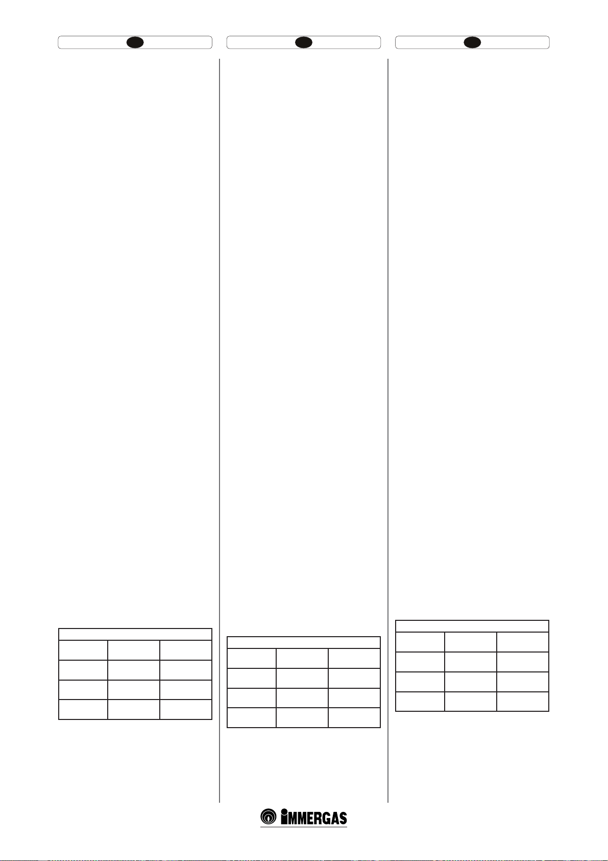
HU IERO
3.4 A KAZÁN ÁTÁLLÁSA MÁS GÁZFA
JTÁRA VALÓ ÁTÁLLÁS ESETÉN.
Abban az esetben, ha az adattáblán feltüntetettől
eltérő gáztípusra szükséges átállítani a készüléket,
meg kell rendelni az átalakításhoz szükséges szerelési csomagot, amely gyorsan elvégezhető.
A más gáztípusra való átállítási munkálatokat csak
képzett szakember (például az Immergas szakszerviz munkatársa) végezheti el.
Az átállásnál az alábbiak a teendők:
- áramtalanítani kell a készüléket;
- ki kell cserélni a fő égőfej fúvókáit, ügyelve
arra, hogy a készletben található tömítő rózsát a
gázcső és a megfelelő fúvókák közé helyezze;
- adjon áramot a berendezésnek;
- végezze el a ventilátor fordulatszámainak
tárázását (3.5 bekezd.):
- szabályozza a megfelelő levegő-gáz arányt (3.6
bekezd.);
- le kell pecsételni a gázhozam beszabályozására
szolgáló berendezést (amennyiben változtatnak
a beállításon);
- az átállítás végeztével fel kell ragasztani az átál-
lítási szerelési csomagban található címkét az
adattábla mellé. Az adattáblán letörölhetetlen
lctollal olvashatatlanná kell tenni a régi gáztípusra utaló adatokat.
A beszabályozást a felhasznált gáztípusnak
megfelelően, táblázat szerint kell elvégezni. (3.18
bekezdés).
3.5 A VENTILÁTOR FORDULATSZÁMAI
NAK TÁRÁZÁSA.
Figyelem: a tárázás ellenőrzésére akkor van szükség,
amikor más gázfájtára állnak át, rendkívüli karbantartás fázisában az elektronikus kártya, a léghálózat,
a gázhálózat alkotó elemeinek kicserélésekor, vagy
a koncentrikus csőnél 1 m-nyire hosszabb füstkémény beszerelésének esetében.
A kazán hőteljesítménye az égéslevegő és a füstgáz
csövek hosszúságától függ. A csövek hosszának
növelésével ez csökken. A kazánon gyárilag be
vannak állítva a csövek minimális hosszai (1m), de
szükség van, főként a csövek maximális extenziója
esetén, a gáz ∆p ellenőrzésére az égő legalább 5
perces működése után névleges teljesítményen,
amikor az égéslevegőben és a füstgázban a levegő
hőmérséklete stabilizálódnak. Szabályozza a használati fázisban a névleges és a minimális teljesítményt (a csatlakoztatott forraló egység nélkül akár)
és a fűtést a táblázat értékei szerint (3.18. bekezd.) a
∆p gáznyomásfogókra csatlakoztatott dierenciális
kapcsolókat használva (13 és 14, 1-25 ábra).
lépjen be a konguráció menübe, a “SEVICE”ben szabályozza a következő paramétereket (3.8
bekezd.):
- “P62” a kazán maximális hőteljesítménye;
- “P63” a kazán minimális hőteljesítménye;
- “P64” fűtés maximális hozama;
- “P65” fűtés minimális hozama;
a következőkben a kazánon jelenlevő default beállítások következnek :
Victrix Superior 32 kW X
MAX. SE-
BESSÉG.
MIN. SEBES-
SÉG
MAX.
KOCKÁZAT.
MIN.
KOCKÁZAT.
G20:
5020 (rpm)
G20:
1260 (rpm)
G20:
5020 (rpm)
G20:
1260 (rpm)
GPL:
4500 (rpm)
GPL:
1000 (rpm)
GPL:
4500 (rpm)
GPL:
1000 (rpm)
3.4 CONVERSIE CENTRALĂ ÎN CAZ DE
SCHIMBARE GAZ.
Dacă aparatul trebuie să se adapteze la un gaz diferit
de cel scris pe plăcuţă, e necesar să solicitaţi kitul
cu cele necesare pentru transformarea care va putea
efectuată rapid.
Operaţiunea de adaptare la tipul de gaz trebuie să
e încredinţată unui tehnician abilitat (de exemplu
Serviciului de Asistenţă Tehnică Immergas).
Pentru a trece de la un tip de gaz la altul e necesar:
- să întrerupeţi tensiunea aparatului;
- să înlocuiţi duza poziţionată între tubul de gaz şi
manşonul de amestecare gaz (Part. 6 Fig. 1-25),
având grijă să eliminaţi tensiunea aparatului în
timpul acestei operaţiuni;
- reporniţi tensiunea în aparat;
- efectuaţi calibrarea numărului de turaţii a ven-
tilatorului (Parag. 3.5):
- reglaţi raportul corect aer gaz (Parag. 3.6);
- sigilaţi dispozitivele de reglare a capacităţii de
gaz (dacă reglările sunt variate);
- o dată efectuată transformarea, puneţi adezivul
prezent în kitul conversiune în aproprierea
plăcuţei cu date. Pe aceasta din urmă trebuie să se
şteargă cu cerneală permanentă datele referitoare
la vechiul tip de gaz.
Aceste reglări trebuie să se refere la tipul de gaz în
uz, urmând indicaţiile tabelelor (parag. 3.18).
3.5 CALIBRARE NUMĂR TURAŢII VENTI
LATOR.
Atenţie: vericarea şi calibrarea este necesară, în caz
de adaptare la alt tip de gaz, în faza de întreţinere
extraordinară cu înlocuirea plăcii electronice, a
componentelor circuitelor de aer, gaz, sau în caz
de instalaţii cu sistem de evacuare a gazelor arse,
având lungimea mai mare de 1 m de tub concentric
orizontal.
Puterea termică a centralei este corelat ă cu lungimea
tuburilor de aspirare aer şi evacuare fumuri. Aceasta
se diminuează în caz de mărire a lungimii tuburilor.
Centrala iese din fabrica reglată pentru lungimea
minimă a tuburilor (1m), este necesar aşadar, mai
ales în caz de extensie maximă a tuburilor să se
verice valorile de ∆p gaz după cel puţin 5 minute
de funcţionare a arzătorului la putere nominală,
când temperaturile aer în instalaţie şi gaz de eva-
cuare s-au stabilizat. Reglaţi puterea nominală şi
minimă în faza menajer (a se efectua fără unitatea
erbător racordată) şi încălzire conform valorilor
din tabelul (Parag. 3.18) utilizând manometre
diferenţiale racordate la prize de presiune ∆p gaz
(13 şi 14 Fig. 1-25).
Intraţi în meniul configuraţii şi în interiorul
rubricii “SEVICE” şi reglaţi următorii parametri
(Parag. 3.8):
- putere termică maximă a centralei “P62”;
- putere termică minimă a centralei “P63”;
- putere maximă de încălzire “P64”;
- putere minimă de încălzire “P65”;
în continuare sun trecute setările din fabrică prezente pe centrală :
Victrix Superior 32 kW X
VITEZĂ.
MAX.
VITZĂ MIN
MAX. RISC.
MIN. RISC.
G20:
5020 (rpm)
G20:
1260 (rpm)
G20:
5020 (rpm)
G20:
1260 (rpm)
GPL:
4500 (rpm)
GPL:
1000 (rpm)
GPL:
4500 (rpm)
GPL:
1000 (rpm)
3.4 CONVERTING THE BOILER TO
OTHER TYPES OF GAS.
If the boiler has to be converted to a dierent gas
type to that specied on the data plate, request
the relative conversion kit for quick and easy
conversion.
Boiler conversion must be carried out by a qualied
technician (e.g. Immergas Technical Assistance
Service).
To convert to another type of gas the following
operations are required:
- remove the voltage from the appliance;
- replace the nozzle located between the gas pipe
and gas/air mixing sleeve (Part. 6 Fig. 1-25),
taking care to remove the voltage from the
appliance during this operation;
- apply voltage to the appliance;
- calibrate the umber of fan revs (Parag. 3.5):
- adjust the correct air/gas ratio (Parag. 3.6);
- seal the gas ow rate devices (if adjusted);
- aer completing conversion, apply the sticker,
present in the conversion kit, near the data-plate.
Using an indelible marker pen, cancel the data
relative to the old type of gas.
ese adjustments must be made with reference
to the type of gas used, following that given in the
table (Parag. 3.18).
3.5 CALIBRATION OF NUMBER OF FAN
REVS.
Important: Verication and calibration is necessa-
ry, in the case of transformation to other types of
gas, in the extraordinary maintenance phase with
replacement of the circuit board, air/gas circuit
components or in the case of installations with fume
extraction systems, with horizontal concentric pipe
measuring more than 1 metre.
e boiler heat output is correlated to the length of
the air intake and ue exhaust pipes. is decreases
with the increase of pipe length. e boiler leaves
the factory adjusted for minimum pipe length (1m).
It is therefore necessary, especially in the case of
maximum pipe extension, to check the ∆p gas values aer at least 5 minutes of burner functioning at
nominal heat output, when the temperatures of the
intake air and exhaust fumes have stabilised. Adjust
the nominal and minimum heat output in the
domestic hot water (to also be performed without
the storage tank connected) and heating modes
according to the values in the table (Par. 3.18) using
the dierential manometers connected to the ∆p gas
pressure point (13 and 14 Fig. 1-25).
Enter the congurations menu under the “SERVICE” item and adjust the following parameters
(Parag. 3.8):
- adjust the boiler maximum heat output “P62”;
- adjust the boiler minimum heat output “P63”;
- maximum heating output “P64”;
- minimum heating output “P65”;
Below find the default settings present on the
boiler :
Victrix Superior 32 kW X
SPEED MAX.
MIN SPEED
MAX. HEAT.
MIN. HEAT.
G20:
5020 (rpm)
G20:
1260 (rpm)
G20:
5020 (rpm)
G20:
1260 (rpm)
GPL:
4500 (rpm)
GPL:
1000 (rpm)
GPL:
4500 (rpm)
GPL:
1000 (rpm)
83
Page 47
HU IERO
3.6 LEVEGŐ ÉS GÁZ ARÁNYÁNAK
SZABÁLYOZÁSA.
Figyelem:A CO
zerelt védőráccsal lehet elvégezni, míg a gázszelep
tárázási műveleteit nyitott védőráccsal lehet elvégzeni és a kazánt az ellátásról lekapcsolva.
minimum tárázása (minimális fűtési telje-
CO
2
sítmény).
Lépjen be a kéményseprő fázisba anélkül, hogy
használati vízszolgáltatást végezne el, és a fűtés kiválasztót állítsa minimumra (az óramutató járásával
ellentétes irányba, míg a display-en megjelenik a
“0”). A füst CO
nikusnak az alapig be kell helyeznie a mérőszondát
a vételi résbe, tehát ellenőrizze, hogy a CO
az, amely a következő táblán megjelenik, ellenkező
esetben szabályozza a csavarokat (3, 3-3 ábra) (OSet szabályozó). A CO
forgassa a szabályozó csavarokat (3) az óramutató
járásával megegyező irányba, és fordítva, ha csökkenteni kívánja.
CO
maximum tárázása (minimális fűtési telje-
2
sítmény).
A minimum CO
kéményseprő funkció fenntartásával helyezze a
fűtéskiválasztót a maximumra (forgassa az óramutató járásával megegyező irányba, míg a display-en
megjelenik a “99”). A füst CO
eléréséhez a technikusnak az alapig be kell helyeznie
a mérőszondát a vételi résbe, tehát ellenőrizze, hogy
a CO
érték az, amely a következő táblán megjele-
2
nik, ellenkező esetben, szabályozza a csavarokat (12,
3-3 ábra)(gázhozamszabályozó).
A CO
2
szabályozó csavarokat (12) az óramutató járásával
megegyező irányba, és fordítva, ha csökkenteni
kívánja.
Minden egyes szabályozásvariációban a 12 csavarokon meg kell vérni, hogy a kazán állandósul a
beállított értéken (kb. 30 másodperc).
ellenőrzési műveleteit egy bes-
2
pontos értékének eléréséhez a tech-
2
érték
2
érték növelése érdekében
2
szabályozásának végén, a
2
pontos értékének
2
érték növelése érdekében forgassa a
CO2 névleges telje-
sítményen (fűtés)
CO2 minimális
teljesítményen
(fűtés)
G 20 9,40% ± 0,2 9,05% ± 0,2
G 30 12,30% ± 0,2 11,70% ± 0,2
G 31 10,40% ± 0,2 10,10% ± 0,2
G25.1 10,70% ± 0,2 10,45% ± 0,2
3.7 A GÁZÁTÁLLÁS UTÁNI
ELLENŐRZÉSEK.
Miután meggyőződtünk, hogy az átálláshoz a
gáztípusra előírt átmérőjű fúvóka került beszerelésre, és a beállítás az előírt nyomáson történt,
ellenőrizni kell: - hogy az égő lángja ne legyen túl
magas vagy alacsony, és stabil legyen (ne távolodjék
el az égőtől);
Megj.: a kazán beszabályozási műveleteit csak
megfelelő képesítéssel rendelkező szakember
(például az Immergas szakszerviz munkatársa)
végezheti el.
3.6 REGLAREA RAPORTULUI AERGAZ.
Atenţie: operaţiunile de vericare a CO2 sunt făcute
cu carcasa montată, în timp ce operaţiunile de calibrare a supapei gaz sunt făcute cu carcasa deschisă
şi întrerupând tensiunea în centrala.
Calibrarea CO
Întraţi în faza de curăţare hornuri fără a efectua
preluări de apă menajeră şi duceţi selectorul
încălzire la minim (rotiţi-l în sens invers acelor e
ceasornic până apare pe ecran”0”). Pentru a avea o
valoare exactă a CO2 în gaze arse este necesar ca
tehnicianul să insereze aducând sonda de preluare
în puţ, pentru a verica ca valoarea CO2 să e cea
indicată în tabelul următor, în caz contrar reglaţi
pe şurub (3 Fig. 3-3) (reglator O-Set). Pentru a
mări valoarea de CO2 este necesar să rotiţi şurubul
de reglare (3) în sens orar şi invers dacă se doreşte
diminuarea.
Calibrarea CO
încălzire).
La terminarea reglării CO
funcţia curăţare coşuri activă duceţi selectorul
încălzire la maxim (rotiţi-l în sensul acelor de ceasornic până vizualizaţi ”99” pe display). Pentru a
avea o valoare exactă a CO
ca tehnicianul să insereze adânc sonda de preluare
în puţ, pentru a verica ca valoarea CO
indicată în tabelul următor, în caz contrar reglaţi pe
şurub (12 Fig. 3-3) (reglator putere gaz).
Pentru a mări valoarea de CO
şurubul de reglare (12) în sens antiorar şi viceversa
dacă se doreşte micşorarea.
La ecare variere a reglării pe şurub 12 este necesar
să aşteptaţi ca centrala să se stabilizeze la valoare
setată (circa 30 sec).
minim (putere minimă încălzire).
2
maxim (putere nominală de
2
minim menţinând
2
în gaze arse este necesar
2
să e cea
2
e necesar să rotiţi
2
CO2 la putere nominală
(încălzire)
CO
la putere
2
minimă (încălzire)
G 20 9,40% ± 0,2 9,05% ± 0,2
G 30 12,30% ± 0,2 11,70% ± 0,2
G 31 10,40% ± 0,2 10,10% ± 0,2
3.7 CONTROALE DE EFECTUAT DUPĂ
CONVERSIUNILE GAZULUI.
După asigurarea că transformarea a fost făcută
cu duza de diametrul prestabilit pentru tipul de
gaz utilizat şi calibrarea a fost făcută la presiunea
stabilită, trebuie să vă asiguraţi că acăra arzătorului
să nu e excesiv de mare şi că este stabilă (nu se
desprinde de arzător);
N.B.: toate operaţiunile privind reglările centralelor
trebuie să e efectuate de un tehnician abilitat ( de
exemplu Serviciul Asistenţă Immergas).
3.6 ADJUSTMENT OF THE AIRGAS RA
TIO.
Important: the verication operations of the CO
must be carried out with the casing mounted, while
the gas valve calibration operations must be carried
out with the casing open and removing the voltage
from the boiler.
Calibration of the minimum CO
heating power).
Enter the chimney sweep phase without withdrawing domestic hot water and take the selector
switches to minimum (turn them in an anticlockwise direction until “0” is seen on the display).
o have an exact value of CO
nician must insert the sampling probe to the bottom
of the sample point, then check that the CO
is that specied in the table, otherwise adjust the
screw (3 Fig. 3-3) (O-Set adjuster). To increase
the CO
value, turn the adjustment screw (3) in a
2
clockwise direction and vice versa to decrease it.
Calibration of the maximum CO2 (nominal heating power).
On completion of the adjustment of the minimum
CO2 keeping the chimney sweep function active,
take the heating selector switch to maximum (turn
it in a clockwise direction until “99” is seen on the
display). To have an exact value of CO
the technician must insert the sampling probe to the
bottom of the sample point, then check that the CO
value is that specied in the table, otherwise adjust
the screw (12 Fig. 3-3) (Gas ow adjuster).
To increase the CO2 value, turn the adjustment
screw (12) in an anti-clockwise direction and vice
versa to decrease it.
At every adjustment variation on the screw 12 it is
necessary to wait for the boiler to stabilise itself at
the value set (about 30 sec.).
CO2 at nominal
output (heating)
(minimum
2
in the fumes the tech-
2
value
2
in the fumes
2
CO2 at minimum
output (heating)
G 20 9,40% ± 0,2 9,05% ± 0,2
G 30 12,30% ± 0,2 11,70% ± 0,2
G 31 10,40% ± 0,2 10,10% ± 0,2
3.7 CHECKS FOLLOWING CONVERSION
TO ANOTHER TYPE OF GAS.
Aer making sure that conversion was carried out
with a nozzle of suitable diameter for the type of gas
used and the settings are made at the correct pressure, check that the burner ame is not too high or low
and is stable (does not detach from burner);
N.B.: All boiler adjustment operations must be
carried out by a qualied technician (e.g. Immergas
Assistance Service).
2
2
85
Page 48

HU IERO
3.8 AZ ELEKTRONIKUS KÁRTYA PRO
GRAMÁLÁSA.
Az Victrix Superior kW X kazán úgy lett gyárilag kialakítva, hogy lehetőség van egyes működési paraméterek programozására. Amennyiben a következőkben
leírt módon módosítja ezeket a paramétereket, a
kazánt egyéni igényeihez igazíthatja.
Figyelem: amennyiben a nemzetközi nyelv (A1) visszaállítását szándékozza megtenni, lásd a 2.13 bekezdésben levő utasításokat (Perszonalizációk menü)
A “D” gomb benyomásával be lehet lépni három
fő részre felosztott főmenübe:
- Információk “M1” (Lásd “Felhasználó” fejeze-
tet)
- perszonalizációk “M3”( Lásd “Felhasználó”
fejezetet).
- Kongurációk“M5” a technikus számára fen-
ntartott menü, amelyhez belépési kódra van
szüksége.
A programba való belépéshez nyomja be a “D”
gombot, forgassa el a (3) hőmérsékletkiválasztót,
és futassa le a menüsort, míg eléri az “M5”öt, majd
nyomja be a “D” gombot, vigye be a belépési kódot
és állítsa be tetszés szerint a paramétereket.
A következőkben az “M5” menüsor jelenik meg, a
default paraméterek megjelelölésével és a lehetséges
opciókkal.
A (3) fűtéshőmérsékletkiválasztó elforgatásával
lefutnak a menüsorok, a “D” gomb benyomásával
be kehet lépni a menü különböző szintjeire és meg
lehet erősíteni a paraméterek kiválasztását. A “C”
gomb benyomásával vissza lehet egy szintet lépni.
(Az opciók első sora, amely megjelenik a paraméterben, a default által kiválasztott.).
3.8 PROGRAMARE PLACĂ
ELECTRONICĂ.
Centrala Victrix Superior kW X este prevăzută
pentru o eventuală programare a unor parametri de
funcţionare. Modicând aceşti parametri cum e descris mai sus va posibilă adaptarea centralei conform
cerinţelor specice.
Atenţie: în cazul în care se intenţionează restabilirea
limbii internaţionale (A1), consultaţi indicaţiile descrise la Parag. 2.13 (Meniu personalizări)
Prin apăsarea butonului ”D” este posibilă accesarea meniului principal subdivizat în trei părţi
principale:
- Informaţii “M1” (Vezi capitol “Utilizator”)
- personalizări “M3”(Vezi capitol “Utilizator”).
- Conguraţii ” M5” meniu rezervat tehnicianului
pentru care este necesar un cod de acces.
Pentru a accede la programare apăsaţi butonul
”D”, rotiţi selectorul temperatură încălzire (3) şi
deplasaţi-vă pe rubricile meniului până ajungeţi
la rubrica M5”, apăsaţi butonul ”D”, introduceţi
codul de acces şi setaţi parametrii conform propriilor cerinţe.
În continuare sunt trecute rubricile meniului M5”
cu indicarea parametrilor de fabrică şi posibilele
opţiuni.
Prin rotirea selectorului temperatură încălzire (3) se
deplasează rubricile meniurilor, prin apăsarea butonului ”D” se accede la diferitele nivele din meniuri
şi se conrmă alegerea parametrilor. Prin apăsarea
butonului ”C” se întoarce înapoi la un nivel.
(Prima rubrică a diferitelor opţiuni ce apare în interiorul parametrului este cea selectată din fabrică).
3.8 PROGRAMMING THE CIRCUIT BO
ARD.
e Victrix Superior kW X boiler is prepared for possible programming of several operation parameters.
By modifying these parameters as described below, the
boiler can be adapted according to specic needs.
Important: If the international language is to be
restored (A1), see the indications described in Par.
2.13 (Customisations menu)
By pressing the button “D” it is possible to access the
main menu, divided into three main parts:
- Information“M1” (See “User” Chapter)
- Information“M3” (See “User” Chapter).
- “M5” congurations, menu reserved for the tech-
nician and for which a password is required.
To access programming, press button “D”, turn the
heating temperature selector switch (3) and scroll
through the menu items until reaching “M5”, press
button “D”, introduce the password and set the
parameters according to requirements.
Below nd the items in the“M5” menu with default
parameters and possible options indicated.
By turning the heating temperature selector switch
(3) scroll through the menu items. By pressing
button “D” access the various levels of the menu
and the choice of parameters is conrmed. Press
button “C” to go back one level.
(e rst item of the various options that appears
inside the parameter is that selected by default).
87
Page 49

HU
(be kell vinni a belépési kódot)
1° szint 2° szint Opciók Leírás Default érték
24 KW
P53
P54
P55
SERVICE
28 KW
32 KW
P54.1
P54.2
P54.3 Megjeleníti a visszacsatlakozási szondáról leolvasott hőmérsékletet - -
P57
AUT O
P62 4000 ÷ 5500
P63 1000 ÷ 1500
P64 ≤ P62
P65 ≥ P63
P66/A
P66/B
P66
P66/C
P66/D
Azonosítja a kazán teljesítményét, amelyen az elektronikus kártya be van
szerelve
Megjeleníti a leolvasott hőmérsékletet a forraló szondájáról (amennyiben
jelen van külső forraló egység)
Nem alkalmazott --
Megjeleníti a fűtés szállító hőmérsékletét, amellyel a kazán működik, a
berendezés hőszabályozóján levő aktív ellenőrzések által kiszámítottakat
1 Első fűtési sebesség
2 Második fűtési sebesség
3 Harmadik fűtési sebesség
Automatikus keringető sebessége. Be kell állítani a ∆T a berendezés visszacsatlakozása és szállítása között (beállítható 5-től 25 K-ig)
Beállítja a használati víz funkció maximális teljesítményét (amennyiben
jelen van külső forraló egység), beállítva ventilátor sebességét (RPM fordulatok másodpercenként).
Beállítja a használati víz funkció minimális teljesítményét (amennyiben
jelen van külső forraló egység), beállítva ventilátor sebességét (RPM fordulatok másodpercenként)
Beállítja a környezeti fűtés működésének maximális teljesítményét. Az
értékenek P62 –nél kisebbnek, vagy ezzel egyenlőnek kell lennie
IBeállítja a környezeti fűtés működésének minimális teljesítményét. Az
értékenek P63 –nál kisebbnek, vagy ezzel egyenlőnek kell lennie
A külső szonda (opció) nélkül meghatározza a minimális szállítási
hőmérsékletet. A jelenlevő külső szondával meghatározza a minimális
szállítási hőmérsékletet a maximális külső hőmérséklettel működésnek
megfelelően (lásd 1-9 ábra grakonját) (beállítható 25°C és 50°C között)
MEGJ.: ehhez meg kell erősíteni a paramétert (nyomja be a “D”-t vagy a
“C” benyomásával lépjen ki a “P66” szabályozásból)
A külső szonda (opció) nélkül meghatározza a maximális szállítási
hőmérsékletet. A jelenlevő külső szondával meghatározza a maximális
szállítási hőmérsékletet a maximális külső hőmérséklettel működésnek
megfelelően (lásd 1-9 ábra grakonját) (beállítható 50°C és 85°C között)
MEGJ.: ehhez meg kell erősíteni a paramétert (nyomja be a “D”-t vagy a
“C” benyomásával lépjen ki a “P66” szabályozásból)
A jelenlevő külső szondával meghatározza, hogy a minimális külső
hőmérséklettel a kazánnak maximális szállítási hőmérséklettel kell
működnie (lásd 1-9 ábra grakonját) (beállítható -20°C és 0°C között)
MEGJ.: ehhez meg kell erősíteni a paramétert (nyomja be a “D”-t vagy a
“C” benyomásával lépjen ki a “P66” szabályozásból)
A jelenlevő külső szondával meghatározza, hogy a maximális külső
hőmérséklettel a kazánnak minimális szállítási hőmérséklettel kell
működnie (lásd 1-9 ábra grakonját) (beállítható 5°C és +25°C között)
MEGJ.: ehhez meg kell erősíteni a paramétert (nyomja be a “D”-t vagy a
“C” benyomásával lépjen ki a “P66” szabályozásból)
Menü M5
Egyenlő a kazán
teljesítményével
--
--
AUT O
15 K
(lásd a 3.5
bekezd)
(lásd a 3.5
bekezd)
(lásd a 3.5
bekezd)
(lásd a 3.5
bekezd)
25°C
85°C
-5°C
25°C
A technikus
által beál-
lított érték
Egyenlő a
kazán teljesítményével
94
Page 50

HU
(be kell vinni a belépési kódot)
1° szint 2° szint Opciók Leírás Default érték
P67.1 Téli modalitásban a keringető mindig ellátás alatt áll, tehát mindig működik
P67
P67.3
P68 0s ÷ 500s
P69 0s ÷ 255s
P70 0s ÷ 840s
P71.1
P71
P72
(-3°C)
P71.2
(-10°C)
AUT O
OFF
08 L/M
10 L/M
12 L/M
RELE1.OFF 1 relé nem alkalmazott
Téli modalitásban a keringetőt a környezeti termosztát vagy a remote távvezérlés kezeli
Téli modalitásban a keringetőt a környezeti termosztát vagy a remote távvezérlés, és a kazán szállítási szondája kezeli
A kazán be van arra állítva, hogy bekapcsolja az égőt azonnal a környezeti
fűtést követően. Sajátságos berendezések esetén (pl. zónás berendezés motorizált szelepekkel, stb.) a bekapcsolás lehet, hogy késleltetve van
A kazán el van látva egy elektromos időmérővel, amely megakadályozza az
égő gyakori bekapcsolását a fűtési fázisban
A kazán egy sor bekapcsolást alkalmaz, hogy elérjen a minimális
fűtésteljesítménytől a névleges fűtésteljesítményig
A kazán használati víz melegítése (amennyiben jelen van külső forraló
egység) akkor kapcsol be, amikor a forralóban levő víz hőmérséklete 3°C-al
sülyed a beállított értékhez képest.
A kazán használati víz melegítése (amennyiben jelen van külső forraló
egység) akkor kapcsol be, amikor a forralóban levő víz hőmérséklete 10°C -al
sülyed a beállított értékhez képest.
Ez a funkció elhanyagolható a kazán ebben a modalitásban való megfelelő
működése érdekében.
Menü M5
P67.2P67.2
0 másodperc
180 máso-
dperc
840 máso-
dperc
(14 perc)
P71.2
AUT O
A technikus
által beál-
lított érték
SERVICE
RELE1.1 Egy zónákra felosztott berenedezében az 1 relé a főzónát vezérli
RELE1
(opcionális)
RELE2
(opcionális)
RELE3
(opcionális)
P76 -10°C ÷ +10°C
RELE1.2
RELE1.3
RELE1.4
RELE2.OFF 2 relé nem használt
RELE2.6
RELE2.2
RELE2.3
RELE2.4
RELE2.5 Egy zónákra felosztott berendezésben a 2 relé vezérli a másodlagos zónát
RELE3.OFF 3 relé nem használt
RELE3.7
RELE3.2
RELE3.3
RELE3.4
A relé jelzi a kazán leállásának jelenlétét (egy nem szállított, külső jelzővel
párosítható)
A relé jelzi, hogy a kazán be van kapcsolva (egy nem szállított, külső jelzővel
párosítható)
Egy külső gázszelep nyitását vezérli, egy, a kazán égőjének bekapcsolási
kérésével
A 2 relé aktiválja a remote újrafeltöltés villanyszelepét (Opciónális) A vezérlés
a remote távvezérléstől ered
Az 1 relé jelzi A relé jelzi a kazán leállásának jelenlétét (egy nem szállított,
külső jelzővel párosítható)
Az 1 relé jelzi, hogy a kazán be van kapcsolva (egy nem szállított, külső
jelzővel párosítható)
Egy külső gázszelep nyitását vezérli, egy, a kazán égőjének bekapcsolási
kérésével
Ellenőrzi a bojler újrakeringető szivattyúját (amennyiben jelen van külső
forraló egység).
A relé jelzi A relé jelzi a kazán leállásának jelenlétét (egy nem szállított, külső
jelzővel párosítható)
A relé jelzi, hogy a kazán be van kapcsolva (egy nem szállított, külső jelzővel
párosítható)
Egy külső gázszelep nyitását vezérli, egy, a kazán égőjének bekapcsolási
kérésével
Abban az esetben, amikor a külső szonda olvasat nem megfelelő, az esetenkénti
környezeti tényezők kompenzációjaképpen ki lehet igazítani
RELE1.1
RELE2.OFF
RELE3.OFF
0°C
95
Page 51

RO
(este necesar să se insereze codul de acces)
1° Nivel 2° Nivel Opţiuni Descriere
24 KW
P53
P54
P55
SERVICE
28 KW
32 KW
P54.1
P54.2
P54.3 Vizualizează temperatura citită pe sonda de retur - -
P57
AUT O
P62 4000 ÷ 5500
P63 1000 ÷ 1500
P64 ≤ P62
P65 ≥ P63
P66/A
P66/B
P66
P66/C
P66/D
Identică puterea centralei pe care este instalată placa electronică
Vizualizează temperatura citită pe sonda erbător (dacă este prezentă o
unitate erbător externă)
Neutilizat --
Vizualizează temperatura de tur încălzire la care centrala funcţionează,
calculată de controalele active pe termoreglare instalaţie
1 Prima viteză încălzire
2 A doua viteză încălzire
3 A treia viteză încălzire
Viteză circulator automată. Trebuie setată valoarea de ∆T între tur şi retur
instalaţie (setabilă de la 5 la 25 K)
Setează puterea maximă în funcţionare menajer (dacă e prezentă o unitate
erbător externă) setând viteza ventilatorului (în turaţii pe minut RPM)
Setează puterea minimă în funcţionare menajer (dacă e prezentă o unitate
erbător externă) setând viteza ventilatorului (în turaţii pe minut RPM
Setează puterea maximă în funcţionare încălzire ambient. Valoarea trebuie
să e inferioară sau egală cu P62
Setează puterea minimă în funcţionare încălzire ambient. Valoarea trebuie
să e minoră sau egală cu P63
Fără sonda externă (opţional) deneşte temperatura de tur minimă. Cu
soda externă prezentă deneşte temperatura minimă de tur ce corespunde
funcţionării cu temperatura externă maximă (vezi grac Fig. 1-9) (setabil
de la 25°C la 50°C) N.B.: pentru a continua e necesar să conrmaţi parametrul (apăsaţi ”D” sau ieşiţi din reglarea de “P66” apăsând ”C”
Fără sonda externă (opţional) deneşte temperatura de tur maximă. Cu
soda externă prezentă deneşte temperatura maximă de tur ce corespunde
funcţionării cu temperatura externă minimă (vezi grac Fig. 1-9) (setabil
de la 25°C la 50°C) N.B. pentru a continua e necesar să conrmaţi parametrul (apăsaţi ”D” sau ieşiţi din reglarea de “P66” apăsând ”C”
Cu sonda externă prezentă deneşte la ce temperatură externă minimă trebuie să funcţioneze centrala la temperatura de tur (vezi grac Fig. 1-9) (reglabil de la -20°C la 0°C) N.B.: pentru a continua e necesar să conrmaţi
parametrul (apăsaţi ”D” sau ieşiţi din reglarea de “P66” apăsând ”C”
Cu sonda externă prezentă deneşte la ce temperatură externă maximă
trebuie să funcţioneze centrala la temperatura de tur (vezi grac Fig. 1-9)
(reglabil de la 5°C la +25°C) N.B.: pentru a continua e necesar să conrmaţi
parametrul (apăsaţi ”D” sau ieşiţi din reglarea de “P66” apăsând ”C”
Meniu M5
Valoare de
fabrică
Egal cu puterea
centralei
--
--
AUT O
15 K
(Vezi parag. 3.5)
(Vezi parag. 3.5)
(Vezi parag. 3.5)
(Vezi parag. 3.5)
25°C
85°C
-5°C
25°C
Valoare
setată de
tehnician
Egal cu
puterea
centralei
96
Page 52

RO
(este necesar să se insereze codul de acces)
1° Nivel 2° Nivel Opţiuni Descriere
P67.1
P67
P67.3
P68 0s ÷ 500s
P69 0s ÷ 255s
P70 0s ÷ 840s
P71.1
P71
P72
(-3°C)
P71.2
(-10°C)
AUT O
OFF
08 L/M
10 L/M
12 L/M
RELE1.OFF Releu 1 neutilizat
În modalitatea iarnă circulatorul este mereu alimentat şi deci mereu în
funcţiune
În modalitatea iarnă circulatorul este controlat de termostatul ambient sau de
comanda de la distanţă
În modalitatea iarnă circulatorul este controlat de termostatul ambient sau de
comanda de la distanţă şi de la sonda de tur a centralei
Centrala este setată pentru a porni arzătorul imediat după o solicitare de
încălzire ambient. În caz de instalaţii particulare (ex. instalaţii pe zone cu
supape motorizate etc.) ar putea necesară întârzierea pornirii
Centrala este dotată cu un temporizator electronic ce împiedică pornirile
frecvente ale arzătorului în faza de încălzire
Centrala efectuează o rampă de pornire pentru a sosi de la puterea minimă la
puterea nominală de încălzire
Pornirea centralei pentru încălzirea apei menajere (dacă e prezentă o unitate
erbător externă) are loc când apa din erbător coboară cu 3°C faţă de
temperatura setată.
Pornirea centralei pentru încălzirea apei menajere (dacă e prezentă o unitate
erbător externă) are loc când apa din erbător coboară cu 10°C faţă de
temperatura setată.
Această funcţie nu are importanţă pentru funcţionarea corectă a acestui
model de centrală.
Meniu M5
Valoare de
fabrică
P67.2P67.2
0 secunde
180 secunde
840 secunde
(14 minute)
P71.2
AUT O
Valoare
setată de
tehnician
SERVICE
RELE1.1 O instalaţie divizată în zone releul 1 comandă zona principală
RELE1
(opţional)
RELE2
(opţional)
RELE3
(opţional)
P76 -10°C ÷ +10°C
RELE1.2
RELE1.3
RELE1.4
RELE2.OFF Releu 2 neutilizat
RELE2.6
RELE2.2
RELE2.3
RELE2.4
RELE2.5 O instalaţie divizată în zone releul 2 comandă zona secundară
RELE3.OFF Releu 3 neutilizat
RELE3.7
RELE3.2
RELE3.3
RELE3.4
Releul semnalează intervenţia unei blocări în centrală (cuplată la un semnalizator extern nefurnizat)
Releul semnalizează că centrala e pornită (cuplată la un semnalizator extern
nefurnizat)
Comandă deschiderea unei supape de gaz externă concomitent cu o cerere de
pornire a arzătorului în centrală
Releul 2 activează electrovalva de umplere de la distanţă (Opţional). Comanda se face de la o comandă de la distanţă
Releul semnalează intervenţia unei blocări în centrală (cuplată la un semnalizator extern nefurnizat)
Releul semnalizează că centrala e pornită (cuplată la un semnalizator extern
nefurnizat)
Comandă deschiderea unei supape de gaz externă concomitent cu o cerere de
pornire a arzătorului în centrală
Controlează pompa de recirculare boiler (dacă e prezentă o unitate erbător
externă)
Releul semnalează intervenţia unei blocări în centrală (cuplată la un semnalizator extern nefurnizat)
Releul semnalizează că centrala e pornită (cuplată la un semnalizator extern
nefurnizat)
Comandă deschiderea unei supape de gaz externă concomitent cu o cerere de
pornire a arzătorului în centrală
În cazul în care citirea sondei externe nu este corectă se poate corecta pentru a
compensa eventualii factori de mediu
RELE1.1
RELE2.OFF
RELE3.OFF
0°C
97
Page 53

IE
menu (password must be entered)
1° Level 2° Level Options Description Default value
24 KW
P53
P54
P55
SERVICE
28 KW
32 KW
P54.1
P54.2
P54.3 Displays the temperature read on the return probe - -
P57
AUT O
P62 4000 ÷ 5500
P63 1000 ÷ 1500
P64 ≤ P62
P65 ≥ P63
P66/A
P66/B
P66
P66/C
P66/D
Identies the power of the boiler on which the circuit board is installed
Displays the temperature read on the storage tank probe (if an external
storage unit is present)
Not used --
Displays the heating delivery temperature at which the boiler functions,
calculated by the controls active on the system heat adjustment
1 First heating speed
2 Second heating speed
3 ird heating speed
Automatic pump speed. e ∆T value must be set between system delivery
and return (can be set from 5 to 25K)
Sets the maximum output in the domestic hot water mode (if an external
storage unit is present), setting the speed of the fan (in RPM)
Sets the minimum output in the domestic hot water mode (if an external
storage unit is present), setting the speed of the fan (in RPM)
Set the maximum output depending on room heating. e value must be
less than or equal to P62
Set the minimum output depending on room heating. e value must be
greater than or equal to P63
Without the external probe (optional) it denes the minimum delivery
temperature. With the external probe present it denes the minimum delivery temperature corresponding to functioning with maximum external
temperature (see graphics Fig. 1-9) (can be set from 25°C to 50°C)N.B.: to
continue it is necessary to conrm the parameter (press “D” or exit from
“P66” adjustments by pressing “C”)
Without the external probe (optional) it denes the maximum delivery
temperature. With the external probe present it denes the maximum delivery temperature corresponding to functioning with minimum external
temperature (see graphics Fig. 1-9) (can be set from 50°C to 85°C)N.B.: to
continue it is necessary to conrm the parameter (press “D” or exit from
“P66” adjustments by pressing “C”)
With the external probe present it denes at which minimum external
temperature the boiler must function at maximum delivery temperature
(see graphics Fig. 1-9) (can be set from -20°C to 0°C)N.B.: to continue
it is necessary to conrm the parameter (press “D” or exit from “P66”
adjustments by pressing “C”)
With the external probe present it denes at which maximum external
temperature the boiler must function at the minimum delivery temperature (see graphics Fig. 1-9) (can be set from 5°C to +25°C)N.B.: to continue
it is necessary to conrm the parameter (press “D” or exit from “P66”
adjustments by pressing “C”)
M5
Equal to boiler
power
--
--
AUT O
15 K
(See par. 3.5)
(See par. 3.5)
(See par. 3.5)
(See par. 3.5)
25°C
85°C
-5°C
25°C
Value set by
technician
Equal to
boiler
power
98
Page 54

IE
menu (password must be entered)
1° Level 2° Level Options Description
P67.1 In winter mode the pump is always powered and so functions continuously
In winter mode the pump is managed by the room thermostat or by the
remote control
In winter mode the pump is managed by the room thermostat or by the
remote control and by the boiler delivery probe
e boiler is set to ignite the burner immediately aer a request for heating.
In the case of particular systems (e.g. area systems with motorised thermostatic valves etc.) it could be necessary to delay switch-on
e boiler has an electronic timing device that prevents the burner from
igniting too oen in the heating phase
e boiler performs an ignition ramp to arrive from minimum power to
nominal heat output
e ignition of the boiler for heating of the domestic hot water (if an external
storage unit is present) occurs when the water contained in the storage tank
falls by 3°C with respect to the temperature set
e ignition of the boiler for heating of the domestic hot water (if an external
storage unit is present) occurs when the water contained in the storage tank
falls by 10°C with respect to the temperature set
is function has no inuence on the correct functioning of this boiler model AUT O
e relay signals the intervention of boiler block ( Can be coupled to an
external signalling device, not supplied)
e relay signals that the boiler is on (Can be coupled to an external signalling device, not supplied)
Controls the opening of an external gas valve in concomitance with an ignition
request of the boiler burner
Relay 2 activates the remote lling electrovalve (Optional). e control takes
place from remote control
e relay signals the intervention of boiler block ( Can be coupled to an
external signalling device, not supplied)
e relay signals that the boiler is on (Can be coupled to an external signalling device, not supplied)
Controls the opening of an external gas valve in concomitance with an ignition
request of the boiler burner
SERVICE
P67
P68 0s ÷ 500s
P69 0s ÷ 255s
P70 0s ÷ 840s
P71
P72
RELE1.OFF Relay 1 not used
RELE1
(optional)
RELE2.OFF Relay 2 not used
RELE2
(optional)
P67.3
P71.1
(-3°C)
P71.2
(-10°C)
AUT O
OFF
08 L/M
10 L/M
12 L/M
RELE1.1 In a system divided into zones, relay 1 controls the main zone
RELE1.2
RELE1.3
RELE1.4
RELE2.6
RELE2.2
RELE2.3
RELE2.4
RELE2.5 In a system divided into zones, relay 2 controls the secondary zone
M5
Default
value
P67.2P67.2
0 seconds
180 seconds
840 seconds
(14 minutes)
P71.2
RELE1.1
RELE2.OFF
Value set by
technician
RELE3.OFF Relay 3 not used
RELE3.7
RELE3
(optional)
P76 -10°C ÷ +10°C
RELE3.2
RELE3.3
RELE3.4
Check the storage tank recirculation pump (if an external storage unit is
present)
e relay signals the intervention of boiler block ( Can be coupled to an
external signalling device, not supplied)
e relay signals that the boiler is on (Can be coupled to an external signalling device, not supplied)
Controls the opening of an external gas valve in concomitance with an ignition
request of the boiler burner
If the reading of the external probe is not correct it is possible to correct it in
order to compensate any environmental factors
99
RELE3.OFF
0°C
Page 55

HU IERO
3.9 “KÉMÉNYSEPRŐ” ÜZEMMÓD
Ennél az üzemmód, ha aktív, a kazánta fűtéskiválasztó
által szabályozható teljesítménybe helyezi.
Ebben az állapotban ki van iktatva minden szabályozás, csak a biztonsági termosztát és a határoló
termosztát marad aktív. A kéményseprő üzemmód
elindításához 8-15 másodpercig lenyomva kell
tartani a Reset “C” gombot, miközben nem vételez
HMV-t illetve nem indítja be a fűtést, beindulását a
mefelelő jel jelzi(22 2-1 ábra). Ez a funkció lehetővé
teszi, hogy a szakember ellenőrizhesse az égési
paramétereket. Az ellenőrzés végén a kazán ki- és
bekapcsolásával lehet kikapcsolni ezt a funkciót a
Stand-by gom benyomásával.
3.10 A SZIVATTYÚ LETAPADÁSA ELLENI
VÉDELEM.
A kazán egy olyan funkcióval rendelkezik, amely a
szivattyút legalább egyszer 30 másodpercre elindítja
minden 24 órában, hogy a szivattyú letapadásának
veszélyét csökkentse egy hosszabb ideig való nem
használat esetén.
3.11 HÁROMIRÁNYÚ SZELEP LETAPADÁ
SA. (Opcionális)
Úgy a “használati víz” fázisban, mint a “használati
víz-fűtés” fázisban a kazán rendelkezik egy olyan
funkcióval, amely 24 óra letelte után a háromirányú
motorizált szelepegység működése után, aktiválja
ezt egy teljes ciklus során, hogy csökkentse a háromirányú szelep letapadsának veszélyét hosszabb
kikapcsolási idő alatt.
3.12 A FŰTŐTESTEK FAGYVÉDELME.
Amennyiben a berendezésbe visszatérő víz
hőmérséklete 4°C alá süllyed, begyújt a kazán
addig, amíg víz hőmérséklete el nem éri a 42°C-ot.
3.13 AZ ELEKTRONIKUS KÁRTYA
ÖNELLENŐRZÉSE.
Fűtés üzemmódban vagy készenlétben a funkció a
kazán utolsó ellenőrzésétől /bekapcsolásától számított
18 óránként bekapcsol. Használat i melegvíz üzemmódban az önellenőrzés a vízvételezés végezte után 10
percen belül beindul, és körülbelül 10 mp-ig tart.
Megj.: Az önellenőrzés alatt a kazán nem működik,
a jelzéseket beleértve.
3.14 AUTOMATIKUS FÚVÁS MŰKÖDÉSE.
Az új fűtési berendezések esetében, és főként a
padlóra helyezett berendezések esetében nagyon
fontos, hogy a szellőztetés a megfelelőképpen
történjék. Az “F8” funkció aktiválásához, nyomja
be egyidőben a “B” és a “C” gombokat (2-1 ábra)
5 másodpercig stand-by kazánnal. A funkció a
keringető ciklikus (100 s ON, 20 s OFF) és a háromirányú szelep (amennyiben van külső szonda;
120 s használati víz, 120 s fűtés) működtetéséből
áll. A funkció befejeződik 18 óra eltelte után, vagy
amennyiben a kazán a bekapcsolási gomb által van
bekapcsolva “
3.15 NAPELEMEKHEZ VALÓ TÁRSÍTÁS
FUNKCIÓ. (Opcionális)
A kazán képes előmelegített vizet kapni egy napelemes
rendszertől 65 °C –os maximális hőmérsékletig. Minden esetben mindig szükséges a hidraulikus hálózatra
egy keverő szelepet felszerelni a kazánra. Állítsa be a
“P71” funkciót a “P71.1”-en (3.8 bekezd.).
Amennyiben a kazán bemeneteli vízhőmérséklete
egyenlő vagy nagyobb mint a “SET” használati
meleg víz kiválasztó által beállított hőmérséklet, a
kazán nem kapcsol be.
3.16 KÖPENY LESZERELÉSE
(Fig. 3-5).
a kazán mrgfelelő karbantartása végett le lehet teljesen a köpenyt szerelni követve ezeket az egyszerű
utasításokat:
- vegye le a kazán elejét (1) kicsavarva a (2) csava-
rokat ¼ fordulattal, nyomja az elülső részt felfele
és ezzel egyidőben maga fele, hogy kiakassza az
oldalsó (3) és a felső (4) akasztókról;
- csavarja ki a 2 rögzítő csavart (5) a
vezérlőpanelen;
- dőltse meg a vezérlőpanelt (6) maga felé húzva
(lásd az ábrát);
- szedje le az oldalsó sarkakat (7) kicsavarva a
csavarokat (8), enyhén nyomja felfele,
”.
3.9 FUNCŢIE ”CURĂŢARE HORNURI”.
Această funcţiune dacă e activată duce funcţionarea
centrale la puterea reglabilă a selectorului de
încălzire.
În această stare sunt excluse toate reglările şi rămâne
activ singurul termostat de siguranţă şi termostatul
limită. Pentru a acţiona funcţia de curăţare hornuri
trebuie poziţionat selectorul general pe Reset ”C”
pentru un interval cuprins între 8 şi 15 secunde în
lipsa solicitărilor menajere şi încălzire, activarea
sa este semnalată de respectivul simbol (22 Fig.
2-1). Această funcţie permite tehnicianului să
verice parametrii de combustie. După terminarea
vericărilor dezactivaţi funcţia, stingând şi repornind centrala cu butonul Stand-by.
3.10 FUNCŢIE ANTIBLOCARE POMPĂ.
Centrala este dotată cu o funcţie care porneşte
pompa cel puţin o dată la 24 ore pentru o durată de
30 secunde în scopul reducerii riscului de blocare
pompă pentru inactivitate prelungită.
3.11 FUNCŢIONARE ANTIBLOCARE TREI
CĂI. (O pţion al)
Atât în faza ”menajer” cât şi ”menajer-încălzire”
centrala este dotată cu o funcţie care după 24 de
ore de la ultima funcţionare a grupului trei căi
motorizat o activează făcând ciclul complet în
scopul reducerii riscului de blocare trei căi în urma
inactivităţii prelungite.
3.12 FUNCŢIE ANTIÎNGHEŢ CALORIFERE.
Dacă apa de retur instalaţie este la temperatură mai
joasă de 4 °C se pune în funcţie până atinge 42°C.
3.13 AUTOVERIFICARE PERIODICĂ
PLACĂ ELECTRONICĂ.
În timpul funcţionării în modalitate de încălzire
sau cu centrala în stand-by funcţia se activează la
ecare 18 ore de la ultima vericare / alimentare
centrală. În caz de funcţionare în modalitate menajer autovericarea începe în termen de 10 minute
după terminarea preluării în curs pentru durata de
circa 10 secunde.
N.B.: în timpul autovericării centrala rămâne
inactivă.
3.14 FUNCŢIE EVACUARE AUTOMATĂ.
În caz de instalaţii de încălzire noi şi în mod particular pentru instalaţii cu podele este foarte important
ca eliminarea aerului să e efectuată corect. Pentru
a activa funcţia ” F8” apăsaţi simultan butoanele
”B şi C” (Fig. 2-1) timp de 5 secunde cu centrala
în stand-by. Funcţia constă în activarea ciclică a
circulatorului (100 s ON, 20 s OFF) şi a valvei 3 căi
(dacă e prezentă o unitate erbător externă; 120 s
menajer, 120 s încălzire). Funcţia se încheie după 18
ore sau pornind centrala prin intermediul butonului
de pornire “
3.15 FUNCŢIUNE CUPLARE PANOURI
SOLARE. (Opţional)
Centrala este prevăzută pentru a primi apă
preîncălzită de la un sistem de panouri solare până
la o temperatură maximă de 65 °C. În orice caz e
mereu necesar să instalaţi o valvă de amestecare pe
circuitul hidraulic din partea superioara a centralei.
Setaţi funcţia “P71” pe “P71.1” (Parag. 3.8).
Când apa la intrarea centralei este la temperatura
egală sau mai mare faţă de cea setată de selectorul
apă caldă menajeră “SET” centrala nu porneşte.
3.16 DEMONTARE CARCASĂ
(Fig. 3-5).
Pentru o întreţinere uşoară a centralei demontaţi complet carcasa urmând aceste instrucţiuni simple:
- demontaţi carcasa frontală (1) a centralei
deşurubând şurubul (2) de 1/4 rotaţii, împingeţi
carcasa în sus şi în acelaşi timp trageţi spre dvs.
pentru a o desprinde din cârligele laterale (3) şi
superioare (4);
- deşurubaţi cele 2 şuruburi de blocare (5) ale
panoului de comenzi (6);
- basculaţi panoul de comenzi (6) trăgând spre
dvs. (vezi gura);
- demontaţi marginile laterale (7) desfăcând
şuruburile (8), împingeţi uşor în sus pentru a
elibera marginea de la locul său (9) şi trageţi spre
dvs. (vezi gura)
”.
3.9 “CHIMNEY SWEEP” FUNCTION.
If this function is activated it takes boiler functioning to the adjustable power of the heating
selector switch.
In this state all adjustments are excluded and only
the safety thermostat and the limit thermostat
remain active. To activate the chimney sweep press
the Reset button “C” for a time between 8 and 15
seconds in absence of domestic hot water and
heating requests. Its activation is signalled by the
relative symbol (22 Fig. 2-1). is function allows
the technician to check the combustion parameters.
Aer the checks deactivate the function, switching
the boiler o and then on again using the Standby button.
3.10 PUMP ANTIBLOCK FUNCTION.
e boiler has a function that starts the pump at
least once every 24 hours for the duration of 30
seconds in order to reduce the risk of the pump
becoming blocked due to prolonged inactivity.
3.11 THREEWAY ANTIBLOCK SYSTEM.
(Optional)
Both in “domestic hot water” and in “domestic hot
water-heating” phase the boiler is equipped with a
function that starts the three-way motorized group
24 hours aer it was last in operation, running it
for a full cycle so as to reduce the risk of the threeway group becoming blocked due to prolonged
inactivity.
3.12 RADIATOR ANTIFREEZE FUNCTION.
If the system return water is below 4°C, the boiler
starts up until reaching 42°C.
3.13 ELECTRONIC CARD PERIODICAL
SELFCHECK.
During functioning in heating mode or with boiler
in standby, the function activates every 18 hours
aer the last boiler check/power supply. In case
of functioning in domestic circuit mode the selfcheck starts within 10 minutes aer the end of the
withdrawing in progress, for duration of approx.
10 seconds.
N.B.: during self-check, the boiler remains o.
3.14 AUTOMATIC BLEEDING FUNCTION.
In the case of new heating systems and in particular
mode for oor systems, it is very important that
dearation is performed correctly. To activate the
“F8” function, press buttons “B and C” at the same
time (Fig. 2-1) for 5 seconds with boiler in stand-by.
e function consists in the cyclic activation of the
pump (100 s ON, 20 s OFF) and the 3-way valve (if
an external storage unit is present; 120 s domestic
hot water, 120 s heating). e function ends aer
18 hours or by switching the boiler on using the
ignition button “
3.15 SOLAR PANELS COUPLING FUN
CTION. (Optional)
e boiler is designed to receive pre-
from a system of solar panels up to a maximum
temperature of 65°C. In each case it is always necessary to install a mixer valve on the hydraulic circuit
upstream from the boiler. S et the “P71” function on
“P71.1” (Parag. 3.8).
When the boiler inlet water is at a temperature
that is equal or greater with respect to that set by
the domestic hot water selector switch “SET”, the
boiler does not switch on.
3.16 CASING REMOVAL
(Fig. 3-5).
To facilitate boiler maintenance the casing can be
completely removed as follows:
- disassemble the front (1) of the boiler by lo-
osening screw (2) by1/4 turn, push the front
upwards while pulling downwards at the same
time to release from the lateral (3) and upper (4)
hooks;
- undo the 2 screws (5) of the control panel (6);
- tilt the control panel (6) pulling it towards
yourself 8see gure);
- remove the sides (7) loosening the screws (8), push
slightly upwards in a way to release the side from
the seat (9) and pull towards yourself (see gure)
”.
heated water
101
Page 56
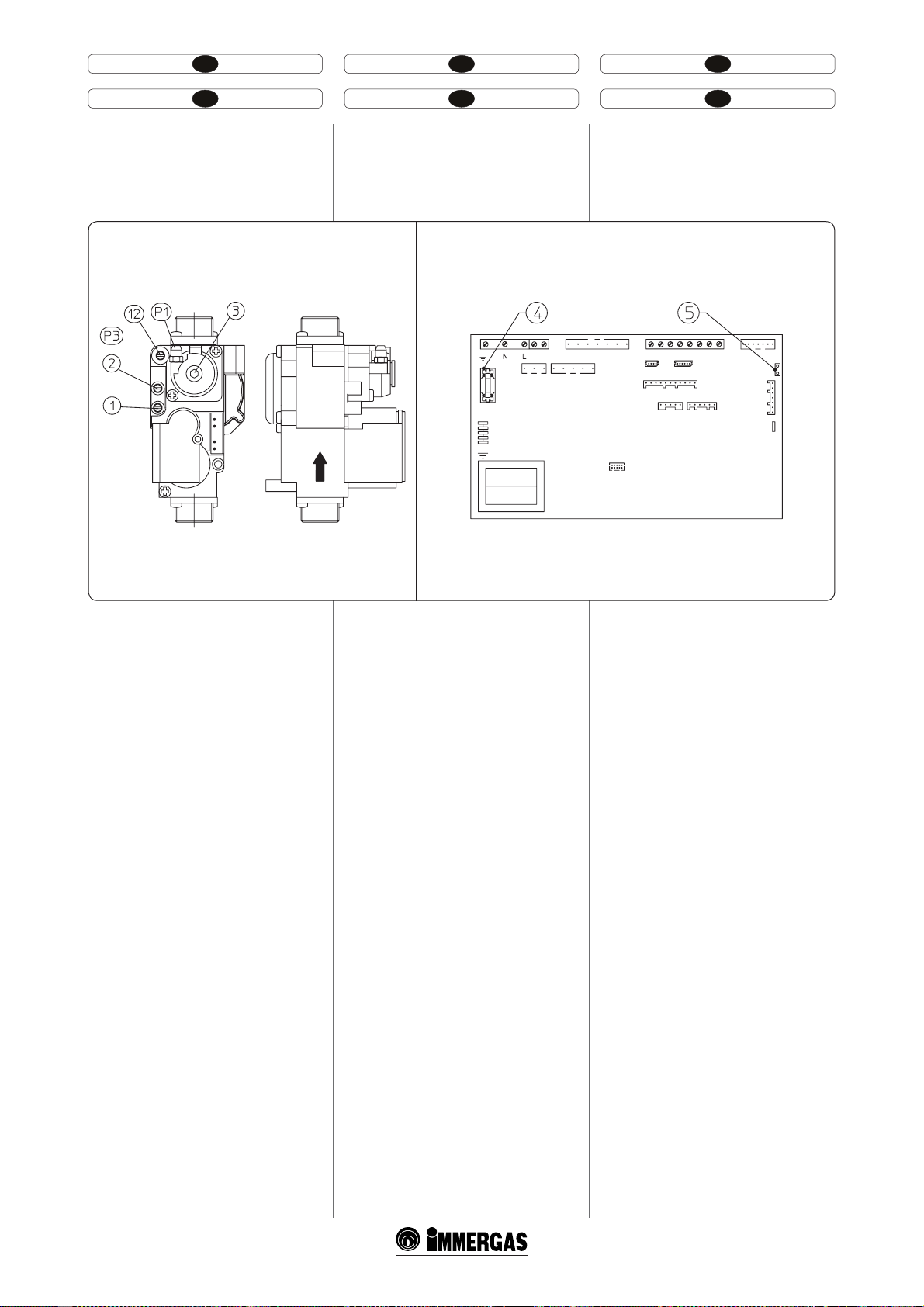
PL CZTR
HU IERO
Zawór Gaz 8115 (Fig. 3-3)
Karta elektroniczna:
Victrix Superior 32 kW X (Fig. 3-4)
8115 Gázszelep (3-3 ábra)
Victrix Superior 32 kW X
elektronikus kártya (3-4. ábra)
Gaz falfı 8115 (Fig. 3-3)
Elektronik kart
Victrix Superior 32 kW X (Fig. 3-4)
Supapă GAZ 8115 (Fig. 3-3)
Placă electronică
Victrix Superior 32 kW X (Fig. 3-4)
Plynový ventil GAS 8115 (Obr. 3-3)
Elektronická karta
Victrix Superior 32 kW X (Obr. 3-4)
SIT 8115 gas valve (Fig. 3-3)
Victrix Superior 32 kW X
circuit board (Fig. 3-4)
Opis (Rys. 3-3 / 3-4):
1 - Pobór ciśnienia - wejście zaworu gazu
2 - Pobór ciśnienia - wyjście zaworu gazu
3 - Śruba regulacyjna O/Set
12 - Regulator natężenia gazu przy wyjściu
4 - Bezpiecznik 3,15AF
5 - Łącznik kontroli prędkości wentylatora
Jelmagyarázat: (3-3 / 3-4 ábra):
1 - Gázszelep bemeneti nyomásmérő pont
2 - Gázszelep kimeneti nyomásmérő pont
3 - O/Set szabályozó csavarok
12 - Kimeneteli gázhozam szabályozója
4 - 3,15AF Olvadó biztosíták
5 - Ventilátor gyorsaságát ellenőrző konektor
Açıklamalar (Şekil 3-3 / 3-4):
1 - Gaz valf giriş basınç tutuşu
2 - Gaz valf çıkış basınç tutuşu
3 - O-Set ayar vidası
12 - Çıkışta gaz aktarım regülatörü
4 - Sigorta 3,15AF
5 - Fan hız kontrol konektörü
Legendă (Fig. 3-3 / 3-4):
1 - Priză presiune intrare valvă gaz
2 - Priză presiune ieşire valvă gaz
3 - Şurub de reglare O/Set
12 - Reglator capacitate gaz la ieşire
4 - Siguranţă 3,15AF
5 - Conector vericare viteză ventilator
Legenda (Obr. 3-3/3-4):
1 - Zásuvka vstupního tlaku plynového ventilu
2 - Zásuvka výstupního tlaku plynového ventilu
3 - Šroub regulace O/Set
12 - Regulátor průtoku plynu na výstupu
4 - Pojistka 3,15AF
5 - Konektor pro kontrolu rychlosti ventilátoru
Key (Fig. 3-3 / 3-4):
1 - Gas valve inlet pressure point
2 - Gas valve outlet pressure point
3 - O/Set adjustment screw
12 - Outlet gas ow adjuster
4 - Line fuse 3,15AF
5 - Fan speed check connector
3-43-3
102
Page 57
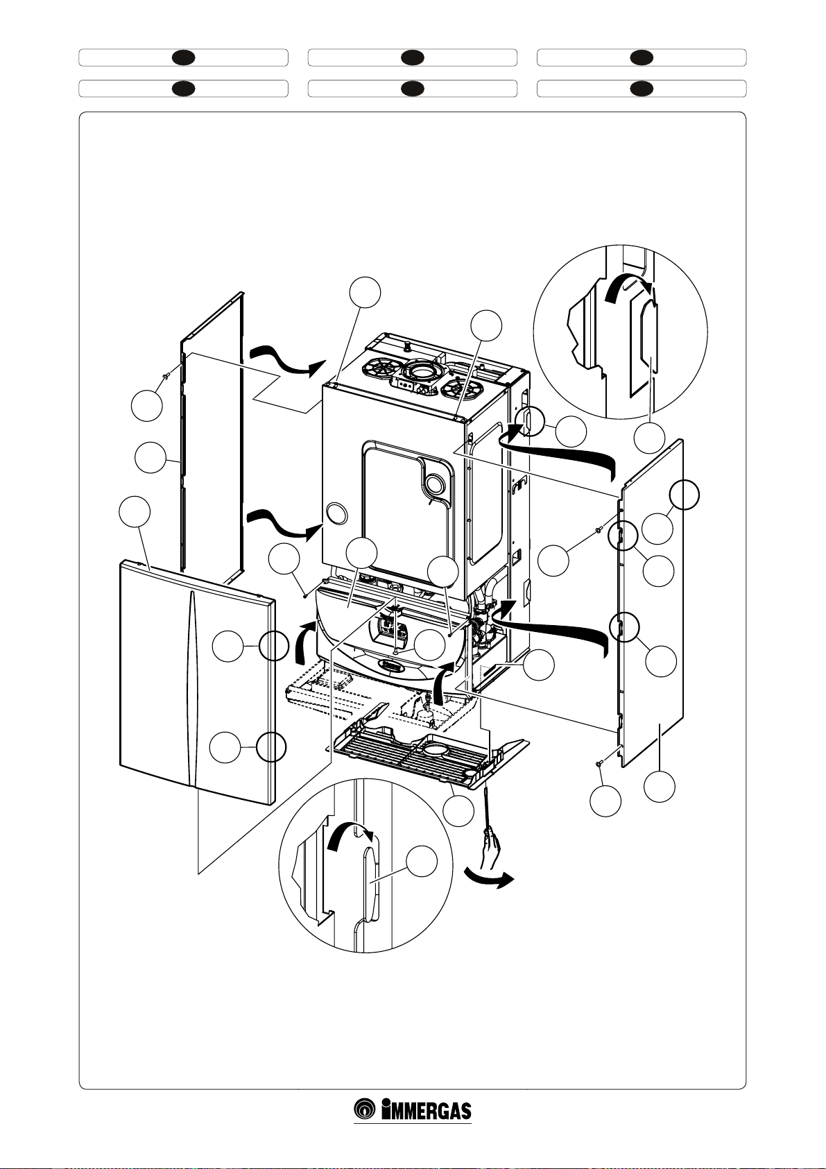
PL CZTR
HU IERO
8
Part. B
4
4
B
9
7
1
B
5
A
6
5
8
A
2
11
A
A
7
10
8
Part. A
3
3-5
103
Page 58

HU IERO
hogy a sarok a helyéről kiakadjon (9) és húzza
maga felé (lásd az ábrát);
- Szerelje le az alsó rácsot (10) kiakasztva a két tokból
(11) behelyezve egy csavarhúzót a rácson bejegyzett
helyre és megemelve, amint azt az ábra mutatja.
3.17 A BERENDEZÉS ÉVES ELLENŐRZÉSE
ÉS KARBANTARTÁSA.
Legalább egy éves időközönként kell a következő
ellenőrzési és karbantartási műveleteket elvégezni.
- A füstoldali hőcserélő tisztítása.
- Takarítsa ki a főégőt.
- Ellenőrizze a begyújtás és a működés szabályosságát.
- Ellenőrizze a forraló megfelelő tárázását használati fázisban (amikor a kazán egy külső
forraló egységhez van csatlakoztatva) és a fűtési
fázisban.
- A készülék vezérlő és szabályozó berendezései
szabályszerű működésének ellenőrzése, különös
tekintettel:
- a kazán elektromos főkapcsolójának
működésére;
- a fűtésszabályozó termosztát működésére;
- a használati víz szabályozási termosztát bea-
vatkozása (amikor a kazán egy külső forraló
egységhez van csatlakoztatva).
- Ellenőrizze a belső berendezés állapotát.
- Ellenőrizni kell a gázhiány esetén működésbe
lépő ionizációs lángőr beavatkozását:
- a reakcióidőnek 10 másodpercnél rövidebbnek
kell lennie.
- Szemrevételezéssel ellenőrizni kell, nincs-e
szivárgás vagy oxidáció a vízcsatlakozásoknál
és kondenzmaradék a zárt kamra blesejében.
- Ellenőrizze a kondenz kiürítési dugó segítségével,
hogy nincsenek anyagmaradékok, amelyek
elzárják a kondenz távozási útját.
- Ellenőrizze kondenzkiürítő szifon tartalmát.
- Szemrevételezéssel ellenőrizze, hogy bizotnsági
vízszelep kiürítése nincs elzáródva.
- Ellenőrizni kell, hogy a fűtési rendszer nyomását
(a kazán nyomásmérőjének állása szerint) nullára csökkentve a tágulási tartály nyomása 1,0
bar legyen.
- Ellenőrizni kell, hogy a fűtési rendszer statikus
víznyomása (hideg, és a töltőcsappal frissen újratöltött rendszerben) 1 és 1,2 bar között legyen.
- Szemrevételezéssel ellenőrizni kell, hogy a
biztonsági és vezérlő berendezések épek és
nincsenek rövidre zárva, különös tekintettel:
- a biztonsági termosztát túlmelegedésre;
- Ellenőrizze az elektromos hálózat tartósságát és
épségét, különös tekintettel:
- az elektromos tápkábelek megfelelő helyen
történő vezetésére;
- esetleges fekete elszíneződésekre és égési
nyomokra.
MEGJ.: a berendezés időszakos karbantartása esetében el kell végezni a hőberendezés ellenőrzését
és karbantartását, amint az érévényes jogszabályok
előírják.
- demontaţi grilajul inferior (10) desprinzându-l
din cele două locaşuri ale acestuia (11) introducând o şurubelniţă în locaşul corespunzător
însemnat pe grilaj şi apăsând ca în gură.
3.17 CONTROL ŞI ÎNTREŢINEREANUALĂ
A APARATULUI.
Cu o periodicitate cel puţin anuală trebuie să e
executate următoarele operaţiuni de control şi
întreţinere.
- Curăţaţi schimbătorul latura gaze arse.
- Curăţaţi arzătorul principal.
- Controlaţi regularitatea pornirii şi funcţionării.
- Vericaţi calibrarea corectă a arzătorului în faza
menajer (când centrala e racordată la o unitate
erbător externă) şi încălzire.
- Vericaţi funcţionarea normală a dispozitivelor
de comandă şi reglarea aparatului şi în special:
- intervenţia întrerupătorului general electric
aşezat pe centrală;
- intervenţia termostatului reglare instalaţie;
- intervenţia termostatului de reglare mena-
jer (când centrala e racordată la o unitate
erbător externă).
- Vericaţi etanşeitatea circuitului de gaz a aparatului şi a instalaţiei interne.
- Vericaţi intervenţia dispozitivului împotriva
lipsei de gaz control acără cu ionizare:
- Controlaţi ca timpul relativ de intervenţie să
e mai mic de 10 secunde.
- Vericaţi vizual absenţa pierderilor de apă şi
oxidările din/pe racorduri şi urme de reziduuri de apă de condensare în interiorul camerei
etanş.
- Vericaţi prin intermediul dopului de evacuare
apă de condensare să nu e reziduuri de material
care să împiedice trecerea apei de condensare.
- Vericaţi conţinutul sifonului de evacuare apă
de condensare.
- Controlaţi vizual ca evacuarea valvei de siguranţ ă
a apei să nu e obturată.
- Vericaţi ca încărcarea vasului de expansiune,
după eliminarea presiunii din instalaţie ducând-o
la zero (citibil pe manometrul centralei) să e 1,0
bari.
- Vericaţi ca presiunea statică a instalaţiei (cu
instalaţie rece şi după ce s-a reîncărcat instalaţia
prin robinetul de reumplere) să e cuprinsă între
1 şi 1,2 bari.
- Vericaţi vizual ca dispozitivele de siguranţă şi
de control, să nu e atinse şi/sau scurtcircuitate
şi în special:
- termostat de siguranţă temperatură;
- Verificaţi păstrarea şi integritatea instalaţiei
electrice şi în special:
- rele de alimentare electrică trebuie să e
aşezate în cabluri de protecţie;
- nu trebuie să e prezente urme de înnegrire
sau arsuri.
N.B.: cu ocazia întreţinerii periodice a aparatului
este necesar să efectuaţi şi controlul şi întreţinerea
instalaţiei termice, conform indicaţiilor normei
în vigoare.
- remove the lower grid (10) removing it from the
two seats (11) by inserting a screwdriver into the
relevant seat marked on the grid and using it as
a lever as represented in the gure.
3.17 YEARLY CONTROL AND MAINTE
NANCE OF THE APPLIANCE.
e following checks and maintenance should be
performed at least once a year.
- Clean the ue side of the heat exchanger.
- Clean the main burner.
- Check correct ignition and functioning.
- Check the correct calibration of the burner in
domestic hot water phase (when the boiler is
connected to an external storage unit) and also
heating.
- Check correct functioning of appliance control
and adjustment devices and in particular:
- the intervention of main electrical switch on
the boiler;
- system control thermostat intervention;
- the domestic hot water adjustment thermostat
intervention (when the boiler is connected to
an external storage unit).
- Check sealing eciency of gas circuit and the
internal system.
- Check intervention of the device against no gas
ionization ame control:
- check that the relative inter vention time is less
than 10 seconds.
- Visually check for water leaks or oxidation from/
on connections and traces of condensate residues
inside the sealed chamber.
- Check, by means of the condensate drain cap,
that there are no residuals of material blocking
the ow of condensate.
- Check contents of the condensate drain trap.
- Visually check that the water safety drain valve
is not blocked.
- Check that, aer discharging system pressure and
bringing it to zero (read on boiler manometer),
the expansion vessel charge is at 1.0 bar.
- Check that the system static pressure (with system cold and aer relling the system by means
of the ller cock) is between 1 and 1.2 bar.
- Check visually that the safety and control devices
have not been tampered with and/or shorted, in
particular:
- temperature safety thermostat;
- Check the condition and integrity of the electrical system and in particular:
- electrical power cables must be inside the
whipping;
- there must be no traces of blackening or
burning.
N.B.: on occasion of periodical maintenance of the
appliance it is appropriate also to check and perform
maintenance on the heating system, in compliance
with that indicated by the regulations in force.
105
Page 59

HU
3.18 VÁLTOZTATHATÓ HŐTELJESÍTMÉNY.
Megj.: a táblázatban feltüntetett nyomásértékek a gázszelep vége és a zárt
égéstér nyomáskülönbségére vonatkoznak (lásd 13 ás 14 méréspróbák, 1-25
ábra). A beszabályozást tized mm-es vagy Pascal dierenciál nyomásmérővel
kell elvégezni.A táblázatban feltüntetett teljesítményadatokat 0,5 m hosszúságú égéslevegő-füstcsővel állapították meg. A gázhozamok a legalacsonyabb fűtőértékű gázra vonatkoznak 15°C hőmérsékletnél, 1013 mbar
légköri nyomáson. Az égőnél mért nyomásértékek 15°C hőmérsékletű gázra
vonatkoznak.
METAN (G20) BUTAN (G30) PROPAN (G31) G25.1
TERM.
TELJESÍ.
(kW) (kcal/h) (m
32,0 27520 3,46 2,45 25,0 2,58 2,68 27,3 2,54 3,35 34,2 4,02 4,25 43,3
31,0 26660 3,35 2,32 23,6 2,50 2,54 25,9 2,46 3,16 32,2 3,89 4,02 40,9
30,0 25800 3,24 2,19 22,3 2,42 2,39 24,4 2,38 2,97 30,3 3,77 3,79 38,6
29,0 24940 3,14 2,06 21,0 2,34 2,26 23,0 2,30 2,79 28,5 3,65 3,56 36,3
28,0 24080 3,03 1,94 19,8 2,26 2,12 21,7 2,22 2,62 26,7 3,52 3,35 34,1
27,0 23220 2,92 1,82 18,5 2,18 1,99 20,3 2,14 2,45 24,9 3,40 3,14 32,0
26,3 22603 2,84 1,73 17,7 2,12 1,90 19,4 2,09 2,33 23,7 3,31 2,99 30,5
25,0 21500 2,71 1,59 16,2 2,02 1,74 17,8 1,99 2,12 21,6 3,15 2,74 27,9
24,0 20640 2,60 1,48 15,1 1,94 1,63 16,6 1,91 1,97 20,1 3,02 2,54 25,9
23,0 19780 2,49 1,38 14,0 1,86 1,51 15,4 1,83 1,82 18,6 2,90 2,36 24,0
22,0 18920 2,39 1,27 13,0 1,78 1,40 14,3 1,75 1,68 17,1 2,77 2,18 22,2
21,0 18060 2,28 1,17 12,0 1,70 1,29 13,2 1,67 1,54 15,7 2,65 2,01 20,5
20,0 17200 2,17 1,08 11,0 1,62 1,19 12,1 1,59 1,41 14,4 2,52 1,84 18,8
19,0 16340 2,06 0,99 10,1 1,54 1,09 11,1 1,51 1,28 13,1 2,40 1,68 17,1
18,0 15480 1,95 0,90 9,2 1,46 0,99 10,1 1,43 1,16 11,9 2,27 1,52 15,5
17,0 14620 1,85 0,82 8,3 1,38 0,90 9,2 1,36 1,05 10,7 2,15 1,38 14,0
16,0 13760 1,74 0,73 7,5 1,30 0,81 8,2 1,28 0,94 9,6 2,02 1,24 12,6
15,0 12900 1,63 0,66 6,7 1,22 0,72 7,4 1,20 0,84 8,5 1,90 1,10 11,2
14,0 12040 1,52 0,58 5,9 1,14 0,64 6,6 1,12 0,74 7,5 1,77 0,97 9,9
13,0 11180 1,41 0,51 5,2 1,06 0,56 5,8 1,04 0,65 6,6 1,64 0,85 8,7
12,0 10320 1,31 0,45 4,6 0,97 0,49 5,0 0,96 0,56 5,7 1,52 0,73 7,5
11,0 9460 1,20 0,38 3,9 0,89 0,42 4,3 0,88 0,48 4,9 1,39 0,62 6,3
10,0 8600 1,09 0,32 3,3 0,81 0,36 3,6 0,80 0,40 4,1 1,27 0,52 5,3
9,0 7740 0,98 0,27 2,7 0,73 0,29 3,0 0,72 0,33 3,4 1,14 0,42 4,3
8,0 6880 0,87 0,22 2,2 0,65 0,24 2,4 0,64 0,27 2,8 1,01 0,33 3,4
7,0 6020 0,76 0,17 1,7 0,57 0,18 1,8 0,56 0,21 2,2 0,89 0,25 2,5
6,4 5504 0,70 0,14 1,4 0,52 0,15 1,5 0,51 0,18 1,8 0,81 0,20 2,0
TERM.
TELJESÍ
ÉGŐ GÁZHO-
ZAMA
3
/h) (mbar) (mm H2O) (kg/h) (mbar) (mm H2O) (kg/h) (mbar) (mm H2O) (m3/h) (mbar) (mm H2O)
GÁZFUVÓKA
NYOMÁSA
ÉGŐ GÁZHO-
ZAMA
GÁZFUVÓKA
NYOMÁSA
ÉGŐ GÁZHO-
ZAMA
GÁZFUVÓKA
NYOMÁSA
ÉGŐ GÁZHO-
ZAMA
GÁZFUVÓKA
NYOMÁSA
109
Page 60
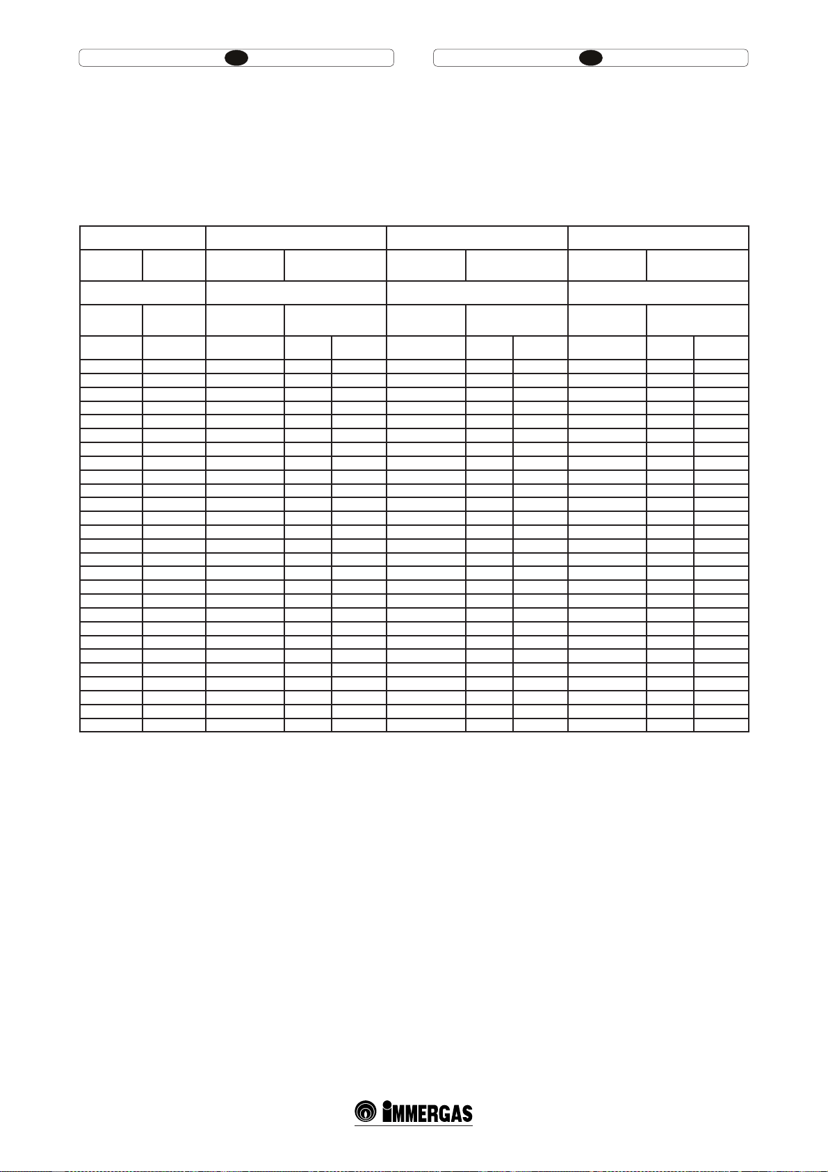
RO IE
3.18 PUTERE TERMICĂ VARIABILĂ.
N.B.: presiunile indicate în tabel reprezintă diferenţele de presiuni existente
la capetele de venturilor de amestecare şi măsurabile de priza de presiune
prezente în partea superioară a camerei etanş (vezi probă presiune 13 şi 14
Fig. 1-25). Reglările sunt efectuate cu manometru diferenţial digital având
scara în zecimal de mm sau Pascal. Datele de putere din tabel au fost luate
cu tubul de aspirare-evacuare de lungime 0,5m. Capacităţile gaz se referă la
puterea calorică inferioară temperaturii de15 C şi la presiunea de 1013 mbari.
Presiunile arzătorului se referă la utilizarea de gaz la temperatura de 15 C.
3.18 VARIABLE HEAT POWER.
N.B.: the pressures indicated in the table represent the dierences of pressures
at the ends of the Venturi mixer and can be measured from the pressure point
in the upper part of the sealed chamber (see pressure test 13 and 14 Fig. 1-25).
e adjustments must be performed using a digital dierential manometer
with a scale in tenths of mm or Pascal. e power data in the table has been
obtained with intake-exhaust pipe measuring 0.5 m in length. Gas ow rates
refer to heating power below a temperature of 15°C and at a pressure of 1013
mbar. Burner pressure values refer to use of gas at 15°C.
METAN (G20) BUTAN (G30) PROPAN (G31)
PUTERE
TERMICĂ
PUTERE
TERMICĂ
CAPACITATE GAZ
ARZĂTOR
ARZĂTOR PUTERE
DUZE
CAPACITATE GAZ
ARZĂTOR
ARZĂTOR PUTERE
DUZE
CAPACITATE GAZ
ARZĂTOR
ARZĂTOR PUTERE
DUZE
METHANE (G20) BUTANE (G30) PROPANE (G31)
HEATING
POWER
HEATING
POWER
BURNER GAS
FLOW RATE
PRESS. BURNER
NOZZLES
BURNER GAS
FLOW RATE
PRESS. BURNER
NOZZLES
BURNER GAS
FLOW RATE
PRESS. BURNER
NOZZLES
(kW) (kcal/h) (m3/h) (mbar) (mm H2O) (kg/h) (mbar) (mm H2O) (kg/h) (mbar) (mm H2O)
32,0 27520 3,46 2,45 25,0 2,58 2,68 27,3 2,54 3,35 34,2
31,0 26660 3,35 2,32 23,6 2,50 2,54 25,9 2,46 3,16 32,2
30,0 25800 3,24 2,19 22,3 2,42 2,39 24,4 2,38 2,97 30,3
29,0 24940 3,14 2,06 21,0 2,34 2,26 23,0 2,30 2,79 28,5
28,0 24080 3,03 1,94 19,8 2,26 2,12 21,7 2,22 2,62 26,7
27,0 23220 2,92 1,82 18,5 2,18 1,99 20,3 2,14 2,45 24,9
26,3 22603 2,84 1,73 17,7 2,12 1,90 19,4 2,09 2,33 23,7
25,0 21500 2,71 1,59 16,2 2,02 1,74 17,8 1,99 2,12 21,6
24,0 20640 2,60 1,48 15,1 1,94 1,63 16,6 1,91 1,97 20,1
23,0 19780 2,49 1,38 14,0 1,86 1,51 15,4 1,83 1,82 18,6
22,0 18920 2,39 1,27 13,0 1,78 1,40 14,3 1,75 1,68 17,1
21,0 18060 2,28 1,17 12,0 1,70 1,29 13,2 1,67 1,54 15,7
20,0 17200 2,17 1,08 11,0 1,62 1,19 12,1 1,59 1,41 14,4
19,0 16340 2,06 0,99 10,1 1,54 1,09 11,1 1,51 1,28 13,1
18,0 15480 1,95 0,90 9,2 1,46 0,99 10,1 1,43 1,16 11,9
17,0 14620 1,85 0,82 8,3 1,38 0,90 9,2 1,36 1,05 10,7
16,0 13760 1,74 0,73 7,5 1,30 0,81 8,2 1,28 0,94 9,6
15,0 12900 1,63 0,66 6,7 1,22 0,72 7,4 1,20 0,84 8,5
14,0 12040 1,52 0,58 5,9 1,14 0,64 6,6 1,12 0,74 7,5
13,0 11180 1,41 0,51 5,2 1,06 0,56 5,8 1,04 0,65 6,6
12,0 10320 1,31 0,45 4,6 0,97 0,49 5,0 0,96 0,56 5,7
11,0 9460 1,20 0,38 3,9 0,89 0,42 4,3 0,88 0,48 4,9
10,0 8600 1,09 0,32 3,3 0,81 0,36 3,6 0,80 0,40 4,1
9,0 7740 0,98 0,27 2,7 0,73 0,29 3,0 0,72 0,33 3,4
8,0 6880 0,87 0,22 2,2 0,65 0,24 2,4 0,64 0,27 2,8
7,0 6020 0,76 0,17 1,7 0,57 0,18 1,8 0,56 0,21 2,2
6,4 5504 0,70 0,14 1,4 0,52 0,15 1,5 0,51 0,18 1,8
110
Page 61

CZ HU
3.19 TECHNICKÉ ÚDAJE 3.19 MŰSZAKI ADATOK.
Jmenovitá tepelná kapacita Névleges hőteljesítmény
Minimální tepelná kapacita Minimális hőteljesítmény (hasznos)
Jmenovitý tepelný výkon (užitný) Névleges hőteljesítmény (hasznos)
Minimální tepelný výkon (užitný) Minimális hőteljesítmény (hasznos)
Užitný tepelný výkon 80/60 Jmen./Min. 80/60 Névl./Perc hasznos hőteljesítmény
Užitný tepelný výkon 50/30 Jmen./Min. 50/30 Névl./Perc hasznos hőteljesítmény
Užitný tepelný výkon 40/30 Jmen./Min. 40/30 Névl./Perc hasznos hőteljesítmény
Tepelné ztráty na plášti s hořákem Zap/Vyp (80-60°C) Hővesztesség a köpenyen, forralóval O/On (80-60°C)
Tepelné ztráty v komíně s hořákem Zap/Vyp (80-60°C) Hővesztesség a kéményben, forralóval O/On (80-60°C)
Max. provozní tlak ve vytápěcím okruhu Fűtéshálózat működésének max. nyomása
Max. provozní teplota ve vytápěcím okruhu Fűtéshálózat működésének max. hőmérséklete
Nastavitelná teplota vytápění Poz. 1 Fűtés szabályozható hőmérséklete, 1-es poz.
Nastavitelná teplota vytápění Poz. 2 Fűtés szabályozható hőmérséklete, 2-es poz.
Celkový objem expanzní nádoby Berendezés kiterjesztési tartályának teljes térfogata
Tlak v expanzní nádobě Kiterjesztési tartály újratöltése
Objem vody v kotli Generátor víztartalma
Využitelný výtlak při průtoku 1000l/h 1000/h hozam rendelkezésre álló túlsúly
* Měrný průtok “D” UB Immergas 80 l podle EN 625 * Specikus hozam “D” UB Immergas 80 l másodperc EN 625
* Měrný průtok “D” UB Immergas 105 l podle EN 625 * Specikus hozam “D” UB Immergas 105 l másodperc EN 625
* Měrný průtok “D” UB Immergas 120 l podle EN 625 * Specikus hozam “D” UB Immergas 120 l másodperc EN 625
* Měrný průtok “D” UB Immergas 200 l podle EN 625 * Specikus hozam “D” UB Immergas 200 l másodperc EN 625
Výkon při stálém odběru s UB Immergas (∆T 30°C) Folyamatos vételezési képesség UB Immergas (∆T 30°C)
Hmotnost plného kotle Tele kazán súlya
Hmotnost prázdného kotle Üres kazán súlya
Elektrická přípojka Elektromos csatlakozás
Jmenovitý příkon Névleges felvétel
Instalovaný elektrický výkon Beszerelt elektromos potencia
Příkon oběhového čerpadla Keringető által felvett potencia
Příkon ventilátoru Ventilátor által felvett potencia
Ochrana elektrického zařízení přístroje Berendezés elektromos védelme
Maximální teplota odváděného plynu Max. füstgáz hőmérséklet
Třída NOX NOX kategória
Vážené NOX Mért NOX
Vážené CO Mért CO
Cihaz türü Berendezés típusa
Kategorie Kategória
kW (kcal/h) 32,7 (28082)
kW (kcal/h) 6,6 (5674)
kW (kcal/h) 32,0 (27520)
kW (kcal/h) 6,4 (5504)
% 98,0 / 97,0
% 104,7 / 107,0
% 105,7 / 107,0
% 0,46 / 0,60
% 0,03 / 2,00
bar 3
°C 90
°C 25 - 85
°C 25 - 50
l 8,0
bar 1
l 2,8
kPa (m H2O) 26,48 (2,7)
l/min 21,8
l/min 25,1
l/min 26,6
l/min 37,2
l/min 15,3
kg 50,3
kg 47,5
V/Hz 230/50
A 0,79
W 175
W95
W26
- IPX5D
°C
-5
mg/kWh 30
mg/kWh 17
C13 / C23 / C33 / C43 / C53 /
C83 / B23 / B33
II2H3P / II2HS3B/P
- Hodnoty teploty spalin odpovídají vstupní teplotě vzduchu 15°C a
náběhové teplotě 50°.
- Hodnoty týkající se výkonu teplé užitkové vody se vztahují k dynamickému
vstupnímu tlaku 2 bary a vstupní teplotě 15 °C; hodnoty jsou zjišťovány
ihned po výstupu z kotle, přičemž k dosažení uvedených hodnot je nutné
smíchání se studenou vodou.
- Maximální hluk vydávaný při chodu kotle je < 55 dBA. Měření hladiny
hluku probíhá v poloakusticky mrtvé komoře u kotle zapnutého na maximální tepelný výkon, s kouřovým systémem prodlouženým v souladu
s normami výrobku.
- * Měrný průtok “D”: průtok teplé užitkové vody odpovídající průměrnému
zvýšení teploty o 30 K, který kotel může vyvinout ve dvou po sobě následujících odběrech.
- A füsthőmérséklet értékekek 15°C –os bemeneteli levegő hőmérsékletre
és 50° C-os kimeneteli levegőhőmérsékletre vonatkoznak.
- A használati meleg vízszolgáltatás adatai 2 bar-os bemeneteli dinamikus
nyomásra vonatkoznak és 15°C-os bemeneteli hőmérsékletre ; az adatokat
közvetlenül a kazán kimenetelénél veszik fel tekintettel arra, hogy az adott
adatok felvételére hideg vizzel való keveredésre van szükség.
- A kazán maximális zajkibocsájtása < 55dBA. A hangpotencia mértéke
a szemianekoikus kamra próbáira vonatkoznak a maximális hozammal
működő kazánnal, a füstkéményeknek a gyártási előírásoknak megfelelő
kiterjedésével.
- * “D” specikus hozam: a meleg víz hozama megfelel a 30 K átlagos
környezeti hőmérséklet növekedésnek, amelyet a kazán két egymás utáni
méréskor képes felvenni.
- Muszaki adatok: az adattábla tartalmazza.
- Minoségtanúsítás: 2/1984 (III.1.o.) BKM-IPM rendelet szerint a készülék
a kezelési útmutatónak megfelel.
- Megfeleloségi nyilatkozat: A készülék a 90/396/CEE és a 92/42/CEE EU
direktíváknak megfelel, jogosult a CE jel használatára.
- A termék a 84/2001 (V.30.) Kormányrendelet szerint a rendelkezésre álló,
Magyarországra kiterjesztett HU jellel ellátott bevizsgálási engedélyek
alapján Magyarországon forgalmazható.
112
Page 62

RO IE
3.19 DATE TEHNICE . 3.19 TECHNICAL DATA.
Capacitate termică nominală Nominal heating power
Capacitate termică minimă Minimum heating power
Putere termică nominală (utilă) Nominal heating power (useful)
Putere termică minimă (utilă) Minimum heating power (useful)
Randament termic util 80/60 Nom./Min. Useful thermal eciency 80/60 Nom. /Min.
Randament termic util 50/30 Nom./Min. Useful thermal eciency 50/30 Nom. /Min.
Randament termic util 40/30 Nom./Min. Useful thermal eciency 40/30 Nom. /Min.
Pierdere de căldură la înveliş cu arzătorul O/On (80-60°C) Heat loss at casing with burner O/On (80-60°C)
Pierdere de căldură la cămin cu arzătorul O/On (80-60°C) Heat loss at ue with burner O/On (80-60°C)
Presiune max. de exerciţiu circuit încălzire Heating circuit max. working pressure
Temperatură max. de exerciţiu circuit încălzire Heating circuit max. working temperature
Temperatura reglabilă încălzire Pos 1 Adjustable heating temperature Pos 1
Temperatura reglabilă încălzire Pos 2 Adjustable heating temperature Pos 2
Vas de expansiune instalaţie volum total Total volume system heating expansion vessel
Preîncărcare vas de expansiune Expansion vessel pre-charge
Conţinut de apă a generatorului Generator water capacity
Nivel lichid disponibil cu capacitate 1000/h Total head available with capacity of 1000/h
* Capacitate specică “D” UB Immergas 80 l conform EN 625 *“D” UB Immergas 80 l ow rate according to EN 625
* Capacitate specică “D” UB Immergas 105 l conform EN 625 *“D” UB Immergas 105 l ow rate according to EN 625
*Capacitate specică “D” UB Immergas 120 l conform EN 625 *“D” UB Immergas 120 l ow rate according to EN 625
*Capacitate specică “D” UB Immergas 200 l conform EN 625 *“D” UB Immergas 200 l ow rate according to EN 625
Capacitate de preluare continuă cu UB Immergas (∆T 30°C) Continuous withdrawal capacity with UB Immergas (∆T 30°C)
Greutate centrală plină Weight of full boiler
Greutate centrală goală Weight of empty boiler
Racord electric Electric attachment
Absorbţie nominală Nominal absorption
Putere electrică instalată Installed electric power
Putere absorbită de circulator Power absorbed by circulation pump
Putere absorbită de ventilator Power absorbed by fan
Protecţie instalaţie electrică aparat Equipment electrical system protection
Temperatură max gaz de evacuare Flue gas max. temperature
Clasă dw NOX NOX Class
NOX ponderat Weighted NOX
CO ponderat Weighted CO
Tip aparat Type of appliance
Categorie Category
kW (kcal/h) 32,7 (28082)
kW (kcal/h) 6,6 (5674)
kW (kcal/h) 32,0 (27520)
kW (kcal/h) 6,4 (5504)
% 98,0 / 97,0
% 104,7 / 107,0
% 105,7 / 107,0
% 0,46 / 0,60
% 0,03 / 2,00
bar 3
°C 90
°C 25 - 85
°C 25 - 50
l 8,0
bar 1
l 2,8
kPa (m H2O) 26,48 (2,7)
l/min 21,8
l/min 25,1
l/min 26,6
l/min 37,2
l/min 15,3
kg 50,3
kg 47,5
V/Hz 230/50
A 0,79
W 175
W95
W26
- IPX5D
°C
-5
mg/kWh 30
mg/kWh 17
C13 / C23 / C33 / C43 / C53 /
C83 / B23 / B33
II2H3B/P
- Valorile de temperatură a gazelor arse se referă la temperatura aerului la
intrare de 150 C şi temperatura de tur de 50° C.
- Datele referitoare la producerea de apă caldă menajeră se referă la o
presiune de intrare dinamică de 2 bari şi la o temperatură de intrare de
15 0C şi valorile sunt relevate imediat la ieşirea cazanului considerând că
pentru a obţine datele declarate este necesară amestecarea cu apă rece.
- Puterea maximă sonoră emisă în timpul funcţionării centralei este <
55dBA. Măsura de putere sonoră se referă la probe cu cameră izolată
fonic cu centrala în funcţiune la capacitate termică maximă, cu extinderea
dispozitivelor de eliminare fumuri conform normelor produsului.
- * Putere specică „D”: puterea apei calde menajere corespunzătoare unei
măriri medii de temperatură de 30K, pe care centrala o poate furniza în
două prelevări succesive.
- Fume temperature values refer to an air inlet temperature of 15°C and
delivery temperature of 50°C.
- e data relevant to domestic hot water performance refer to a dynamic
inlet pressure of 2 bar and an inlet temperature of 15°C; the values are
measured directly at the boiler outlet considering that to obtain the data
declared mixing with cold water is necessary. .
- e max. sound level emitted during boiler operation is < 55dBA. e
sound level value is referred to semianechoic chamber tests with boiler
operating at max. heat output, with extension of fume exhaust system
according to product standards.
- * Specic capacity “D”: domestic hot water ow rate corresponding to an
average increase of 30K, which the boiler can supply in two successive
withdrawals.
113
Page 63
HU IERO
3.20 AZ ÜZEMANYAGFOGYASZTÁS PARAMÉTEREI.
G20 G30 G31 G25.1
Ellátási nyomás mbar (mm H
Gázfúvóka átmérője mm 9,30 5,40 5,40 8,50
Füsttömeg hozama névleges teljesítményen kg/h 52 46 53 60
Füsttömeg hozama minimális teljesítményen kg/h 11 10 11 12
CO
a Q. Nom./Min. % 9,40 / 9,05 12,30 / 11,70 10,40 / 10,10 10,70 / 10,45
2
CO a 0% di O
NO
a 0% di O2 a Q. Nom./Min. ppm 24 / 11 106 / 22 25 / 14 20 / 8
X
a Q. Nom./Min. ppm 145 / 2 560 / 3 160 / 2 150 / 2
2
Füsthőmérséklet névleges teljesítményen °C 68 76 68 67
Füsthőmérséklet minimális teljesítményen °C 61 67 61 60
O) 20 (204) 29 (296) 37 (377) 25 (255)
2
3.20 PARAMETRII COMBUSTIEI.
G20 G30 G31
Presiune de alimentare mbar (mm H
O) 20 (204) 29 (296) 37 (377)
2
Diametru duză gaz mm 9,30 5,40 5,40
Capacitate în masă a gazelor arse cu putere nominală kg/h 52 46 53
Capacitate în masă a gazelor arse cu putere minimă kg/h 11 10 11
CO
la Q. Nom./Min. % 9,40 / 9,05 12,30 / 11,70 10,40 / 10,10
2
CO la 0% de O
NO
la 0% de O2 a Q. Nom./Min. ppm 24 / 11 106 / 22 25 / 14
X
a Q. Nom./Min. ppm 145 / 2 560 / 3 160 / 2
2
Temperatură gaze arse la putere nominală °C 68 76 68
Temperatură gaze arse la putere minimă °C 61 67 61
3.20 COMBUSTION PARAMETERS.
G20 G30 G31
Supply pressure mbar (mm H
O) 20 (204) 29 (296) 37 (377)
2
Gas nozzle diameter mm 9,30 5,40 5,40
Mass ow of fumes at nominal power kg/h 52 46 53
Mass ow of fumes at min. power kg/h 11 10 11
CO
at Q. Nom./Min. % 9,40 / 9,05 12,30 / 11,70 10,40 / 10,10
2
CO with 0% di O
NOX with 0% di O
at Q. Nom./Min. ppm 145 / 2 560 / 3 160 / 2
2
at Q. Nom./Min. ppm 24 / 11 106 / 22 25 / 14
2
Temperature of fumes at nominal power °C 68 76 68
Temperature of fumes at minimum power °C 61 67 61
115
Page 64
RO
LIVRET APARAT
1)
(1) APARAT INDIVIDUAL
DESTINAT: - încălzirii
- producerii apei calde menajere
- alte destinaţii*
* descriere ( aparat consumator de combustibili
gazoși folosit pentru gătit, refrigerare, iluminare, spălare etc.) ___________________________________
IDENTIFICARE UTILIZATOR FINAL:
Nume / Denumire ___________________________________________
Adresa ____________________________________________________
Bloc ______ Scară ______ Etaj _____ Locuinţă individuală __________
2) IDENTIFICARE AGENT ECONOMIC, autorizat de ISCIR, care are în evidenţă
şi supraveghere aparatul (care a editat sau / şi completat livretul):
DENUMIRE agent economic: ______________________________________________________________
Nr. de înregistrare la Registrul Comerţului ____________________; Cod scal ________________________
ADRESĂ: _____________________________________________________ Telefon __________________
AUTORIZAŢIE ISCIR NR. ____________ / ________________
VALABILITATE autorizaţie ______________________________
DATA luării în evidenţă ________________ SEMNĂTURA ___________________
(3) PERSONAL AUTORIZAT AL PRESTATORULUI DE SPECIALITATE
2)
Nume _____________________________________________ Semnătura ________________
UTILIZATOR FINAL
2)
________________________________
Nume _____________________________________________ Semnătura _________________ Data ____________
1)
Livretul se va modica ori de câte ori se schimba utilizatorul nal sau agentul economic autorizat de ISCIR în a cărui evidenţă este înscris.
2)
Prin semnarea acestui document utilizatorul nal îşi asumă obligaţia efectuării vericărilor tehnice periodice ale aparatului, iar prestatorul de specialitate
garantează efectuarea instructajului privind folosirea aparatului în condiţii de siguranţă.
(4) CARACTERISTICILE APARATULUI ŞI ALE INSTALAŢIEI ÎN CARE ACESTA ESTE INCORPORAT
(4.1) APARAT CONSUMATOR DE COMBUSTIBIL GAZOS
Fabricant IMMERGAS S.p.A. - Italia
Model __________________________________________ Seria matricolă ________________________
Tip de instalare mural
de pardoseală
Fluid de lucru apă aer
Arzător cu aer insuat atmosferic
Combustibil ___________________________________________________________________________
Evacuare gaze de ardere naturală
forţată
Puterea nominală (kW) ____________________________
Randament util la putere nominală (%)________________
Nivel de certicare (CE, CS, omologat ISCIR) __________
(4.2) EVACUARE GAZE DE ARDERE
Coş individual coş colectiv tubulatură de evacuare
(4.3) REGLARE AUTOMATĂ (cu comandă locală sau de la distanţă)
_________________________________________________________________
Fabricantul dispozitivului de comandă ___________________________________
Model ____________________________________________________________
Programator zilnic de 24 ore cu n = ___________________ nivele de temperatură
Programator săptămânal (1) ____________ lunar (1) ______________
(4.4) ROBINEŢI TERMOSTATAŢI
Procentaj de existenţă la “consumatorii direcţi” *
)
ai aparatului _________ (%)
(4.5) SISTEM DE REGLARE, COMANDĂ ŞI PROTECŢIE
Descrierea sistemului ____________________________________________________________________________
______________________________________________________________________________________________
______________________________________________________________________________________________
*) “consumatori direcţi” pot corpuri de încălzire (calorifere, boilere,preparatoare de apă caldă şi similare).
116
Page 65
RO
(4.6) SISTEME DE VENTILARE ŞI ASIGURARE AER PROASPĂT
în localul în care este instalat aparatul
Alimentare cu aer directă
Suprafaţa prizei de aer proaspăt neobturabile: cm2_________
(minim 6 cm
Ventilarea camerei
Alte date despre ventilare_____________________________________________________________
(5) REZULTATE LA PRIMA PUNERE ÎN FUNCŢIUNE ŞI LA VERIFICĂRILE TEHNICE PERIODICE,
2
x kW, nu mai mică de 100 cm2)
da nu
EFECTUATE DE AGENTUL ECONOMIC AUTORIZAT DE ISCIR
debit în m3/h __________________________
indirectă
Data efectuării
Temperatură gaze (°C)
Temperatură ambiantă (°C)
(%)
O
2
(%)
CO
2
CO (%)
Pierderi (%)
Randament la sarcină nominală (%)
Starea de etanșeitate
1)
Starea tubulaturii / sistemului de evacuare gaze arse
Vericarea dispozitivelor de reglare
Vericare protecţii
2)
Vericare sisteme de aerisire și ventilare
2)
2)
Semnătură
1)
indică B = bună; M = mediu; S = slabă;
2)
indică P = pozitivă; N = negativă
Observaţii la întreţinere şi vericarea tehnică periodică:
_____________________________________________________________________________________________
_____________________________________________________________________________________________
_____________________________________________________________________________________________
Intervenţii efectuate la întreţinere / service
Data
Referitor la componentele
la care s-au făcut intervenţii
Observaţii (felul lucrării)
Semnătură personal
autorizat
Immergas S.p.A.
42041 Brescello (RE), Italia
www.immergas.com
Immergas România s.r.l.
B-dul Unirii nr. 80, Bloc J1, sector 3
Bucureşti, România
E-mail: o[email protected]
www.immergas.ro
117
Page 66

is instruction booklet is made of
ecological paper
www.immergas.com
Cod. 1.025785 Rev. 15.026417/000 - 02/08
 Loading...