

Immergas Victrix Pro 80 2ErP, Victrix Pro 100 2ErP, Victrix Pro 120 2ErP Instruction And Warning Book
Page 1
Instruction and
*1.041665ENG*
warning book
IE
VICTRIX PRO
80 - 100 - 120 2 ErP
Page 2

Page 3

Dear Customer,
Our compliments for having chosen a top-quality Immergas product, able to assure well-being and safety for a long period of time. As an Immergas customer
you can also count on a qualied aer-sales service, prepared and updated to guarantee constant eciency of your boiler. Read the following pages carefully: you
will be able to draw useful suggestions regarding the correct use of the appliance, the respect of which, will conrm your satisfaction for the Immergas product.
For assistance and scheduled maintenance contact Authorised Immergas Aer-Sales centres: they have original spare parts and are specically trained directly
by the manufacturer.
General recommendations
All Immergas products are protected with suitable transport packaging.
e material must be stored in dry environments protected against bad weather.
e instruction book is an integral and essential part of the product and must be consigned to the new user also in the case of transfer or succession of ownership.
It must be stored with care and consulted carefully, as all of the warnings provide important safety indications for installation, use and maintenance stages.
is instructions manual provides technical information for installing Immergas boilers. As for the other issues related to boiler installation (e.g. safety in the work
site, environment protection, injury prevention), it is necessary to comply with the provisions specied in the regulations in force and principles of good practice.
In compliance with legislation in force, the systems must be designed by qualied professionals, within the dimensional limits established by the Law. Installation
and maintenance must be performed in compliance with the regulations in force, according to the manufacturer's instructions and by professionally qualied
sta, intending sta with specic technical skills in the plant sector, as envisioned by the Law.
Improper installation or assembly of the Immergas appliance and/or components, accessories, kit and devices can cause unexpected problems to people, animals
and objects. Read the instructions provided with the product carefully to ensure a proper installation.
Maintenance must be carried out by skilled technical sta. e Immergas Authorised Aer-sales Service represents a guarantee of qualications and
professionalism.
e appliance must only be destined for the use for which it has been expressly declared. Any other use will be considered improper and therefore potentially
dangerous.
If errors occur during installation, operation and maintenance, due to non compliance with technical laws in force, standards or instructions contained in this
book (or however supplied by the manufacturer), the manufacturer is excluded from any contractual and extra-contractual liability for any damages and the
appliance warranty is invalidated.
e company IMMERGAS S.p.A., with registered oce in via Cisa Ligure 95 42041 Brescello (RE), declares that the design, manufacturing and aer-sales
assistance processes comply with the requirements of standard UNI EN ISO 9001:2015.
For further details on the product CE marking, request a copy of the Declaration of Conformity from the manufacturer, specifying the appliance model
and the language of the country.
Immergas S.p.A. declines all liability due to printing or transcription errors, reserving the right to make any modications to its technical and commercial
documents without prior notice.
Page 4

INDEX
USER page INSTALLER page MAINTENANCE TECHNICIAN page
1 Boiler installation .......................................5
1.1 Installation recommendations. ................. 5
1.2 Position of the appliances. ......................... 5
1.3 Aeration and Ventilation of the installation
rooms. ........................................................... 6
1.4 Outdoor installation. ..................................6
1.5 Anti-freeze protection. ...............................6
1.6 Main dimensions. ......................................7
1.7 Gas connection. ..........................................7
1.8 Hydraulic connection. ................................7
1.9 Electric connection. ....................................8
1.10 Optional boiler controllers. ......................9
1.11 External temperature probe. ..................... 9
1.12 Immergas ue systems. ............................10
1.13 Tables of equivalent length factors. ........11
1.14 Concentric horizontal kit installation. ... 12
1.15 Concentric Vertical kit installation. .......13
1.16 Installation of vertical terminals 80 ø. ...14
1.17 Installation of 80 ø horizontal terminals. 15
1.18 Flue duct systems for voids and
chimneys.
1.19 Flue exhaust with boilers in cascade. .....16
1.20 System lling. ............................................ 16
1.21 Condensate trap lling. ............................16
1.22 Gas system start-up. .................................16
1.23 Boiler start up (ignition). .........................16
1.24 Circulation pump......................................17
1.25 Kits available on request. .........................17
1.26 Boiler components. ...................................19
1.27 Hydraulic diagram with optional. ..........20
1.28 Installation examples of individual
boiler. ..........................................................21
................................................... 16
2 Use and maintenance instructions .........22
2.1 Cleaning and maintenance. .....................22
2.2 Aeration and Ventilation of the
installation rooms. ....................................22
2.3 General warnings. ..................................... 22
2.4 Control panel.............................................23
2.5 Using the boiler. ........................................23
2.6 Troubleshooting. .......................................25
2.7 Info menu. .................................................27
2.8 Boiler shutdown. ......................................27
2.9 Restoring central heating
system pressure. .......................................27
2.10 System drainage. ......................................27
2.11 Anti-freeze protection. .............................27
2.12 Case cleaning. ...........................................27
2.13 Decommissioning. ....................................27
3 Boiler commissioning .............................28
3.1 Hydraulic diagram. ...................................28
3.2 230 V circuit wiring diagram. .................29
3.3 very low voltage wiring diagram. ...........30
3.4 D.H.W. pump boiler and tank probe
wiring diagram. .........................................31
3.5 Common ow probe and 3-way boiler
wiring diagram. .........................................31
3.6 Simple cascade boiler with D.H.W. pump
and tank probe wiring diagram. .............31
3.7 Troubleshooting. .......................................32
3.9 Programming the boiler P.C.B. ............... 32
3.10 Converting the boiler to other types
of gas. ..........................................................35
3.11 Checks following conversion to another
type of gas. ................................................. 35
3.12 Adjustment of the air-gas ratio. ..............35
3.13 CH output adjustment. ............................35
3.14 Output adjustment during DHW (only
in combination with an optional external
storage tank).
3.15 "Chimney Sweep" function. .....................36
3.16 3-way pump anti-block function
(optional). ..................................................36
3.17 Radiators anti-freeze function. ...............36
3.18 Anti-humidity electrode function. ......... 36
3.19 Inlet 0 ÷ 10 V. ............................................36
3.20 Functioning with common ow probe. .36
3.21 Autodetection. ...........................................36
3.22 Simple cascade (max. 2 boilers) .............. 36
3.23 Yearly appliance check and
maintenance. .............................................37
3.24 Casing removal. ........................................38
3.25 Variable heat output. ................................40
3.26 Combustion parameters. .........................43
3.27 Technical data. ..........................................44
3.28 Key for Data plate. .................................... 45
3.29 Technical parameters for mixed boilers (in
compliance with Regulation 813/2013). 46
............................................. 35
Page 5

BOILER
1
INSTALLATION
1.1 INSTALLATION
RECOMMENDATIONS.
Only professionally qualied heating/plumbing
technicians are authorised to install Immergas
gas appliances.
Individual and cascade installation Victrix Pro
2ErP boilers can be installed outdoors or in a
suitable plant room.
e installation must comply with all laws and
standards in force.
e place of installation of the appliance and
relative Immergas accessories must have suitable
features (technical and structural) such to allow
(always in safety, efficiency and comfortable
conditions):
- installation (according to the provisions of the
technical legislation and technical regulations);
- maintenance operations (including scheduled,
periodic, routine and special maintenance);
- removal (to outdoors in the place for
loading and transporting the appliances
and components) as well as their eventual
replacement with appliances and/or equivalent
components.
Attention: these boilers must be used to heat
rooms and the like; they are for heating water
to a temperature lower that boiling point at
atmospheric pressure. erefore, they must be
connected to a heating system that is suitable for
their performance and their power.
Before installing the appliance, ensure that it is
delivered in perfect condition; if in doubt, contact
the supplier immediately.
Packaging materials (staples, nails, plastic bags,
polystyrene foam, etc.) constitute a potential
hazard and must be kept out of the reach of
children.
Keep all flammable objects away from the
appliance (paper, rags, plastic, polystyrene, etc.).
In the event of malfunctions, faults or incorrect
operation, turn the appliance o and contact a
qualied company (e.g. the Immergas Technical
Aer-Sales Centre, which has specically trained
sta and original spare parts)
Do not attempt to modify or repair the appliance
alone.
Failure to comply with the above implies personal
responsibility and invalidates the warranty.
• Installation regulations: these boilers are not
in any way designed for installation on bases
or oors (Fig. 1-1), but exclusively for wall
installation. e wall surface must be smooth,
without any protrusions or recesses enabling
access to the rear part. Wall mounting of the
boiler must guarantee stable and efficient
support for the boiler. The plugs (standard
supply) are to be used only in conjunction
with the mounting brackets or xing template
to fix the appliance to the wall; they only
ensure adequate support if inserted correctly
(according to technical standards) in walls
made of solid or semi-hollow brick or block.
In the case of walls made from hollow brick or
block, partitions with limited static properties,
or in any case walls other than those indicated,
a static test must be carried out to ensure
adequate support. e boilers must be installed
in a way to prevent collisions and tampering.
N.B.: the hex head screws supplied in the
blister pack are to be used exclusively to x the
mounting bracket to the wall.
1.2 POSITION OF THE APPLIANCES.
e boilers can be installed:
- outdoors;
- in outdoor environments, also adjoining the
building served, located in uncovered space, as
long as structurally separated and without walls
in common, or situated on the at covering of
the building served, always without walls in
common;
- in building also destined for other use or in
places inserted in the volume of the building
served.
ese rooms must be intended exclusively to
house CH systems and must have characteristics
that comply with legislation in force.
Attention: the installation of appliances powered
with gas with a greater density than 0.8 (L.P.G.)
is only allowed in places out of the ground,
also communicating with places that are on the
ground. In both cases the walkway must not have
hollows or depressions such to create gas pockets
that determine dangerous conditions.
Height of the installation room.
Installation of individual appliance: the room
must have a minimum ceiling height of 2 m.
Installation of multiple appliances in cascade (2
÷ 5 Victrix Pro 2ErP): considering the size of the
boiler, the ue manifold (which must be installed
on a 3% gradient) and the hydraulic manifolds,
the room must have a minimum ceiling height
of 2.3 m.
e aforementioned heights allow for correct
installation of the appliances and observe the
technical regulations in force.
Position of the appliances in the room.
Individual appliance: the distances between
any external point of the boiler and the vertical
and horizontal walls of the room must allow
accessibility to the regulation, safety and control
elements for routine maintenance.
Multiple appliances, not interconnected, but
installed in the same room: the minimum distance
to maintain between several boilers installed
on the same wall must be 200 mm, in order to
allow accessibility to the regulation, safety and
control elements and routine maintenance of all
appliances installed.
Cascade installation (2 ÷ 5 Victrix Pro 2ErP):
e instructions for correct cascade installation
are provided in the respective documents or
on the www.immergas.com website in the high
power section.
INSTALLERUSER
MAINTENANCE TECHNICIAN
YES
NO
1-1
5
Page 6

1.3 AERATION AND VENTILATION OF
THE INSTALLATION ROOMS.
e rooms must have one or more permanent
openings for aeration on external walls. The
openings used for aeration can be protected
using metal grills, meshes and/or rain-proof ns
as long as the net aeration surface is not reduced.
The aeration openings must be realised and
located in a way to prevent the formation
of pockets of gas, independently from the
conformation of the covering.
Aeration for installation in outdoor places. e
INSTALLERUSER
minimum free surfaces, in relation to the overall
heat input must not be below:
a) above-ground rooms (S ≥ Q x 10)
S > 755 cm2 for every Victrix Pro 80 2ErP
S > 925 cm2 for every Victrix Pro 100 2ErP
S > 1145 cm2 for every Victrix Pro 120 2ErP
(ex: to install 3 Victrix Pro 80 2ErP in cascade,
the minimum surface is 755 x 3 = 2265 cm2)
b) basements and underground rooms up to a
height of -5 m from the reference surface (S
≥ Q x 15).
S > 1130 cm2 for every Victrix Pro 80 2ErP
S > 1385 cm2 for every Victrix Pro 100 2ErP
S > 1712 cm2 for every Victrix Pro 120 2ErP
(ex: to install 3 Victrix Pro 80 2ErP in cascade,
the minimum surface is 1130 x 3 = 3390 cm2)
c) underground rooms at quota between -5 m
and -10 m from the reference surface (S ≥ Q
x 20 with a minimum of 5000 cm2).
S > 5000 cm2 for all congurations
In all cases each opening must not have a net
surface area less than 100 cm
2
.
Attention: in the case of installation of appliances
powered with gas with greater density than 0.8
(L.P.G.) in outdoor places, above-ground, at least
2/3 of the aeration surface must be ush with the
oor, with a minimum height of 0.2 m.
e aeration openings must be at least 2 m for
heating capacities not exceeding 116 kW and
4.5 m for higher heating capacities, cavities,
depressions or openings communicating with
rooms below the walkway surface or draining
ducts.
Aeration for installation in buildings also
destined for other use or in places inserted in
the volume of the building served. e aeration
surface must not be less than 3000 cm
MAINTENANCE TECHNICIAN
of natural gas and must not be less than 5000 cm
in the case of L.P.G..
The installation must comply with the
requirements of all relevant codes and standards.
2
in the case
1.4 OUTDOOR INSTALLATION.
The boiler has an IPX5D electric insulation
rating and can also be installed outdoors, without
additional protections.
Attention: all optional kits that can be potentially
connected to the boiler must be protected on the
basis of their electrical protection rating.
1.5 ANTIFREEZE PROTECTION.
Minimum temperature -5°C. e boiler comes
standard with an anti-freeze function that
activates the pump and burner when the system
water temperature in the boiler falls below 5°C.
e anti-freeze function is only guaranteed if:
- the boiler is correctly connected to gas and
electricity power supply circuits;
- the boiler is powered constantly;
- Main switch is inserted;
- the boiler is not in no ignition block (Par.
- the boiler essential components are not faulty.
In these conditions the boiler is protected against
freezing to an ambient temperature of -5°C.
Minimum temperature -15°C. If the boiler is
installed in a place where the temperature falls
below -5°C and in the event there is no gas (or
the boiler goes into failed ignition block), the
appliance can freeze.
To prevent the risk of freezing follow the
instructions below:
- Protect the central heating circuit from freezing
by inserting a good-quality antifreeze liquid
into this circuit, which is specially suited
for central heating systems and which is
manufacturer guaranteed not to cause damage
to the heat exchanger or other components of
the boiler.
e antifreeze liquid must not be harmful to
one’s health.
. e instructions of the manufacturer of this
liquid must be followed scrupulously regarding
the percentage necessary with respect to the
minimum temperature at which the system
must be kept. An aqueous solution must be
made with a potential water pollution class
of 2 (EN 1717).
e materials used for the central heating circuit
of Immergas boilers withstand ethylene and
propylene glycol based antifreeze liquids (if the
mixtures are prepared perfectly).
For life and possible disposal, follow the supplier’s
instructions.
2
- Protect the condensate drain trap and relative
drain against freezing by using an accessory
supplied on request (anti-freeze kit) comprising
two electric resistances, the relevant cables
and a control thermostat (carefully read the
installation instructions contained in the
accessory kit pack).
Boiler anti-freeze protection is thus ensured only if:
- the boiler is correctly connected to electricity
power supply circuits;
- Main switch is inserted;
- the anti-freeze kit components are ecient.
In these conditions the boiler is protected against
freezing to temperature of -15°C.
The warranty does not cover damage due to
interruption of the electrical power supply and
failure to comply with that stated on the previous
page.
6
Page 7
1.6 MAIN DIMENSIONS.
Key:
V - Electrical connection
G - Gas supply
R - System return
M - System ow
SC - Condensate drain (minimum
internal diameter 13 mm Ø)
1.7 GAS CONNECTION.
Our boilers are designed to operate with with
natural gas (G20) and L.P.G. Supply pipes must be
the same as or larger than the 3/4” G boiler tting
Victrix Pro 80 2ErP, 1“ Victrix Pro 100-120 2ErP.
N.B.: the gas supply pipe must be suitably dimensioned according to current regulations in
order to guarantee correct gas ow to the burner
even in conditions of maximum generator output
and to guarantee appliance eciency (technical
specications). e connection to the gas supply
must conform to standards.
Before connecting the gas line, carefully clean
inside all the fuel feed system pipes to remove any
residue that could impair boiler eciency. Also
make sure the gas corresponds to that for which
the boiler is prepared (see boiler data-plate). If
dierent, the appliance must be converted for
operation with the other type of gas (see converting appliance for other gas types). e dynamic
gas supply (methane or L.P.G.) pressure must
also be checked according to the type used in
the boiler, which must comply with EN 437 and
relative attachments and with the local technical
regulations in force, as insucient levels can
reduce generator output and cause malfunctions.
Ensure correct gas cock connection.
Install a manual cut-o valve with quick closure
manoeuvre for 90° rotation and end run stops in
the all open or all closed positions on the gas supply pipe in a visible and easily reachable position
outside the room where the appliance is installed.
N.B.: the internal gas supply system must be
built in compliance with the provisions and
regulations and all legislation in force, and any
other reference on good technique.
Fuel gas quality. e appliance has been designed to operate with combustible gas free of
impurities; otherwise it is advisable to t special
lters upstream of the appliance to restore the
purity of the fuel.
Storage tanks (in case of supply from LPG
depot).
- New LPG storage tanks may contain residual
inert gases (nitrogen) that degrade the mixture
delivered to the appliance causing problems
with boiler operation.
- Due to the composition of the LPG mixture,
layering of the mixture components may occur
during the period of storage in the tanks. is
can cause a variation in the heating power of
the mixture delivered to the appliance, with
subsequent change in its performance.
Height
(mm)
1038 600 A
GAS SYSTEM
G R M
* 1”1/2 1”1/2
A:
Victrix Pro 80 2ErP = 502 mm
Victrix Pro 100 - 120 2ErP = 632 mm
B:
Victrix Pro 80 2ErP = 265 mm
Victrix Pro 100 - 120 2ErP = 410 mm
C:
Victrix Pro 80 2ErP = 497 mm
Victrix Pro 100 - 120 2ErP = 627 mm
*:
Victrix Pro 80 2ErP = 3/4”
Victrix Pro 100 - 120 2ErP = 1”
1.8 HYDRAULIC CONNECTION.
Attention: in order not to void the condensation
module warranty, before making the boiler connections, carefully wash the CH system (pipes,
radiators, etc.) with special pickling or descaling
products to remove any deposits that could compromise correct boiler operation.
A chemical treatment of the thermal system water is required, in compliance with the technical
standards in force, in order to protect the system
and the appliance from deposits (e.g., lime scale),
sludge or other hazardous deposits.
It is recommended to prepare a filter in the
system to collect and separate any impurities
present in the system (slurry remover lter). In
order to avoid deposits, scaling and corrosion
in the central heating system, the provisions
set forth in the technical regulation in force on
water treatment in heating systems for civil use
must be respected.
Water connections must be made in a rational
way using the couplings on the boiler template.
e discharge of the boiler safety valve must
be connected to a tundish and then the waste
should be connected to the sewer. Otherwise, the
manufacturer declines any responsibility in case
of ooding if the drain valve cuts in.
Width
(mm)
Connections
Depth
(mm)
1-2
INSTALLERUSER
MAINTENANCE TECHNICIAN
7
Page 8
Attention: Immergas declines all liability in the
event of damage caused by the inclusion of automatic lling that is not its own brand.
In order to meet the system requirements established by EN 1717 on the pollution of drinking
water and in observance of local technical
regulations in force, we recommend installing
an anti-backflow kit to be used upstream of
the cold water inlet connection of the boiler.
We also recommend using a category 1, 2 or
3 heat transfer uid (ex: water + glycol) in the
boiler’s primary circuit (CH circuit), as dened
INSTALLERUSER
in standard EN 1717.
Attention:to preserve the duration of appliance
eciency features, we recommend installation of
a suitable device for water treatment in presence of
water whose characteristics can lead to the deposit
of lime scale.
Condensate drain. To drain the condensate produced by the appliance, it is necessary to connect
to the drainage system by means of acid condensate resistant pipes, with an internal Ø of at least
13 mm. e system connecting the appliance to
the drainage system must be carried out in such a
way as to prevent freezing of the liquid contained
in it. Before appliance start-up, ensure that the
condensate can be correctly removed. Aer rst
ignition, check that the drain trap is lled with
condensation (paragraph. 1.21)
Also, comply with national and local regulations
on discharging waste waters.
1.9 ELECTRIC CONNECTION.
e operations described below must be performed
aer having disconnecte d the electrical supply from
the appliance.
e electrical system must be built in compliance
with technical standards and all legislation in
force. e boiler has an IPX5D protection rating
for the entire appliance. Electrical safety of the
appliance is reached only when it is correctly
connected to an efficient earthing system as
specied by current safety standards.
Attention: Immergas S.p.A. declines any responsibility for damage or physical injury caused by
failure to connect the boiler to an ecient earth
system or failure to comply with the reference
standards.
Also ensure that the electrical installation corresponds to maximum absorbed power specications as shown on the boiler data-plate.
Boilers are supplied complete with an “X” type
power cable without plug. e power supply
cable must be connected to a 230V ±10% /
50Hz mains supply respecting L-N polarity and
earth connection;
, this network must also
have a multi-pole circuit breaker with class III
over-voltage category.
The main switch must be installed outside
the rooms in a position that is indicated and
accessible.
When replacing the power supply cable, contact a
qualied company (e.g. the Immergas Authorised
Aer-Sales Technical Assistance Service). e
power cable must be laid as shown (Fig. 1-3).
In the event of mains fuse replacement on the
connection terminal board, use a 3.15A fast fuse.
For the main power supply to the appliance,
never use adapters, multiple sockets or extension leads.
Important: if the Digital Remote Control is
used, arrange two separate lines in compliance
with current regulations regarding electrical systems. No boiler pipes must ever be used to earth
the electric system or telephone lines. Ensure
elimination of this risk before making the boiler
electrical connections.
•
Low temperature system installation. e
boiler can directly supply a low-temperature
system, limiting the value of the “P02” parameter, which denes the generator’s ow
temperature. In this situation it is good practice
to insert a safety device in series with the power
supply and boiler. is device is made up from
a thermostat with a temperature limit of 55
°C. e thermostat must be positioned on the
system ow pipe at a distance of over 2 metres
from the boiler.
MAINTENANCE TECHNICIAN
Supply
cable
1-3
1-3
External reset
230 Vac
ALARM
FREE CONTACTS
MAX. 230 Vac
EXTERNAL RELAY
(OPTIONAL)
230 vAC coil MAX 0.1 A
ANALOGUE
INPUT
1-4
1-4
8
Page 9

1.10 OPTIONAL BOILER
CONTROLLERS.
e boiler is prepared for the application of a
cascade and zone regulator, zone manager and
external probe.
ese components are available as separate kits
to the boiler and are supplied on request.
Carefully read the user and assembly instructions
contained in the accessory kit.
• e cascade and area regulator (Fig. 1-5) is
connected to the boiler using only two wires,
powered at 230 V and allows to:
- manage a hydraulic circuit with 2 mixed
zones (mixing valve); 1 direct zone; 1 Storage
tank unit and relative pumps;
- self-diagnosis system to display any boiler
functioning anomalies;
- set two room temperature value: one for
daytime (comfort temperature) and one for
nighttime (lower temperature);
- to manage the temperature of the DHW (with
a storage tank unit);
- to manage the boiler ow temperature de-
pending on the external temperature;
- to select the desired operating mode from
the various possible alternatives for each
individual hydraulic circuit:
- permanent operation in comfort temp.;
- permanent operation in lower temp.;
- permanent operation in adjustable anti-freeze
temp.
• Zone manager (Fig. 1-6). In addition to the
functions described in the previous point, the
zone manager panel allows to control all the
important information regarding operation
of the appliance and the heating system with
the opportunity of easily intervening on the
previously set parameters without having
to go to the place where the appliance is
installed. The climate chrono-thermostat
incorporated into the zone manager enables
the system ow temperature to be adjusted to
the actual needs of the room being heated, in
order to obtain the desired room temperature
with extreme precision and therefore with
evident saving in running costs. It also allows
to display the eective room temperature and
the external temperature (if external probe
is present). e zone manager is powered
directly by the cascade heat adjuster via 2
wires.
ermoregulation electrical connection (Fig.
1-4).
ermoregulation electrical connections must
be carried out on the boiler terminal board
eliminating jumper X40.
- Thermostat or On/Off environment
chrono-thermostat: must be connected to
clamps “E” and “F”. Make sure that the On/O
thermostat contact is of the “clean” type, i.e.
independent of the mains voltage, otherwise the
P.C.B. would be damaged.
- Cascade and zone regulator: must be connected
through clamps 37 and 38 to clamps “M” and “O”
respecting polarity. e connection with incorrect
polarity will not damage the thermoregulator, but
will not allow it to operate.
Any thermostat or On/Off environment
chrono-thermostat must be connected to clamps
“E” and “F” eliminating jumper X40 (Fig. 1-4).
Make sure that the On/O thermostat contact
is of the “clean” type, i.e. independent of the
mains supply, otherwise the P.C.B. would be
damaged. Any cascade and zone regulator must
be connected by clamps 37 and 38 to clamps “M”
and “O” on the connecting terminal board in the
boiler, observing the poles and removing jumper
X40, (Fig. 1-4) connection with the wrong polarity
prevents the heat adjuster from working, although
it will not be damaged.
1.11 EXTERNAL TEMPERATURE PROBE.
e boiler is designed for the application of the
Room ermostat (Fig. 1-7) which is available as
an optional kit. Refer to the relative instruction
sheet for positioning of the external probe.
e probe can be connected directly to the boiler
electrical system and allows the max. system ow
temperature to be automatically decreased when
the external temperature increases, in order to
adjust the heat supplied to the system according
to the change in external temperature.
e electric connection of the external probe
must take place on clamps G and J on the connection in the boiler (Fig. 1-4).
By default, the external probe is not enabled. It is
necessary to set parameters “P14” and “P15” for
correct operation. e correlation between ow
temperature to the system and external temperature is determined by the curves represented in
the diagram (parameter “P14”) and by setting the
oset (parameter “P15”) (Fig. 1-8).
In case “P32” is bigger than “P15”, “P32” will be
the minimum limit for the set.
In case “P32” is lower than “P15”, “P32” will not
be considered.
N.B.: if the external probe is connected to the
cascade regulator, boiler parameter “P14” must
be set at “0”, and external probe control is delegated to the cascade regulator.
INSTALLERUSER
31
45
58
1-7
1-5 1-6
Note: this graph is prepared with the oset value (P15) at 30°C (default
value). By changing the oset value, the origin of the ow temperature
curve will also change accordingly and not the inclination.
Ex: with Oset = 40 the graph origin is 40 and not 30 °C and curve 5
with TE = -4°C, TM goes from 60°C to 70°C.
9
MAINTENANCE TECHNICIAN
1-8
Page 10

1.12 IMMERGAS FLUE SYSTEMS.
Immergas can supply various solutions for ueing and air supply.
Attention: the boiler must be installed exclusively with an original Immergas “Green
Range” air intake device and fumes extraction
system, as required by the standard in force.
e plastic pipes cannot be installed outdoors,
for lengths longer than 40 cm, without suitable
protection from UV rays and other atmospheric agents.
INSTALLERUSER
is system can be identied by an identication mark and special distinctive marking
bearing the note: “only for condensing boilers”.
• Conguration type B, open chamber and fan
assisted. e boiler leaves the factory with type
“B23” conguration.
Air intake takes place directly from the envi-
ronment in which the boiler is installed via
relevant slots made in the back of the boiler
and ue exhaust in the individual ue or to the
outside. Boiler with this type of conguration
are classied as type B23 (in accordance with
standard EN 297 and relative standards in
force).
With this conguration:
- air intake takes place directly from the room
in which the appliance is installed;
- the ue exhaust must be connected to its own
individual ue or channelled directly into the
external atmosphere.
- Type B open chamber boilers must not be
installed in places where commercial, artisan
or industrial activities take place, which use
products that may develop volatile vapours
or substances (e.g. acid vapours, glues, paints,
solvents, combustibles, etc.), as well as dusts
(e.g. dust deriving from the working of wood,
coal nes, cement, etc.), which may be harmful for the components of the appliance and
jeopardise operation.
• Type C conguration, sealed chamber and
fan assisted. e boiler leaves the factory with
"B23" conguration, to change the conguration
of the boiler to type "C" (sealed chamber and
fan assisted), disassemble the 80 Ø adapter, the
bracket and the gasket present on the boiler
cover and install the designated ue.
• Coupling extension pipes and concentric
elbows. To install push-tting extensions with
other elements of the ue, proceed as follows:
Install the concentric pipe or elbow with the
male side (smooth) on the female section
(with lip seal) to the end stop on the previously
installed element in order to ensure sealing
eciency of the coupling.
Attention: if the exhaust terminal and/or
concentric extension pipe needs shortening,
consider that the internal duct must always
protrude by 5 mm with respect to the external
duct.
• N.B.: for safety purposes, do not obstruct the
boiler intake-exhaust terminal, even temporaril y.
• N.B.: when installing horizontal pipes, a minimum inclination of 3% must be maintained
and a section clamp with pin must be installed
every 3 metres.
• Maximum extension. Each individual component has a resistance corresponding to a certain
length in metres of pipe with the same diameter
(par. 1.13). With installations that involve using
various types of parts, deduct the length of
the added part from the maximum admissible
length of the kit.
Example: if you need to add a 90° bend to
a concentric system 125 Ø you will need to
deduct 1.9 m from the maximum admissible
length.
• Positioning of the gaskets (black) for “green
range” ue extraction systems. Position the
gasket correctly (for bends or extensions) (Fig.
1-9):
- gasket (A) with notches, to use for bends;
- gasket (B) without notches, to use for exten-
sions;
N.B.: if component lubrication (already carried
out by the manufacturer) is not sucient, remove the residual lubricant using a dry cloth,
then to ease tting coat the parts with talc,
supplied in the kit.
MAINTENANCE TECHNICIAN
10
10
Page 11
1.13 TABLES OF EQUIVALENT LENGTH FACTORS.
Equivalent length in
DUCT TYPE
Concentric pipe 80/125 Ø m 1
m of concentric pipe
80/125 Ø
1.0 m
DUCT TYPE
Pipe 80 Ø, 1 m
Equivalent length in
metres of pipe 80 Ø
Exhaust
1.0 m
Concentric bend 90° 80/125 Ø
Concentric bend 45° 80/125 Ø
Terminal complete with concentric
horizontal intake-exhaust 80/125 Ø
Concentric horizontal intake-exhaust
terminal 80/125 Ø
Terminal complete with concentric verti-
cal intake-exhaust 80/125 Ø
Concentric vertical intake-exhaust
terminal 80/125 Ø
1.9 m
1.4 m
5.5 m
4.7 m
3.4 m
2.7 m
Complete exhaust terminal 80 Ø, 1 m
Exhaust terminal 80 Ø
Bend 90° 80 Ø
Bend 45° 80 Ø
Terminal complete with vertical ex-
haust 80 Ø
Exhaust
2.6 m
Exhaust
1.6 m
Exhaust
2.1 m
Exhaust
1.3 m
Exhaust
m 3
INSTALLERUSER
11
11
MAINTENANCE TECHNICIAN
Page 12

1.14 CONCENTRIC HORIZONTAL KIT
INSTALLATION.
Type C configuration, sealed chamber and
fan assisted.
Installation of this terminal must comply with
the provisions set forth by all of the legislation
and regulations in force that may allow, in certain
cases, wall ue exhaust for low-NOx condensing
boilers.
e position of the terminal (in terms of distances from openings, overlooking buildings,
INSTALLERUSER
decking, etc.) must be set up in compliance with
regulations in force as well as the references of
good technique.
is terminal is connected directly to the outside
of the building for air intake and ue exhaust. e
horizontal kit can be installed with the rear, right
side, le side or front outlet. For installation with
frontal outlet, one must use the xing plate and
a concentric bend coupling in order to ensure
sucient space to carry out the tests required
by law upon commissioning.
• External grid. e intake/exhaust terminal,
if properly installed, is pleasant to look at on
the outside of the building. Make sure that
the external silicone sealing plate is properly
inserted in the wall.
Horizontal intake-exhaust kit Ø 80/125 Kit
assembly (Fig. 1-10): install the 80/125 Ø adapter
(1) on the central hole of the boiler fully home.
Slide the gasket (2) along the adapter (1) up to
the relevant groove, x it to the lid using the previously disassembled sheet steel plate (3) Engage
the bend (4) with the male side (smooth) until it
is fully home on the adapter (1). Fit the 80/125
Ø (5) concentric terminal pipe with the male
end (smooth) to the female end of the bend (4)
(with lip seals) up to the stop; making sure that
the internal (6) and external wall sealing plates
(7) have been tted, this will ensure sealing and
joining of the elements making up the kit.
• Maximum length (MAX L) (Fig. 1-11). e kit
with this conguration can be extended up to
a max. measurement of 11.0 m with Victrix Pro
80 2ErP, 8.0 m with Victrix Pro 100 2ErP and
5.0 m with Victrix Pro 120 2ErP, including the
grid-covered terminal and the concentric bend
on the boiler outlet.
MAINTENANCE TECHNICIAN
4
5
3
e kit includes:
2
1 - Adaptor 80/125 Ø (1)
1 - Gasket (2)
1
1 - Concentric bend 80/125 Ø at 87° (4)
1 - Int./exhaust concentric terminal
1 - Internal ring (6)
1 - External ring (7)
6
7
80/125 Ø (5)
C13
1-10
C13
1-11
12
Page 13
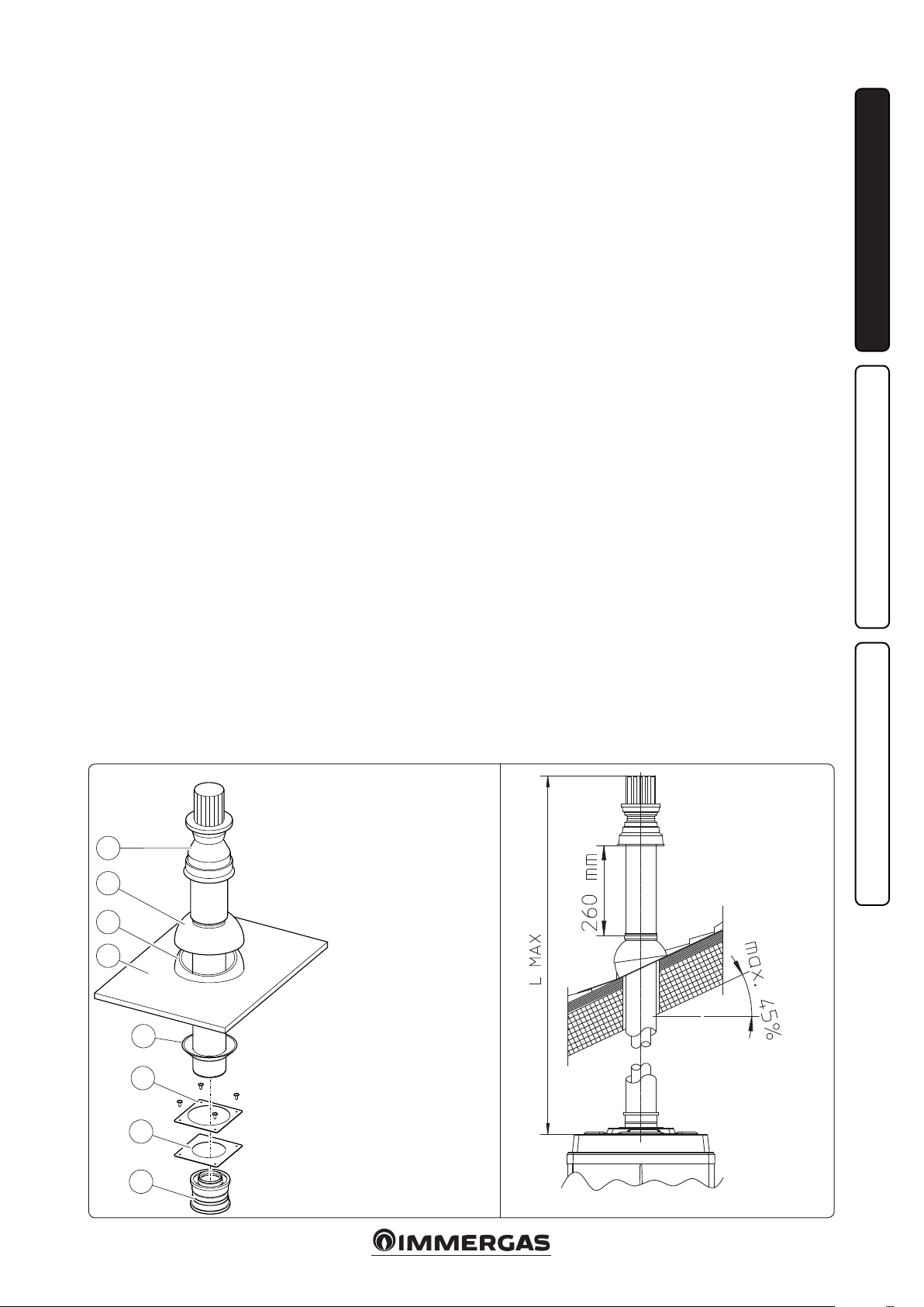
1.15 CONCENTRIC VERTICAL KIT
INSTALLATION.
Type C configuration, sealed chamber and
fan assisted.
Concentric vertical intake and exhaust kit. is
vertical terminal is connected directly to the outside of the building for air intake and ue exhaust.
N.B.: the vertical kit with aluminium tile enables installation on terraces and roofs with a
maximum slope of 45% (approx. 25°) and the
height between the terminal cap and half-shell
(260 mm) must always be observed.
Vertical kit with aluminium tile 80/125 Ø.
Kit assembly (Fig. 1-13): Install the 80/125 Ø
adapter (1) on the central hole of the boiler fully
home. Slide the gasket (2) along the adapter (1)
up to the relevant groove, Fix it to the lid using
the previously disassembled sheet steel plate (3)
Installation of the fake aluminium tile: replace
the tiles with the aluminium sheet (5), shaping
it to ensure that rainwater runs o. Position the
xed half-shell (6) on the aluminium tile and
insert the intake-exhaust pipe (7). Fit the 80/125
Ø concentric terminal pipe with the male end
(6) (smooth) to the female end of the adapter
(1) (with lip gasket) up to the stop; making sure
that the wall sealing plate (4) has been tted, this
will ensure sealing and joining of the elements
making up the kit.
• Maximum length (MAX L) (Fig. 1-13). e kit
with this conguration can be extended up to
a max. measurement of 15.0 m with Victrix Pro
80 2ErP, 11.0 m with Victrix Pro 100 2ErP and
6.0 m with Victrix Pro 120 2ErP, including the
terminal.
INSTALLERUSER
C33C33
8
7
6
5
e kit includes:
1 - Adaptor 80/125 Ø (1)
4
3
1 - Gasket (2)
1 - Ring (4)
1 - Aluminium tile (5)
1 - Fixed half-shell (6)
1 - Int./exhaust concentric terminal
80/125 Ø (7)
1 - Mobile half-shell (8)
2
1
1-12 1-13
MAINTENANCE TECHNICIAN
13
Page 14
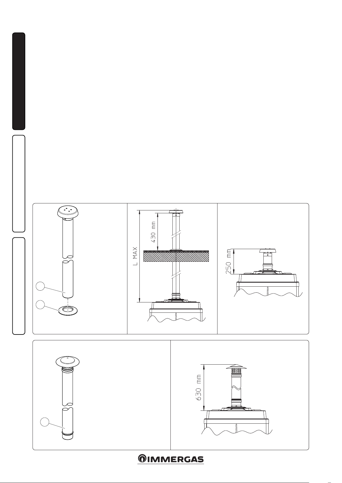
1.16 INSTALLATION OF VERTICAL
TERMINALS 80 Ø.
Configuration type B, open chamber and
forced draught.
80 Ø Vertical kit (plastic for indoor applications).
Kit assembly (Fig. 1-14): install the 80 Ø terminal
(2) on the central hole on the boiler up to stop,
making sure that the wall sealing plates (1) have
been tted. is will ensure the sealing eciency
of the kit components.
INSTALLERUSER
• Maximum length (MAX L) (Fig. 1-15). e kit
with this conguration can be extended up to
a max. measurement of 28.0 m with Victrix Pro
80 2ErP, 14.0 m with Victrix Pro 100 2ErP and
8.5 m with Victrix Pro 120 2ErP, including the
terminal.
Using the 80 Ø vertical terminal for direct discharge of the combustion products, the terminal
must be shortened (see quotas g. 1-16). e wall
sealing plate (1) must also be inserted in this case,
going up to stop on the boiler cover.
80 Ø Vertical kit (steel for outdoor applications).
Kit assembly (Fig. 1-17): install the 80 Ø terminal
(1) on the central hole on the boiler up to the
stop, ensuring the sealing eciency of the kit
components.
e 80 Ø steel terminal is used to install the boiler
outdoors with a direct exhaust. e terminal
cannot be shortened and once it is installed it
will extend out by 630 mm (Fig. 1-18).
MAINTENANCE TECHNICIAN
B23
e kit includes:
1 - Ring (1)
1 - 80 Ø exhaust
terminal (2)
B23
B23
2
1
1-14
B23
1-15
1-16
B23
e kit includes:
1 - Steel 80 Ø exhaust terminal (1)
1
1-17
1-18
14
Page 15
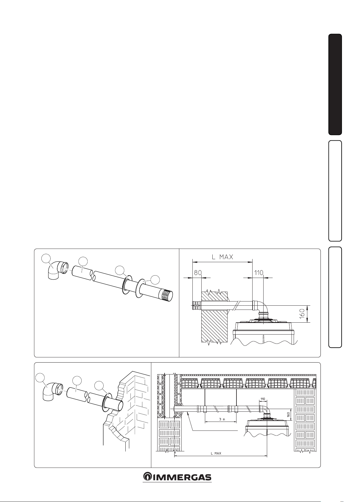
1.17 INSTALLATION OF 80 Ø
HORIZONTAL TERMINALS.
Configuration type B, open chamber and
forced draught.
80 Ø horizontal kit with wall ue exhaust.
Kit assembly (Fig. 1-19): install the 80 Ø bend (1)
with the male side (smooth) fully home on the
central hole of the boiler. Fit the exhaust terminal
(2) with the male end (smooth) to the female
end of the bend (1) up to the stop; making sure
that the internal (3) and external (4) wall sealing
plate has been tted. is will ensure sealing and
joining of the elements making up the kit.
Horizontal kit 80 Ø with exhaust in ue. Kit
assembly (Fig. 1-21): install the 80 Ø bend (1)
with the male side (smooth) fully home on the
central hole of the boiler. Fit the exhaust pipe (2)
with the male end (smooth) to the female end of
the bend (1) up to the stop; making sure that the
internal wall sealing plate (3) has been tted. is
will ensure sealing and joining of the elements
making up the kit.
• Maximum length (MAX L) (Fig. 1-20 and 22).
e kit with this conguration can be extended
up to a max. measurement of 28.0 m with Victrix
Pro 80 2ErP, 14.0 m with Victrix Pro 100 2ErP
and 8.5 m with Victrix Pro 120 2ErP, including
the terminal.
INSTALLERUSER
1
e kit includes:
1 - 90° 80 Ø bend (1)
1 - 80 Ø exhaust terminal (2)
1 - Internal ring (3)
1 - External ring (4)
1
e kit includes:
1 - 90° 80 Ø bend (1)
1 - 80 Ø drain pipe (2)
1 - Internal ring (3)
2
2
B23
B23
3
4
MAINTENANCE TECHNICIAN
1-19 1-20
B23 B23
3
Minimum slope 1.5 %
1-21
1-22
15
Page 16

1.18 FLUE DUCT SYSTEMS FOR VOIDS
AND CHIMNEYS.
Flue ducts may be installed in suitable voids or
chimneys provided that the relevant building
regulations permit this. Flue ducting systems
must be installed in strict accordance with the
manufacturers instructions.
Immergas ducting system 80 Ø. e "Green
Series" 80 Ø exible ducting system must only be
used with Immergas condensing boilers.
In any case, ducting operations must respect
the provisions contained in the standard and in
INSTALLERUSER
current technical regulations; in particular, the
declaration of conformity must be compiled at
the end of work and on commissioning of the
ducted system. e instructions in the project
or technical report must likewise be followed, in
cases provided for by the standard and current
technical regulations. e system or components
of the system have a technical life complying with
current standards, provided that:
- it is used in average atmospheric and envi-
ronmental conditions, according to current
regulations (in particular, by the standards
regarding: absence of combustion products,
dusts or gases that can alter the normal thermophysical or chemical conditions; existence
of temperatures coming within the standard
range of daily variation, etc.).
MAINTENANCE TECHNICIAN
Exhaust
Exhaust
B23
- Installation and maintenance must be performed according to the indications supplied
by the manufacturer and in compliance with
the provisions in force.
- e max. possible length of the 80 Ø exible
ducting vertical section is equal to 28.0 m for
Victrix Pro 80 2ErP, 14.0 m for Victrix Pro 100
2ErP and 8.5 m for Victrix Pro 120 2ErP. is
length is obtained considering the complete exhaust terminal, 1m of 80 Ø pipe in exhaust, two
90° 80 Ø bends at the boiler outlet to connect to
the ducting system and two direction changes
of the exible tube inside the ue/technical slot.
1.19 FLUE EXHAUST WITH BOILERS IN
CASCADE.
e boilers installed in cascade composed of
any number between 2 and 5 boilers, can be
manifolded to a unique ue exhaust pipe, which
ows into a ue.
Immergas supplied an appropriate and original
ue exhaust system separately to the boilers.
1.20 SYSTEM FILLING.
When the boiler has been connected, ll the system. Filling is performed at low speed to ensure
release of air bubbles in the water via the boiler
and heating system vents.
The boiler incorporates two automatic vent
valves tted on the circulator pump and on the
condensing module. Check if the cap is loose.
Open the radiator vent valves. Close radiator
vent valves when only water escapes from them.
N.B.: during these operations start up the circulation pump at intervals, acting on the main
switch positioned on the control panel. Vent the
circulation pump by loosening the front cap and
keeping the motor running. Tighten the cap aer
the operation.
Attention: this boiler is not equipped with an
expansion vessel on the system. It is mandatory
to install a closed expansion vessel to guarantee
correct boiler operation. e expansion vessel
must comply with the European Standards in
force. e dimensions of the expansion vessel
depend on the data relative to the central heating
system. Install a vessel whose capacity responds
to the requisites of the Standards in force (''R''
collection).
1.21 CONDENSATE TRAP FILLING.
On rst lighting of the boiler combustion products may come out the condensate drain; aer a
few minutes’ operation check that this no longer
occurs. is means that the trap is lled with
condensate to the correct level preventing the
passage of combustion products.
1.22 GAS SYSTEM STARTUP.
To start up the system, refer to the technical
standard in force: is divides the systems and
therefore the start-up operations into three
categories: new systems, modified systems,
re-activated systems.
In particular, for new gas systems:
- open windows and doors;
- avoid presence of sparks or open ames;
- bleed all air from the pipelines;
- check the seal of the internal system by following the instructions provided by the technical
regulations in force (refer to the pertaining local regulations for the "sealing test" on systems
served by single or cascade generators with a
nominal thermal capacity greater than 35 kW.
1.23 BOILER START UP IGNITION.
In order to issue the Declaration of Conformity
required by the regulations in force, one must
full the following requirements to commission
the boiler (the operations listed below must only
be performed by qualied personnel and in the
presence of sta only):
- check that the internal system is properly sealed
according to the specications set forth by
regulations in force; Up to operating pressures
of 40 mbar it is also possible to use the testing
method adopted by the technical regulations
in force for systems served by single appliances
(or in cascade set-up), with nominal thermal
capacities greater than 35 kW. For greater pressure levels you will need to refer to legislation
in force and/or other eectively tried and tested
methods;
- make sure that the type of gas used corresponds
to boiler settings;
- check that there are external factors that may
cause the formation of fuel pockets;
- switch the boiler on and check correct ignition;
- make sure the fan rpm matches the value provided in the book (Par. 3.18);
- ensure that the safety device intervenes in the
event of gas supply failure and check the relative
intervention time;
- check activation of the main switch located
upstream from the boiler and in the boiler;
- check that the intake/exhaust concentric terminal (if tted) is not blocked.
e boiler must not be started up even if only
one of the checks should be negative.
N.B.: the Immergas Authorised Aer-sales Centre
can carry out the initial boiler check (point 2.1)
required to activate the warranty of Immergas
solely upon completion of commissioning by an
installer. e test certicate and warranty is issued
to the user.
1-23
16
Page 17

1.24 CIRCULATION PUMP.
e boilers are supplied with a variable speed
circulator pump.
When the boiler is in the heating phase, pump
speed is dened by the setting of the parameters
“P27” and “P28” and varies so as not to exceed
the ∆T of 18 °C.
In domestic hot water mode the circulator pump
always runs at maximum speed.
Pump release. If, aer a prolonged period of
inactivity, the circulation pump is blocked,
unscrew the front cap and turn the motor sha
using a screwdriver. Take great care during this
operation to avoid damage to the motor.
1.25 KITS AVAILABLE ON REQUEST.
• Cascade and zones heat adjuster kit.
• Support kit for xing the heat adjuster to the
wall.
• Zone manager kit.
• Modulating room thermostat kit.
• External probe kit.
• System ow probe kit.
• DHW probe kit for external storage tank.
• Anti-freeze with -15 °C resistance kit.
• Individual boiler safety devices stub pipes kit.
• Boilers in cascade safety devices stub pipes kit.
• ree-way valve kit for coupling external storage tank unit.
• Individual boiler hydraulic manifold kit.
• Hydraulic connection manifolds kit with two
boilers in cascade.
• Additional boiler in cascade hydraulic manifold
kit.
• Flue exhaust manifold kit with ue adjusting
devices with two boilers in cascade.
• Flue exhaust manifold kit with ue adjusting
device with additional boiler in cascade.
• 80/125 Ø horizontal concentric kit.
• 80/125 Ø vertical concentric kit.
• 80 Ø horizontal kit with ue exhaust.
• 80 Ø horizontal terminal kit with wall ue
exhaust.
• 80 Ø vertical terminal kit.
e above-mentioned kits are supplied complete
with instructions for assembly and use.
INSTALLERUSER
Head available to the system.
Victrix PRO 80 2 ErP
Head (kPa)
B
A
Flow rate (l/h)
Key:
A = Available head
B = Power absorbed by the circulator
pump (dotted area)
Circulator pump absorbed power (W)
MAINTENANCE TECHNICIAN
1-24-A
17
Page 18
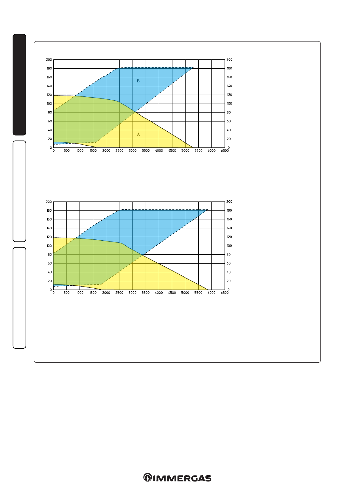
Head available to the system.
Victrix PRO 100 2 ErP
INSTALLERUSER
Head (kPa)
B
Victrix PRO 120 2 ErP
Head (kPa)
A
Flow rate (l/h)
A
Flow rate (l/h)
Circulator pump absorbed power (W)
B
Circulator pump absorbed power (W)
MAINTENANCE TECHNICIAN
Key:
A = Available head
B = Power absorbed by the circulator pump (dotted area)
1-24-B
18
Page 19

1.26 BOILER COMPONENTS.
INSTALLERUSER
Key:
1 - Draining funnel.
2 - Gas cock
3 - Pump
4 - Gas nozzle
5 - Overheating safety thermostat
6 - Burner
7 - System return regulation NTC probe
8 - System ow regulation NTC probe
9 - Condensing module air vent valve
10 - Flue probe
11 - Condensation module
12 - Air pressure switch
13 - Fumes hood
14 - Air intake pipe
15 - Igniter
19
16 - Heat-exchanger safety thermostat (manual reset)
17 - Heat exchanger safety thermal fuse
18 - Ignition electrode
19 - Detection electrode
20 - Condensation module cover
21 - Manifold cover
22 - Sleeve with seats for Venturi
23 - Condensate trap
24 - Air fan
25 - Gas valve
26 - System pressure switch
27 - Flow manifold
28 - 4 bar safety valve
29 - P.C.B.
30 - Sample points (air A) - (ue gas F)
MAINTENANCE TECHNICIAN
1-25
Page 20

1.27 HYDRAULIC DIAGRAM WITH OPTIONAL.
INSTALLERUSER
Key:
1 - Generator
2 - Manometer pocket
3 - Minimum pressure switch
4 - Probe for fuel shut-o valve bulb
5 - Manometer
6 - Damper coil
7 - Manometer-holder cock
8 - ermometer
MAINTENANCE TECHNICIAN
9 - Manual rearm thermostat
10 - Attachment for expansion vessel
11 - Manual rearm pressure switch
12 - Fuel shut-o valve
13 - Expansion vessel
14 - Boiler connection 3-way valve
15 - Hydraulic manifold/mixer
16 - Slurry collection brass lter
Attention: the sensitive elements of the automatic regulation and block circuit breaker switches
and of the thermometer (not supplied as standard
with the boiler) must be set-up as described in
the installation instructions in compliance with
the provisions of the "R" collection. Whenever the
generators are not installed in cascade according
to the instructions and the Immergas original
kits, the sensitive elements must be installed on
the ow piping to the central heating system,
immersed in the current of water at not more
than 0.5 metres from the boiler outlet.
the boilers must be installed in the congurations
and with their own original Immergas cascade
and safety kits.
liability whenever the installer does not use the
devices and Immergas original kits or uses them
improperly.
Immergas S.p.a. declines all
1-26
20
Page 21

1.28 INSTALLATION EXAMPLES OF INDIVIDUAL BOILER.
15 - Storage tank unit feeding pump
16 - Zone 1 safety thermostat (CMI-1)
17 - Zone 2 safety thermostat (CMI-2)
19 - Fuel shut-o valve bulb
20 - Manometer-holder cock
21 - ermometer
22 - Manual rearm thermostat
23 - Manual rearm pressure switch
24 - Attachment for expansion vessel
25 - Expansion vessel
26 - Manifold/mixer
27 - External storage tank unit
28 - Fuel shut-o valve
29 - Non return valve
30 - Slurry collection system lter
31 - Manometer pocket
32 - Damper coil
33 - Manometer
34 - Minimum pressure switch
INSTALLERUSER
Key:
1 - Generator
2 - Cascade and zone regulator
3 - Zone manager
4 - Modulating room thermostat
5 - External probe
6 - Zone 1 temperature probe (CMI-1)
7 - Zone 2 temperature probe (CMI-2)
8 - Common ow probe
9 - Storage tank unit temperature probe
10 - Zone 1 mixing valve (CMI-1)
11 - Zone 2 mixing valve (CMI-2)
12 - Zone 1 central heating circuit pump (CMI-1)
13 - Zone 2 central heating circuit pump (CMI-2)
14 - Zone 3 direct circuit pump (CD)
MAINTENANCE TECHNICIAN
1-27
21
Page 22

USE AND MAINTENANCE
2
INSTRUCTIONS
2.1 CLEANING AND MAINTENANCE.
Warning: to preserve the boiler’s integrity and
keep the safety features, performance and reliability, which distinguish it, unchanged over time,
you must at least execute maintenance operations
on a yearly basis in compliance with what is stated
in the relative point at “annual check and maintenance of the appliance”. Annual maintenance
is essential to validate the conventional warranty
INSTALLERUSER
of Immergas. We recommend stipulating a yearly
cleaning and maintenance contract with your
zone Immergas Authorised Aer-sales Service.
2.2 AERATION AND VENTILATION OF
THE INSTALLATION ROOMS.
Consult the "Aeration and ventilation of installation rooms" chapter contained herein and, in
any case, always refer to the provisions set forth
by standards and all legislation in force.
2.3 GENERAL WARNINGS.
Use of the boiler by unskilled persons or children
is strictly prohibited.
For safety purposes, check that the concentric
air intake/flue exhaust terminal (if fitted), is
not blocked.
If temporary shutdown of the boiler is required,
proceed as follows:
a) drain the heating system if anti-freeze is not
used;
b) shut-o all electrical, water and gas supplies.
N.B.: in the case of maintenance interventions
on the boiler that lead to the closure of one or
both system cut-o cocks, the boiler must be o.
In the case of work or maintenance to structures
located in the vicinity of ducting or devices for
ue extraction and relative accessories, switch o
the appliance and on completion of operations
ensure that a qualied technician checks eciency of the ducting or other devices.
Never clean the appliance or connected parts
with easily ammable substances.
Never leave containers or ammable substances
in the same environment as the appliance.
• Attenzione: the use of components involving
use of electrical power requires some fundamental rules to be observed:
- do not touch the appliance with wet or moist
parts of the body; do not touch when bare-
MAINTENANCE TECHNICIAN
foot;
- do not pull electric cables;
- the appliance power cable must not be re-
placed by the user;
- in the event of damage to the cable, switch
off the appliance and contact exclusively
qualied sta for replacement;
- if the appliance is not to be used for a certain
period, disconnect the main power switch.
22
Page 23

2.4 CONTROL PANEL.
INSTALLERUSER
Key:
1 - Main switch
2 - CH temperature adjustment buttons
3 - Sliding door
4 - DHW temperature adjustment buttons (optional)
5 - Boiler manometer
6 - Summer / winter mode button (A)
7 - Reset, info, conrm parameters button (B)
8 - Multifunction button: anomalies records, DHW exclusion (C)
9 - Multi-function display
10 - CH function enabled
11 - Temperature indicator, boiler info and error codes
12 - Not used
13 - Boiler parameter and info display
14 - Not used
15 - Not used
16 - Parameter adjustment in progress
17 - Boiler in stand-by
18 - External probe connected (optional)
19 - unit of measurement
20 - DHW production phase operation enabled (optional)
21 - Domestic hot water exclusion
22 - Flame detection symbol
23 - Resettable presence of anomalies
24 - Pump running
25 - Summer mode
2.5 USING THE BOILER.
Before ignition, make sure that the system is
full of water, checking that the manometer (5)
indicates a base value at which the system has
been designed and calculated and however not
less than 0.5 bar.
- Open the gas cock upstream from the boiler.
- Turn the main switch, and the boiler runs a
self-diagnosis. It will then go back to the status
it was in prior to being switched o.
• “A” operating mode button( ): with
the boiler on, press the button (A) repeatedly
to change the operating mode. It will alternate
from summer mode (
only) to winter mode (room and DHW heating).
) ) (DHW heating
N.B.: the DHW heating function is only active
in presence of the specic optional kit (tank
probe automatic recognition).
With the boiler on but not running, the screen
will display the ow probe temperature reading.
2-2
2-1
If requested, the boiler switches on and the relative symbols will be displayed, indicating the
ow probe temperature reading.
2-3
Warning: anomalies with a code over “90” are
not saved in the anomaly records.
- Slave boiler anomalies (simple cascade
installation). Slave boiler anomalies are displayed on the Master boiler. Aer entering the
menu, press + and - (ref. 8 g. 2-1) to alternate
between Master “bu 0” and Slave “bu 1” boilers.
MAINTENANCE TECHNICIAN
23
Page 24

• Summer ( ): in this mode the boiler only
operates for domestic hot water heating.
By pressing the + or - buttons just once (4
g. 2-1) it is possible to read the temperature
setting. By pressing them again you can change
the settings as needed. Press “B” to save the
new value. e temperature reading will ash
during adjustment. If a certain amount of time
lapses without saving the value, the boiler will
exit setting mode and maintain the previous
setting.
INSTALLERUSER
• Winter: in this mode the boiler functions both
for heating domestic hot water and heating the
environment.
By pressing the + or - (2 g. 2-1) buttons once,
you can view the temperature setting. By pressing them again you can change the setting as
needed. You will need to press “B” to save the
new value. e temperature reading will ash
during adjustment. If a certain amount of time
lapses without saving the value, the boiler will
exit setting mode and maintain the previous
setting.
• DHW exclusion ( ): with the boiler set up
for DHW heating, press “C” momentarily to
exclude DHW heating mode operation. To
restore DHW heating, press "C" again.
• Anomaly records: press and hold “C” down to
access the records of the last 8 anomalies that
have aected the boiler (list from H i 0 to H i 7,
where H i 0 is the most recent anomaly). When
2-4
you are in the menu, the screen will display, in
order, number “bu 0”, the number and code for
the anomaly.
To scroll through the list, press buttons + and
- (ref. 2 g. 2-1).
To exit the menu, press and hold "C" down
again.
Attention: anomalies with the “FE” code are
not saved in the anomaly records.
Simple cascade: in case of simple cascade,
anomalies will be displayed on the master boiler
(without the “0” sux on the Slave boiler) and
slave boiler anomalies are displayed on the master boiler with sux “1”.
Example: “0A1” anomaly
Anomaly on Master boiler = 0A1
Anomaly on Slave boiler = A1
2-7
Slave boiler anomaly displayed on Master boiler
= 1A1
2-8
• Stand-by mode ( ): by pressing buttons “A”
and “C” at the same time it is possible to place
the boiler in stand-by.
MAINTENANCE TECHNICIAN
In this mode the boiler is considered powered
on but not active. Accordingly, the appliance's
anti-freeze function is guaranteed. To turn it
back on simply press "B".
2.6 TROUBLESHOOTING.
e boiler will let you know of any anomalies by
2-5
the ashing screen and code. ere are dierent
types of codes that can be divided up as follows:
- “0Axx” for resettable anomalies (fig. 2-9).
(Before resetting the anomaly you will need to
wait for the boiler to nish its post-ventilation
function, which lasts approximately 60 seconds).
- “0Exx” and “FExx” for non-resettable anomalies.
e “xx” sux stands for the error code described in the following tables.
2-6
24
Page 25

Error
Code
0A1 No ignition block
0A2 Parasite ame block
0A3 Overheating block
0A4 Air pressure switch
0A5 Fan signal anomaly is occurs if the fan speed is incorrect. Press the Reset button (1)
0A7
0A8 Flame circuit anomaly
0A9
0A15
0A16
0A17
0A18
0A21 P.C.B. error An error is detected on the P.C.B. and the boiler does not start up Press the Reset button (1)
0A30
0A31
0A37
0A43
0A44
0A80
(1) If the block or anomaly persists, contact an authorised company (e.g. Immergas Technical Aer-Sales Service).
(2) If normal operating conditions are restored, the boiler re-starts without having to be reset.
Anomaly signalled Cause Boiler status / Solution
In the event of request of room central heating or domestic hot water
Flue temperature
anomaly
Gas valve electric
circuit anomaly
Flow and return NTC
probe temperature
detection incorrect (in
stand-by)
Poor thermal ow
NTC probe contact
Poor thermal return
NTC probe contact
Flow and return NTC
probe temperature
detection incorrect
Flow NTC probe in
short circuit
Flow NTC probe
outside the operating
range
Insucient system
pressure
Return NTC probe in
short circuit
Return NTC probe
outside the operating
range
Flow and return NTC
probe connection error
production, the boiler does not switch on within the preset time.
Upon appliance commissioning or aer extended downtime, it may
be necessary to eliminate the block.
is occurs during the power-on phase in the event of a leak on the
detection circuit or anomaly in the ame control unit.
During normal operation, if a fault causes excessive overheating internally, the boiler goes into overheating block.
During the heat request phase, the board detects the stuck/open
contacts of the air pressure switch.
If the boiler fails, the ue circuit will provide an excessively high
temperature reading and the boiler will switch o.
During the ignition phase an anomaly was detected on the electronic
ame control circuit and the boiler switches o.
e board detects an anomaly in the gas valve circuit. Before replacing
the board, verify the absence of short circuits on gas valve and related
connector.
With the boiler in stand-by, the board detects an anomalous dierence
between the NTC probe ow and return temperatures. e error may
be caused by a failure in one of the two probes
During boiler operation the board does not detect a change in the ow
NTC probe temperature. e error may be caused by a poor thermal
probe contact or a system with excessive thermal inertia.
During boiler operation the board does not detect a change in the return
NTC probe temperature. e error may be caused by a poor thermal
probe contact or a system with excessive thermal inertia.
If the board detects a sudden drop in temperature on one of the two
NTC probes (ow and return), it will report an anomaly. is may be
caused by the failure of one of the two probes
e board detects a short circuit on the ow NTC probe. Press the Reset button (1)
e board detects an open contact on the ow NTC probe. Press the Reset button (1)
If the system pressure is too low the boiler switches o.
e board detects a short circuit on the return NTC probe Press the Reset button (1)
e board detects an open contact on the return NTC probe. Press the Reset button (1)
If the electrical connection between the two NTC probes is switched
around, the board will detect the anomaly (it may be necessary to wait
3 minutes for the error to be detected).
Press the Reset button (1)
Press the Reset button (1)
Press the Reset button (1)
Press the Reset button (1)
Press the Reset button (1)
Press the Reset button (1)
Press the Reset button (1)
Press the Reset button (1)
Press the Reset button (1)
Press the Reset button (1)
Press the Reset button (1)
Check on the boiler pressure gauge (1)
that the system pressure is between 1÷1.2
bar and restore the correct pressure if
necessary.
(2) (1)
Press the Reset button (1)
INSTALLERUSER
MAINTENANCE TECHNICIAN
25
Page 26

Error
Code
0E2 Parasite ame block
0A13 Maximum N° of reset Number of allowed resets that have already performed.
0E25 P.C.B. error An error is detected on the P.C.B. and the boiler does not start up (2) (1)
0E32
INSTALLERUSER
0E33
0E34
0E37
0E45
0E46
0E81
0E98
0E99
(1) If the block or anomaly persists, contact an authorised company (e.g. Immergas Technical Aer-Sales Service).
(2) If normal operating conditions are restored, the boiler re-starts without having to be reset.
Anomaly signalled Cause Boiler status / Solution
is occurs during the power-on phase in the event of a leak on the
detection circuit or anomaly in the ame control unit.
DHW NTC probe in
short circuit
DHW NTC probe
outside the operating
range
Low power supply
voltage
Pressure or ow rate
insucient system
Flue NTC probe in
short circuit
Flue NTC probe
outside the operating
range
Flow and return NTC
probe temperature
detection incorrect (in
stand-by)
Simple cascade communication anomaly
Internal communication anomaly
e board detects a short circuit on the DHW NTC probe (2) (1)
e board detects an open contact on the DHW NTC probe. (2) (1)
is occurs when the power supply voltage is lower than the allowed
limits for the correct boiler operation.
If the system pressure is too low the boiler switches o.
e board detects a short circuit on the ue NTC probe. (2) (1)
e board detects an open contact on the ue NTC probe. (2) (1)
With the boiler in stand-by, the board detects an anomalous dierence
between the NTC probe ow and return temperatures. e error may
be caused by a failure in one of the two probes
Occurs if the communication between the display boards breaks down
A communication error has been detected between the display board
and the boiler's P.C.B.. In the event of simple cascade, even in the case
of a communication error between the display boards.
(2) (1)
Attention: it is possible to reset the anomaly up to 5 consecutive times within 15
minutes. (1) By switching the appliance
on and o the 5 attempts are re-acquired.
(2) (1)
Check on the boiler pressure gauge (1)
that the system pressure is between 1÷1.2
bar and restore the correct pressure if
necessary.
(2) (1)
(2) (1)
Check the bus’ electric connection.
Perform the Auto detection.
Check whether the soware versions
match.
(2) (1)
Check the boiler’s wiring.
Check the bus’ electric connection.
Perform the Auto detection in the event
of simple cascade installation.
(2) (1)
MAINTENANCE TECHNICIAN
Error
Code
FE94 Display board anomaly An error is detected on the display's P.C.B.. (2) (1)
FE95
FE96
FE97 Conguration error
(1) If the block or anomaly persists, contact an authorised company (e.g. Immergas Technical Aer-Sales Service).
(2) If normal operating conditions are restored, the boiler re-starts without having to be reset.
Anomaly signalled Cause Boiler status / Solution
Shared common ow
probe short-circuited
or out of range
External probe
anomaly
e board detects an incorrect value on the ow NTC probe or “P38”
parameter not set correctly..
An anomaly is detected on the external probe.
P.C.B. conguration error.
is may happen when the P.C.B. is changed It may occur also in the
event of replacement of the electronic boards with an incorrect model..
26
(2) (1)
Check the boiler conguration, check
the external probe (2) (1)
Check the conguration parameters.
Perform the Auto detection.
(2) (1)
Page 27

2.7 INFO MENU.
Press and hold down "B" to access the info menu
containing all of the various information relative
to boiler operation.
Once you are inside the menu, you will momentarily see the parameter number followed
by the value.
2-10
To scroll through the various parameters, press
buttons + and - (ref. 2 g. 2-1).
To exit the menu, press and hold "B" down again.
While the parameter value is being displayed it
is possible to momentarily see the relative code
again by pressing button "A". e viewable parameters are listed in the following tables.
2.8 BOILER SHUTDOWN.
Disconnect the main switch (1) taking it to the
“0” position and close the gas cock upstream
from the appliance.
Never leave the boiler switched on if le unused
for prolonged periods.
2.9 RESTORING CENTRAL HEATING
SYSTEM PRESSURE.
Periodically check the system water pressure.
e boiler manometer should indicate a value
not below 0.5 bar.
If the pressure is below 0.5 bar (with cold system)
the water inside the system must be restored.
N.B.: close the valve aer the operation.
If pressure values reach around 4 bar the safety
valve may be activated.
In this case contact a professional technician
for assistance.
In the event of frequent pressure drops, contact
qualied sta for assistance to eliminate possible
system leakage.
In this case, remove water from an air vent valve
of a radiator until reaching pressure of 1 bar, or
ask for assistance from professionally qualied
personnel.
In the event of frequent pressure drops, contact
qualified staff for assistance to eliminate the
possible system leakage.
2.10 SYSTEM DRAINAGE.
To drain the boiler, use the appropriate system
drain tting.
Before draining, ensure that the system lling
valve is closed.
2.11 ANTIFREEZE PROTECTION.
e boiler is supplied with an antifreeze function
as standard that activates the function of the
pump and the burner when the system water
temperature in the boiler falls below 5°C. e
antifreeze function is guaranteed if the boiler is
fully operative, if it is not in "block" status and
is electrically powered with the main switch on
"ON". To avoid keeping the system switched on
in case of a prolonged absence, the system must
be drained completely or antifreeze substances
must be added to the heating system water. In
systems that are drained frequently, lling must
be carried out with suitably treated water to
eliminate hardness that can cause lime-scale.
2.12 CASE CLEANING.
Use damp cloths and neutral detergent to clean
the boiler casing. Never use abrasive or powder
detergents.
2.13 DECOMMISSIONING.
In the event of permanent shutdown of the boiler,
contact professional sta for the procedures and
ensure that the electrical, water and gas supply
lines are shut o and disconnected.
INSTALLERUSER
Info menu
Menu item Description Unit of measurement
P01 Flame current μA
P02 Flow NTC probe temperature reading °C / °F
P03 Return NTC probe temperature reading °C / °F
P04 DHW NTC probe temperature reading (if installed) °C / °F
P05 Not used P06 Operating power %
P07 Fan speed requested by the system RPM / 50
P08 Current fan speed RPM / 50
P09 Flue NTC probe temperature reading °C / °F
P10
P11 External probe temperature reading (if installed) °C / °F
P12 Not used P13 Flow temperature requested by the system in heating °C / °F
P14 Flow temperature requested by the system in DHW °C / °F
P15 Not used P16 Number of burners on in simple cascade mode no.
P17 P17 Number of displays on no
Common ow probe temperature reading (if installed)
or boiler ow probe (based on the system’s conguration)
°C / °F
27
MAINTENANCE TECHNICIAN
Page 28

BOILER COMMISSIONING
3
INITIAL CHECK
To commission the boiler:
- make sure that the declaration of conformity
for installation is supplied with the appliance;
- make sure that the type of gas used corresponds
to boiler settings;
- check connection to a 230V-50Hz power
mains, correct L-N polarity and the earthing
connection;
INSTALLERUSER
- switch the boiler on and check correct ignition;
- check the CO2 in the fumes at maximum and
minimum ow rate;
- make sure the fan rpm matches the value provided in the book (Par. 3.18);
3.1 HYDRAULIC DIAGRAM.
MAINTENANCE TECHNICIAN
- check activation of the safety device in the event
of no gas, as well as the relative activation time;
- check the intervention of the main switch
located upstream of the boiler and in the boiler;
- check the existing draught during normal
functioning of the appliance, e.g. a draught
gauge positioned at the exit of the appliance
combustion products;
- check that there is no backow of combustion
products into the room, even during functioning of fans;
- check that the intake and/or exhaust terminals
are not blocked;
- ensure activation of all adjustment devices;
- seal the gas ow rate regulation devices (if
settings are modied);
- check sealing eciency of water circuits;
- check ventilation and/or aeration of the installation room where provided.
If even only a single safety check oers a negative
result, do not commission the system.
Key:
1 - Draining funnel on view
2 - 4 bar safety valve
3 - Boiler draining valve
4 - System pressure switch
5 - Flow manifold
6 - Gas valve
7 - Air fan
8 - Gas nozzle
9 - Air intake pipe
10 - Detection electrode
11 - Condensation module cover
12 - Condensation module
13 - Fumes hood
14 - Air sample point
15 - Flue sample point
16 - Condensing module air vent valve
17 - System ow regulation probe
18 - Air pressure switch
19 - System return regulation probe
20 - Over temperature safety thermostat
21 - Heat-exchanger safety thermostat
(manual reset)
22 - Flue probe
23 - Burner
24 - ermofuse
25 - Ignition electrode
26 - Manifold cover
27 - Sleeve with seats for Venturi
28 - Boiler circulator pump
29 - Condensate trap siphon
28
M - System ow
SC - Condensate drain
G - Gas supply
R - System return
3-1
Page 29

3.2 230 V CIRCUIT WIRING DIAGRAM.
INSTALLERUSER
Colour key:
BK - Black
BL - Blue
BR - Brown
G - Green
GY - Grey
OR - Orange
P - Purple
PK - Pink
R - Red
Y - Yellow
Y/G - Yellow / Green
W - White
W/BK - White / Black
4
5
7
Free contact Max. 230 Vac - 0,8 A Max. cosφ ≥ 0,6
Free contact Max. 230 Vac - 0,8 A Max. cosφ ≥ 0,6
1 - External reset (optional)
2 - Alarm.
3 - System side pump Potential.
4 - External relay (optional)
5 - Coil 230 Vac - Max. 0.1 A
6 - External pump (Driven by M1 pump)
6
5
4
3
2
1
7 - D.H.W. pump
MAINTENANCE TECHNICIAN
For safety reasons the P.C.B. envisions a fuse
that cannot be restored in series with the electric
power supply of the gas valve.
Congure the corresponding parameters when
connecting in “simple cascade”, or when connecting in “system side ow probe”, or “D.H.W.
p um p”.
29
Key:
A2 - P.C.B.
A4 - Display board
E1 - Ignition electrode
E2 - Detection electrode
G2 - Igniter
M1 - Boiler circulator pump
M20 - Fan
M30 - ree-way valve (optional)
S1 - Main switch
X90 - Boiler conguration jumper
Y1 - Gas valve
3-2
Page 30

3.3 VERY LOW VOLTAGE WIRING DIAGRAM.
INSTALLERUSER
Colour key:
BK - Black
BL - Blue
BR - Brown
G - Green
GY - Grey
OR - Orange
P - Purple
PK - Pink
R - Red
Y - Yellow
Y/G - Yellow / Green
W - White
W/BK - White / Black
1 - Testing
2 - “Simple cascade” communication bus
3 - 0 - 10 V analogue input
1
3
1
MAINTENANCE TECHNICIAN
For "WE-BUS", "0-10", "Simple BUS cascade"
connection, remove the X40 bridge.
A thermostat can be used instead of B2 (set the
P29 = 17 parameter).
2
e "Remote control for single high power boiler"
must be connected to the "M" and "O" terminals
(set the address to zero).
(manual reset)
E4 - Safety thermostat
E5 - -Heat-exchanger safety thermostat
E13 - Flue safety thermofuse
M1 - Boiler circulator pump
M20 - Fan
S5 - System pressure switch
S6 - Air pressure switch
S20 - ON/OFF room thermostat (optional)
X40 - Room thermostat jumper
Key:
A2 - Electronic board
A4 - Display board
B1 - Flow probe
B1-2 - System side ow probe (optional)
B2 - Domestic hot water probe (optional)
B4 - External temperature probe (optional)
B5 - Return probe
B10 - Flue probe
3-3
Congure the corresponding parameters when
connecting in “simple cascade”, or when connecting in “system side ow probe”, or “D.H.W.
p um p”.
30
Page 31

1
3.4 D.H.W. PUMP BOILER AND TANK PROBE WIRING DIAGRAM.
3 4
3.5 COMMON FLOW PROBE AND 3WAY BOILER WIRING DIAGRAM.
1
3 4
2
Key:
B1-2 -System ow probe (NTC)
B2 - Domestic hot water probe (NTC)
B4 - External probe
M2 - Plant CH pump
M3 - Domestic hot water pump
Note (probe B1-2, B2, B4):
- Connection cable diameter 3÷7 mm
- Cable section 0.5 ÷ 1.5 mm
2
INSTALLERUSER
1 - External relay (optional)
2 - 230 Vac 50 Hz
3 - “IT”-“IK” outlet =
230 Vac - 0,8 A Max. cosφ ≥ 0,6
4 - “C”-“D” inlet = Clean contact
Max. 230 Vac - 0,8 A Max. cosφ ≥ 0,6
3-4
2
Key:
B1-2 - System ow probe (NTC)
B2 - Domestic hot water probe (NTC)
B4 - External probe
M2 - Plant CH pump
M30 - 3-way valve
Note (probe B1-2, B2, B4):
- Connection cable diameter 3÷7 mm
- Cable section 0.5 ÷ 1.5 mm
2
1 - External relay (optional)
2 - 230 Vac 50 Hz
3 - “IT”-“IS"-"IK” outlet =
230 Vac - 0,8 A Max. cosφ ≥ 0,6
4 - “C”-“D” inlet = Clean contact
Max. 230 Vac - 0,8 A Max. cosφ ≥ 0,6
3.6 SIMPLE CASCADE BOILER WITH D.H.W. PUMP AND TANK PROBE WIRING DIAGRAM.
1 - External relay (optional)
2 - 230 Vac 50 Hz
3 - “IT”-“IK” outlet =
230 Vac - 0,8 A Max. cosφ ≥ 0,6
4 - “C”-“D” inlet = Clean contact
Max. 230 Vac - 0,8 A Max. cosφ ≥ 0,6
Note (probe B1-2, B2, B4):
- Connection cable diameter 3 ÷ 7 mm
- Cable section 0.5 ÷ 1.5 mm
1
3 4
2
2
3-5
Key:
B1-2 - System ow probe (NTC)
B2 - Domestic hot water probe (NTC)
B4 - External probe
M2 - Plant CH pump
M3 - Domestic hot water pump
Note (Connection bus):
- Connection cable diameter 3÷7 mm
- Cable section 0.5 ÷ 1.5 mm
2
- Maximum length 3 m
Note: Probes B1-2, B2, B4 must be connected
to the MASTER boiler.
3-6
MAINTENANCE TECHNICIAN
31
Page 32

3.7 TROUBLESHOOTING.
N.B.: maintenance interventions must be carried
out by an authorised company (e.g. Immergas
Aer-Sales Technical Assistance Service).
- Smell of gas. Caused by leakage from gas circuit
pipelines. Check sealing eciency of gas intake
circuit.
- Repeated ignition blocks. No gas, check the
presence of pressure in the network and that
the gas adduction valve is open. Incorrect
adjustment of the gas valve, check the correct
calibration of the gas valve.
INSTALLERUSER
- Irregular combustion or noisiness. It may be
caused by: a dirty burner, incorrect combustion
parameters, intake-exhaust terminal not correctly installed. Clean the above components
and ensure correct installation of the terminal,
check correct setting of the gas valve (O-Set
setting) and correct percentage of CO2 in ue
gases.
- e over temperature safety thermostat, the
ow probe or the return probe are triggered
frequently. It can depend on the lack of water in
the boiler, little water circulation in the system
or blocked pump. Check on the manometer
that the system pressure is within established
limits. Check that the radiator valves are not
closed and also the functionality of the pump.
In addition:
check that the exchanger safety thermostat has
not intervened. If it has, check the integrity of
the module and ceramic bre panel, replace
the cover gasket of the manifold and reset the
thermostat by pressing the specic button.
Also check the integrity of the thermofuse, and
if it has been triggered it will be necessary
to check the integrity of the module and the
ue circuit.
- Drain trap clogged. is may be caused by
dirt or combustion products deposited inside.
Check, by means of the condensate drain cap,
that there are no residues of material blocking
the ow of condensate.
- Heat exchanger clogged. is may be caused by
the trap being blocked. Check, by means of the
condensate drain cap, that there are no residues
of material blocking the ow of condensate.
- Noise due to air in the system. Check that system lling and air bleeding has been performed
according to the requirements.
- Noise due to air inside the condensation
MAINTENANCE TECHNICIAN
module. Use the manual air vent valve (Fig.
1-25 Ref. 9) to eliminate any air present in the
condensation module. When the operation has
been performed, close the manual vent valve.
- No DHW is produced. e boiler is equipped
with a function that automatically recognises
when there is an optional DHW probe, and an
anomaly is reported if there is a failure aecting
the DHW NTC probe. If there is a power outage, or if the boiler is switched o and back on
again during the failure, it will not be possible
to detect said failure, but it will, however, be
recorded in the errors anomaly records.
In case of ΔT > 35 °C, the boiler lowers the
power to avoid surpassing that value. When
this status is on, the ow temperature symbol
ashes.
3.8 CONTROL FUNCTION AIR FLOW
RATE.
With ignition request, before the start of the fan,
the condition of the pressure switch contact is veried. If this is detected closed, the continuation
of the cycle is prevented.
Aer a delay time of about 50 seconds, there is
a permanent block and fault “0A4” is signalled.
If the detected contact is open, the fan activates
at the “air pressure switch control” speed (3300
rpm). When the pressure switch is closed, the fan
switches to the ignition speed, and the ignition
cycle continues ignoring the pressure switch
condition.
If during operation at the “air pressure switch
control” speed (3300 rpm) the pressure switch
does not close, aer a time of about 50 seconds
there is a permanent block and the fault “0A4”
is signalled.
3.9 PROGRAMMING THE BOILER P.C.B.
e boiler is prepared for possible programming
of several operation parameters. By modifying
these parameters as described below, the boiler
can be adapted according to specic needs.
- Access programming by pressing and holding
down buttons “B” and “C”.
3-3
- Scroll through the parameters by pressing the
+ and - heating adjustment buttons,
3-4
- Change the parameter by pressing the + and -
DHW adjustment buttons.
3-5
- Save the parameters by switching from one
parameter to the next or by pressing “B”.
3-6
- Exit the programming mode by pressing and
holding down buttons “B” and “C” or wait
approximately 2 minutes without touching the
buttons.., the boiler will then run a self-diagnosis of the parameters by displaying “PARA”
followed by “Auto”.
- While the value of a parameter is being displayed, press “B” quickly to see the code again.
32
Page 33

Programming menu
Menu item Description Adjustment range Default value
P01 CH Set is denes the boiler's ow temperature during heating 20 ÷ P02 °C 85
P02 Max CH Set
P03 Heating Hysteresis is denes the power-o hysteresis during the heating phase 2 ÷ 10 °C 5
P04 Anti-cycle CH
P05 CH min time
P06 CH ramp
CH post-
P07
circulation
Available max
P08
heat out
Available max
P09
heat out
P10 - Not used 14 l / minutes
Electrodes anti-
P11
humidity
P12Boiler’s
P12
modulation ratio
P13 Boiler power
External probe
P14
curve
External probe
P15
oset
P16 DHW set is denes the DHW temperature 35 ÷ 65 °C 65 °C
External D.H.W /
P17
3-waypump
P18 DHW hysteresis
DHW post-
P19
circulation
Available max
P20
DHW pow
Available max
P21
DHW pow
DHW ow
P22
temperature with
thermostat
P23 DHW modulation
DHW o
P24
increment
P25 Max fan Speed
is denes the maximum settable ow temperature during
heating
is is used to set a waiting time to avoid the boiler from
switching on multiple times and frequently during CH mode
is is the amount of time that the boiler needs to stabilise,
when the burner runs at minimum power for the set amount
of time
e amount of time that the boiler takes to reach the required
temperature, number of degrees per minute (0 means no
ramp)
e amount of CH post circulation once the CH phase is
nished
is denes the maximum power percentage to be used
during the set CH phase
is denes the minimum power percentage to be used
during the set CH phase
is denes fan speed and operating mode, to avoid humidity
inside the condensing module, which could otherwise
cause the electrodes to malfunction (0 = disabled function,
recommended value = 40) (RPM speed is calculated by
multiplying the value displayed by 50)
It denes the boiler’s modulation ratio
(Do not modify)
Used to calculate the boiler power in the event of simple
cascade.
is is used to select the external probe operating curve
(optional) (0 = disabled probe)
is denes the CH oset in relation to the selected external
probe curve
- With a single boiler it controls an external 3-way.
- With single boiler and common ow probe, it lets you
choose between an external D.H.W pump and a 3-way one.
- With a simple cascade, it manages a D.H.W. pump
(downstream an hydraulic separator).
is denes the DHW power-on hysteresis during CH 2 ÷ 10 °C 5 °C
is is the post circulation time during DHW, once DHW
production is nished
is denes the maximum power percentage to be used
during the set DHW phase
is denes the minimum power percentage to be used
during the set DHW phase
In combination with a storage tank and a separate thermostat,
this denes the ow temperature during DHW operation
Summed with the “Set San” (P16) parameter, this denes
the ow temperature set that the boiler has to modulate the
power on during DHW
is denes the time that the boiler allows the burner to
switch o during DHW, by an increment of 5 °C on top of the
ow temperature
is denes the max fan speed and therefore the maximum
relative boiler operating power (RPM speed is calculated by
multiplying the value displayed by 50)
20 ÷ 95 °C 85
0 ÷ 15 minutes 3 minutes
3 ÷ 10 minutes 3 minutes
0 ÷ 60 °C/minute 4 °C/minute
1 ÷ 30 minutes 3 minutes
P09 ÷ 100% 100%
0 ÷ P08% 0%
P26 ÷120 0
0 ÷ 100% 10%
0 ÷ 255 kW
0 ÷ 10 0
20 ÷ 70 °C 30 °C
0 = 3 Ways
1 = D.H.W. pump
0 ÷ 180 seconds 60 seconds
P21 ÷ 100 % 50 %
0 ÷ P20 % 0 %
35 ÷ 90 °C 80 °C
5 ÷ 30 °C 15 °C
0 ÷ 255 seconds 60 seconds
P26 ÷ 255 RPM
x 50
80 kW = 75
100 kW = 90
120 kW = 115
80 kW Met. 132
80 kW LPG 131
100 kW Met. 134
100 kW LPG 127
120 kW Met. 140
120 kW LPG 140
Customised
Value
INSTALLERUSER
MAINTENANCE TECHNICIAN
33
Page 34

P26 Min fan Speed
P27 Min pump speed
INSTALLERUSER
P28
P29
P30
P31
P32 Set Resc Min
P33
P34
P35
P36
P37 0 ÷ 10 V inlet
P38
Programming menu
Menu item Description Adjustment range Default value
80 kW Met. 27
80 kW LPG 25
100 kW Met. 26
100 kW LPG 25
120 kW Met. 26
120 kW LPG 25
1
46
0
Pump speed
during burner
ignition
DHW
conguration
Speed during fan
power-on
Unit of
measurement
Antifreeze
function activated
by the common
ow probe
Antifreeze
function
deactivated by
the common ow
probe
Delayed
Activation /
Deactivation of
the second boiler
Temperature
adjustment
calculation time
Common
ow probe
conguration
is denes the min fan speed and therefore the minimum
relative boiler operating power (RPM speed is calculated by
multiplying the value displayed by 50)
Denes the minimum pump speed in heating mode at the
minimum boiler power. Attention: do not go below 30%
Denes the minimum pump speed in heating mode when the
burner turns on
Attention: do not go below 40%
is is used to select the DHW operating mode, choosing
between NTC probe or on/o thermostat
is denes the fan speed during burner ignition
Attention: do not change this parameter (RPM speed is
calculated by multiplying the value displayed by 50)
is denes the unit of measure on the display, whether
metric or Imperial
Limits the minimum value of the heating set. (e parameter
takes priority in relation to the value set from the pushbutton
panel)
It activates the antifreeze function launched by the common
ow probe. e boiler turns on once there is a drop below the
set value
It deactivates the antifreeze function launched by the
common ow probe. e boiler turns o once the set
temperature is reached
With its simple cascade operation, it avoids unnecessarily
turning the second boiler on and o
is denes the time interval required to calculate the boiler
temperature
Attention: do not change this parameter
It denes whether the boiler must function with the
temperature or probe set0 = temperature set
It activates the common ow probe functioning
0 ÷ P25 RPM x 50
1 ÷ 100 % 30 %
1 ÷ 100 % 40 %
1 = NTC probe
17 = on/o
thermostat
0 ÷ 114 RPM x 50
(range limited by
parameters P25
and P26)
0 ÷ 127 = °C - kW
128 ÷ 256 = °F -
kBTu/h
2 ÷ 20 °C 5°C
2 ÷ 20 °C 15°C
0 ÷ 255 seconds 60 seconds
1 ÷ 10 seconds 3 seconds
1 = power set
0 = no probe
1 = probe present
Customised
Value
MAINTENANCE TECHNICIAN
34
Page 35
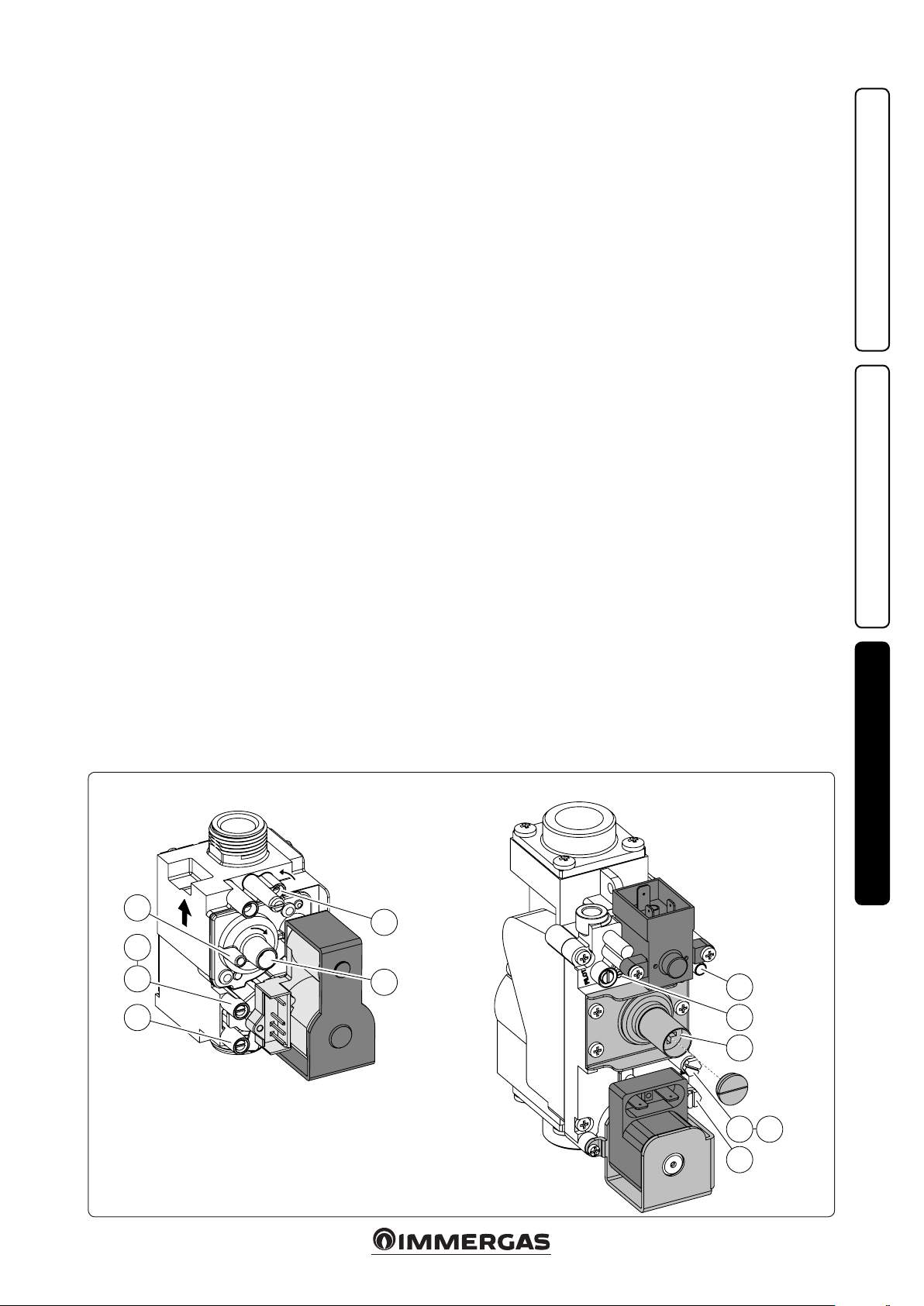
3.10 CONVERTING THE BOILER TO
OTHER TYPES OF GAS.
If the boiler has to be converted to a dierent gas
type to that specied on the data plate, request
the relative conversion kit for quick and easy
conversion.
e gas conversion operation must be carried
out by an authorised company (e.g. Immergas
Aer-Sales Technical Assistance Service).
To convert to another type of gas the following
operations are required:
- disconnect the appliance;
- Change the sleeve with Venturi (det. 21 g.
1-25);
- change the gas nozzle (det. 4 g. 1-25);
- re-power the appliance;
- regulate the maximum heat output by varying
the number of fan revs. (parameter P25 “Max
number of fan revs in CH mode”) according to
par. 3.24;
- regulate the minimum heat output by varying
the number of fan revs. (parameter P26 “Min
number of fan revs in CH mode”) according to
par. 3.24;
- activate the chimney sweep function;
- check the CO2 value on the table in par. 3.25,
especially:
- che ck the CO2 value in the ue with chimney
sweep at 0%;
- che ck the CO2 value in the ue with chimney
sweep at 100%;
- exit the chimney sweep function;
- seal the gas ow rate regulation devices (if
settings are modied);
- after completing the conversion, apply the
sticker, contained in the conversion kit, near
the data-plate. Using an indelible marker pen,
cancel the data relative to the old type of gas.
ese adjustments must be made with reference
to the type of gas used.
3.11 CHECKS FOLLOWING
CONVERSION TO ANOTHER TYPE
OF GAS.
After making sure that transformation was
carried out with the Venturi and a nozzle of
suitable diameter for the type of gas used and
the calibration has been performed at the correct
num. of revs, check that:
- the burner ame is not too high and that it is
stable (does not detach from burner)
- there are no leaks from the gas circuit.
N.B.: all boiler adjustment operations must
be carried out by a qualied technician (e.g.
Immergas Aer-Sales Assistance).
3.12 ADJUSTMENT OF THE AIRGAS
RAT IO.
Calibration of minimum CO
Turn the boiler on and start the chimney sweep
functions at minimum output (0%). To have an
exact value of CO2 the technician must insert
the sampling probe to the bottom of the sample
point, then check that the CO2 value is that
specied in the table in par. 3.25, on the contrary, regulate the screws (3 g. 3-11) (O-Set
regulator). To increase the CO2 value, turn the
adjustment screw (3) in a clockwise direction and
vice versa to decrease it.
Calibration of maximum CO
When you nish the minimum CO2 adjustment,
turn the boiler on and start the chimney sweep
function at the maximum output (100%). To have
an exact value of CO2 the technician must insert
the sampling probe to the bottom of the sample
point, then check that the CO2 value is that specied in the table in par. 3.25, otherwise, adjust
the screw (12 g. 3-11) (gas ow rate regulator).
To increase the CO2 value, turn the adjustment
screw (12) in an anti-clockwise direction and vice
versa to decrease it.
At every adjustment variation on the screw (12)
it is necessary to wait for the boiler to stabilise
itself at the value set (about 30 sec.).
2
.
2
3.13 CH OUTPUT ADJUSTMENT.
If it is necessary to change the CH output, you
will need to adjust the “P08” maximum CH output and “P09” minimum CH output parameters.
To check the regulated heat output value, compare the no. of fan revs with that in the table
(par. 3.24).
3.14 OUTPUT ADJUSTMENT DURING
DHW ONLY IN COMBINATION
WITH AN OPTIONAL EXTERNAL
STORAGE TANK.
If it is necessary to change the DHW output,
you will need to adjust the “P20” maximum
DHW output and “P21” minimum DHW output
parameters.
To check the regulated heat output value, compare the no. of fan revs with that in the table
(par. 3.24).
INSTALLERUSER
+
P1
+
P3
2
1
Key:
1 - Gas valve inlet pressure point
2 - Gas valve outlet pressure point
3 - O/Set adjustment screw
12 - Outlet gas ow rate regulator
12
8222 Gas Valve (Victrix Pro 100 - 120 2ErP)848 Gas Valve (Victrix Pro 80 2ErP)
MAINTENANCE TECHNICIAN
3
P1
12
3
2
1
P3
3-11
35
Page 36

3.15 "CHIMNEY SWEEP" FUNCTION.
is function allows the technician to check
the combustion parameters. Boiler operation in
chimney sweep function can be adjusted to an
output between 0% and 100%.
To enable the function press and hold down “A”
INSTALLERUSER
If there is a common ow probe, it is possible
to activate the chimney sweep function by
pressing buttons “A” and “B” simultaneously. In
this case, the plant pump is activated as well as
the boiler (in the “simple cascade” both boilers
are activated)
e output is adjusted from the + and - DHW
adjustment buttons at a range between 0 and
100%, while using the + and - buttons for CH
adjustment, the percentage changes by 1% each
time they are pressed.
In this state all adjustments are excluded and
only the temperature safety thermostat and the
limit thermostat remain active. When the checks
are nished, disable the function by pressing
and holding down button “A” (Or A + b in the
other case).
If you enable the function when there is no active
request, you will need to wait approximately 30’’
to reach the set output. If you enable the function
when there is an active request, you will need
to wait approximately 3 minutes to reach the
set output.
If you enable the function, you will need to wait
approximately 30’’ to reach the set output (3’ on
the Slave boiler)
3.16 3WAY PUMP ANTIBLOCK
FUNCTION OPTIONAL.
e boiler has a function that starts the pump
and 3-way valve at least once every 24 hours for
the duration of 20 seconds in order to reduce
the risk of the pump becoming blocked due to
prolonged inactivity.
3.17 RADIATORS ANTIFREEZE
MAINTENANCE TECHNICIAN
FUNCTION.
e boiler has a function that makes the pump
start when the system ow water reaches 8 °C. If
the system ow water is at a temperature below
5 °C, the boiler starts to operate until it reaches
approximately 16 °C.
3.18 ANTIHUMIDITY ELECTRODE
FUNCTION.
With cascade installations combined with their
relative ue manifold kits with ue adjusting
devices, humidity may develop on the electrodes,
causing them to fail. Avoid the formation of
humidity by enabling this function (by setting
a value other than 0), which turns the fan on
at the speed set in parameter “P11” (5 minutes
on and 5 minutes o). e function is active
when the burner is o and the ow NTC probe
3-8
temperature reading is greater than 35°C. e
function is disabled when the temperature drops
below 30 °C.
3.19 INLET 0 ÷ 10 V.
e microprocessor has an analogue 0 ÷ 10 V
inlet (“Y” and “Z” terminals g. 1-4) that enables
the boiler to be controlled from the outside.
By setting the “P37” parameter, it is possible
to set-up the inlet by choosing the functioning
mode between temperature set and power set.
e inlet activates a 2 V (minimum) request and
increases it proportionally up to 9.5 V (maximum). e request is deactivated below 1 V.
Notes:
- If “P37” is set at “0”, it is not active when the
boiler is in “stand-by” or “summer” mode.
e calculated set is limited by the “P02” ÷ 20 °C
range. e maximum and minimum temperature
within the set is limited by “P01” and “P32”.
- If “P37” is set on “1” it is always active.
It is not limited by the “P08” and “P09” parameters and does not have priority over the DHW
request.
- Input voltage = -2.5 ÷ 12.5 V
- Input = 200 μA
- Impedance = > 50 KΩ
3.20 FUNCTIONING WITH COMMON
FLOW PROBE.
With a hydraulic circuit breaker, there must be
a common ow probe (with boiler ow probe
functions) and a pump to be connected downstream of the plant.
e probe must be connected to terminals “S1”
and “S2” and parameter “P38” must be set up,
whereas the pump must be connected to terminals “C” and “D”.
If there is a DHW circuit, it can be connected
via an external 3-way to be connected to “IT”,
“IS” and IK terminal, or use a suitable pump to
be connected to “IT” and “IK” terminals. e
DHW circuit has priority over the heating circuit.
Please refer to chart g. 3-13 for the correct
conguration
3.21 AUTODETECTION.
This function enables the association of the
display board to the boiler’s P.C.B. In addition,
in case of “simple cascade” installation, it enables
the detection and combination of cascade boilers.
Turn the boiler on, programme it according to
your needs, press and hold the “-” (g. 2-1 ref. 2)
button down until “AUTO” appears, then press
“RESET” until “bu 1” appears.
3.22 SIMPLE CASCADE MAX. 2
BOILERS
It is possible to create a “simple cascade” by
directly connecting two boilers.
e two boilers turn on alternatively based on
the plant’s requirements.
Carry out the connection as indicated in the
diagram (g. 3-6). With this conguration, there
must be a common ow probe on the thermal
plant, see the chart (g. 3-13) for the possible
options.
In order for the system to recognise the two
boilers, you must activate the Autodetection and
make sure both boilers are on.
ey are associated when “bu 2” appears on
the Master boiler and “SLA 2” appears on the
Slave boiler.
From this moment on, all programming is carried out on the Master boiler, while the “SLA 2”
caption always appears on the Slave boiler, except
in case of anomaly.
e customised parameters of the Master boiler
are automatically replicated on the Slave boiler.
Warning: it is not possible to combine the cascade
and zone regulator to the plant in this case. It is
possible to connect an On/O room thermostat
or use the 0 ÷ 10 V inlet (which must only be
connected to the Master) to control the plant.
N°
boilers
Common ow probe
1 X X No
1 X X Central heating Domestic hot water
1 X X
2 X Not admitted Central heating
2 X X
Parameter “P38” Parameter “P17”
DHW pump (down-
stream the distribu-
tion manifold) = 1
present = 1
Common ow probe
absent = 0
3-way valve = 0
Common ow
probe
Central heating
Domestic hot water
Central heating
Domestic hot water
Boiler ow probe
Central heating
Domestic hot water
Just as
limit thermostat
Just as
limit thermostat
Just as
limit thermostat
36
3-13
Page 37

3.23 YEARLY APPLIANCE CHECK AND
MAINTENANCE.
e following checks and maintenance should
be performed at least once a year.
- Clean the ue side of the heat exchanger.
- Clean the main burner.
- If deposits are detected in the combustion
chamber one must remove them and clean
the exchanger coils using nylon or sorghum
brushes; it is forbidden to use brushes made
of metal or other materials that may damage
the combustion chamber itself.
- Check the integrity of the insulating panels
inside the combustion chamber and if damaged
replace them.
- Visually check for water leaks or oxidation
from/on fittings and traces of condensate
residues inside the sealed chamber.
- Check contents of the condensate drain trap.
- Via the condensate drain cap check that there
are no residues of material that clog condensate
passage; also check that the entire condensate
drainage circuit is clear and ecient.
In the event of obstructions (dirt, sediment,
etc.) with consequent leakage of condensate
in the combustion chamber, one must replace
the insulating panels.
- Check that the burner seal gaskets and the lid
are intact and perfectly ecient, otherwise
replace them. In any case the gaskets must be
replaced at least every two years, regardless of
their state of wear.
- Check that the burner is intact, that it has no
deformations or cuts and that it is properly
xed to the combustion chamber lid; otherwise
it must be replaced.
- Visually check that the water safety drain valve
is not clogged.
- Check that the system static pressure (with
system cold and aer relling the system by
means of the ller cock) is not below 0.5 bar.
- Visually check that the safety and control
devices have not been tampered with and/or
shorted, in particular:
- temperature safety thermostat;
- Check the condition and integrity of the elec-
trical system and in particular:
- electrical power cables must be inside the
fairleads;
- there must be no traces of blackening or
burning.
- Check ignition and operation.
- Check correct calibration of the burner in
central heating phase.
- Check the operation of the appliance control
and adjustment devices and in particular:
- intervention of the main electrical switch on
the boiler;
- system regulation probes intervention;
- Check sealing eciency of the gas circuit and
the internal system.
- Check the intervention of the device against
no gas ionisation ame control. e relative
intervention time must be less than 10 seconds.
N.B.: in addition to yearly maintenance, one
must also check the thermal system, with frequency and procedures that comply with the
indications of the technical regulations in force.
INSTALLERUSER
MAINTENANCE TECHNICIAN
37
Page 38

3.24 CASING REMOVAL.
To facilitate boiler maintenance the casing can
be completely removed as follows:
- take the two screws out (3) from the bottom of
the front (2);
- take the front down (2) by gripping its bottom
handle, then pulling it towards yourself to detach it from the central hooks, and then slide
it downwards;
- take the two clamping screws out (4) from the
control panel, with their rings (5);
INSTALLERUSER
- press the two side hooks (7) and tilt the control
panel (6);
- remove the lower grid (8) by loosening the 4
screws (9);
- at this point, if necessary, you can take down
the protective cover (10) and side panels (12);
- take the cover down (10) by removing the
relative screws (11);
- take down the two side panels (12) by removing
the front screws (13) and unhooking the panels
(ref. A g. 3-15).
MAINTENANCE TECHNICIAN
2
1
5
4
3
3
3-14
38
Page 39
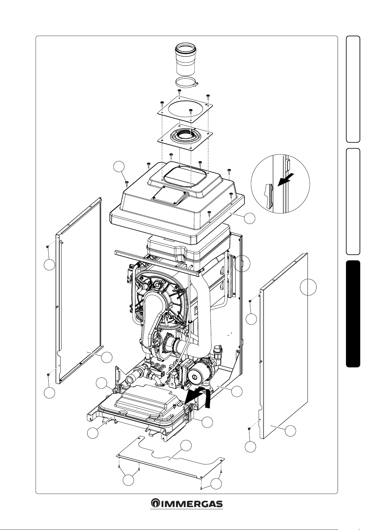
13
11
10
A
Ref. A
Rif. A
INSTALLERUSER
13
A
13
12
7
1
7
6
8
13
12
MAINTENANCE TECHNICIAN
9
39
9
3-15
Page 40
3.25 VARIABLE HEAT OUTPUT.
Victrix Pro 80 2ErP.
METHANE (G20) PROPANE (G31)
INSTALLERUSER
MAINTENANCE TECHNICIAN
HEAT OUTPUT HEAT OUTPUT
(kW) (kcal/h) (m
BURNER GAS FLOW
RAT E
3
/h) (n°) (kg/h) (n°)
REVS
FAN
BURNER GAS FLOW
RAT E
73.0 62780 7.96 6600 5.85 6550
71.0 61060 7.74 6420 5.68 6360
69.0 59340 7.52 6240 5.52 6170
67.0 57620 7.30 6070 5.35 5990
65.0 55900 7.07 5890 5.19 5800
63.0 54180 6.85 5720 5.03 5620
61.0 52460 6.63 5550 4.87 5440
59.0 50740 6.42 5380 4.71 5270
57.0 49020 6.20 5210 4.55 5090
55.0 47300 5.98 5040 4.39 4920
53.0 45580 5.76 4880 4.23 4750
51.0 43860 5.55 4710 4.07 4580
49.0 42140 5.33 4550 3.91 4410
47.0 40420 5.11 4390 3.75 4250
45.0 38700 4.90 4230 3.60 4080
43.0 36980 4.68 4070 3.44 3920
41.0 35260 4.47 3910 3.28 3760
39.0 33540 4.25 3750 3.12 3600
37.0 31820 4.04 3600 2.96 3450
35.0 30100 3.82 3440 2.81 3290
33.0 28380 3.61 3290 2.65 3130
31.0 26660 3.39 3130 2.49 2980
29.0 24940 3.18 2980 2.33 2830
27.0 23220 2.96 2830 2.17 2680
25.0 21500 2.75 2680 2.02 2530
23.0 19780 2.53 2520 1.86 2380
21.0 18060 2.31 2370 1.70 2230
19.0 16340 2.10 2220 1.54 2090
17.0 14620 1.88 2070 1.38 1940
15.0 12900 1.66 1930 1.22 1800
13.0 11180 1.44 1780 1.06 1660
11.0 9460 1.22 1630 0.90 1520
9.0 7740 1.00 1480 0.74 1380
7.2 6192 0.80 1350 0.59 1250
REVS
FAN
N.B.
- e power data provided in the table is obtained with 0.5 m long intake/exhaust pipe.
- Gas ow rates refer to heating output below a
temperature of 15°C and pressure of 1013 mbar.
- Burner pressure values refer to use of gas at
15°C.
- e number of revs for the fan on the display
is expressed in revs / 50 (Ex.: 1000 revs = 20).
40
Page 41
Victrix Pro 100 2ErP.
METHANE (G20) PROPANE (G31)
HEAT OUTPUT HEAT OUTPUT
(kW) (kcal/h) (m
BURNER GAS FLOW
RAT E
3
/h) (n°) (kg/h) (n°)
REVS
FAN
BURNER GAS FLOW
RAT E
90.0 77400 9.77 6700 7.17 6350
87.0 74820 9.44 6470 6.93 6140
84.0 72240 9.11 6230 6.68 5930
81.0 69660 8.78 6000 6.44 5730
78.0 67080 8.45 5780 6.20 5530
75.0 64500 8.12 5560 5.96 5320
72.0 61920 7.79 5340 5.72 5130
69.0 59340 7.47 5120 5.48 4930
66.0 56760 7.14 4910 5.24 4730
63.0 54180 6.82 4700 5.00 4540
60.0 51600 6.49 4490 4.77 4340
57.0 49020 6.17 4280 4.53 4150
54.0 46440 5.85 4080 4.29 3960
51.0 43860 5.52 3880 4.05 3770
48.0 41280 5.20 3680 3.82 3580
45.0 38700 4.88 3480 3.58 3400
42.0 36120 4.56 3290 3.34 3210
39.0 33540 4.23 3090 3.11 3030
36.0 30960 3.91 2900 2.87 2840
33.0 28380 3.59 2710 2.63 2660
30.0 25800 3.27 2530 2.40 2480
27.0 23220 2.94 2340 2.16 2300
24.0 20640 2.62 2160 1.92 2120
21.0 18060 2.30 1980 1.68 1940
18.0 15480 1.97 1800 1.45 1760
15.0 12900 1.64 1630 1.21 1580
12.0 10320 1.32 1450 0.97 1400
9.4 8084 1.03 1300 0.76 1250
REVS
FAN
INSTALLERUSER
N.B.
- e power data provided in the table is obtained with 0.5 m long intake/exhaust pipe.
- Gas ow rates refer to heating output below a
temperature of 15°C and pressure of 1013 mbar.
- Burner pressure values refer to use of gas at
15°C.
- e number of revs for the fan on the display
is expressed in revs / 50 (Ex.: 1000 revs = 20).
MAINTENANCE TECHNICIAN
41
Page 42

Victrix Pro 120 2ErP.
METHANE (G20) PROPANE (G31)
HEAT OUTPUT HEAT OUTPUT
(kW) (kcal/h) (m
111.0 95460 12.07 7000 8.86 7000
108.0 92880 11.74 6810 8.62 6800
INSTALLERUSER
105.0 90300 11.41 6620 8.37 6600
102.0 87720 11.08 6430 8.13 6400
99.0 85140 10.75 6240 7.89 6200
96.0 82560 10.42 6050 7.65 6010
93.0 79980 10.09 5870 7.40 5810
90.0 77400 9.76 5680 7.16 5620
87.0 74820 9.43 5500 6.92 5440
84.0 72240 9.10 5320 6.68 5250
81.0 69660 8.78 5140 6.44 5070
78.0 67080 8.45 4970 6.20 4880
75.0 64500 8.13 4790 5.97 4700
72.0 61920 7.80 4620 5.73 4530
69.0 59340 7.48 4440 5.49 4350
66.0 56760 7.15 4270 5.25 4170
63.0 54180 6.83 4100 5.01 4000
60.0 51600 6.51 3930 4.78 3830
57.0 49020 6.18 3760 4.54 3660
54.0 46440 5.86 3590 4.30 3490
51.0 43860 5.54 3430 4.06 3330
48.0 41280 5.21 3260 3.83 3160
45.0 38700 4.89 3100 3.59 3000
42.0 36120 4.57 2930 3.35 2840
39.0 33540 4.24 2770 3.12 2680
36.0 30960 3.92 2610 2.88 2520
33.0 28380 3.60 2450 2.64 2360
30.0 25800 3.27 2290 2.40 2200
27.0 23220 2.95 2130 2.16 2050
24.0 20640 2.62 1970 1.92 1900
21.0 18060 2.30 1820 1.69 1750
18.0 15480 1.97 1660 1.45 1600
15.0 12900 1.64 1510 1.21 1450
12.0 10320 1.32 1350 0.97 1300
MAINTENANCE TECHNICIAN
11.0 9460 1.21 1300 0.89 1250
N.B.
- e power data provided in the table is obtained with 0.5 m long intake/exhaust pipe.
- Gas ow rates refer to heating output below a
temperature of 15°C and pressure of 1013 mbar.
- Burner pressure values refer to use of gas at
15°C.
- e number of revs for the fan on the display
is expressed in revs / 50 (Ex.: 1000 revs = 20).
BURNER GAS FLOW
RAT E
3
/h) (n°) (kg/h) (n°)
REVS
FAN
BURNER GAS FLOW
RAT E
REVS
FAN
42
Page 43

3.26 COMBUSTION PARAMETERS.
Victrix Pro 80 2ErP
G20 G31
Gas nozzle diameter mm 12.70 8.50
Supply pressure mbar (mm H
O) 20 (204) 37 (377)
2
Flue ow rate at nominal heat output kg/h 114 120
Flue ow rate at min heat output kg/h 13 13
at Q. Nom./Min. % 9.95 / 8.95 10.60 / 9.75
CO
2
CO with 0% O
at 0% of O2 at Q. Nom./Min. mg/kWh 34 / 1 65 / 6
NO
X
at Nom./Min. Q. Nom./Min. ppm 233 / 4 175 / 4
2
Flue temperature at nominal output °C 62 61
Flue temperature at minimum output °C 43 42
Victrix Pro 100 2ErP
Gas nozzle diameter mm 11.30 8.40
Supply pressure mbar (mm H
O) 20 (204) 37 (377)
2
Flue ow rate at nominal heat output kg/h 146 148
Flue ow rate at min heat output kg/h 16 16
at Q. Nom./Min. % 9.40 / 9.00 10.60 / 10.10
CO
2
CO with 0% O
at 0% of O2 at Q. Nom./Min. mg/kWh 62 / 8 67 / 10
NO
X
at Nom./Min. Q. Nom./Min. ppm 210 / 5 230/ 1
2
Flue temperature at nominal output °C 53 54
Flue temperature at minimum output °C 45 45
Victrix Pro 120 2ErP
Gas nozzle diameter mm 16.50 9.70
Supply pressure mbar (mm H
O) 20 (204) 37 (377)
2
Flue ow rate at nominal heat output kg/h 174 183
Flue ow rate at min heat output kg/h 19 19
at Q. Nom./Min. % 9.80 / 9.00 10.60 / 10.00
CO
2
CO with 0% O
at 0% of O2 at Q. Nom./Min. mg/kWh 95 / 9 77 / 13
NO
X
at Nom./Min. Q. Nom./Min. ppm 257 / 1 220 / 1
2
Flue temperature at nominal output °C 56 56
Flue temperature at minimum output °C 46 46
INSTALLERUSER
43
MAINTENANCE TECHNICIAN
Page 44
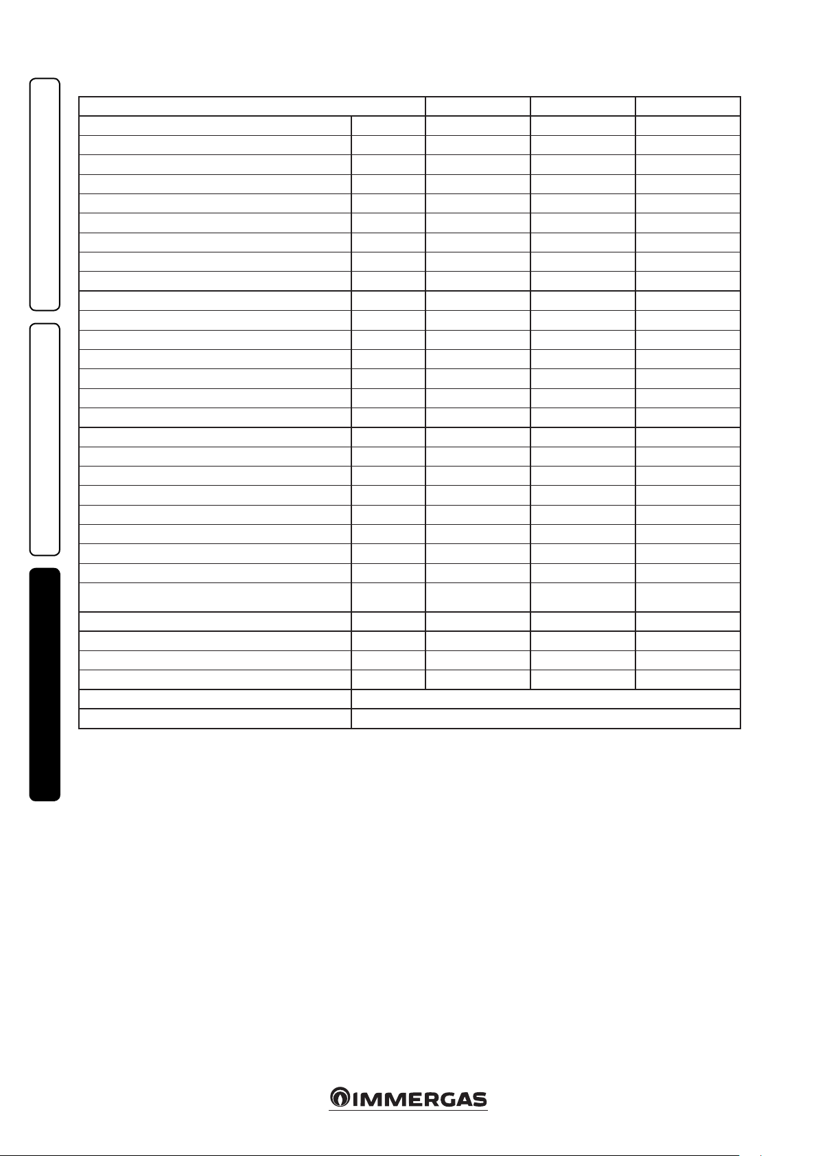
3.27 TECHNICAL DATA.
Victrix Pro 80 2ErP Victrix Pro 100 2ErP Victrix Pro 120 2ErP
Nominal heat input kW (kcal/h) 75.3 (64722) 92.3 (79385) 114.1 (98109)
Minimum heat input kW (kcal/h) 7.6 (6532) 9.8 (8401) 11.4 (9813)
Nominal heat output (useful) kW (kcal/h) 73.0 (62780) 90.0 (77400) 111.0 ( 95460)
Minimum heat output (useful) kW (kcal/h) 7.2 (6192) 9.4 (8084) 11.0 (9460)
Eective thermal eciency 80/60 Nom./Min. % 97.0 / 94.8 97.5 / 96.2 97.3 / 96.4
Eective thermal eciency 50/30 Nom./Min. % 106.6 / 106.9 107.0 / 107.4 106.7 / 107.2
INSTALLERUSER
Eective thermal eciency 40/30 Nom./Min. % 107.3 / 107.2 107.4 / 107.6 107.2 / 107.5
Heat loss at casing with burner On/O (80-60°C) % 0.34 / 0.80 0.41 / 0.60 0.28 / 0.70
Heat loss at ue with burner On/O (80-60°C) % 0.01 / 2.2 0.01 / 1.9 0.01 / 2.0
Central heating circuit max. operating pressure bar 4.4 4.4 4.4
Central heating circuit max. operating temperature °C 90 90 90
Adjustable central heating temperature °C 20 - 85 20 - 85 20 - 85
Head available with 1000 l/h ow rate kPa (m H
O) 81.4 (8.30) 116.5 (11.88) 116.5 (11.88)
2
Weight of full boiler kg 85.0 106.0 114.2
Weight of empty boiler kg 81.0 95.9 102.5
Boiler water content l 4.0 10.1 11.7
Electrical connection V/Hz 230/50 230/50 230/50
Nominal absorption A 1.5 2.3 2.5
Installed electric output W 195 345 385
Pump consumption W 82 183 186
Fan power consumption W 100 154 184
Equipment electrical system protection - IPX5D IPX5D IPX5D
Max. operating room temperature °C +50 +50 +50
Min. operating room temperature °C -5 -5 -5
Min. operating room temperature with anti-freeze kit
(Optional)
Flue gas max. temperature °C 75
class -
NO
X
Weighted NO
X
°C -15 -15 -15
75 75
6
6 6
mg/kWh 25.0 20.0 33.0
Weighted CO mg/kWh 16.0 12.0 18.0
Type of appliance C13 / C33 / C63 / B23p / B33 / B53p
Category II2H3P
- Flue temperature values refer to an air inlet
temperature of 15°C and ow temperature of
50°C.
MAINTENANCE TECHNICIAN
- The maximum sound level emitted during
boiler operation is < 55dBA. e sound level
value is referred to semianechoic chamber tests
with boiler operating at max. heat output, with
extension of ue gas exhaust system according
to product standards.
44
Page 45

3.28 KEY FOR DATA PLATE.
Md Cod. Md
Sr N° CHK Cod. PIN
Type
Qnw/Qn min. Qnw/Qn max.
Pn min. Pn max.
PMS PMW D TM
x Class
NO
N.B.: the technical data is provided on the data plate on the boiler
ENG
Md Model
Cod. Md Model code
Sr N° Serial Number
CHK Check
Cod. PIN PIN code
Typ e appliance conguration
nw min. Minimum DHW heat input
Q
n min. CH minimum heat input
Q
nw max. DHW maximum heat input
Q
Qn max. CH maximum heat input
n min. Minimum heat output
P
n max. Maximum heat output
P
PMS Maximum system pressure
PMW Maximum domestic hot water pressure
D Specic ow rate
TM Maximum operating temperature
x Class NOx Class
NO
CONDENSING Condensing boiler
(ref. CEN TR 1749)
INSTALLERUSER
CONDENSING
45
MAINTENANCE TECHNICIAN
Page 46

3.29 TECHNICAL PARAMETERS FOR MIXED BOILERS IN COMPLIANCE WITH REGULATION 813/2013.
e yields in the following tables refer to the higher heating value.
Model/s: Victrix Pro 80 2ErP
Condensing Boilers: SI
Low temperature boiler: NO
Boiler type B1: NO
Co-generation appliance for central heating: NO Fitted with supplementary heating system: NO
Mixed heating appliance: SI
Element Symbol Val ue Unit Element Symbol Va lu e Unit
Nominal heat output P
n
73 kW
Seasonal energy eciency of central
heating
η
s
91 %
For central heating only and mixed boilers: useful heat output For central heating only and mixed boilers: useful eciency
At nominal heat output in high tempera-
ture mode (*)
At 30% of nominal heat output in a low
temperature mode (**)
4
1
73.0 kW
21.9 kW
P
P
At nominal heat output in high temperature mode (*)
At 30% of nominal heat output in a low
temperature mode (**)
η
η
4
1
87.5 %
96.0 %
Auxiliary electricity consumption Other items
At full load el
At partial load el
In standby mode P
0.119 kW Heat loss in standby P
max
0.024 kW Ignition burner energy consumption P
min
0.004 kW Emissions of nitrogen oxides NO
SB
stby
ign
X
0.143 kW
0.000 kW
22
kWh
For mixed central heating appliances
mg /
Stated load prole Domestic hot water production eciency η
Daily electrical power consumption Q
elec
kWh Daily gas consumption Q
WH
fuel
%
kWh
Contact information IMMERGAS S.p.A. VIA CISA LIGURE, 95 - 42041 BRESCELLO (RE) ITALY
(*) High temperature mode means 60°C on return and 80°C on ow.
(**) Low temperature mode for condensation Boilers means 30°C , for low temperature boilers 37°C and for other appliances 50°C of return temperature.
Model/s: Victrix Pro 100 2ErP
Condensing Boilers: SI
Low temperature boiler: NO
Boiler type B1: NO
Co-generation appliance for central heating: NO Fitted with supplementary heating system: NO
Mixed heating appliance: SI
Element Symbol Val ue Unit Element Symbol Va lu e Unit
Nominal heat output P
n
90 kW
Seasonal energy eciency of central
heating
η
s
92 %
For central heating only and mixed boilers: useful heat output For central heating only and mixed boilers: useful eciency
At nominal heat output in high tempera-
ture mode (*)
At 30% of nominal heat output in a low
temperature mode (**)
4
1
90.0 kW
27.0 kW
P
P
At nominal heat output in high temperature mode (*)
At 30% of nominal heat output in a low
temperature mode (**)
η
η
4
1
88.0 %
96.8 %
Auxiliary electricity consumption Other items
At full load el
At partial load el
In standby mode P
0.143 kW Heat loss in standby P
max
0.017 kW Ignition burner energy consumption P
min
0.005 kW Emissions of nitrogen oxides NO
SB
stby
ign
X
0.145 kW
0.000 kW
18
mg /
kWh
For mixed central heating appliances
Stated load prole Domestic hot water production eciency η
Daily electrical power consumption Q
elec
kWh Daily gas consumption Q
WH
fuel
%
kWh
Contact information IMMERGAS S.p.A. VIA CISA LIGURE, 95 - 42041 BRESCELLO (RE) ITALY
(*) High temperature mode means 60°C on return and 80°C on ow.
(**) Low temperature mode for condensation Boilers means 30°C , for low temperature boilers 37°C and for other appliances 50°C of return temperature.
Page 47

Model/s: Victrix Pro 120 2ErP
Condensing Boilers: SI
Low temperature boiler: NO
Boiler type B1: NO
Co-generation appliance for central heating: NO Fitted with supplementary heating system: NO
Mixed heating appliance: SI
Element Symbol Val ue Unit Element Symbol Va lu e Unit
Nominal heat output P
n
111 kW
Seasonal energy eciency of central
heating
η
s
92 %
For central heating only and mixed boilers: useful heat output For central heating only and mixed boilers: useful eciency
At nominal heat output in high tempera-
ture mode (*)
At 30% of nominal heat output in a low
temperature mode (**)
P
4
P
1
111.0 kW
33.3 kW
At nominal heat output in high temperature mode (*)
At 30% of nominal heat output in a low
temperature mode (**)
η
η
4
1
87.9 %
96.5 %
Auxiliary electricity consumption Other items
At full load el
At partial load el
In standby mode P
0.190 kW Heat loss in standby P
max
0.019 kW Ignition burner energy consumption P
min
0.004 kW Emissions of nitrogen oxides NO
SB
stby
ign
X
0.168 kW
0.000 kW
28
mg /
kWh
For mixed central heating appliances
Stated load prole Domestic hot water production eciency η
Daily electrical power consumption Q
elec
kWh Daily gas consumption Q
WH
fuel
%
kWh
Contact information IMMERGAS S.p.A. VIA CISA LIGURE, 95 - 42041 BRESCELLO (RE) ITALY
(*) High temperature mode means 60°C on return and 80°C on ow.
(**) Low temperature mode for condensation Boilers means 30°C , for low temperature boilers 37°C and for other appliances 50°C of return temperature.
Page 48
immergas.com
Immergas S.p.A.
42041 Brescello (RE) - Italy
Tel. 0522.689011
Fax 0522.680617
Certied company ISO 9001
is instruction booklet is made of ecological paper Cod. 1.041665ENG - rev. ST.003520/000 - 08/18 - Inglese per IRLANDA (IE)
 Loading...