

Page 1
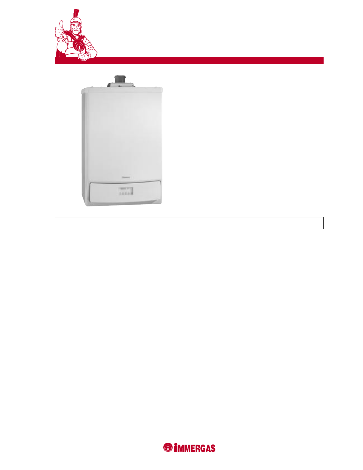
Wall mounted condensing boilers with low NOx
VICTRIX 50
1
1 SPECIFICATIONS
50 kW (43,000 kcal/h) wall-mounted premixed condensing boiler
with sealed or open chamber, forced draught, high efciency and
forced circulation.
Approved for installation in both heating plants and outside buildings. Can be used in two congurations:
Open chamber and forced draught (appliance type B23/ B
33
)
- Does not need any additional kit as it leaves the factory in this
conguration.
Sealed chamber and forced draught (appliance type C13/C33/C63)
- if installed using the vertical or horizontal concentric kits.
The generator consists of:
• combustion system of the total premixing type with cylindricel
multigas burner made of steel, complete with ignition electrodes
and ionizing monitoring probe;
• pneumatic type gas valve with double shutter;
• primary gas/water exchanger with coil made of AISI 316L stainless
steel;
• combustion chamber in stainless steel insulated on the inside with
ceramic panels;
• fumes extraction fan with electronically variable speed;
• condensation disposal circuit including syphon and exible drain
hose;
• hydraulics consisting of a delivery manifold, primary circuit
pressure switch, circulation pump including automatic air venting
valve;
• 4 bar system safety valve (ISPESL approved), pressure gauge for
the heating system;
• overtemperature safety thermostat;
• control panel equipped with electronic board with microprocessor
and innite ame modulation for the heating process plus P.I.D.
monitoring, modulation ranging from 10.0 to 50.0 kW (from 8,600
to 43,000 kcal/h);
• system delivery regulating probe;
• system return regulating probe;
• heating delivery temperature with 20 to 85°C factory setting;
• ignition delayer during the heating phase, antifreeze protection,
pump anti-blocking system, chinmey-sweep function;
• the boiler operating parameters can be entered and regulated by
means of keys while the status and operating modes are shown
on the 4-digit display;
• autodiagnosis system with digital display of the temperature,
the operating status and error codes on the permanently visible
display;
• IPX5D electrical insulation degree;
• pre-engineered for connection of the Series Regulator and external
probe;
• pre-engineered for connection of an external three-way valve for
use with a separate water heater in order to produce domestic hot
water;
• pre-engineered for operation in series (up to 3 generators);
• pre-engineered for installation of the ISPESL-approved safety
stub pipe;
• can be used with the Ø 80 mm hose pipe connecting system.
Supplied complete with traps for combustion analysis, bottom
protection grille and gas on-off cock.
Natural gas and L.P.G. fuelled Class II
2H3+
appliance. CE marking.
The following model is available:
• VICTRIX 50 code 3.015276
NOTE: to correctly install the boiler, use the "Green series" Immergas
air intake/fumes exhaust kit dedicated to the VICTRIX 50 boiler in
both the single and series (bank) congurations.
VICTRIX 50 is the new wall-mounted condensing boiler for
room heating alone. It is pre-engineered for operation both
independently and in series (up to 3 appliances connected),
with the advantage of providing a globally higher efciency at lower running costs. Condensing technology allows
particularly high efciency ratings to be achieved (4 stars,
as established by Directive 92/42/EEC). VICTRIX 50's high
power is ideal when it comes to heating domestic systems
that have to deal with large volumes (semi-detached houses,
small condominiums and apartment blocks) and for commercial and industrial uses. If a single boiler is installed, an
external three-way valve can be connected so as to use it
with a separate water heater and produce domestic hot water. A hydraulic manifold can also be connected to boost the
circulation in the system, thus making it versatile and quick
to install. When operation is in series, several distribution
manifolds can be connected by means of threaded mechanisms. The special environment-friendly burner guarantees
particularly low polluting emissions (the boiler belongs to the
most environment-friendly class established by the European
standards, i.e. class 5).
Page 2
2
VICTRIX 50
3
VICTRIX 50
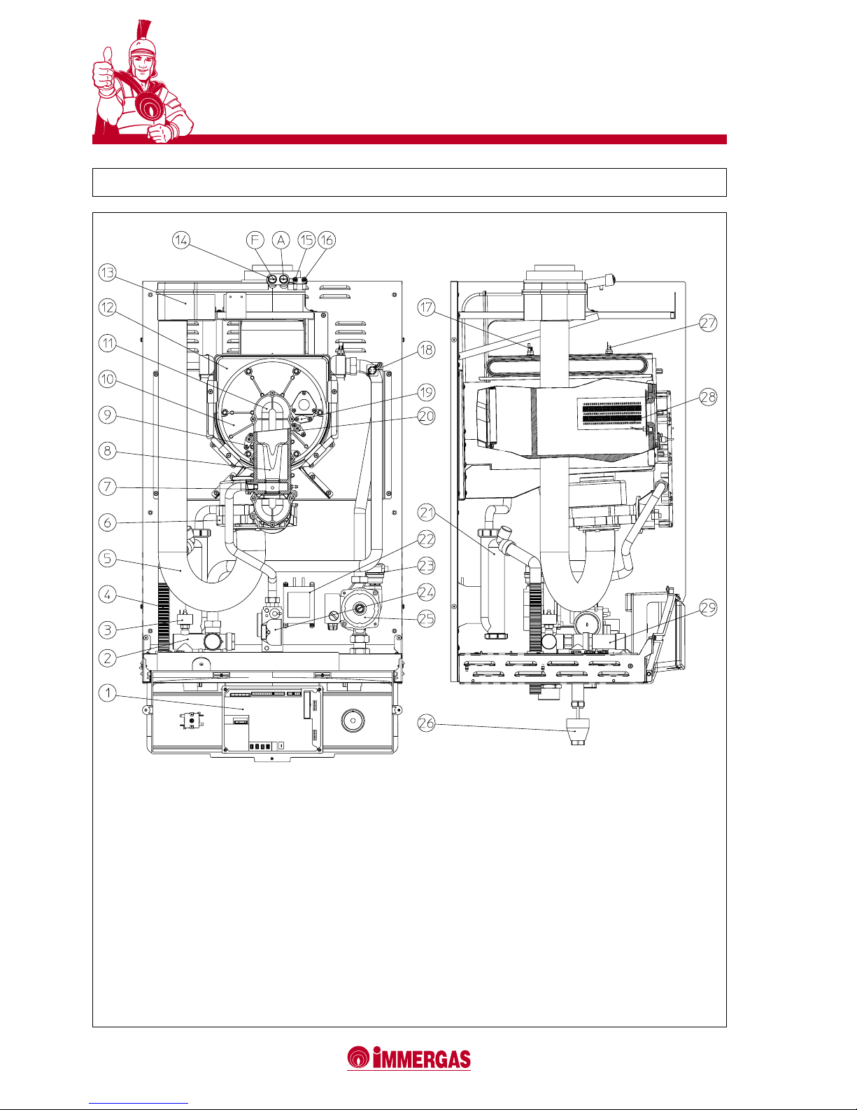
LEGEND:
1 - Electronic board
2 - Delivery manifold
3 - System pressure switch
4 - Condensation drain pipe
5 - Air intake pipe
6 - Air fan
7 - Gas nozzle
8 - Venturi
9 - Detection electrode
10 - Cover of condensing module
11 - Sleeve with Venturi housing
12 - Condensing module
13 - Draught diverter
14 - Intakes (air A) - (fumes F)
15 - Positive signal pressure point
16 - Negative signal pressure point
17 - System return regulating NTC probe
18 - Overtemperature safety thermostat
19 - Dummy electrode
20 - Ignition plug
21 - Condensate syphon
22 - Current transformer
23 - Air venting valve
24 - Gas valve
25 - Circolulation pump
26 - Drain funnel
27 - System delivery regulating NTC probe
28 - Burner
29 - 4-bar safety valve
2 MAIN COMPONENTS
Page 3
3
VICTRIX 50
Upper casing line
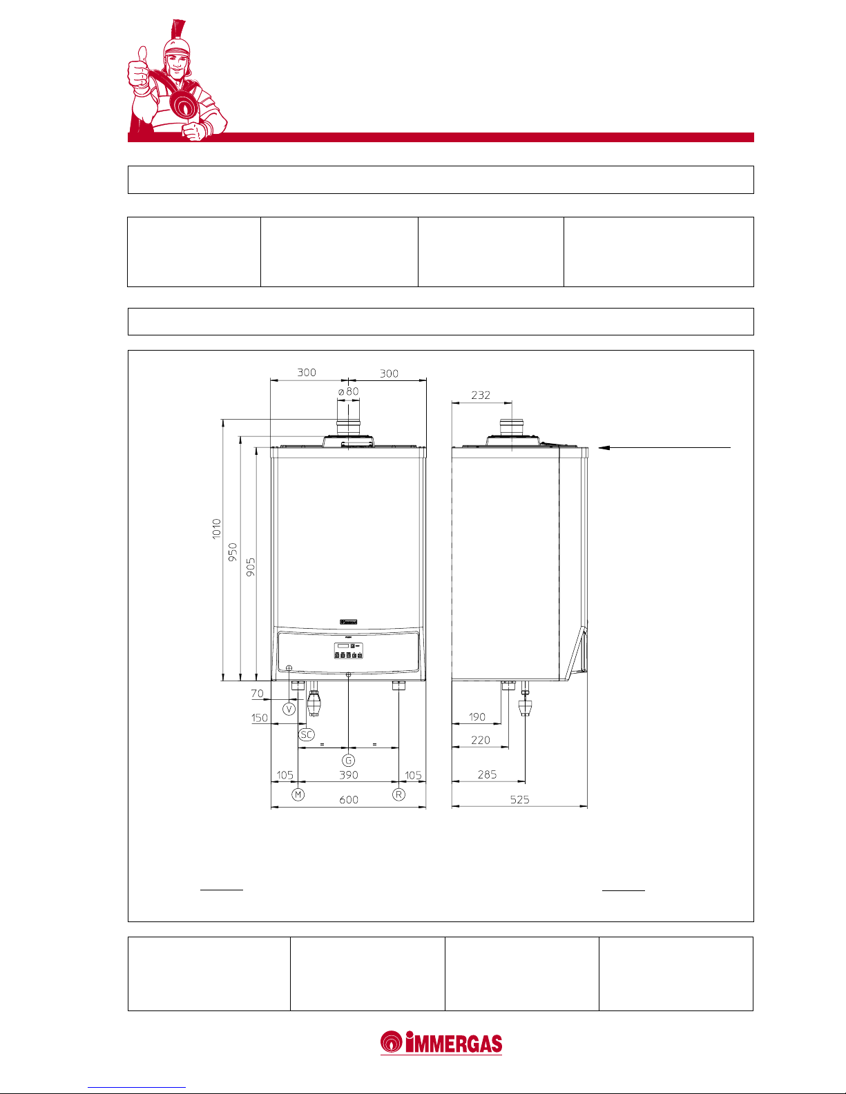
3 MAIN DIMENSIONS
3.1 CONNECTIONS
SC = Condensation discharge
Distance between upper casing line and Ø 80 outlet
elbow: 170 mm
Distance between upper casing line and Ø 80/125
concentric inlet/outlet elbow: 200 mm
Model
VICTRIX 50
System delivery
M
1" 1/2
System return
R
1" 1/2
Gas supply
G
3/4"
Model
VICTRIX 50
Height mm
950
Width mm
600
Depth mm
525
Page 4
4
VICTRIX 50
5
VICTRIX 50
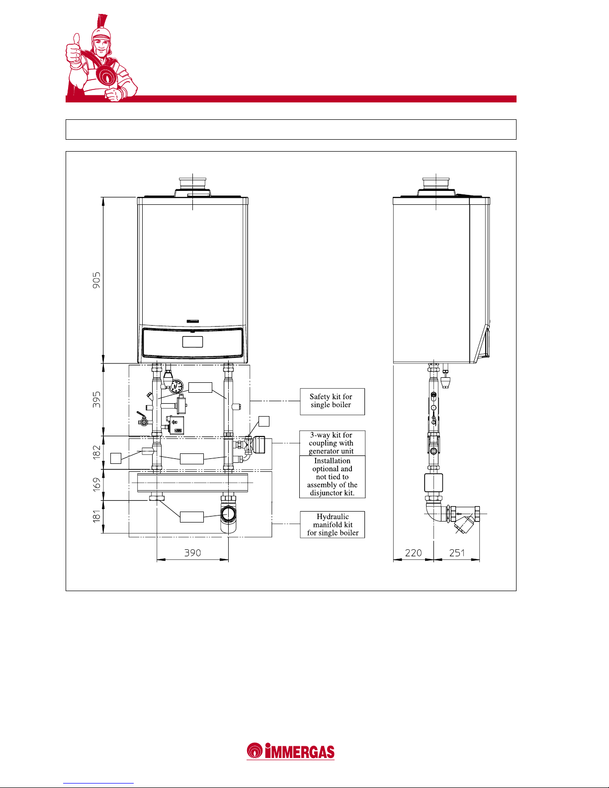
4 DIMENSIONS AND WET CONNECTIONS (OPTIONAL) WITH A SINGLE BOILER
NOTE: Unlike the appliance, the ISPESL safety kit and the
three-way valve kit (electric valve motor) have the IPX4D
electrical protection degree. If the appliance is installed outdoors, these safety devices and components must therefore
be adequately protected.
Immergas declines all liability if the installer fails to use the
genuine ISPESL-approved devices and kits manufactured by
Immergas, or uses them improperly.
The sensitive parts of the automatic thermal regulating and
blocking switches and those of the thermometer (not part of
the standard supply provided with the generator) must be
M
R
positioned as described in the installation instructions, in
compliance with the provisions given in the "R" le.
For ISPESL planning reasons, an ISPESL-approved pressure
gauge must be added when the Immergas safety kit is installed (as part of the standard supply, the boiler comes already
equipped with an ISPESL-approved 4-bar safety valve and
drain funnel).
The system return is pre-engineered with an expansion tank
connection.
1" 1/2
1" 1/2
1"
2" 1/2
1"
Page 5
5
VICTRIX 50
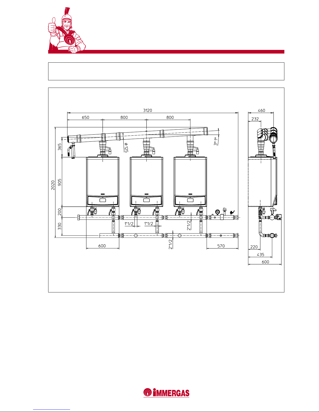
5 DIMENSIONS AND WET CONNECTIONS (OPTIONAL) WITH BOILERS IN SERIES
(UP TO THREE APPLIANCES)
NOTE: Unlike the appliance, the ISPESL safety kit has the
IPX4D electrical protection degree. If the appliance is installed
outdoors, these safety devices must therefore be adequately
protected.
Immergas declines all liability if the installer fails to use the
genuine ISPESL-approved devices and kits manufactured by
Immergas, or uses them improperly.
The sensitive parts of the automatic thermal regulating and
blocking switches and those of the thermometer (not part of
the standard supply provided with the generator) must be
positioned as described in the installation instructions, in
compliance with the provisions given in the "R" le.
For ISPESL planning reasons, an ISPESL-approved pressure
gauge must be added when the Immergas safety kit is instal-
led (as part of the standard supply, the boiler comes already
equipped with an ISPESL-approved 4-bar safety valve and
drain funnel).
The system return is pre-engineered with an expansion tank
connection.
The modular generators, or ones installed in the series
conguration (bank) with the genuine Immergas hydraulic
manifold kit, must be considered a single appliance which
will have the serial number (factory number) of the generator
nearest to the ISPESL safety device.
The hydraulic manifolds are equipped with a check valve
installed on the return pipe and system on-off cocks on the
delivery and return pipes of each generator.
R
M
Page 6
6
VICTRIX 50
7
VICTRIX 50
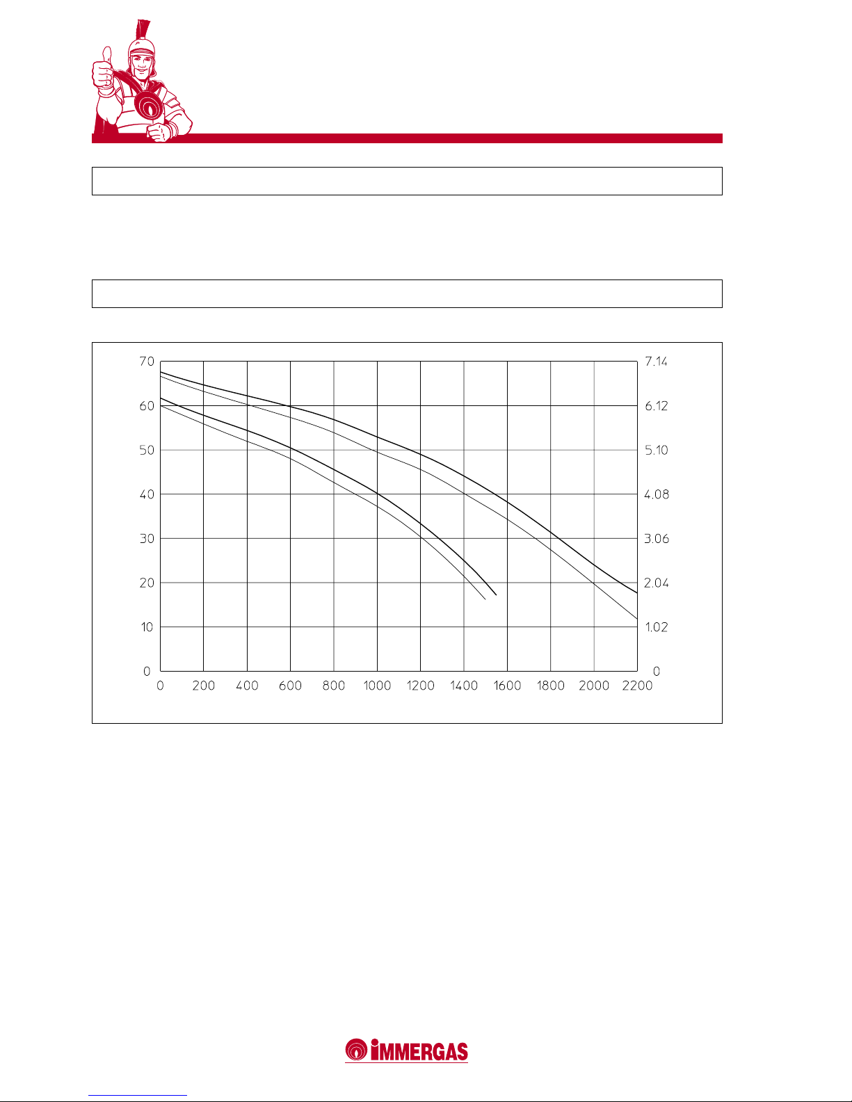
6 CIRCULATOR HEAD AND FLOW RATE GRAPH
VICTRIX 50 boilers are supplied with built-in circulator and
three-position electric speed governor.
The circulator is the single-phase type (230 V - 50 Hz) are co-
mes already equipped with condenser. In new systems (single
pipe and modules), it is advisable to use the circulator pump
at top speed to obtain optimum operation from the boiler.
A = Available head at top speed with single boiler
B = Available head at second speed with single boiler
C = Available head at top speed with check valve for boilers in series (bank)
D = Available head at second speed with check valve for boilers in series (bank)
DYL 63-15
Head (kPa)
A
Flow rate l/h
C
B
6.1 VICTRIX 50 CIRCULATOR
D
Head wc.)
Page 7
7
VICTRIX 50
7 THERMOREGULATION SYSTEMS (OPTIONAL)
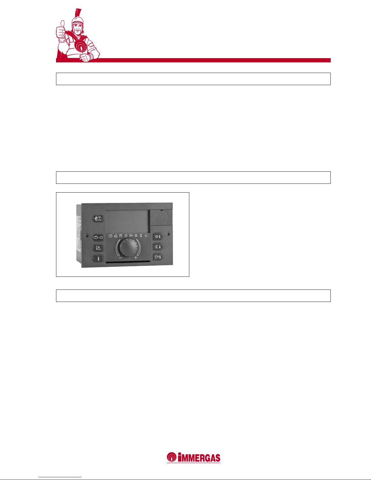
8 SERIES AND ZONE REGULATOR (CODE 3.015244)
Single modular generators or ones installed in series need an
adequate thermoregulation system able to dialogue with the
boiler in a simple way and meet the most varied operating
requirements.
This is why the VICTRIX 50 generator can be tted with a
series of accessories able to optimize the climatic adjustments
made to the entire system.
In short, VICTRIX 50 can be installed with two types of
system:
• In series (with the system divided into one or more zones),
using the series regulator with either the zone controller or
modulating ambient thermostat that regulates the heat in
the individual zones.
• Individually (with the system divided into zones) using the
series regulator with either the zone controller or modulating
ambient thermostat that regulates the heat in the individual
zones. A commercially available timer-thermostat can be
used if there is only one zone.
The Series and zone regulator allows the user to control, monitor and program the operating sequence of the generators
connected. The regulator can be set-up and programmed
using parameters that guarantee ideal temperature conditions at all times of the day and night and throughout every
day of the week for both the heating system and domestic
hot water system (when VICTRIX 50 is used in conjunction
with a water heater). The series regulator can be tted into a
support afxed to a wall.
8.1 SPECIFICATIONS
The electrical connections are made with 2 wires powered at
230V (1.5 mm2 ) in diameter.
2 BUS data cables up to 50 meters in length are used to
connect to the boiler, allowing the device to:
• control up to three zones (2 of which mixed if necessary)
and a separate water heater unit. Since up to 5 series regulators can be installed (of which only one, the so-called
Master, will be connected to the boiler board), systems with
up to a total 15 zones (of which 10 mixed if necessary) and
5 separate water heater units can be controlled;
• enter two ambient temperature values, one for the daytime
(comfort temp.) and one for the night (lower temp.);
• control the temperature of the domestic hot water (in
conjunction with a water heater Unit);
• select the operating mode for the heating and hot water
production functions of each individual hydraulic circuit:
- comfort temperature mode,
- low temperature mode,
- adjustable antifreeze temperature mode;
• control the boiler delivery temperature according to the outdoor temperature (in conjunction with the external probe),
with climatic curve settings;
• obtain information about the system:
- temperature of the system,
- operating mode,
- meter data,
- timer program,
- pump operating status,
- variable input values and operation;
• enter the operating parameters:
- operating times,
- operating mode,
- domestic hot water,
- direct, mixed 1, mixed 2 circuits,
- date and time;
• display operating faults with their relative error codes by
means of the check-control system;
• display the date, time, day of the week and temperature of
the generator.
Page 8
8
VICTRIX 50
9
VICTRIX 50
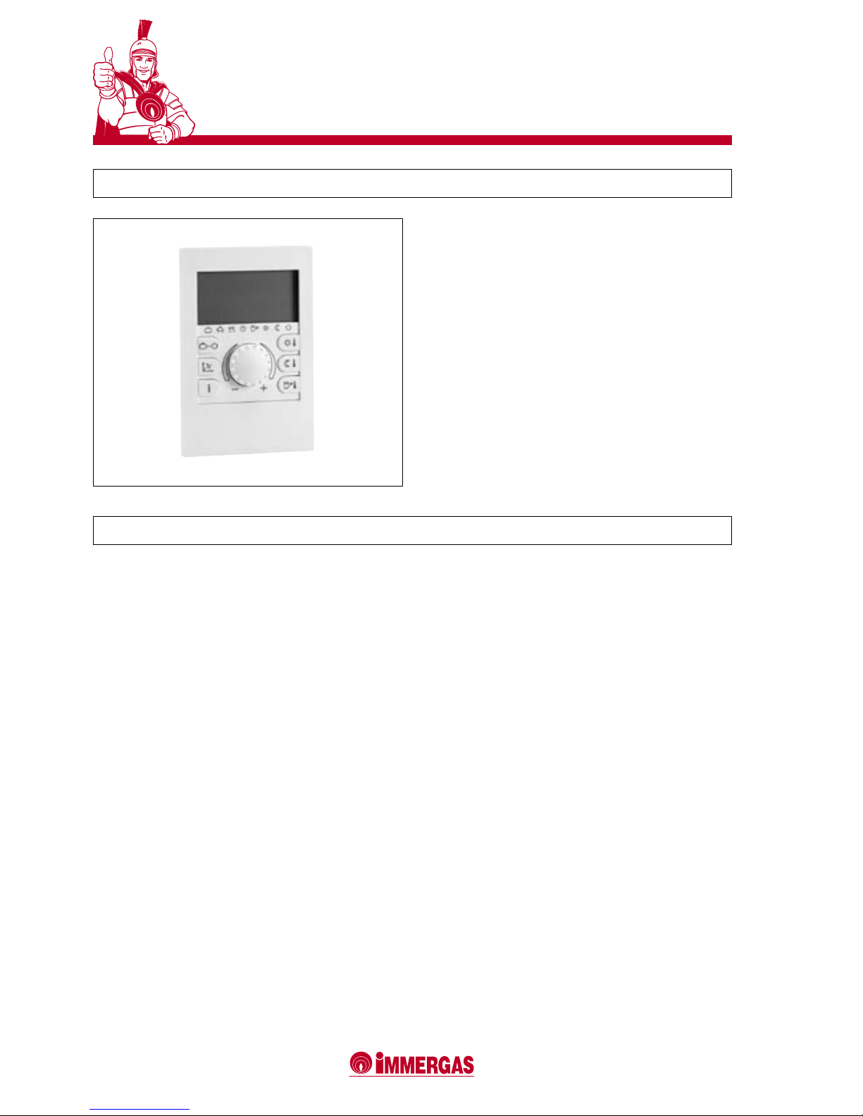
9 ZONE CONTROLLER (CE 3.015264)
The zone controller only operates in conjunction with the
series regulator. Besides the functions described for the series
thermoregulator, it allows the user to keep all the important
information concerning the operation of the appliance and
heating system under control and particularly ready to hand.
This means that the previously set parameters can be easily
modied without having go go to the place where the series
regulator is installed. the climatic timer-thermostat built
into the remote control panel allows the system's delivery
temperature to be adapted to the effective needs of the place
being heated so as to obtain the required ambient temperature
with the utmost precision and, thus, with evident savings in
running costs. The controller also allows the ambient temperature and effective outdoor temperature to be displayed (this
latter if the external probe is installed). The zone controller is
powered by the series thermoregulator by means of 2 BUS
data cables.
9.1 SPECIFICATIONS
2 BUS data cables up to 50 meters in length are used to
connect to the series and zone regulator, allowing the device
to:
• control up to one zone;
• enter two ambient temperature values, one for the daytime
(comfort temp.) and one for the night (lower temp.);
• control the temperature of the domestic hot water (in
conjunction with a water heater Unit);
• select the operating mode for the heating and hot water
production functions of each individual hydraulic circuit:
- comfort temperature mode,
- low temperature mode,
- adjustable antifreeze temperature mode;
• control the boiler delivery temperature according to the outdoor temperature (in conjunction with the external probe),
with climatic curve settings;
• obtain information about the system:
- temperature of the system,
- operating mode,
- meter data,
- timer program,
- pump operating status,
- variable input values and operation;
• enter the operating parameters:
- operating times,
- operating mode,
- domestic hot water,
- direct, mixed 1, mixed 2 circuits,
- date and time;
• display operating faults with their relative error codes by
means of the check-control system;
• display the date, time, day of the week and temperature of
the generator.
Page 9
9
VICTRIX 50
11 EXTERNAL PROBE (CODE 3.015266)
The external probe allows the maximum temperature delivered to the system to be automatically lowered or raised as
the outdoor temperature rises or lowers, thus adapting the
heat supplied to the system to suit the outdoor temperature
variations.
The probe is connected straight to the boiler's terminal board
with two wires. Once connected, it always acts even without
the thermoregulation kit.
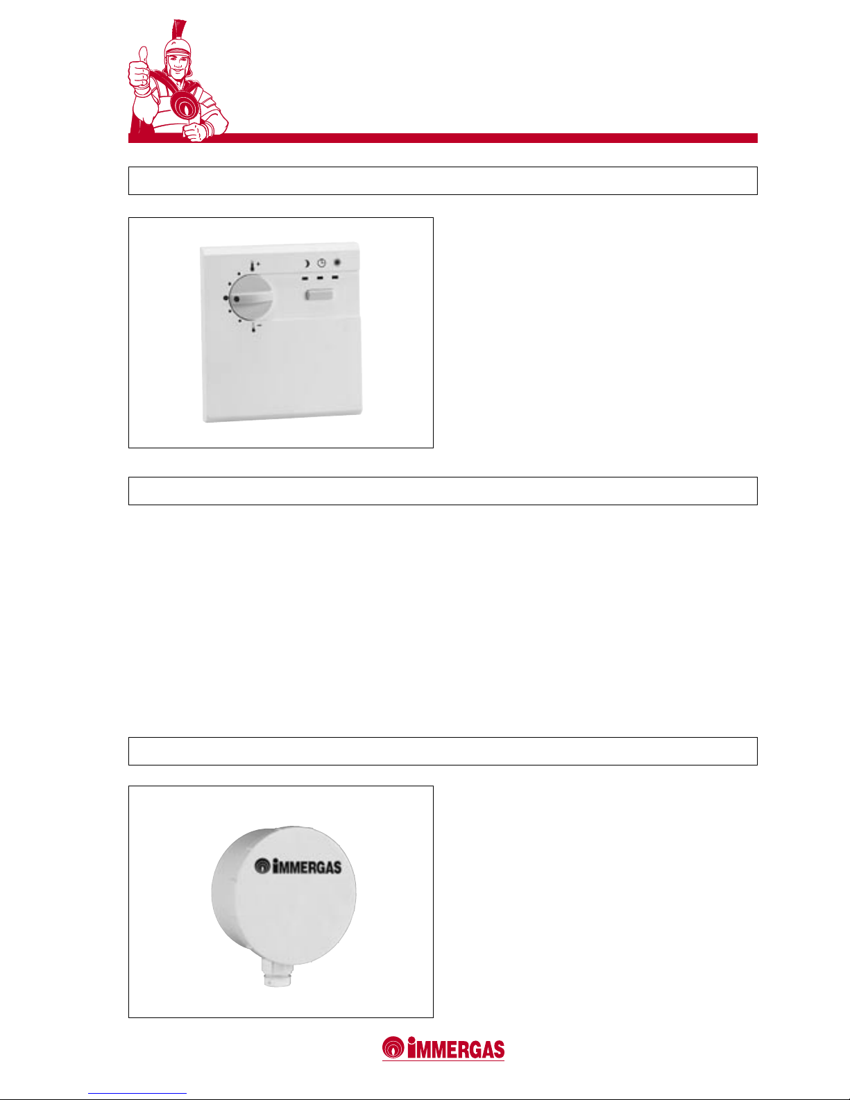
10 MODULATING AMBIENT THERMOSTAT (CODE 3.015245)
The modulating ambient thermostat (not a conventional
On/Off model) only operates in conjunction with the series
regulator and allows the user to regulate the ambient temperature of one of the zones into which the system is divided
(both in individual and series installations).
The regulation curve of the ambient temperature in the zone
can be modied by means of the series regulator itself.
The modulating ambient thermostat is powered by the series
thermoregulator via 2 BUS data cables.
10.1 SPECIFICATIONS
2 BUS data cables up to 50 meters in length are used to
connect to the series and zone regulator, allowing the device
to:
• control up to one zone;
• vary the ambient temperature of the zone;
• select the operating mode for the zone heating function:
- xed comfort temperature mode,
- xed low temperature mode,
- operation with the timer program.
Page 10
10
VICTRIX 50
11
VICTRIX 50
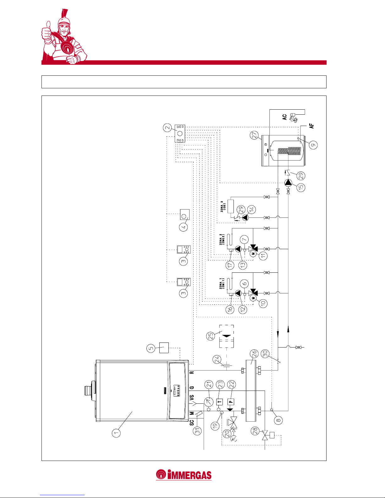
12 EXAMPLES OF VICTRIX 50 INSTALLATIONS WITH A SINGLE BOILER
LEGEND:
1 - VICTRIX 50 generator
2 - Series and zone regulator
3 - Zone controller
4 - Modulating ambient thermostat
5 - External probe
6 - Zone 1 temperature probe 1 (CMI-1)
7 - Zone 2 temperature probe 2 (CMI-2)
8 - Common delivery probe
9 - Temperature probe of Water heater unit
10 - Zone 1 mixer valve (CMI-1)
11 - Zone 2 mixer valve (CMI-1)
12 - Zone 1 heating circuit pump (CMI-1)
13 - Zone 2 heating circuit pump (CMI-2)
14 - Zone 3 direct circuit pump (CD)
15 - Water heater unit supply pump
16 - Zone 1 safety thermostat (CMI-1)
17 - Zone 2 safety thermostat (CMI-2)
19 - Fuel on-off valve bulb
20 - ISPESL approved pressure gauge cock
21 - ISPESL approved thermometer
22 - ISPESL approved manually reset pressure switch
23 - ISPESL approved manually reset thermostat
24 - Expansion tank connection
25 - Expansion tank
26 - Manifold/mixer
27 - External water heater unit
28 - Fuel on-off valve
29 - Check valve
30 - Sludge collecting system lter
31 - Thermometer trap
Page 11
11
VICTRIX 50
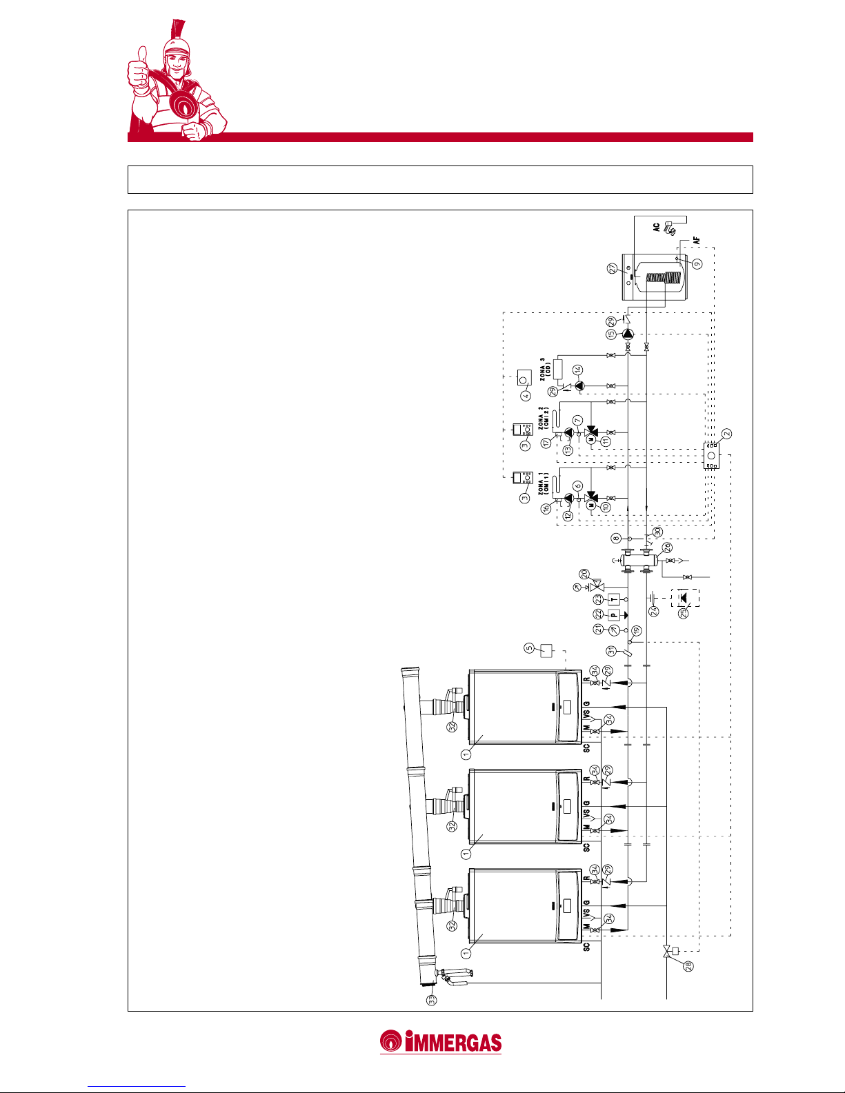
13 EXAMPLES OF VICTRIX 50 INSTALLATIONS IN SERIES
LEGEND:
1 - VICTRIX 50 generator
2 - Series and zone regulator
3 - Zone controller
4 - Modulating ambient thermometer
5 - External probe
6 - Zone 1 temperature probe (CMI-1)
7 - Zone 2 temperature probe (CMI-2)
8 - Common delivery probe
9 - Water heater unit temperature probe
10 - Zone 1 mixer valve (CMI-1)
11 - Zone 2 mixer valve (CMI-1)
12 - Zone 1 heating circuit pump (CMI-1)
13 - Zone 2 heating circuit pump (CMI-2)
14 - Zone 3 direct circuit pump (CD)
15 - Water heater unit supply pump
16 - Zone 1 safety thermostat (CMI-1)
17 - Zone 2 safety thermostat (CMI-2)
19 - Fuel on-off valve bulb
20 - ISPESL approved pressure gauge cock
21 - ISPESL approved thermometer
22 - ISPESL approved manually reset pressure switch
23 - ISPESL approved manually reset thermostat
24 - Expansion tank connection
25 - Expansion tank
26 - Manifold/mixer
27 - External water heater unit
28 - Fuel on-off valve
29 - Check valve
30 - Sludge collecting system lter
31 - Thermometer trap
32 - Draught circuit air lock
33 - Condensation drain pipe
34 - System on-off cock
Page 12
12
VICTRIX 50
13
VICTRIX 50
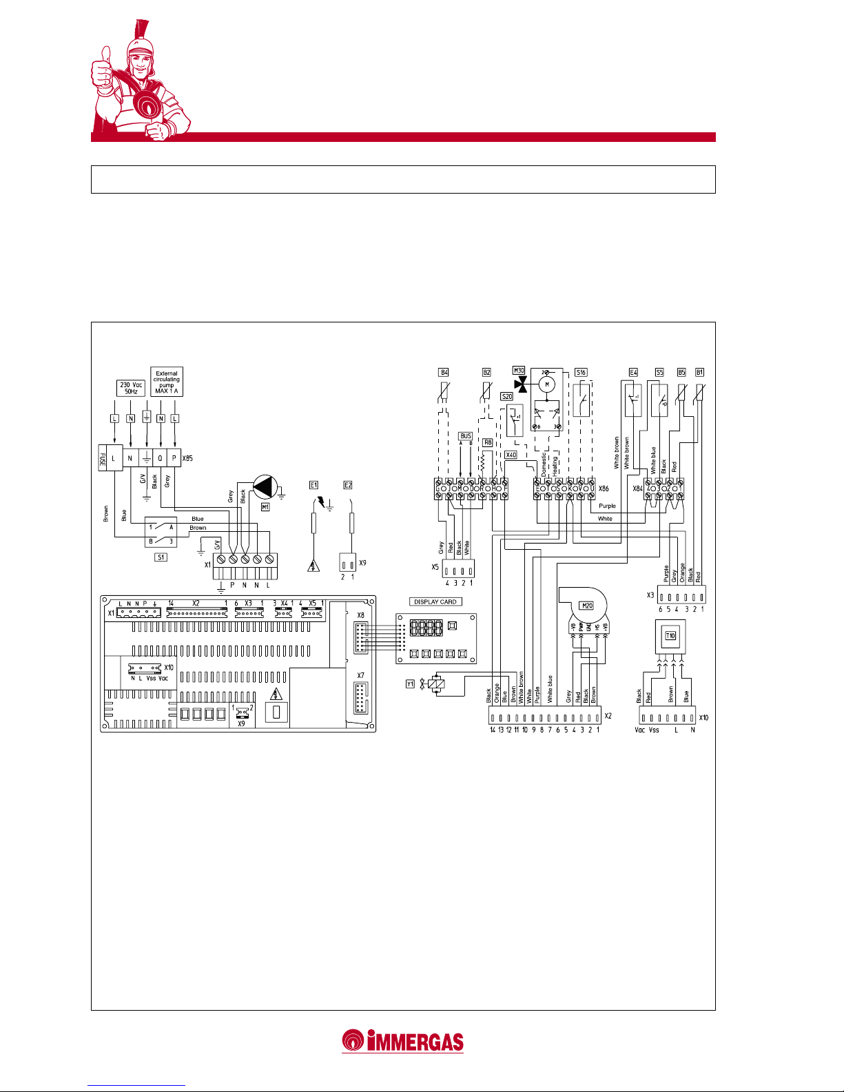
OPTIONAL ELECTRICAL CONNECTIONS.
The M and O terminals of thr Bus are connected in order to
use the series and zone regulator.
The ambient thermostat (S20) must be connected to terminals
F and E, eliminating jumper X40. The external probe (B4) must
be connected to terminals G and J.
LEGEND:
B1 - Delivery probe
B2 - Domestic water probe (optional)
B4 - External probe (optional)
B5 - Return probe
E1 - Ignition electrode
E2 - Detection electrode
E4 - Safety thermostat
M1 - Boiler circulator
M20 - Fan
M30 - Three-way valve (optional)
R8 - Water heater function inhibiting resistance
S1 - Main switch
S5 - System pressure switch micro
S16 - Summer switch (optional)
S20 - Ambient thermostat (optional)
T10 - Low voltage transformer
X40 - Ambient thermostat jumper
Y1 - Gas valve (24 Vdc)
14 WIRING DIAGRAM
The domestic water probe (B2) must be connected to terminals R and H, eliminating the resistance (R8).
The three-way valve (M30) should be connected to terminals
T, S and K.
The summer switch (S16) must be connected to terminals
V and U.
Page 13
13
VICTRIX 50
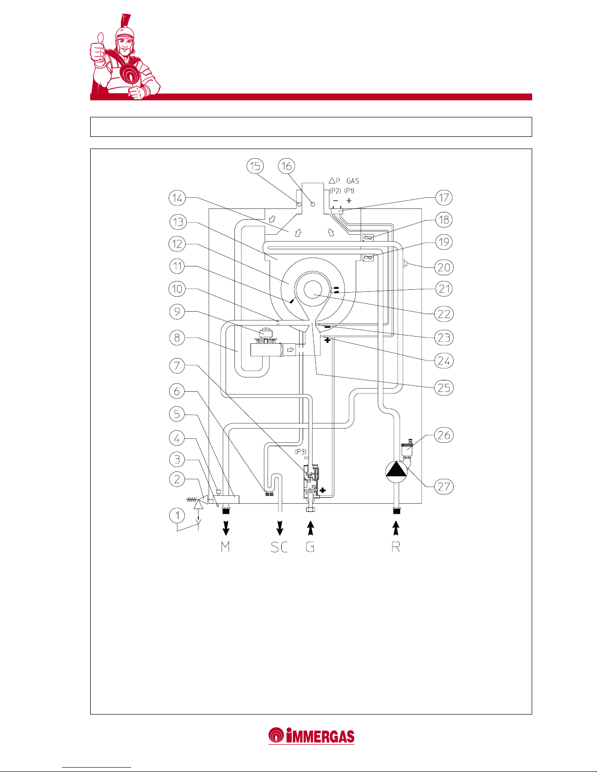
LEGEND:
1 - Visible funnel outlet
2 - ISPESL-approved 4 bar safety valve
3 - Boiler emptying cock
4 - Absolute pressure switch
5 - Delivery manifold
6 - Condensation trap
7 - Gas valve
8 - Air intake pipe
9 - Air ventilator
10 - Gas nozzle
11 - Detection electrode
12 - Condensing module cover
13 - Condensing module
14 - Draught diverter
15 - Air analyzer intake
16 - Fumes analyzer intake
17 - Δp gas pressure point
18 - System delivery regulating probe
19 - System return regulating probe
20 - Overtemperature safety thermostat
21 - Ignition electrode
22 - Burner
23 - Venturi negative signal (P2)
24 - Venturi positive signal (P1)
25 - Air/gas Venturi manifold
26 - Automatic air venting valve
27 - Boiler circulator
15 HYDRAULIC LAYOUT
Page 14

14
VICTRIX 50
15
VICTRIX 50
“GREEN SERIES” INTAKE/EXHAUST KIT FOR VICTRIX 50
16 TYPE OF INSTALLATION
VICTRIX 50 boilers are approved for installation both inside
and outside the heat plant.
The "VICTRIX 50" boiler leaves the factory in the "B23" conguration (open chamber and forced draught). To change the
boiler conguration to type "C" (sealed chamber and forced
draught), dismantle the Ø 80 adapter, the plate and the seal
on the boiler cover so that the relative Ø 80/125 kits can be
used.
To correctly install the boiler, use the special Immergas
"Green" series air intake/fumes exhaust kit since the materials,
components and accessories have been specically designed
for this type of appliance.
The kits are made of plastic material so as to provide high resistance to corrosion and make them very quick and functional
to install, also thanks to the push-in connection mechanism
and the silicone seals.
The boiler classication varies when the type of installation
changes:
Configuration type C with sealed chamber and forced
draught.
The boiler is installed using the relative Ø 80/125 concentric
kits after having disassembled the Ø 80 adapter, the plate and
the seal from the boiler cover.
Air is thus inlet and fumes exhausted directly outside the
building.
The following can be used as concentric intake/exhaust kit:
Concentric Ø 80/125 horizontal kit Code 3.015242;
Concentric Ø 80/125 vertical kit Code 3.015243.
Configuration type B23 with open chamber and forced
draught.
The boiler is installed using the Ø 80 adapter provided with the
boiler as part of the standard supply and to which the relative
Ø 80 fumes exhaust kit should be connected.
The air is taken straight from the room in which the boiler
is installed, while the fumes are exhausted through the ue
or straight outdoors. This means that the installation must
only be made in conjunction with one of the following fumes
exhaust kits:
Ø 80 horizontal terminal kit for wall-mounted exhausts
Code 3.015255;
Ø 80 horizontal kit for ue exhausts
Code 3.015254;
Ø 80 vertical terminal kit for direct exhausts
Code 3.015256.
When installed singly, again in the "B23" conguration, VICTRIX
50 can also be used in conjunction with the Ø 80 hose pipe
system for condensing boilers.
This method is particularly suitable for stacks or ues (or
technical apertures) that are not perfectly straight and where
a rigid piping system could be difcult to install.
When installed in series in heat plants or technical rooms,
special fumes manifolds can be used for exhausting into ues
equipped with non-return devices (air-locks) to prevent the
boiler's products of combustion from interfering with the
combustion circuits of other boilers that are off.
Page 15
15
VICTRIX 50
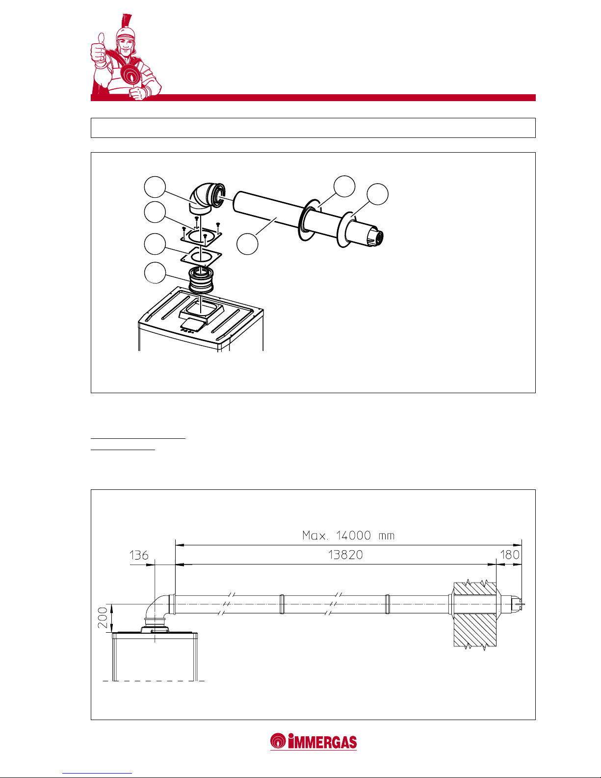
MAXIMUM TOLERATED LENGTH OF
Ø 80/125 HORIZONTAL KIT
Available resistance factor 100
Horizontal meters 14 + the rst
90° elbow
2
1
3
4
7
5
6
17 Ø 80/125 CONCENTRIC HORIZONTAL KIT (CODE 3.015242)
THE KIT INCLUDES:
1 - 1 (one) Ø 80/125 adapter
2 - 1 (one) seal
Part (3) is standard supply with the boiler
4 - 1 (one) Ø 80/125 concentric elbow a 87°
5 - 1 (one) Ø 80/125 concentric intake/exhaust terminal
6 - 1 (one) internal rose
7 - 1 (one) external rose
Page 16
16
VICTRIX 50
17
VICTRIX 50
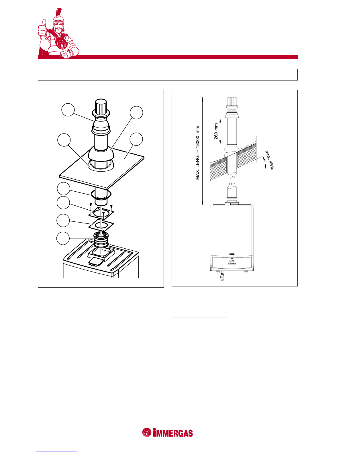
MAXIMUM TOLERATED LENGTH OF
Ø 80/125 VERTICAL KIT
Available resistance factor 100
Vertical meters 18
THE KIT INCLUDES:
1 - 1 (one) Ø 80/125 adapter
2 - 1 (one) seal
Part (3) is standard supply with the boiler
4 - 1 (one) rose
5 - 1 (one) aluminium plate
6 - 1 (one) xed half-shell
7 - 1 (one) Ø 80/125 concentric int./exh. terminal
8 - 1 (one) movable half-shell
2
1
3
4
5
8
7
6
18 Ø 80/125 CONCENTRIC VERTICAL KIT (CODE 3.015243)
Page 17
17
VICTRIX 50
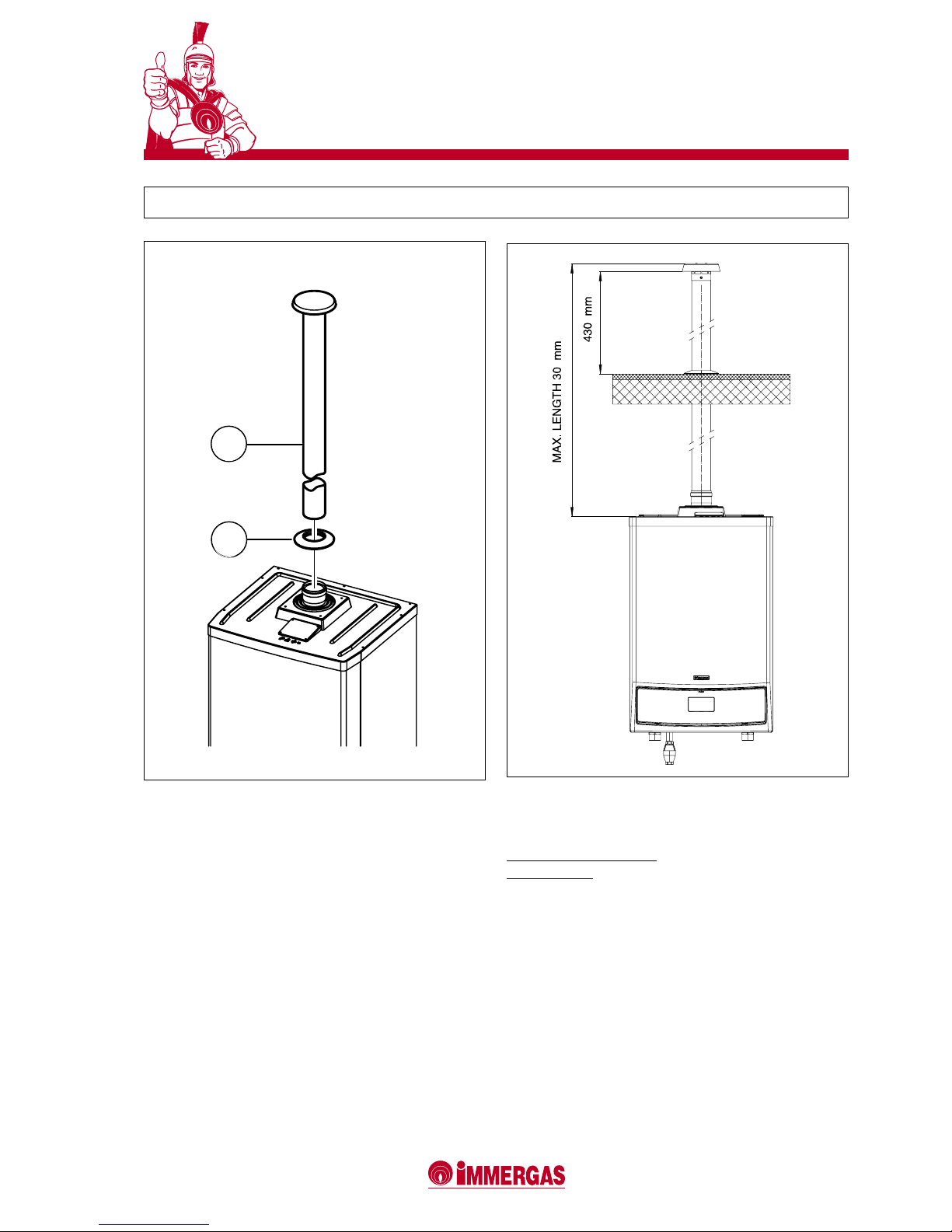
MAXIMUM TOLERATED LENGTH OF
Ø 80 VERTICAL KIT
Available resistance factor 100
Vertical meters 30
THE KIT INCLUDES:
1 - 1 (one) rose
2 - 1 (one) Ø 80 exhaust terminal
2
1
19 Ø 80 VERTICAL KIT (CODE 3.015256)
Page 18
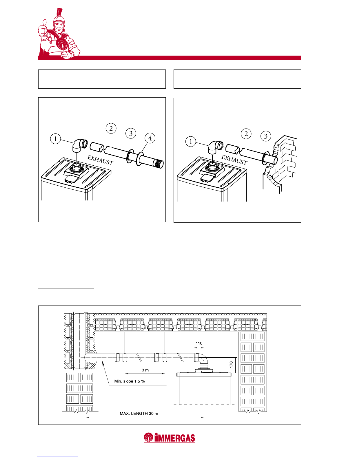
18
VICTRIX 50
19
VICTRIX 50
MAXIMUM TOLERATED LENGTH OF
Ø 80 HORIZONTAL KIT
Available resistance factor 100
Horizontal meters 30
20 Ø 80 HORIZONTAL TERMINAL KIT FOR
WALL-MOUNTED EXHAUST (CODE 3.015255)
20.1 Ø 80 HORIZONTAL TERMINAL KIT FOR
STACK EXHAUSTS (CODE 3.015254)
THE KIT INCLUDES:
1 - 1 (one) 90° Ø 80 elbow
2 - 1 (one) Ø 80 exhaust pipe
3 - 1 (one) internal rose
THE KIT INCLUDES:
1 - 1 (one) 90° Ø 80 elbow
2 - 1 (one) Ø 80 exhaust pipe
3 - 1 (one) internal rose
4 - 1 (one) external rose
Page 19

19
VICTRIX 50
Each component of the air intake/combustion product
exhausting system possesses a resistance factor calculated by means of tests and given in the following tables.
The resistance factor of each individual component is a
dimensionless magnitude. This parameter is conditioned by
the temperature of the uid and, thus, varies depending on
whether the component in question is installed in the air
intake section or in the part where the combustion products
are exhausted.
Each component also has a resistance corresponding to a
certain length in meters of pipe of the same diameter: this
is the so-called “equivalent length” obtained from the ratio
between the relative resistance factors.
To identify the link between these two parameters in the best
possible way, rst consider an 80 mm diameter 90° elbow
as an example. It possesses a 2.6 resistance factor on the
exhausting part. However, if a pipe 80 mm in diameter and 1
meter in length is taken as a reference, it will be found to have
a 1.2 resistance factor on the exhausting part. The equivalent
length “Leq” of the considered elbow will therefore be:
Leq = 2,6 : 1.2 = 2.1 m of Ø 80 mm pipe (on the exhaust).
Very briey, the loss of head of an 80 mm diameter 90° elbow
is the same as that of a 2.1 m length straight pipe of the same
diameter (installed on the fumes outlet).
All boilers have a maximum resistance factor of 100, calculated experimentally. The maximum tolerated resistance
factor corresponds to the resistance found with the maximum
tolerated pipe length.
All this information allows calculations to be made in order to
ascertain whether the various congurations of the system are
feasible. In short, to ensure that the appliance operates in the
correct way, every air intake/combustion product exhaust
conguration must have a maximum overall resistance
factor of 100. This limit must not therefore be exceeded
when the resistance factors of the individual components
used are added together.
The resistance factors and equivalent losses in meters are
given in the catalogue in relation to:
- the “Green series” fumes exhaust pipes to use when making
the combustion-aiding air supply pipes and fumes exhaust
pipes (i.e. the pipes that connect the appliance and the
stack/ue/ducted pipe);
- the components to use for making the Ø 80 mm hose
pipe ducting system for condensing boilers, described
further on in this brochure (meaning the mainly vertical
pipe specically installed to collect the eliminate the products of combustion as well as being able to withstand
their components and condensation and t for installation
in an already existing and not perfectly straight stack/ue/
technical aperture).
21 RESISTANCE FACTORS AND EQUIVALENT LENGTHS
Page 20
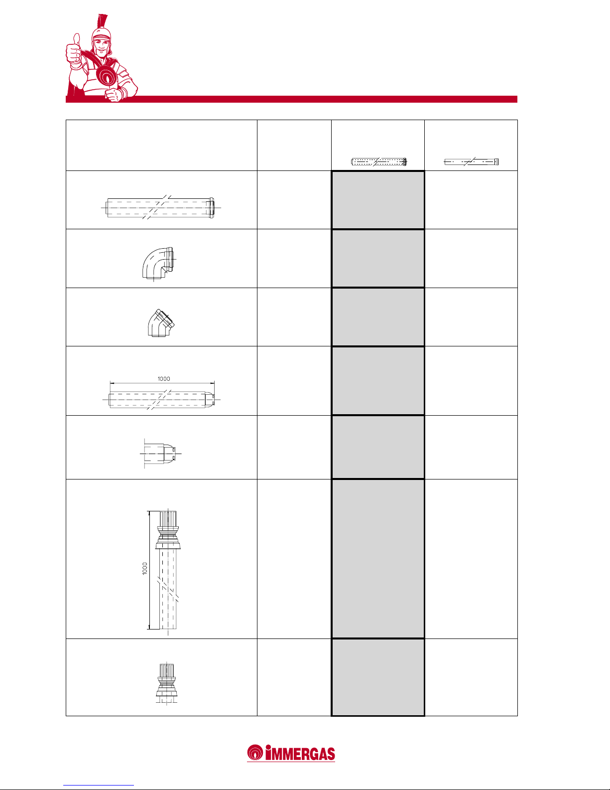
20
VICTRIX 50
21
VICTRIX 50
TYPE OF DUCT
Resistance
Factor
(R)
Equivalent
length in m of Ø 80/125
concentric pipe
Equivalent
length
in m of Ø 80 pipe
Ø 80/125 m 1 concentric pipe
4.9
Intake
and
exhaust
1.0 m
4.0 m
exhaust
90° elbow Ø 80/125 concentric pipe
9.5
Intake
and
exhaust
1.9 m
7.9 m
exhaust
45° elbow Ø 80/125 concentric pipe
6.8
Intake
and
exhaust
1.4 m
5.6 m
exhaust
Terminal complete with Ø 80/125 horizontal concentric
intake-exhaust pipe
26.8
Intake
and
exhaust
5.5 m
22.3 m
exhaust
Ø 80/125 horizontal concentric intake-exhaust terminal
22.9
Intake
and
exhaust
4.7 m
19.0 m
exhaust
Terminal complete with Ø 80/125 vertical concentric
intake-exhaust pipe
16.7
Intake
and
exhaust
3.4 m
13.9 m
exhaust
Ø 80/125 vertical concentric intake-exhaust terminal
13.3
Intake
and
exhaust
2.7 m
11.0 m
exhaust
Page 21
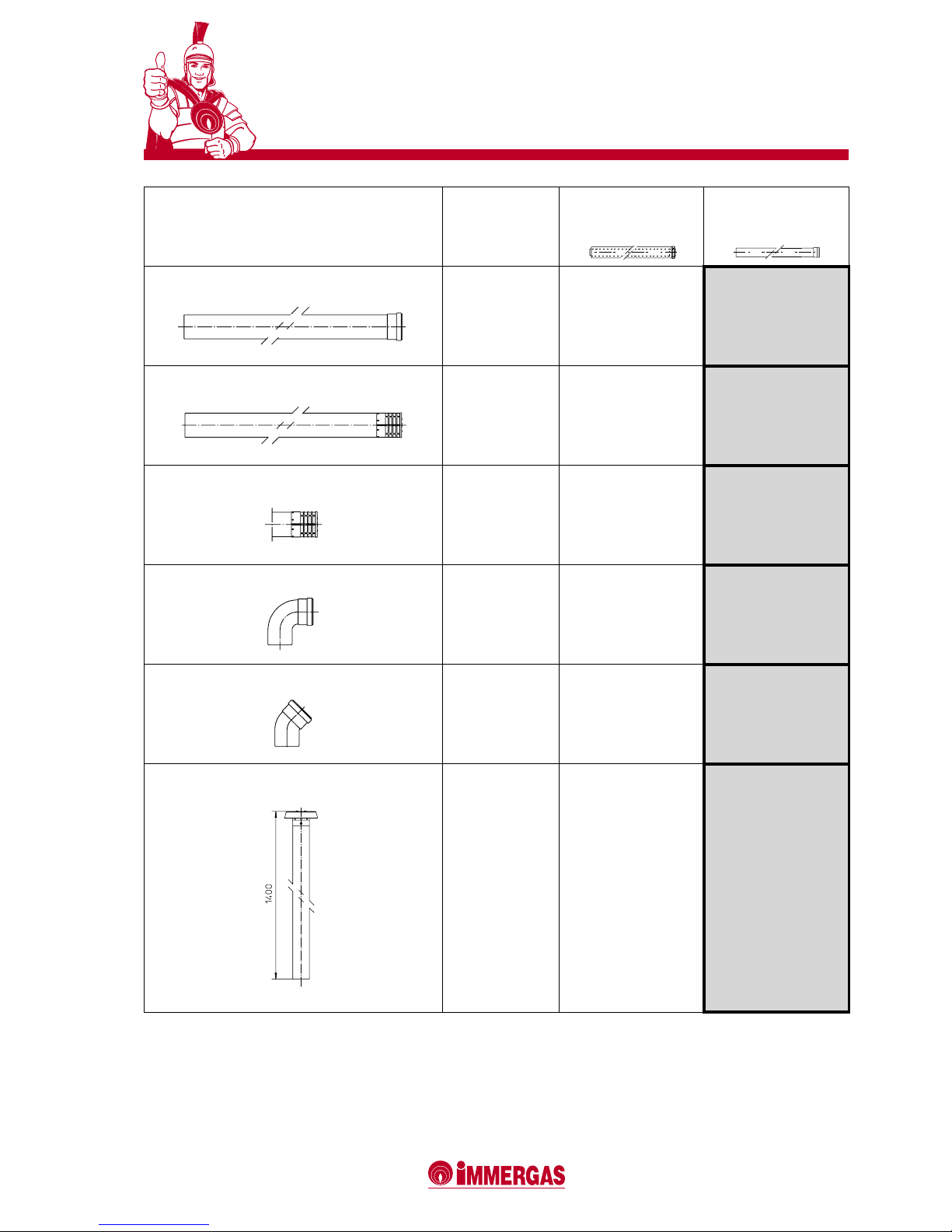
21
VICTRIX 50
TYPE OF DUCT
Resistance
factor
(R)
Equivalent
length in m of Ø 80/125
concentric pipe
Equivalent
length in m of
Ø 80 pipe
Ø 80 m 1 pipe
1.2
exhaust
0.24 m
1.0 m
exhaust
Terminal complete with Ø 80 m 1 exhaust pipe
3.1
exhaust
0.63 m
2.6 m
exhaust
Ø 80 exhaust terminal
1.9
exhaust
0.38 m
1.6 m
exhaust
90° Ø 80 elbow
2.6
exhaust
0.53 m
2.1 m
exhaust
45° Ø 80 elbow
1.6
exhaust
0.32 m
1.3 m
exhaust
Terminal complete with Ø 80 vertical exhaust pipe
3.6
exhaust
0.73 m
3 m
exhaust
Page 22
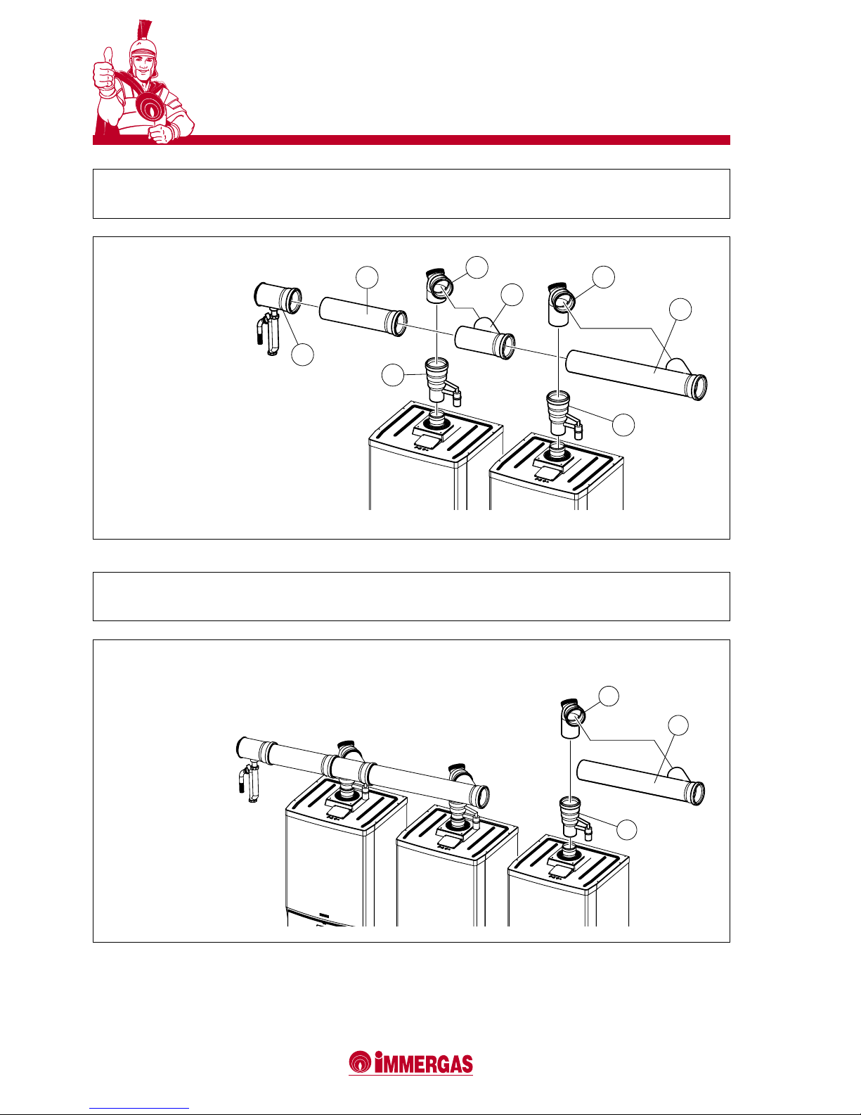
22
VICTRIX 50
23
VICTRIX 50
4
7
5
8
2
1
10
11
9
3
6
22.1 FUMES EXHAUST MANIFOLD KIT
WITH ADDITIONAL BOILER IN SERIES (CODE 3.015241)
THE KIT INCLUDES:
1 - 1 (one) stub pipe with air lock
2 - 1 (one) stub pipe with air lock
4 - 1 (one) elbow (can be inspected)
5 - 1 (one) elbow (can be inspected)
7 - 1 (one) short pipe
8 - 1 (one) long pipe
10 - 1 (one) pipe
11 - 1 (one condensation drain pipe
To complete the installation and connect the fumes manifold
to a stack, use a kit comprising a 2 m length Ø 125 mm
extension pipe Code 3.015250.
THE KIT INCLUDES:
3 - 1 (one) stub pipe with air lock
6 - 1 (one) elbow (can be inspected)
9 - 1 (one) long pipe
22 FUMES EXHAUSTING MANIFOLD KIT
WITH TWO BOILERS IN SERIES (CODE 3.015240)
Page 23
23
VICTRIX 50
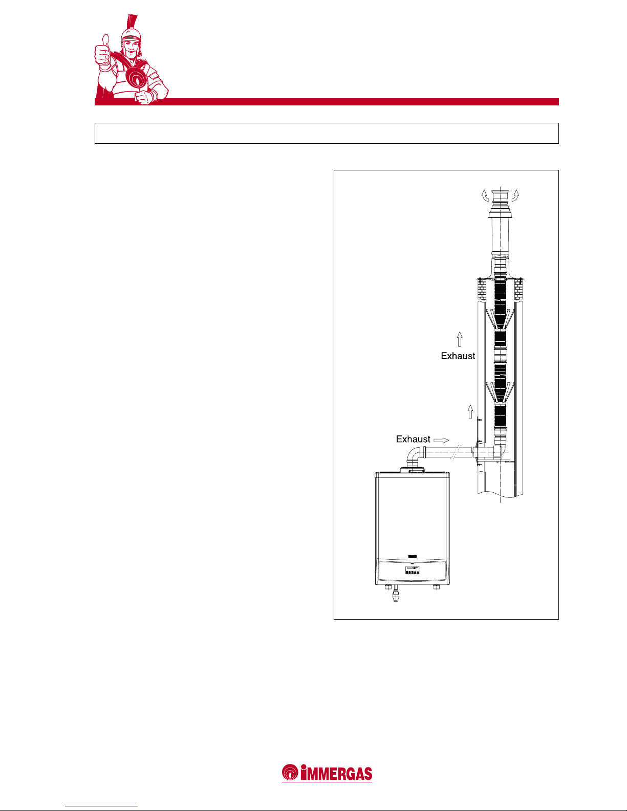
23 Ø 80 HOSE PIPE DUCTING SYSTEM
The Immergas Ø 80 mm hose pipe ducting system for already
existing stacks comprises a series of components, considered
as single kits, which can be assembled to suit the specic
installation requirements. This system is supplied in a conguration that includes an 87° rising inlet elbow which then
proceeds vertically with the Ø 80 hose pipe and the outlet
terminal. The ducted pipe can be inspected through a ap in
the part where it connects to the boiler.
The kit consists of a 12 m length hose pipe. If the pipe
is too short, it can be joined to other pieces by means of
adapters.
A centering spacer with expanding ns must be added every
so often in order to ensure that the pipe keeps to the middle
of the stack.
The maximum length that can be covered with this type of
piping system is 30 m (approx.).
This length is obtained considering:
- 1 (one) Ø 80 mm 90° elbow for connection to the boiler
(on the outlet);
- 1 m of Ø 80 mm discharge pipe;
- two direction offshoots in the vertical section;
- the Ø 80 mm bearing elbow;
- the vertical terminal kit for Ø 80/125 pipes.
It is important to note that:
- only one appliance can be used with this system;
- the system can only be used with condensing applian-
ces.
Page 24
24
VICTRIX 50
25
VICTRIX 50
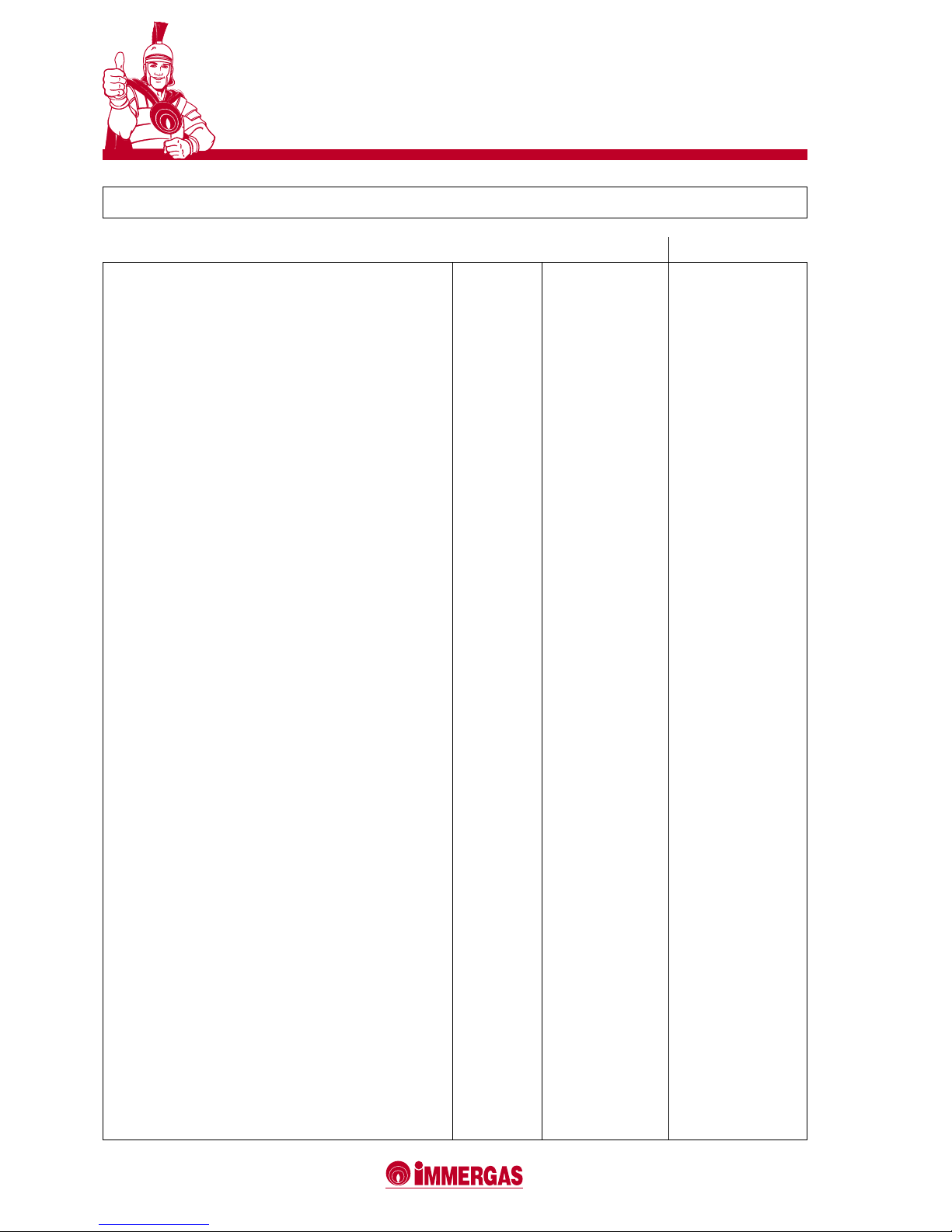
24 TECHNICAL SPECIFICATIONS
VICTRIX 50
Maximum nominal heat input kW (kcal/h) 50.8 (43,655)
Maximum nominal heat output kW (kcal/h) 50.0 (43,000)
Minimum nominal heat input kW (kcal/h) 10.4 (8,958)
Minimum nominal heat output kW (kcal/h) 10.0 (8,600)
100% Pn efciency (80/60°C) % 98.5
Efciency at 30% of load (80/60°C) % 99.0
100% Pn efciency (50/30°C) % 106.0
Efciency at 30% of load (50/30°C) % 107.2
100% Pn efciency (40/30°C) % 107.0
Efciency at 30% of load (40/30°C) % 107.2
Heating circuit
Central heating temperature adjustment °C 20-85
Maximum heating temperature of system °C 90
Maximum operating pressure of system bar 4.4
Available head with 1000 l/h ow rate kPa (m w.c.) 52.9 (5.4)
Gas supply
NATURAL GAS (G20) MIN - MAX mbar 0.37 - 6.40
nozzles N°- ø mm 1 x 7.85
LPG (G30) MIN - MAX mbar 0.31 - 5.71
nozzles N°- ø mm 1 x 5.70
LPG (G31) MIN - MAX mbar 0.38 - 6.81
nozzles N°- ø mm 1 x 5.70
Electric power supply V/Hz 230 - 50
Nominal power draw A 0.85
Electric power installed W 180
Fan power draw W 59
Circulator power draw W 115
Electrical insulation degree IP X5D
Storage tank capacity liters 3.7
Weight of empty boiler kg 63
Energy efciency marking (Directive 92/42/EEC) stars ««««
Page 25
25
VICTRIX 50
The gas ow rates refer to the NHV at 15°C and with 1013 mbar pressure.
The fumes temperature values refer to a 15°C inlet air temperature and 50°C delivery temperature.
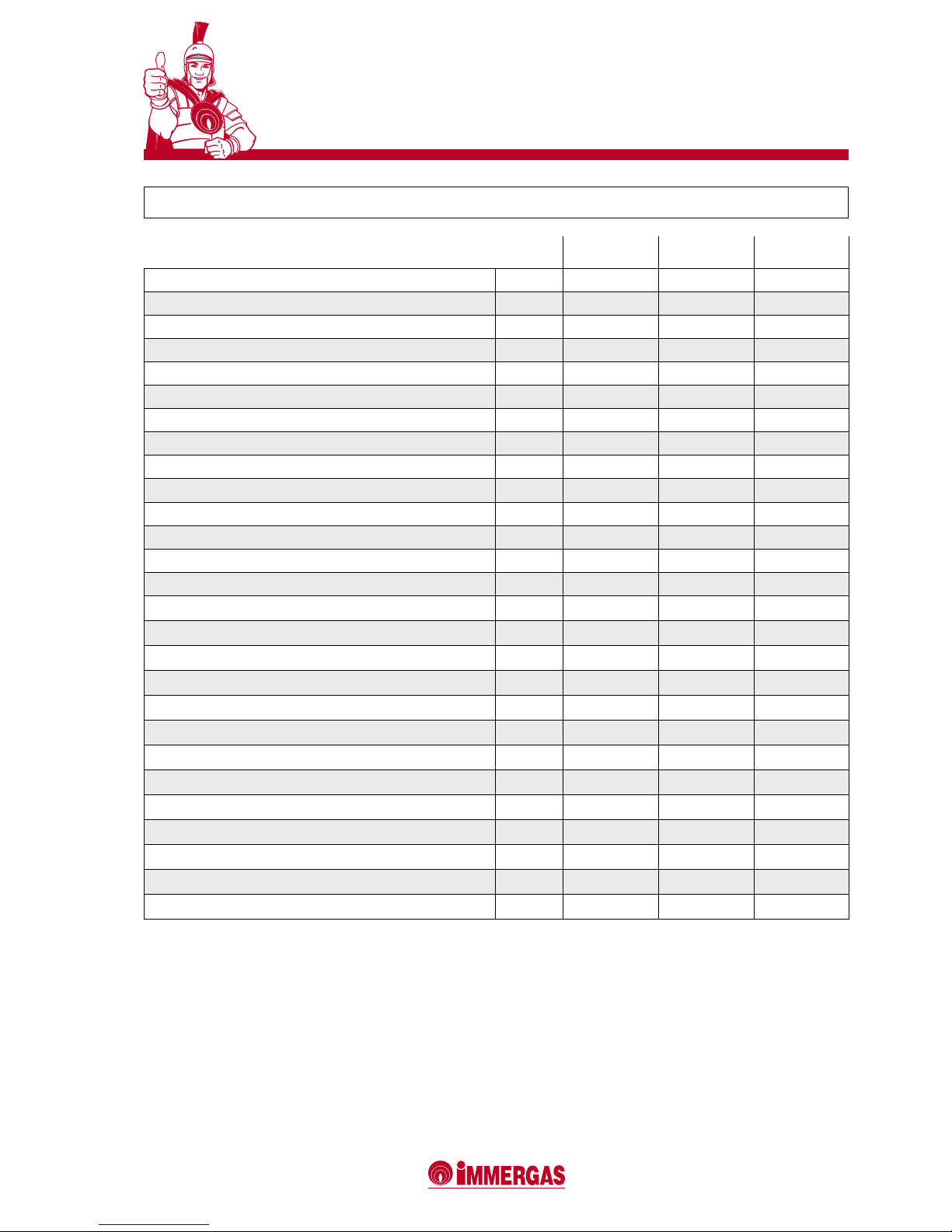
25 COMBUSTION SPECIFICATIONS OF VICTRIX 50
Nat.gas (G20) LPG (G30) GPL (G31)
100% Pn combustion efciency (80/60°C) % 98.75 98.75 98.75
P min combustion efciency (80/60°C) % 97.5 97.5 97.5
100% Pn useful efciency (80/60°C) % 98.5 98.5 98.5
P min useful efciency (80/60°C) % 96.0 96.0 96.0
100% Pn useful efciency (50/30°C) % 106.0 106.0 106.0
P min useful efciency (50/30°C) % 106.5 106.5 106.5
100% Pn useful efciency (40/30°C) % 107.0 107.0 107.0
P min useful efciency (40/30°C) % 107.0 107.0 107.0
Stack losses with burner on (100% Pn) (80/60°C) % 1.25 1.25 1.25
Stack losses with burner on (P min) (80/60°C) % 2.50 2.50 2.50
Stack losses with burner off % 0.02 0.02 0.02
Outer casing losses with burner off % 0.47 0.47 0.47
Outer casing losses with burner on (100% Pn) (80/60°C) % 0.25 0.25 0.25
Outer casing losses with burner on (P min) (80/60°C) % 1.50 1.50 1.50
Fumes temperature at Max. nominal heat input °C 38 40 39
Fumes temperature at Min. nominal heat input °C 30 32 33
Fumes ow rate at Max. nominal heat input kg/h 81 72 82
Fumes ow rate at Min. nominal heat input kg/h 17 15 17
CO2 at maximum heat input % 9.26 12.3 10.5
CO2 at minimum heat input % 9.0 11.7 10.1
CO at maximum heat input mg/kWh 128 709 159
CO at minimum heat input mg/kWh 6 10 7
NOx at maximum heat input mg/kWh 69 392 132
NOx at minimum heat input mg/kWh 28 97 48
Weighted CO mg/kWh 38 - -
Weighted NOx mg/kWh 55 - -
NOx class - 5 5 5
Page 26
26
VICTRIX 50
27
VICTRIX 50
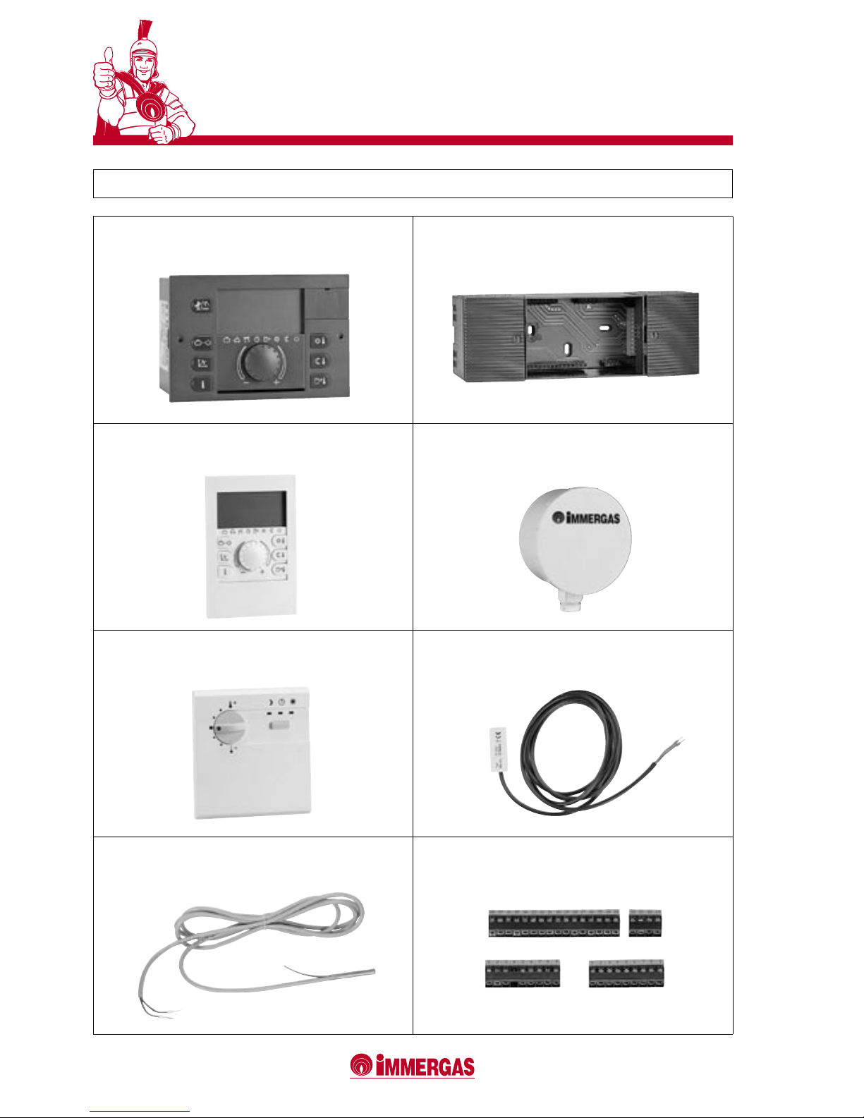
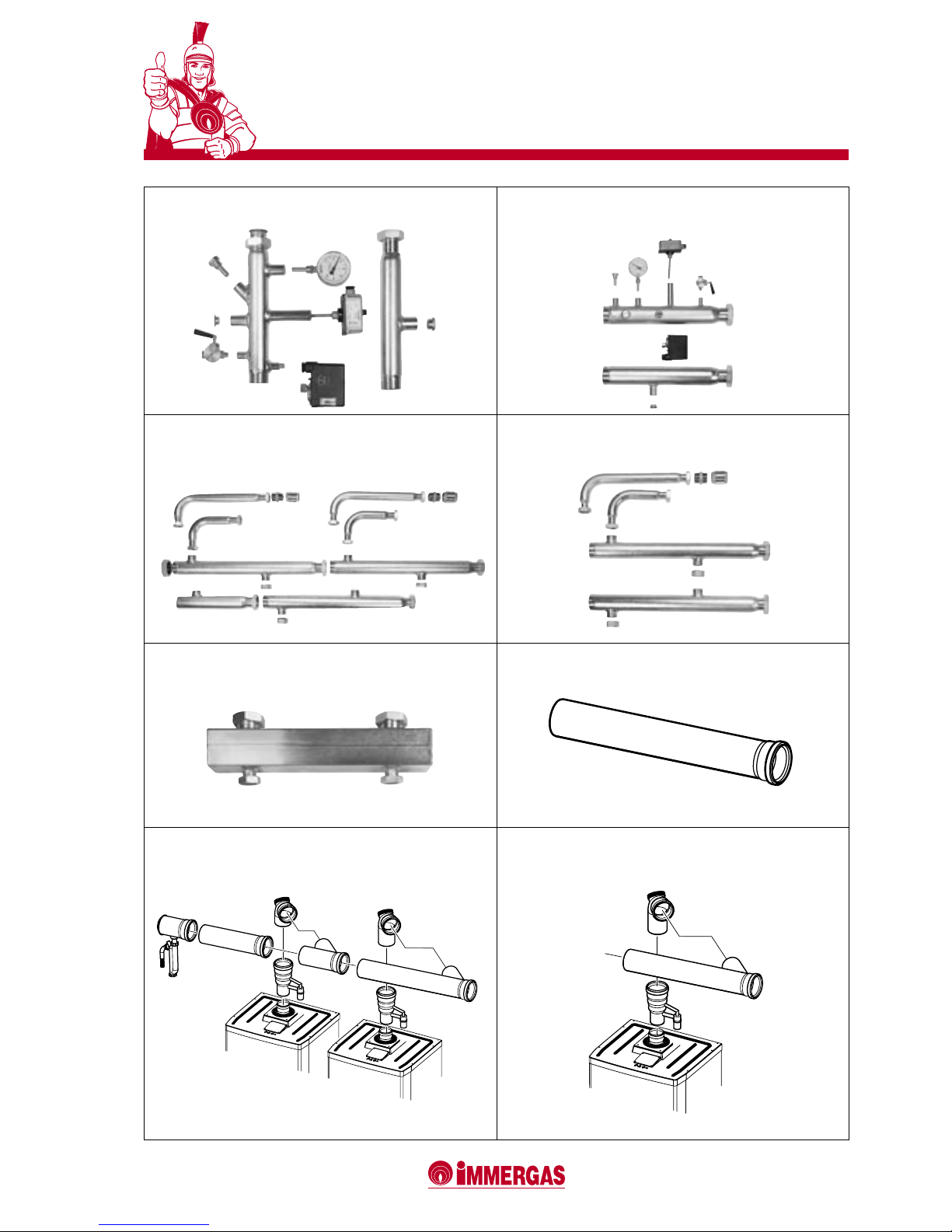
26 OPTIONALS
Series and zone thermoregulator kit
code 3.015244
Support kit for xing thermoregulator to the wall
code 3.015265
Zone controller kit
code 3.015264
External probe kit
code 3.015266
Modulating ambient thermostat kit
code 3.015245
System delivery probe kit
code 3.015267
Domestic water probe kit for external water heater
code 3.015268
Thermoregulator connector kit
code 3.015269
Page 27
27
VICTRIX 50
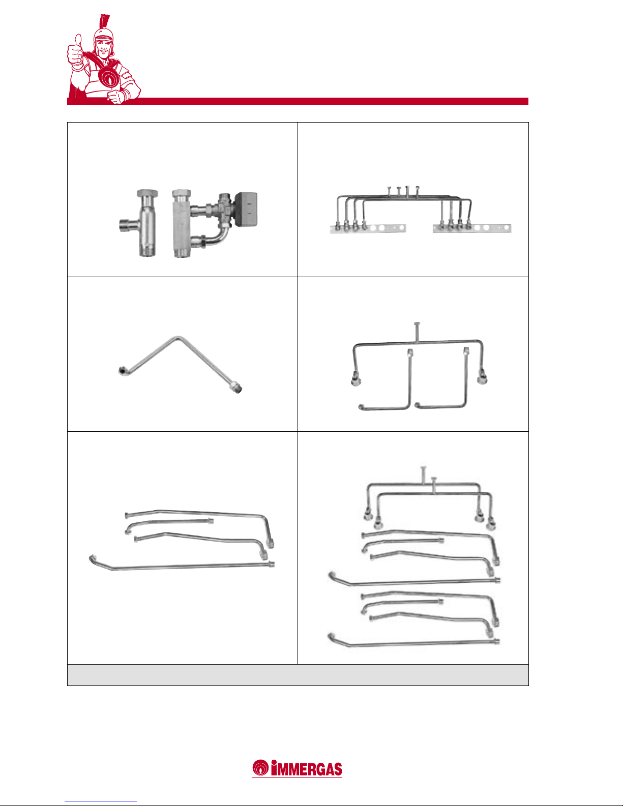
ISPESL safety pipe kit for single boiler
code 3.015222
ISPESL safety pipe kit for boilers in series
code 3.015227
Hydraulic manifold kit for connection
of two boilers in series
code 3.015225
Hydraulic manifold kit for additional boiler in series
code 3.015226
Hydraulic disconnector kit for single boiler
code 3.015224
125 fumes exhaust manifold extension kit
code 3.015250
Fumes exhaust manifold kit with air lock and
two boilers in series
code 3.015240
Fumes exhaust manifold kit with air lock and additional
boiler in series
code 3.015241
Page 28
28
VICTRIX 50
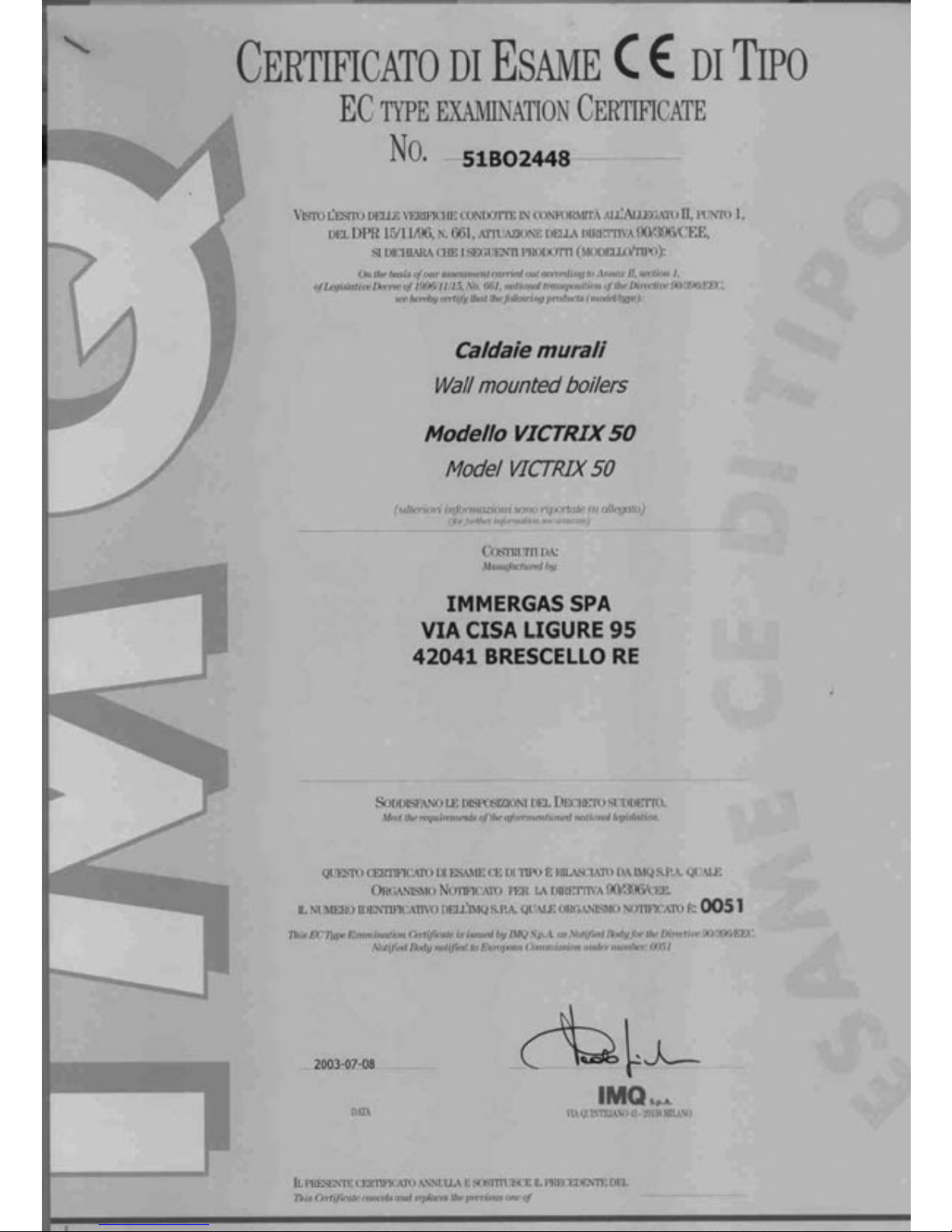
Three-way valve kit for use with external
water heater unit
(including water heater probe)
code 3.015223
UB 200 double water heater connection kit
code 3.015273
UB 200 re-circulation kit
code 3.015274
UB 200 connection kit for re-circulation in parallel
code 3.015342
UB 200 solar panel connection kit
code 3.015150
UB 200 kit for solar panel connection in parallel
code 3.015341
Antifreeze (-15°C) electric heating element kit code 3.015361
Page 29

Page 30

Page 31
Page 32
42041 Brescello (RE) Italy - Tel. 0522.689011 - Fax 0522.689102
www.immergas.com
During their working life,
the performances of the
products are influenced
by external factors such
as the hardness of the
domestic water, the weather conditions, scaling in
the system, etc. The data
indicated in this brochure
re fe r t o new products ,
in stal led and use d in
compliance with the current standards in force.
NOTE: re mem b er t o
ha ve y our ap pli anc e
pe rio dic a lly se rvi ced.
Immergas reserves the right to make all modications to the models considered necessary for product development without prior notice.
 Loading...