

Page 1
GB
Instruction booklet
and warning
Installer
User
Technician
VICTRIX 20-27
Page 2
Dear Customer,
Congratulations for choosing a high quality Immergas product designed to ensure lasting comfort and safety. As an
Immergas customer you can always count on a qualied Authorized Assistance Service able to guarantee the constant
eciency of your boiler.
Read the following pages carefully as they contain important information on correct use of the boiler, enabling you to
make the most of the Immergas product.
Contact our local Authorized Assistance Centre as soon as possible to request the preliminary operation test. Our
technician will verify correct operating conditions, make the necessary adjustments and will show you how to use the
appliance correctly.
In the event of problems or ordinary maintenance requirements, contact Immergas Authorized Centres, which have the
availability of original parts as well as personnel specically trained by the manufacturer.
General instructions
e instruction booklet is an integral part of the product and must be consigned to the user with the appliance.
It must be kept in a safe place and read carefully as it contains important information to ensure safe installation use
and maintenance.
Installation and maintenance must be performed in compliance with current regulations, the manufacturer’s instructions
and by professionally qualied personnel having specic technical expertise in the sector of these systems.
Incorrect installation can cause damage to persons, animals or things, for which the manufacturer is not responsible.
Maintenance must be performed by qualied technical personnel; in this case, the Immergas Authorized Technical
Assistance Service represents a guarantee of qualication and professionalism.
e appliance must be used for the purpose for which it is expressly designed. Any other use is considered improper and
therefore hazardous.
In case of errors in installation, operation or maintenance, due to non-compliance with current technical regulations,
standards or the instructions contained in this booklet (or in any case supplied by the manufacturer) the manufacturer
is relieved of any contractual or non-contractual responsibility for possible damage and the relevant appliance warranty
is invalidated.
Page 3

INDEX
Immergas S.p.A. declines any responsibility for printing or transcription errors, and reserves the right to make any changes to
its technical and commercial lists without prior notice.
INSTALLER page
USER page
TECHNICIAN page
1 Boiler installation ...................................................................................................................................................... 3
1.1 Installation instructions.............................................................................................................................................3
1.2 Main dimensions. ..................................................................................................................................................... 3
1.3 Connections..............................................................................................................................................................4
1.4 Boiler installation - B23 type with open chamber and forced draught (optional)....................................................... 6
1.5 Air intake and fume exhaust terminal installation...................................................................................................... 7
1.6 Ducting existing ues.............................................................................................................................................. 12
1.7 Fume exhaust to ue/chimney................................................................................................................................. 13
1.8 Chimneys/ues. ......................................................................................................................................................13
1.9 Filling of system. ..................................................................................................................................................... 14
1.10 Condensate trap lling. ........................................................................................................................................... 14
1.11 Gas system start-up. ................................................................................................................................................14
1.12 Boiler start-up (lighting). ........................................................................................................................................ 14
1.13 Circulating pump.................................................................................................................................................... 14
1.14 Kits available by request. .........................................................................................................................................15
1.15 Boiler components - Victrix 20. ..............................................................................................................................16
1.16 Boiler components - Victrix 27. ..............................................................................................................................17
2 Use and maintenance instructions........................................................................................................................... 18
2.1 Cleaning and maintenance. ..................................................................................................................................... 18
2.2 General instructions. ...............................................................................................................................................18
2.3 Control panel.......................................................................................................................................................... 19
2.4 Restoring heating system pressure. ..........................................................................................................................20
2.5 Draining the system. ...............................................................................................................................................20
2.6 Anti-freeze protection. ............................................................................................................................................ 20
2.7 Casing cleaning. ......................................................................................................................................................20
2.8 Decommissioning. ..................................................................................................................................................20
3 Boiler start-up (preliminary check).......................................................................................................................... 21
3.1 Wiring diagram - Victrix 20.................................................................................................................................... 21
3.2 Wiring diagram - Victrix 27.................................................................................................................................... 22
3.3 Plumbing diagram - Victrix 20................................................................................................................................ 23
3.4 Plumbing diagram - Victrix 27................................................................................................................................ 24
3.5 Troubleshooting...................................................................................................................................................... 25
3.6 Converting the boiler to another type of gas............................................................................................................ 25
3.7 Checks following conversion to another type of gas. ............................................................................................... 25
3.8 Possible adjustments................................................................................................................................................ 25
3.9 Air/gas ratio adjustment Victrix 20 boiler................................................................................................................ 26
3.10 Air-gas ratio adjustment Victrix 27 boiler................................................................................................................ 26
3.11 Combustion parameters check. ...............................................................................................................................26
3.12 Adjustment of boiler rated heating power................................................................................................................ 26
3.13 Circulating pump operation.................................................................................................................................... 26
3.14 “Chimney Sweep” function..................................................................................................................................... 26
3.15 Pump antiblocking function. .................................................................................................................................. 26
3.16 Radiator antifreeze function. ................................................................................................................................... 27
3.17 System delivery temperature too high...................................................................................................................... 27
3.18 Casing removal. ...................................................................................................................................................... 30
3.19 Yearly appliance maintenance and check. ................................................................................................................ 31
3.20 Variable heat output - Victrix 20............................................................................................................................. 32
3.21 Variable heat output - Victrix 27............................................................................................................................. 32
3.22 Technical data - Victrix 20. ..................................................................................................................................... 33
3.23 Technical data - Victrix 27. ..................................................................................................................................... 34
Page 4
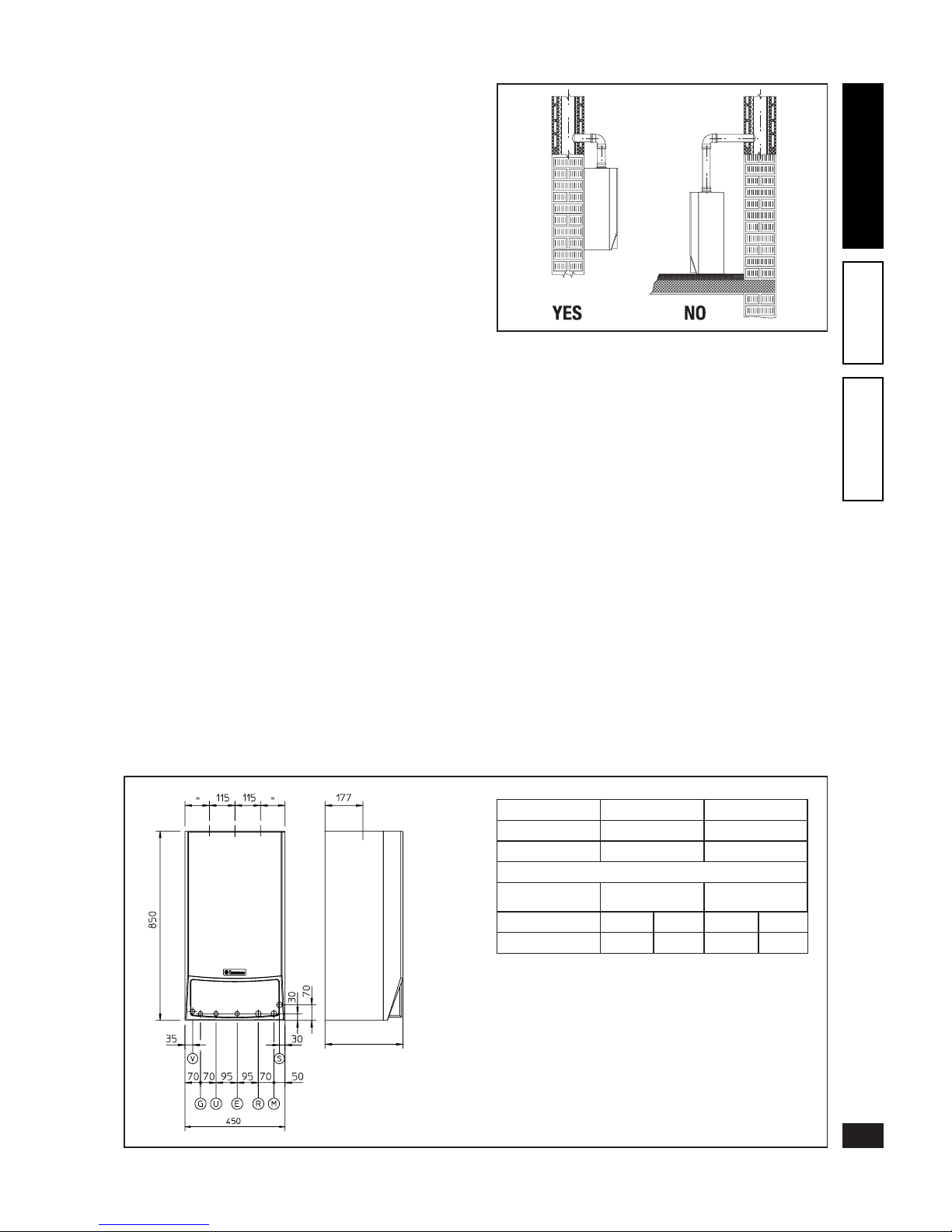
Key:
V - Electrical connection
G - Gas
U - Domestic hot water outlet
E - Domestic water inlet
R - System return
M - System delivery
S - Condensate drain (min. internal diameter Ø 13mm)
Important: wall mounting of the boiler must guarantee stable
and ecient support for the generator. e plugs supplied
standard with the appliance ensure adequate support only if
inserted correctly (according to technical standards) in walls
made of solid or cavity bricks. For walls made from bricks or
cavity blocks, partitions with limited static properties, or in
any case walls other than those indicated, a static test must
be carried out to ensure adequate support. ese boilers are
used to heat water to below boiling point at atmospheric
pressure. ey must be connected to a heating system and
domestic water circuit suitable for their performance and
output. Moreover, they must be installed in a place where
the temperature cannot fall below 0°C. ey must not be
exposed to atmospheric agents.
385 Victrix 27
350 Victrix 20
1
BOILER
INSTALLATION
1.1 Installation instructions.
Immergas gas appliances must be installed exclusively
by a professionally qualied and authorised technician.
Installation must be carried out according to the standards,
current legislation and in compliance with local technical
regulations and the required procedures. Before installing the
appliance, ensure that it is delivered in perfect condition; if
in doubt, contact the supplier immediately. Packing materials
(staples, nails, plastic bags, polystyrene foam, etc.) constitute
a hazard and must be kept out of the reach of children. If
the appliance is installed inside or between other cabinets or
furniture, ensure sucient space for normal maintenance; a
clearance of 2÷3 cm between the boiler casing and the sides
of the cabinet is recommended.
Keep all ammable objects (paper, rags, plastic, polystyrene,
etc.) away from the appliance. In case of anomalies, faults or
imperfect operation, the appliance must be deactivated; call a
qualied technician (e.g. the Immergas Technical Assistance
Centre, which has specic technical expertise and original
replacement parts). Never attempt to modify or repair the
appliance alone. Failure to observe the above implies personal
responsibility and invalidates the warranty.
• Installation standards: these boilers are designed exclusively
for wall-mounted installation; they must be used for heating rooms and the production of domestic hot water and
similar uses. e wall surface must be smooth, without
any protrusions or cavities enabling access to the back
part. ey are NOT designed for installation on plinths
or oors (see g.).
1.2 Main dimensions.
Height (mm) Width (mm) Depth (mm)
850 450 350 - Victrix 20
385 - Victrix 27
CONNECTIONS
GAS
DOMESTIC
HOT WATER
SYSTEM
G U E R M
1/2” 1/2” 1/2” 3/4” 3/4”
3
INSTALLERUSERTECHNICIAN
Page 5
1.3 Connections.
Gas connection (Appliance category II
2H3+
).
Our boilers are built to operate on methane gas (G20) and
LPG. Supply pipes must be the same as or larger than the
1/2” G boiler tting. Before making the gas connection,
carefully clean the inside of all the gas supply piping in order
to remove any residue that could impair boiler eciency.
Also make sure the gas supply corresponds to that for which
the boiler is arranged (see boiler dataplate). Otherwise, the
appliance must be converted for operation with the other
type of gas (see converting appliances for another type of
gas). e dynamic gas supply pressure must also be checked
(natural or LPG) according to the type used in the boiler;
as insucient levels can reduce generator output and cause
malfunctions.
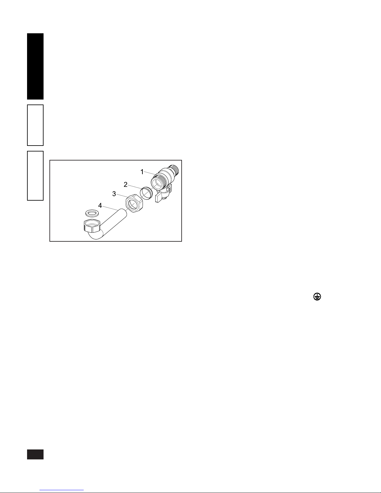
Ensure correct gas cock connection as shown in the assembly
sequence shown in the gure.
e gas supply pipe must be suitably dimensioned according
to current regulations in order to guarantee correct gas ow
to the boiler even in conditions of max. generator output
and to guarantee appliance eciency (technical data). e
coupling system must conform to standards.
Combustible gas quality. e appliance is designed to
operate on gas free of impurities; otherwise it is advisable
to t special lters ahead of the appliance for restoring the
purity of the gas.
Storage tanks (in case of supply from LPG depot).
- New LPG storage tanks may contain residuals of inert
gases (nitrogen) that impoverish the mixture delivered to
the appliance, causing anomalous operation.
- Due to the composition of the LPG mixture, layering
of the mixture components may occur during the period
of storage in the tanks. is can cause a variation in the
heating power of the mixture delivered to the appliance,
with subsequent change in its performance.
Water connection.
Important: before carrying out the boiler connections all the
system pipes must be carefully cleaned with special descaling
products for removing any deposits that could compromise
correct boiler operation.
In order to prevent scale forming in the heating system, the
provisions given in the regulations on water treatment in
heating systems for civil use must be respected.
Water connections must be made in a rational way using the
connections on the boiler template. e boiler safety valve
outlet must be connected to a discharge funnel. Otherwise,
the manufacturer declines any responsibility in case of ooding if the drain valve cuts in.
Important: to preserve the life and eciency of the domestic
circuit exchanger, it is advisable to install the “polyphosphate
dispenser” kit if the water has characteristics can give rise to the
forming of scale (in particular, the kit is recommended when the
water hardness is higher than 25 degrees French).
Condensate drain. To drain the condensate produced by
the appliance, it is necessary to connect to the drainage system by means of acid condensate resistant pipes having an
internal diameter of at least 13 mm. e appliance drainage
connection system must be executed in such a way as to
prevent freezing of the liquid contained in it. Before appliance start-up, ensure that the condensate can be correctly
removed. Also, comply with national and local regulations
on discharging waste waters.
Electrical connection. e entire “Victrix” boiler has IPX4D
protection rating. Electrical safety of the appliance is only
guaranteed when it is correctly connected to an ecient
earthing system according to current safety standards.
Important: Immergas S.p.A. declines any responsibility for
damage to persons or things caused by failure to connect
the boiler to an earthing system or non-compliance with
the reference standards
Also ensure that the electrical system is suitable for the
maximum power absorbed by the appliance, specied on
the boiler dataplate. Boilers are supplied complete with
an “X” type power cable without plug. e power cable
must be connected to a 230V ±10% / 50Hz mains supply
respecting the polarity L-N and earth connection ; the
mains power supply must also be equipped with a multi-pole
circuit breaker with contact opening gap of at least 3 mm.
When replacing the power supply cable, contact a qualied
technician (e.g. Immergas Authorized Technical Assistance
Service). e power cable must be laid as shown.
In the event of mains fuse replacement on the control card,
use a 3.15A quick-blow fuse. Never use adapters, multiple
sockets or extension leads for the main power supply to the
appliance.
If correct L-N polarity is not respected during connection,
the boiler will not detect the ame and inhibits start-up.
Important: also, whenever L-N polarity is not respected, if
the neutral is live with temporary residual voltage over 30V,
the boiler could operate just the same (but only temporarily).
Measure the voltage with suitable instruments; do not use a
phase tester screwdriver.
Key:
1 - Gas cock
2 - Biconical ring Ø 18
3 - Nut
4 - Gas pipe
4
INSTALLERUSERTECHNICIAN
5
INSTALLERUSERTECHNICIAN
Page 6
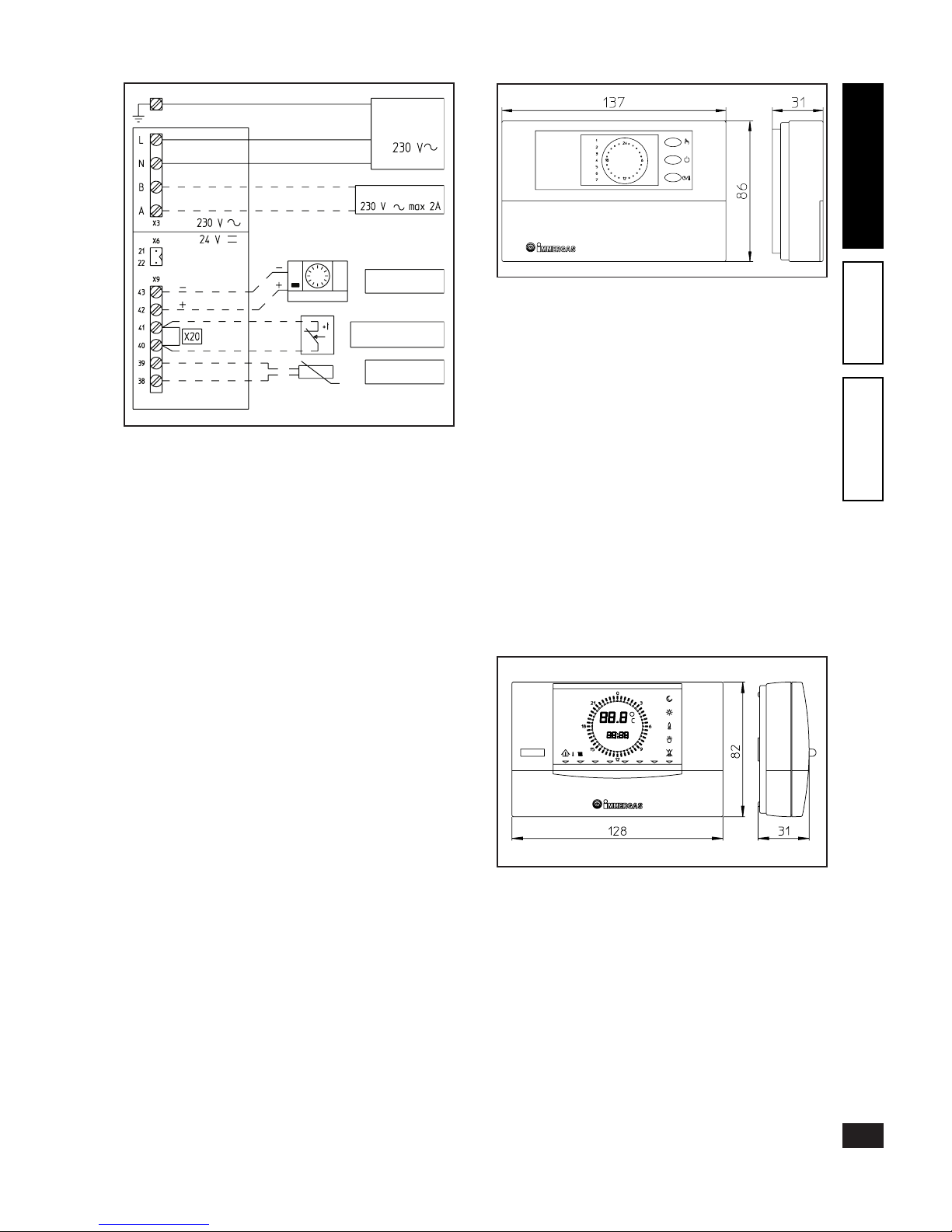
Room chronothermostats and external sensor (Optional).
e boiler is arranged for application of room chronothermostats and external sensor.
ese Immergas components are available as separate kits to
the boiler and are supplied by request.
All Immergas chronothermostats are connectable with 2
wires only. Carefully read the use and assembly instructions
contained in the accessory kit.
• On/O digital chronothermostat. e chronothermostat
enables:
- setting of two room temperature values: one for day
(comfort temperature) and one for night (lower
temperature);
- setting up to three on/o dierential weekly programs;
- selecting the required function mode from the various
possible alternatives:
• permanent operation in comfort temp;
• permanent operation in lower temp;
• permanent function in adjustable antifreeze temp.
e chronothermostat is powered by two 1.5V LR6 type
alkaline batteries.
• Remote Friend Contr ol Dev ice wi th climatic
chronothermostat function. In addition to the functions
described in the previous point, the Remote Friend
Control enables the user to have under control and at
hand all the important information regarding appliance
and heating system operation with the possibility of easily
changing the previously set parameters without having to
go to the place where the appliance is installed. e Remote
Friend Control panel is provided with self-diagnosis to
display any boiler operation anomalies. The climate
chronothermostat incorporated in the remote panel
enables the system delivery temperature to be adjusted
to the actual room heating needs, in order to obtain the
desired room temperature with extreme precision and
therefore with clear savings in running costs. It also enables
the room temperature and actual external temperature
(if the external sensor is present) to be displayed. e
chronothermostat is fed directly by the boiler by means of
the same 2 wires used for the transmission of data between
boiler and chronothermostat.
Power
supply
Auxiliary output
Remote control
(OPTIONAL)
On-Off Room Stat
(OPTIONAL)
External sensor
(OPTIONAL)
5
INSTALLERUSERTECHNICIAN
Page 7
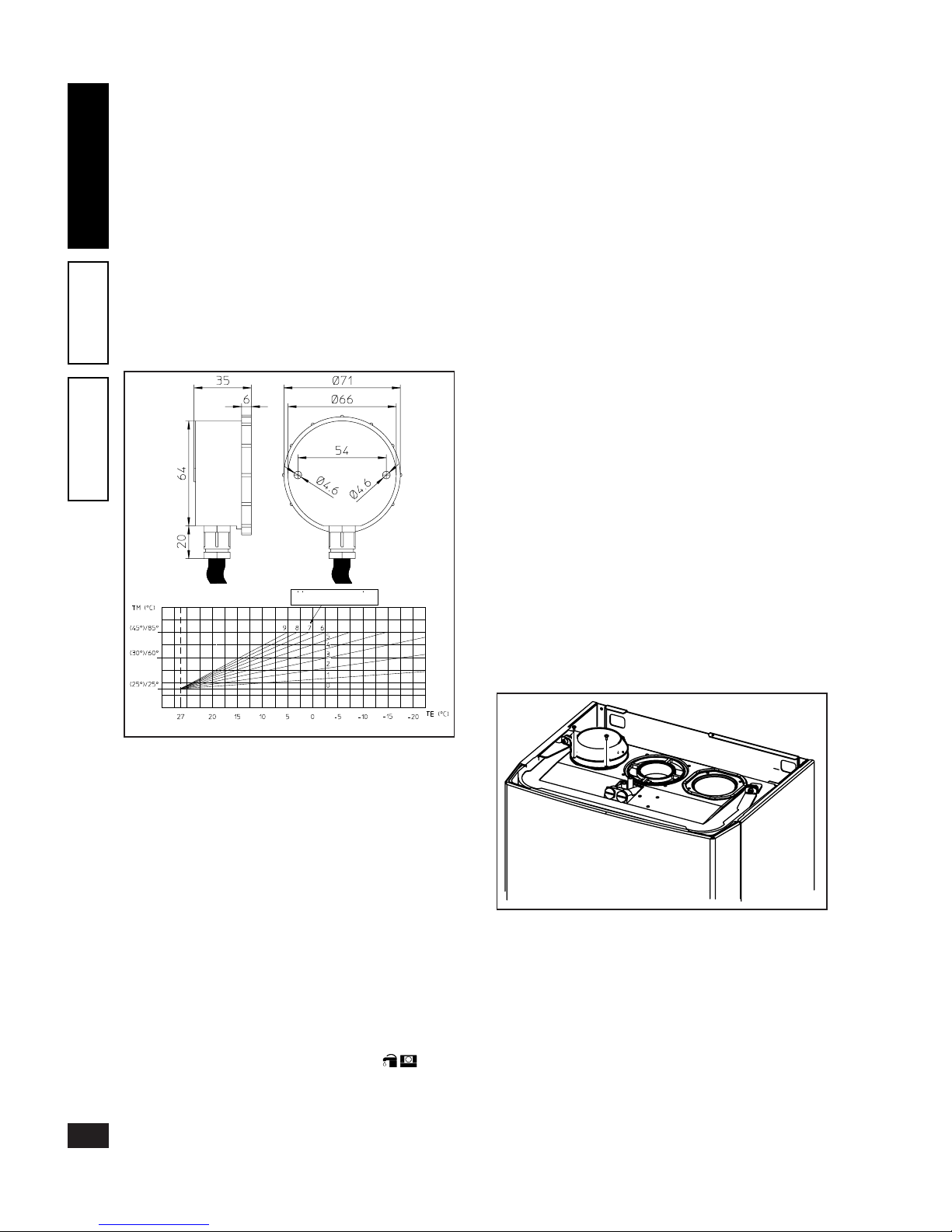
• External temperature sensor. is sensor can be connected
directly to the boiler electrical system and allows the max.
system delivery temperature to be automatically decreased
when the outside temperature increases, in order to adjust
the heat supplied to the system according to the change
in the outside temperature. e external sensor always
operates when connected, regardless of the presence or
type of room chronothermostat used, and can work in
combination with both Immergas chronothermostats.
e correlation between system delivery temperature and
outside temperature is determined by the position of the
knob on the boiler control panel according to the curves
shown in the diagram. e external sensor electrical connection must be made to terminals 38 and 39 on the boiler
electronic card (see g. page 5).
Electrical connection of the Remote Friend Control or
On/Off chronothermostat (Optional). The following
operations must be carried out after disconnecting the
electrical power supply; the possible thermostat or On/O
room chronothermostat must be connected to terminals 40
and 41 eliminating jumper X20 (see g. page 5). Make sure
the On/O thermostat contact is of the “clean” type, i.e.
separate from the mains supply, otherwise the electronic
adjustment card would be damaged. e possible Remote
Friend Control must be connected by means of terminals
IN+ and IN- to terminals 42 and 43 on the electronic card
(in the boiler) respecting the polarity, (see g. page 5);
connection with the wrong polarity inhibits its operation,
but without damaging the Remote Friend Control. After
connecting to the Remote Friend Control, jumper X20 must
be eliminated. e boiler works with the parameters set on
the Remote Friend Control only if the boiler main switch is
turned to Domestic/Remote Friend Control ( ).
Important: If the Remote Friend Control is used arrange
two separate lines in compliance with current regulations
regarding electrical systems. Boiler pipes must never be used
to earth the electrical or telephone system. Ensure this does
not occur, before making the boiler electrical connections.
Installation with system operating at low temperature.
e boiler can directly feed a low temperature system, by
operating on jumper (5) and setting the delivery temperature
range from 45°-25°C (as described on page 27). In this mode
it is advisable to include a safety in series with the boiler
circulating pump, formed of a thermostat having a limit
temperature of 55 °C. e thermostat must be positioned
on the system delivery pipe at more than 2 metres from the
boiler.
1.4 Boiler installation - B23 type with open chamber
and forced draught (optional).
In this conguration it is necessary to use the special terminal
(included in the special intake kit) to be tted on the intake
hole on the sealed chamber (see the following g.). Air is
drawn directly from the place where the boiler is installed,
and fumes are exhausted into a single ue or directly to the
outside. In this conguration, following the assembly instructions given on the relevant instruction sheet, the boiler
is classied as B
23
type.
With this conguration:
- air is drawn directly from the place where the appliance is
installed (which must only be in permanently ventilated
rooms).
- the fume exhaust must be connected to its own single ue
or ducted directly to the outside.
There fore the current technical standa rds must be
respected.
Max. length of exhaust ue. To avoid problems of fume
condensation due to cooling through the wall, the exhaust
duct can be extended up to a max. length of 30 m.
6
INSTALLERUSERTECHNICIAN
7
INSTALLERUSERTECHNICIAN
Page 8
1.5 Air intake and fume exhaust terminal installation.
Immergas supplies various solutions separately from the
boilers for the installation of air intake and fume exhaust
terminals necessary for boiler operation.
Important: the boiler must only be installed together with
an original Immergas “Green Range” air intake and fume
extraction system in plastic, as required by current regulations. is system is identiable by a special distinctive
marking giving the note: “for condensing boilers only”.
Important:
- for C1 type installation with doubled terminals, these must
be installed inside a 50 cm square perimeter;
- for C3 type installation the terminals must be installed
inside a 50 cm square perimeter and the distance between
the two levels of the openings must be less than 50 cm;
- for C5 type installation the two terminals must not be
installed on opposite walls of the building.
• Resistance factors and equivalent lengths. Each fume extraction system component has a resistance factor obtained
from preliminary tests and specied in the table below. e
resistance factor of the single component does not depend
on the type of boiler on which it is installed and is a dimensional value. It is based on the temperature of uids passing
through the ducts and therefore varies according to use in
air intake or fume exhaust. Each single component has a
resistance corresponding to a certain length in metres of
pipe of the same diameter: the so-called equivalent length.
All boilers have an experimentally obtainable maximum
Resistance Factor equal to 100. e maximum permissible
resistance factor corresponds to the resistance detected with
the maximum permissible pipe length with each type of
Terminal Kit. is information enables calculations for
verifying the possibility of executing a wide range of fume
extraction system congurations.
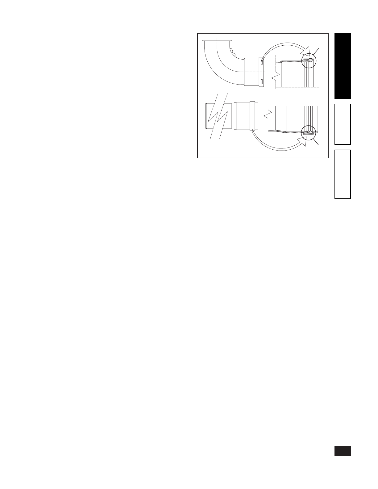
Positioning of seals (black) for “Green Range” fume extraction system. Make sure to correctly place the seal (for
bends or extensions) as shown in the gure:
- seal (A) with notches, to be used for bends;
- seal (B) without notches, to be used for extensions;
N.B.: if the lubrication of the components (already carried
out by the manufacturer) is insucient, remove the residual
lubricant using a dry rag, then cover the parts with normal
or industrial talc to facilitate coupling.
(A)
(B)
7
INSTALLERUSERTECHNICIAN
Page 9
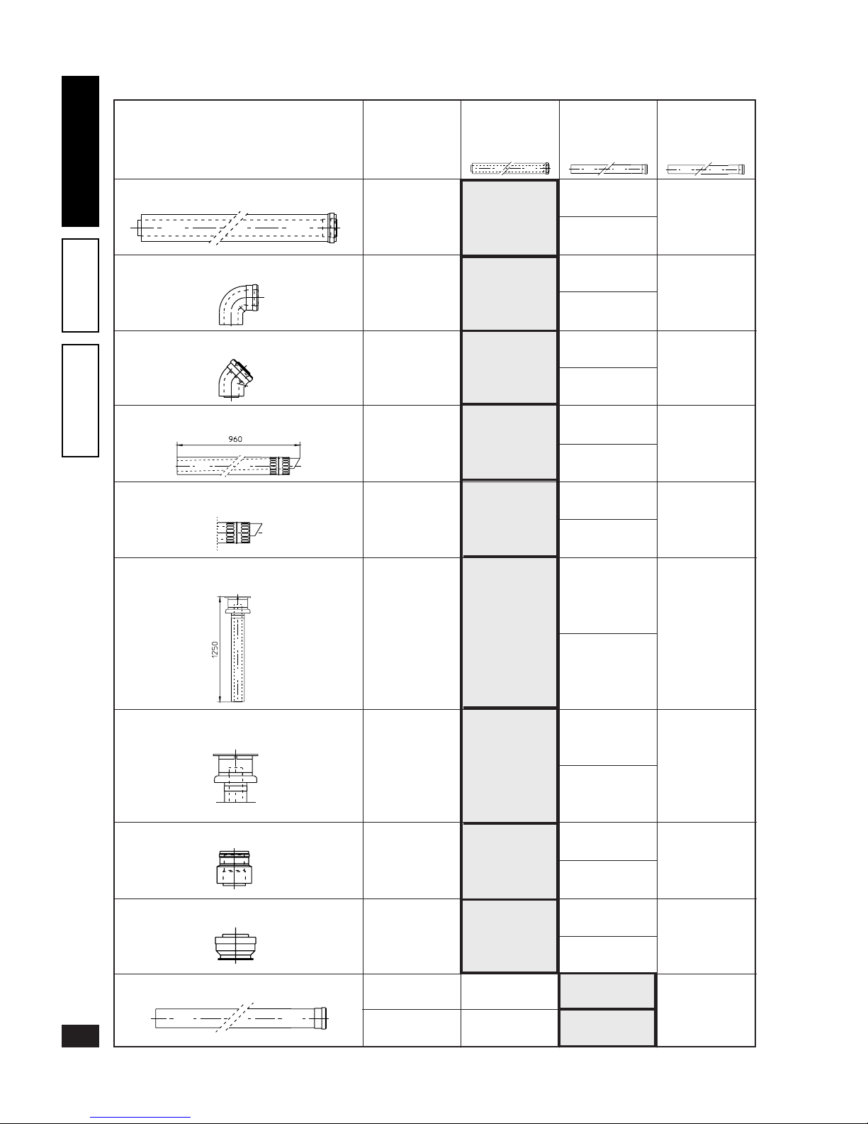
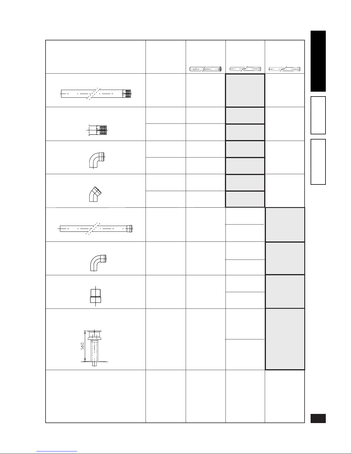
Resistance factor and equivalent length tables.
TYPE OF DUCT
Resistance
factor
(R)
Equivalent length
in metres of
concentric pipe
Ø 60/100
Equivalent
length in metres
of pipe
Ø 60
Concentric pipe Ø 60/100 length 1 m
90° bend concentric Ø 60/100
45° bend concentric Ø 60/100
Terminal complete with concentric
horizontal intake-exhaust Ø 60/100
Intake
and
exhaust
6.4
1 m
Intake
and
exhaust
8.2
1.3 m
Intake
and
exhaust
6.4
1 m
Intake
and
exhaust
15
2.3 m
Intake
and
exhaust
16.3
2.5 m
Exhaust
1.9 m
Exhaust
2.5 m
Exhaust
1.9 m
Exhaust
4.5 m
Exhaust
3.0 m
1.5 m
Intake
and
exhaust
10
Terminal complete with concentric
horizontal intake-exhaust Ø 60/100
Intake
and
exhaust
9
1.4 m
Intake
and
exhaust
5.2
0.8 m
Equivalent
length in metres
of pipe
Ø 80
Terminal complete with concentric
vertical intake-exhaust Ø 60/100
Concentric adapter from Ø 80/125 to 60/100
Terminal complete with concentric
vertical intake-exhaust Ø 60/100
Intake
7.3 m
Intake
9.4 m
Intake
7.3 m
Intake
17.2 m
Intake
18.7 m
Exhaust
5.3 m
Exhaust
6.8 m
Exhaust
5.3 m
Intake
11.5 m
Exhaust
12.5 m
Exhaust
8.3 m
Exhaust
13.6 m
Exhaust
1.6 m
Intake
6.0 m
Exhaust
4.3 m
Exhaust
4.9 m
Exhaust
2.7 m
Intake
10.3 m
Exhaust
7.5 m
Concentric ange Ø 80/125
Intake
and
exhaust
1.3
0.2 m
Exhaust
0.4 m
Intake
1.5 m
Exhaust
1.1 m
Pipe Ø 80 length 1 m
Intake
1.0 m
Exhaust
1.0 m
Exhaust
0.4 m
0.1 m
0.2 m
Intake
0.87
Exhaust
1.2
8
INSTALLERUSERTECHNICIAN
9
INSTALLERUSERTECHNICIAN
Page 10
TYPE OF DUCT
Resistance
Factor
(R)
Exhaust
0.5 m
Exhaust
1.1 m
Exhaust
3.5
0.55 m
0.35 m
Exhaust
0.6 m
Exhaust
0.8 m
Exhaust
1.0 m
0.3 m
Resistance factor and equivalent length tables.
Exhaust
3.7 m
Exhaust
12.2
1.9 m
Intake terminal Ø 80
Exhaust terminal Ø 80
90° bend Ø 80
45° bend Ø 80
Pipe 1 m Ø 60 for ducting
90° bend Ø 60 for ducting
Equivalent
length in metres of
concentric pipe
Ø 60/100
Equivalent
length in metres
of pipe
Ø 60
Equivalent
length in metres
of pipe
Ø 80
Complete vertical exhaust
terminal Ø 60 for ducting
Intake
2.2
Exhaust
1.9
Intake
1.9
Exhaust
2.6
Intake
1.2
Exhaust
1.6
Exhaust
3.3
0.4 m
0.2 m
0.25 m
0.5 m
Intake
1.4 m
Exhaust
1.3 m
Intake
2.5 m
Exhaust
1.6 m
Intake
2.2 m
Exhaust
2.1 m
Intake
3.8 m
Exhaust
2.7 m
Intake
4.0 m
Exhaust
2.9 m
Intake
14 m
0.3 m
0.5 m
Complete intake terminal Ø 80 length 1 m
Intake
3
Exhaust
0.9 m
Intake
3.4 m
Exhaust
10.1 m
Intake
and
exhaust
2.6
0.4 m
Exhaust
0.8 m
Intake
3.0 m
Exhaust
2.1 m
Adapter Ø 80/60
9
INSTALLERUSERTECHNICIAN
Page 11
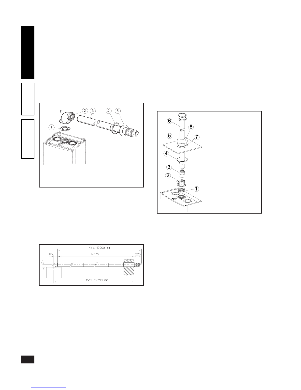
Horizontal intake kits - exhaust Ø 60/100.
Kit assembly: install the bend with ange (2) on the central
hole of the boiler inserting the seal (1) (which does not require
lubrication), positioning it with the round protrusions downwards in contact with the boiler ange and tighten using the
screws supplied with the kit. Fit the male end (smooth) of
the Ø 60/100 concentric terminal pipe (3) up to the stop
on the female end of the bend (2), making sure the relevant
internal and external rings are tted; this will ensure hold
and joining of the elements making up the kit.
N.B.: for correct operation of the system the terminal with
grill must be correctly installed, respecting the indication
“top” on the terminal.
• Coupling extension pipes and concentric elbows Ø 60/
100. To install possible coupling extensions on other fume
extraction elements, proceed as follows: t the male end
(smooth) of the concentric pipe or concentric elbow up to
the stop on the female end (with lip seals) of the previously
installed element; this will ensure correct hold and joining
of the elements.
e Ø 60/100 kit can be installed with the rear, right side,
left side and front outlet.
• Extensions for horizontal kit. e horizontal intake-ex-
haust kit Ø 60/100 can be extended up to a max. horizontal
length of 12.9 m, including the grill terminal and excluding
the concentric bend leaving the boiler. is conguration
corresponds to a resistance factor of 100. In this case special
extensions must be requested.
N.B.: when installing the ducts, a section clamp with pin
must be installed every 3 metres.
• External grill. N.B.: for safety purposes, do not even
temporarily obstruct the boiler intake/exhaust terminal.
Vertical kit with aluminium tile Ø 60/100.
Kit assembly: install the concentric ange (2) on the central
hole of the boiler inserting the seal (1) (not requiring lubrica-
tion), positioning it with the round protrusions downwards
in contact with the boiler ange and tighten using the screws
supplied with the kit. Fit the male end (smooth) of the
adapter (3) in the female end of the concentric ange (2).
Fake aluminium tile installation: replace the tiles with the
aluminium sheet (5), shaping it to ensure that rainwater runs
o. Position the xed half-shell (7) on the aluminium tile
and insert the intake/exhaust pipe (6). Fit the male end (6)
(smooth) of the Ø 60/100 concentric terminal up to the stop
on the female end of the adapter (3) (with lip seals), making
sure that the ring (4) is already tted; this will ensure hold
and joining of the elements making up the kit.
• Coupling extension pipes and concentric elbows. To install
possible coupling extensions on other fume extraction elements, proceed as follows: t the male end (smooth) of
the concentric pipe or concentric elbow up to the stop on
the female end (with lip seals) of the previously installed
element; this will ensure correct hold and joining of the
elements.
Important: if the exhaust terminal and/or extension concentric pipe needs shortening, consider that the internal
duct must always protrude by 5 mm with respect to the
external duct.
is specic terminal enables fume exhaust and air intake
necessary for combustion, in a vertical direction.
N.B.: the vertical kit Ø 60/100 with aluminium tile enables
installation on terraces and roofs with maximum slope of
45% (24°) and the height between the terminal cap and
half-shell (374 mm) must always be respected.
C13x
C13x
C33x
e kit comprises:
1 - Seal (1)
1 - Concentric bend Ø 60/100 (2)
1 - Concentric intake/exhaust
terminal Ø 60/100 (3)
1 - Internal ring (4)
1 - External ring (5)
e kit comprises:
1 - Seal (1)
1 - Female concentric ange (2)
1 - Adapter from 80/125
to 60/100 (3)
1 - Ring (4)
1 - Aluminium tile (5)
1 - Intake/exhaust concentric
pipe Ø 60/100 (6)
1 - Fixed half-shell (7)
1 - Movable half-shell (8)
10
INSTALLERUSERTECHNICIAN
11
INSTALLERUSERTECHNICIAN
Page 12

e vertical kit with this conguration can be extended to a
max. vertical length of 13.4 m, including the terminal. is
conguration corresponds to a resistance factor of 100. In
this case specic extensions must be requested.
Separator kit Ø 80/80. e separator kit Ø 80/80, enables
separation of the exhaust ues and air intake pipes according to the layout shown in the gure. Fumes are expelled
from duct (A) (strictly in plastic material resistant to acid
condensates). Air is taken in through duct (B) (also in plastic
material) for combustion. Intake duct (B) can be installed
either on the right or left hand side of the central exhaust
duct (B). Both ducts can be oriented in any direction.
• Assembly of separator kit Ø 80/80. Install the ange (4)
on the central hole of the boiler inserting the seal (1)
(which does not require lubrication), positioning it with the
round protrusions downwards in contact with the boiler
ange and tighten using the screws supplied with the kit.
Remove the at ange on the lateral hole (depending on
installation requirements) and replace it with ange (3)
inserting seal (2) already tted on the boiler and tighten
using the screws supplied. Insert bends (5) with the male
end (smooth) in the female end of the anges (3 and 4).
Fit the male end (smooth) of the intake terminal (6) up to
the stop on the female end of the bend (5), making sure
that the relevant internal and external rings are tted. Fit
the male end (smooth) of the exhaust pipe (9) up to the
stop on the female end of the bend (5), making sure that
the internal ring is tted; this will ensure hold and joining
of the elements making up the kit.
• Coupling of extension pipes and elbows. To install possible
coupling extensions on other fume extraction elements,
proceed as follows: t the male end (smooth) of the pipe
or elbow up to the stop on the female end (with lip seals)
of the previously installed element; this will ensure correct
hold and joining of the elements.
• Installation space. e previous gure gives the min.
installation space dimensions of the Ø 80/80 separator
terminal kit in several limit conditions.
• Extensions for separator kit Ø 80/80 e max. vertical
straight length (without bends) usable for Ø 80 intake
and exhaust pipes is 41 metres regardless of whether they
are used in intake or exhaust. e max. horizontal straight
length (with intake and exhaust bends) usable for Ø 80
intake and exhaust pipes is 36 metres regardless of whether
they are used in intake or exhaust.
N.B.: to favour the removal of possible condensate forming
in the exhaust pipe, incline the pipes towards the boilers
with a min. slope of 1.5% (see g.). When installing the Ø
80 ducts, a section clamp with pin must be installed every
3 metres.
e kit comprises:
1 - Exhaust seal (1)
1 - Flange seal (2)
1 - Female intake ange (3)
1 - Female exhaust ange (4)
2 - Bends 90° Ø 80 (5)
1 - Intake terminal Ø 80 (6)
2 - Internal rings (7)
1 - External ring (8)
1 - Exhaust pipe Ø 80 (9)
C33x
C83x
C43x
11
INSTALLERUSERTECHNICIAN
Page 13

Internal installation in B23 conguration.
The appliance can be installed inside buildings in B23
configuration; in this case, make sure to respect all
the technical standards and current national and local
regulations(see page 6).
1.6 Ducting existing ues.
Ducting is an operation through which, within the context
of restructuring a system and with the introduction of one or
more special ducts, a new system is executed for evacuating
the fumes of a gas appliance, starting from an existing ue
(or a chimney) or a technical hole. Ducting requires using
conduits declared suitable for the purpose by the manufacturer, following the installation and operation instructions
provided by the manufacturer, and the requirements of the
standard.
Immergas ducting system. “Green Range” Ø 60 mm rigid
and Ø80 exible ducting systems can only be used for domestic
use and with Immergas condensing boilers.
In any case, ducting operations must respect the provisions
contained in the standards and in current technical regulations; in particular, the declaration of conformity must be
compiled at the end of work and on commissioning of the
ducted system. e instructions in the project or technical
report must likewise be followed, in cases provided for by
the standard and current technical regulations. e system
or components of the system have a technical life complying
with current standards, provided that:
- it is used in average atmospheric and environmental conditions, according to current regulations (absence of fumes,
dusts or gases that can alter the normal thermophysical
or chemical conditions; existence of temperatures coming
within the standard range of daily variation, etc.).
C83x
C83x
12
INSTALLERUSERTECHNICIAN
13
INSTALLERUSERTECHNICIAN
Page 14

- Installation and maintenance are performed according
to the manufacturer’s instructions and the provisions of
current regulations.
- e max. possible length of the Ø 60 rigid ducting vertical section is 22 m is length is obtained considering
the complete Ø 80 intake terminal, 1m of Ø 80 pipe in
exhaust, two 90° Ø 80 bends at boiler outlet.
- e max. possible length of the Ø 80 exible ducting
vertical section is equal to 30 m. is length is obtained
considering the complete Ø 80 intake terminal, 1m of
Ø 80 pipe in exhaust, two 90° Ø 80 bends at boiler outlet
for connecting to the ducting system and two direction
changes of the flexible tube inside the flue/technical
hole.
1.7 Fume exhaust to ue/chimney.
e fume exhaust does not have to be connected to a conventional
type branched ue. e fume exhaust can be connected to a
special LAS type multiple ue. Multiple ues and combined
ues must also only be connected to type C appliances
and of the same category (condensing), having rated heat
outputs not diering by less than 30% with respect to the
max. connectable and fed by the same type of fuel. e
thermofluidodynamic characteristics (flowrate in mass
of fumes, % of CO2, % humidity, etc.) of the appliances
connected to the same multiple or combined ues must
not dier by more than 10% with respect to the average
boiler connected. Multiple and combine ues must be
specially designed according to the calculation method and
requirements of the standards, by professionally qualied
technical personnel. Chimney or ue sections for connection
of the exhaust pipe must comply with requirements of the
standards.
1.8 Chimneys/ues.
General details. A chimney/ue used to exhaust fumes
must:
- in case of wet operation, be made of materials suitable for
discharging the condensate in compliance with the provisions
of current standards and regulations;
- be fumetight, waterproof and insulated;
- be made from reproof materials ensuring lasting resistance
to normal mechanical stress, heat and the action of fumes
and their possible condensate;
- have a vertical path without any constrictions;
- be adequately separated, by means of a suitable air space
or insulation, from zones with combustible and/or easily
ammable materials;
- be suitably designed to prevent the possible freezing of
condensate inside the fume system and condensate discharge system (trap, passivator tank);
- comply with the current relevant national and local regulations, for discharge of the condensate produced by the
fume exhaust system;
- have a solid materials and possible condensate collection
unit below the opening of the rst ue at a height of at least
500mm, tted with an airtight metal door;
- have have a round, square or rectangular internal section
(in the latter two cases, with rounded angles and radius of
not less than 20 mm). Hydraulically equivalent sections
are also allowed;
- have a chimney-top in compliance with the specications
given below;
- be without mechanical extraction devices installed at the
top of the duct;
- in ues routed inside or against inhabited buildings, there
must be no risk of pressure surges.
Chimney-tops. A chimney-top is the device generally installed on top of single or multiple ues. is device facilitates
the dispersion of fumes also in adverse weather conditions
and prevents depositing of foreign matter. It must:
- have a useful outlet section not less than double that of
the ue/chimney on which it is installed;
- be suitably designed to prevent the entry of rain or snow
in the ue/chimney;
- be shaped in such as way that prevents the formation of
frost and ice at the free outlet sections;
- be designed to ensure constant exhaust of combustion
products with any wind direction or angle.
e outlet height, corresponding to the height of the top
of the ue/chimney, regardless of any chimney-tops, must
be outside the “backow zone”, to avoid the risk of counterpressures that prevent the free release of fumes into the
atmosphere. erefore always respect the minimum heights
given in the gures for standards, according to the pitch.
Positioning of draught terminals. Draught terminals must:
- be installed on external outer walls of the building;
- be positioned according to the minimum distances specied in current technical standards.
Fume exhaust of forced draught appliances in closed
open-top environments. In spaces closed on all sides
with open tops (ventilation pits, courtyards etc.), direct
fume exhaust is allowed for natural or forced draught gas
appliances with a heating power range from 4 to 35 kW,
provided the conditions as per the current technical standards
are respected.
13
INSTALLERUSERTECHNICIAN
Page 15

1.9 Filling of system.
After the boiler is connected, ll the system by means of
the ller cock (see g. page 16, 17 and 20). Filling must be
done slowly to ensure the release of air bubbles in the water
through the boiler and heating system relief valves.
e boiler has a built-in automatic air valve on the expansion
tank, located on the side of the sealed combustion chamber.
Check that the cap is loosened. Open the relief valves on the
radiators. Close the relief valves when only water comes out.
Close the ller cock when the boiler pressure gauge indicates
approx. 1.2 bar.
N.B.: During this operation, start the circulating pump at
intervals by means of the main switch on the control panel.
Vent the circulating pump by unscrewing the front cap and keeping the motor running. Tighten the cap on completion.
1.10 Condensate trap lling.
With the rst boiler lighting fumes may come out the
condensate drain; after a few minutes’ operation check that
fumes no longer come out. is means that the trap is lled
with condensate to the correct level thus preventing the
passage of fumes.
1.11 Gas system start-up.
To start up the system proceed as follows:
- open windows and doors;
- avoid the presence of sparks or naked ames;
- vent all air from pipelines;
- check gas supply tightness with the boiler gas ON/OFF
cock closed; no gas ow must be indicated on the meter
for 10 minutes.
1.12 Boiler start-up (lighting).
For issue of the Declaration of Conformity provided for by
Italian Law, the following must be done for boiler start-up:
- check gas supply circuit tightness with the 0n/O valve
closed and subsequently open with gas valve closed; no gas
ow must be read on the meter for 10 minutes;
- ensure that the type of gas used corresponds to that for
which the boiler is arranged;
- switch on the boiler and ensure correct ignition;
- make sure that the gas owrate and relevant pressure values
comply with those given in the manual (see page 32);
- ensure that the safety device activates in the event of no gas
and check activation time;
- check activation of the main switch generally located ahead
of the boiler and on the unit;
- check that the concentric intake/exhaust terminal (if tted)
is not blocked.
e boiler must not be started up in the event of negative
result of any of the above checks.
Preliminary boiler testing must be performed by a qualied technician. e boiler warranty is valid as of the date of testing.
e test and warranty certicate is issued to the user.
1.13 Circulating pump.
“Victrix” range boilers are supplied with a built-in circulating
pump with 3 or 4-position electric speed control (depending
on the circulating pump). e boiler does not operate
correctly with the circulating pump on rst and second
speed. To ensure optimal boiler operation, with new systems
(single pipe and modul) it is advisable to use the circulating
pump at maximum speed. e circulating pump is already
tted with a capacitor.
Pump release. If, after a prolonged period of inactivity, the
circulating pump is blocked, unscrew the front cap and turn
the motor shaft using a screwdriver. Take great care during
this operation, to avoid damaging the motor.
14
INSTALLERUSERTECHNICIAN
15
INSTALLERUSERTECHNICIAN
Page 16

1.14 Kits available by request.
• System on/o cock kit (by request). e boiler is arranged
for installation of system on/o cocks to be placed on the
delivery and return pipes of the connection assembly. is
kit is particularly useful for maintenance as it allows the
boiler to be drained separately without having to empty
the entire system.
Head available at system - Victrix 20.
A = Head available at system at max. speed with by-pass cut out (adjustment screw fully screwed down)
B = Head available at system at max. speed (screw tightened 4.5 turns with respect to the adjustment screw fully unscrewed)
C = Head available at system at max. speed with by-pass open (adjustment screw fully unscrewed)
Head (kPa)
A
Flowrate l/h
B
C
Head (m H
2
O)
• Polyphosphate dispenser kit (by request). e polyphosphate dispenser prevents the formation of scale and
preserves the original heat exchange and domestic hot
production water conditions. e boiler is arranged for
application of the polyphosphate dispenser kit.
e above kits are supplied complete with instructions for
assembly and use.
Head available at system - Victrix 27.
Flowrate (l/h)
A = Head available at system at max. speed with by-pass cut out (adjustment screw fully screwed down)
B = Head available at system at max. speed with by-pass cut out (screw tightened 4.5 turns with respect to adjustment screw the fully unscrewed)
C = Head available at system at max. speed with by-pass open (adjustment screw fully unscrewed)
Head (kPa)
A
B
C
Head (m H
2
O)
15
INSTALLERUSERTECHNICIAN
Page 17

1.15 Boiler components - Victrix 20.
Key:
1 - Gas valve
2 - Condensate trap
3 - Domestic circuit adjustment NTC sensor
4 - Sealed chamber back
5 - Igniter sensor
6 - Condensing module cover
7 - Intake points (air A) - (fumes F)
8 - NTC limit and heating control sensor
9 - Condensing module
10 - Igniters
11 - Air intake pipe
12 - Sleeve with seat for Venturi
13 - Electronic control unit
14 - Overtemperature safety thermostat
15 - Circulating pump
16 - Plate-type heat exchanger
17 - Pump safety pressure switch
18 - 3 bar safety valve
19 - 3-way valve monobloc
20 - Automatic by-pass
21 - System drain cock
22 - System ller cock
23 - Current transformer
24 - Air fan
25 - Expansion tank
26 - Air valve
27 - Fume extractor hood
28 - Positive signal pressure point
29 - Negative signal pressure point
30 - Burner
31 - Gas valve outlet pressure test
16
INSTALLERUSERTECHNICIAN
17
INSTALLERUSERTECHNICIAN
Page 18

1.16 Boiler components - Victrix 27.
Key:
1 - Gas valve
2 - Condensate trap
3 - Domestic circuit adjustment NTC sensor
4 - Sealed chamber back
5 - Igniter sensor
6 - Condensing module cover
7 - Intake points (air A) - (fumes F)
8 - NTC limit and heating control sensor
9 - Condensing module
10 - Igniters
11 - Air intake pipe
12 - Sleeve with seat for Venturi
13 - Electronic control unit
14 - Overtemperature safety thermostat
15 - Circulating pump
16 - Plate-type heat exchanger
17 - Pump safety pressure switch
18 - 3 bar safety valve
19 - 3-way valve monobloc
20 - Adjustable by-pass
21 - System drain cock
22 - System ller cock
23 - Current transformer
24 - Air fan
25 - Expansion tank
26 - Vent valve
27 - Fume extractor hood
28 - Positive signal pressure point
29 - Negative signal pressure point
30 - Burner
31 - Gas valve outlet pressure tester
32 - Aqua Celeris
33 - Aqua Celeris resistance
17
INSTALLERUSERTECHNICIAN
Page 19

2
USE AND MAINTENANCE
INSTRUCTIONS
2.1 Cleaning and maintenance.
Important:e user must have the heating system serviced
at least once a year and a combustion test (fume test) carried
out at least once every two years.
This ensures that the optimal safety, performance and
operation characteristics of the boiler remain unchanged
over time.
We recommend stipulating a yearly cleaning and maintenance
contract with your area technician.
2.2 General instructions.
Never expose the wall-mounted boiler to direct vapours
from cook-tops.
The boiler must not be used by unskilled persons or
children.
For safety purposes, ensure that the concentric air intake/
fume exhaust terminal (if tted) is not even temporarily
blocked.
If temporary shutdown of the boiler is required, proceed
as follows:
a)drain the water system if anti-freeze is not used;
b)shut-o all electrical, water and gas supplies.
In case of work or maintenance to structures located in the
vicinity of ducting or fume extraction devices and relevant
accessories, switch o the appliance and after completion
of work have qualied personnel check the eciency of the
ducting or devices.
Do not clean the appliance or its parts with easily ammable
substances.
Do not leave containers or ammable substances in the same
room as the appliance.
• Important: the use of any component that uses electricity
involves compliance with several fundamental rules:
- do not touch the appliance with wet or moist parts of
the body; do not touch when barefoot;
- do not pull electrical cables or leave the appliance exposed
to atmospheric agents (rain, sunlight, etc.);
- the appliance power cable must not be replaced by the
user;
- in the event of damage to the cable, switch o the appliance and contact exclusively qualied personnel for
replacement;
- if the appliance is not used for a certain period, disconnect the main power switch.
18
INSTALLERUSERTECHNICIAN
19
INSTALLERUSERTECHNICIAN
Page 20

Boiler ignition. Before lighting, make sure the system is full
of water and that the manometer (6) indicates a pressure of
1÷1.2 bar.
- Open the gas cock downstream of the boiler.
Turn main switch (5) to Domestic/Remote Friend Control
( ) or Domestic and Heating ( ).
• Operation with Remote Friend Control (Optional). With
the switch (5) set to ( ) and Remote Friend Control
connected the boiler sensors (2) and (3) are cut out; the
wording “CE” (External Commands) appears on the display. e boiler adjustment parameters are settable from
the Remote Friend Control panel.
• Operation without Remote Friend Control. With the
switch (5) set to ( ) the heating adjustment selector (2) is cut out, and the domestic water temperature
is adjusted by selector (3). With the switch set to ( )
the heating adjustment selector (2) is used to regulate the
temperature of radiators, whereas selector (3) is used for
the domestic water. Turn the selectors clockwise to increase
the temperature, and anticlockwise to decrease it.
Boiler operation is now automatic. Every boiler ignition is
signalled by means of the indicator (9) on the control panel.
When the selector (2) or (3) is turned, the temperature setting at that moment is shown on the display (8), and at the
same time indicator (1) or (4) ashes, depending on the
selector being used; after 5 seconds the current boiler delivery
temperature value appears on the display (8).
Signalling and diagnostics - Display (8). During normal
boiler operation the boiler delivery temperature value is displayed. With the boiler on Stand-by an illuminated horizontal segment appears on the display. In case of malfunction
or anomaly, the temperature is replaced by the relative error
code ashing.
1 = Ignition block
2 = Block due to the overtemperature safety thermostat
activation
5 = Delivery sensor fault
6 = Domestic circuit sensor fault
10 = Failed water ow switch activation
14 = Flame control unit fault
16 = Fan fault
17= Fan rpm incorrect
26= Water ow switch fault
31 = Remote Friend Control not compatible
e user can reset boiler blocks signalled by codes 1 and 2,
by pressing the boiler reset pushbutton (7) or the reset button
on the Remote Friend Control (if connected); if the block
persists request the intervention of a qualied technician (eg.
Immergas Technical Assistance Service).
Boiler block signalled by code 10 can be due to: lack of water
in the system, blocked or faulty circulating pump. In the rst
case check that the pressure gauge (6) indicates a value of
1÷1.2 bar; in the latter two, call a qualied technician (e.g.
Immergas Technical Assistance Service).
All the other signals (codes: 5-6-14-16-17-26-31) require
the intervention of a qualied technician (e.g. Immergas
Technical Assistance Service).
Boiler shutdown. Turn o the main switch (5), turning it
to “0”, and close the gas cock ahead of the appliance.
Never leave the boiler switched on if not used for prolonged
periods.
Key:
1 - Heating On indicator
2 - Heating temperature selector
3 - Domestic hot water temperature selector
4 - Domestic hot water On indicator
5 - 0-Domestic/Remote Control-Domestic and Heating switch
6 - Boiler manometer
7 - Reset
8 - Temperature and diagnostics display
9 - Burner On indicator
2.3 Control panel
19
INSTALLERUSERTECHNICIAN
Page 21

2.4 Restoring heating system pressure.
Periodically check the system water pressure.
e boiler pressure gauge must read a pressure of between
1 and 1.2 bar.
If the pressure falls below 1 bar (with the system cold) restore
normal pressure by means of the cock located at the bottom of
the boiler (see g.).
N.B.: close the cock on completion.
If pressure values reach around 3 bar the safety valve may
be activated.
In this case contact professionally qualied personnel for
assistance.
In the event of frequent pressure drops, contact professionally
qualied personnel for assistance to eliminate the possible
system leak.
2.5 Draining the system.
To drain the boiler, use the special system drain connection
(see detail 21 page 16-17).
Before draining, ensure that the system filler cock is
closed.
2.6 Anti-freeze protection.
e boiler is equipped with an antifreeze function that starts
the pump and the burner when the system water temperature
inside the boiler falls below 4°C. e anti-freeze function is
guaranteed if the boiler is fully operative and not in “block”
status, and is electrically fed with the main switch set to
Summer or Winter. To avoid keeping the system operating in
the event of prolonged absence, the system must be drained
completely or anti-freeze products added to the heating system water. In both cases the boiler domestic water circuit
must be drained. In a system subject to frequent draining,
the system must be relled with suitably treated water to
eliminate hardness that can cause the forming of scale.
2.7 Casing cleaning.
Use damp cloths and neutral soap to clean the boiler casing.
Never use abrasive or powder detergents.
2.8 Decommissioning.
In the event of boiler decommissioning, contact professionally qualied personnel for the relevant operations and
ensure that the electrical, water and gas supply lines are
disconnected.
20
INSTALLERUSERTECHNICIAN
Page 22

3
BOILER STARTUP
PRELIMINARY CHECK
To start up the boiler, proceed as follows:
- ensure that the declaration of conformity of installation is
supplied with the appliance;
- check the gas supply circuit tightness with the 0n/O valves
closed and subsequently open with gas valve closed; no gas
ow must be indicated on the meter for 10 minutes.
- check that the type of gas used corresponds to that for
which the boiler is arranged;
- check connection to a 230V-50Hz power supply, correct
L-N polarity and the earthing connection;
- switch on the boiler and check correct ignition;
- check the CO2 in the fumes at max. and min. output;
- check that the maximum, intermediate and minimum gas
owrate and relative pressure values comply with those
given in the handbook on page 32;
- check activation of the safety device in the event of no gas,
and the relevant intervention time;
- check activation of the main switch ahead of the boiler
and on the unit;
- check that the intake and/or exhaust terminals are not
blocked;
- check activation of the regulation devices;
- seal the gas ow regulation devices (if the settings are
modied);
- check the production of hot domestic water;
- check the tightness of water circuits;
- check ventilation and/or airing of the installation room
where provided.
If any safety checks give negative results, do not start the
boiler.
Remote Friend Control or Room ermostat:
e boiler is arranged for application of a Room thermostat or the
Remote Friend Control (C.A.R.). Connect the Room ermostat to
terminals 40 and 41 and remove jumper X20. e Remote Friend
3.1 Wiring diagram - Victrix 20.
Control must be connected to terminals 42 and 43 of the electronic
card, respecting the polarity and removing jumper X20.
M2 - Fan
PU1 - “Block” reset
S1 - Main rotary switch
S2 - Pump ow microswitch
S3 - Domestic circuit priority microswitch
T1 - Voltage transformer
TA - Room thermostat On/O (optional)
U1 - Rectier inside the gas valve connector (present on Honeywell and Dungs gas valves)
X20 - Room thermostat or Remote Friend Control inhibitor jumper
Y1 - Gas valve
white
black
black
black
black
black
white
white
white
white
white
red
red
red
red
red
red
pink
pink
purple
brown
brown
orange
brown
brown
purple
purple
pink
orange
grey
grey
grey
grey
orange
gey-green
red-black
red-black brown
red-black
white-blue
white-blue
red-black
blue
blue
blue
N.B.
The rectifier U1 is present on boilers equipped
with Honeywell and Dungs gas valv
e
N.B.
The connectors edged in black are
inserted on the ignition unit
Power supply
Zone station
(optional)
IGNITION/
DETECTION
UNIT
ADJUSTMENT
CARD
DISPLAY CARD
Auxiliary
output
Key:
B1 - Heating NTC sensor
B2 - Domestic circuit NTC sensor
B3 - External sensor (optional)
CAR - Remote Friend Control (optional)
DL1 - Heating mode LED
DL2 - Domestic mode LED
DL3 - Flame presence LED
E1-E2 - Igniters
E3 - Igniter sensor
E4 - Temperature safety thermostat
M1 - Circulating pump
21
INSTALLERUSERTECHNICIAN
Page 23

Remote Friend Control or Room ermostat:
the boiler is arranged for application of a Room ermostat
(TA) or Remote Friend Control (CAR). Connect the Room
ermostat to terminals 40 and 41 and remove jumper X20.
e Remote Friend Control must be connected to terminals
42 and 43 on the electronic card, respecting the polarity and
removing jumper X20.
3.2 Wiring diagram - Victrix 27.
Key:
B1 - Heating NTC sensor
B2 - Domestic circuit NTC sensor
B3 - External sensor (optional)
CAR - Remote Friend Control (optional)
DL1 - Heating On LED
DL2 - Domestic circuit On LED
DL3 - Flame presence LED
E1-E2 - Igniters
E3 - Detection plug
E4 - Temperature safety thermostat
M1 - Circulating pump
M2 - Fan
PU1 - “Block” reset
R2 - Domestic circuit thermal ywheel PTC
S1 - Main rotary switch
S2 - Pump ow switch microswitch
S3 - Domestic circuit priority microswitch
T1 - Voltage transformer
TA - Room thermostat On/O (optional)
U1 - Rectier inside gas valve connector (present on Honeywell and Dungs)
X20 - Room thermostat or Remote Friend Control inhibitor jumper
Y1 - Gas valve
white
white
white
white
red
gey-green
pink
pink
pink
purple
purple
purple
red
red
red
white
white
red
grey
grey
brown
orange
brown
brown
brown
white-blue
white-blue
brown
red-black brown
blue
black
black
black
red-black
red-black
red-black
black
black
grey
grey
red
orange
orange
orange
blue
blue
blue
blue
N.B.
The rectifier U1 is present on boilers equipped
with Honeywell and Dungs gas valve
N.B.
The connectors edged in black
are inserted on the ignition unit.
ADJUSTMENT
CARD
IGNITION/
DETECTION
UNIT
DISPLAY CARD
Zone unit
(optional)
Auxiliary
output
Power supply
22
INSTALLERUSERTECHNICIAN
23
INSTALLERUSERTECHNICIAN
Page 24

3.3 Plumbing diagram - Victrix 20.
Key:
1 - Minimum owrate valve
2 - Flow limiter
3 - 3-way hydraulic valve
4 - Gas valve
5 - Condensate trap
6 - Domestic water heat exchanger
7 - Domestic circuit adjustment NTC sensor
8 - Air fan
9 - Gas nozzle
10 - Igniter sensor
11 - Burner
12 - Condensing module cover
13 - Condensing module
14 - Fume extractor hood
15 - p gas pressure point
16 - NTC limit and heating control sensor
17 - Overtemperature safety thermostat
18 - Automatic air valve
19 - Igniters
20 - Expansion tank
21 - Air intake pipe
22 - Circulating pump
23 - Circulating pump pressure switch microswitch
24 - One-way valve
25 - Circulating pump pressure switch
26 - 3 bar safety valve
27 - Automatic by-pass
28 - Domestic circuit ow switch microswitch
29 - Filler cock
30 - Air analyzer chamber
31 - Fume analyzer chamber
32 - Venturi negative signal (P2)
33 - Venturi positive signal (P1)
34 - Gas valve outlet pressure point (P3)
35 - Air/gas Venturi manifold
G - Gas supply
S - Condensate drain
U - Hot domestic water outlet
E - Domestic water inlet
R - System return
M - System delivery
23
INSTALLERUSERTECHNICIAN
Page 25

3.4 Plumbing diagram - Victrix 27.
Key:
1 - Minimum ow valve
2 - Flow limiter
3 - 3-way hydraulic valve
4 - Condensate trap
5 - Gas valve
6 - Domestic water heat exchanger
7 - Gas valve outlet pressure point (P3)
8 - Domestic hot water adjustment NTC sensor
9 - Venturi positive signal (P1)
10 - Air fan
11 - Venturi negative signal (P2)
12 - Gas nozzle
13 - Air/gas Venturi manifold
14 - Igniter sensor
15 - Burner
16 - Condensing module cover
17 - Condensing module
18 - Fume extractor hood
19 - Air analyzer chamber
20 - p gas pressure point
21 - Fume analyzer chamber
22 - NTC limit and heating control sensor
23 - Overtemperature safety thermostat
24 - Automatic air valve
25 - Igniters
26 - Expansion tank
27 - Air intake pipe
28 - Aqua Celeris
29 - Circulating pump
30 - Aqua Celeris resistance (PTC)
31 - Circulating pump pressure switch microswitch
32 - One-way valve
33 - Circulating pump pressure switch
34 - 3 bar safety valve
35 - Adjustable by-pass
36 - Domestic circuit ow switch microswitch
37 - Filler cock
G - Gas supply
S - Condensate drain
U - Domestic hot water outlet
E - Domestic water inlet
R - System return
M - System delivery
24
INSTALLERUSERTECHNICIAN
25
INSTALLERUSERTECHNICIAN
Page 26

3.5 Troubleshooting.
N.B.: maintenance must be performed by a qualied techni-
cian (e.g. Immergas Technical Assistance Service).
- Smell of gas. Caused by leakage from gas circuit pipes.
Check tightness of gas supply circuit.
- Repeated ignition blocks (error 1). is can be caused by:
incorrect electrical feed, check correct L and N polarity.
No gas, check pressure in mains and that the gas supply
cock is open. Incorrect gas valve adjustment, check correct
setting of gas valve.
- Irregular combustion or noisiness. is can be caused by:
dirty burner, incorrect combustion parameters, intakeexhaust terminal not correctly installed. Clean the above
components and check correct installation of the terminal,
check correct setting of the gas valve (O-Set setting) and
correct percentage of CO2 in fumes.
- Frequent activation of the overtemperature safety thermostat (error 2). is can be caused by lack of water in
the boiler, insucient water circulation in the system or
blocked circulating pump. Check on the pressure gauge
that values are within the xed limits. Check that radiator
valves are not all closed and that the circulating pump is
working correctly.
- Trap clogged (error 1). is can be caused by dirt or combustion products inside. By means of the condensate drain
plug check for any residuals of material possibly blocking
the ow of condensate.
- Exchanger blocked (error 1). is can be caused by the
trap being blocked. By means of the condensate drain plug
check for any residuals of material possibly blocking the
ow of condensate.
- Noise due to air in the system (error 10). Check opening of
the cap on the special air valve (see g. page 16-17). Check
that system pressure and the expansion tank precharge are
within the set limits. e expansion tank precharge value
must be 1.0 bar, and the system pressure between 1 and
1.2 bar.
3.6 Converting the boiler to another type of gas.
If the boiler has to be converted to a dierent gas type to that
specied on the dataplate, request the relative conversion kit
for quick conversion. Boiler conversion must be carried out
by a qualied technician (e.g. Immergas Technical Assistance
Service).
To convert to another type of gas the following operations
are required:
- replace the nozzle located between the gas pipe and gas/air
mixing sleeve (detail 9 page 23 or detail 12 page 24);
- adjust (if necessary) maximum boiler heat output;
- check the value of CO2 In the fumes with the boiler at
max. output with respect to the following table;
- check the value of CO2 in the fumes with boiler at min.
output with respect to the following table;
- seal the gas ow regulation devices (if the settings are
modied);
- after completing conversion, apply the sticker, included
in the conversion kit, near the dataplate. Using an indelible marker pen, cancel the data relative to the old type of
gas.
ese adjustments must be made with reference to the type
of gas used, following that given in the table on page 32.
3.7 Checks following conversion to another type of gas.
After ensuring conversion was carried out with a nozzle of
suitable diameter for the type of gas used and the settings
were made at the correct pressure, check that:
- the burner ame is not too high or low and is stable (does
not detach from burner);
- the pressure testers used for calibration are perfectly closed
and there are no leaks in the gas circuit.
N.B.: All boiler adjustment operations must be carried out by
a qualied technician (e.g. Immergas Assistance Service).
Burner adjustment must be carried out using a dierential
digital-type pressure gauge (with scale in tenths of mm or
Pascal), connected to the gas valve (P3 - P2) outlet pressure
point and on the pressure tester located above the sealed
chamber (detail 28 page 16-17), respecting the pressure value
given in the table on page 32 for the type of gas for which
the boiler is arranged.
3.8 Possible adjustments.
• Rated heat output check.
e boiler rated heat output is correlated to the length of
the air intake and fume exhaust pipes. It decreases slightly in
proportion to the increase in pipe length. e boiler leaves the
factory adjusted for minimum pipe length (1 m), therefore
in case of max. pipe extension, it is necessary to check the
“p” values at the ends of the Venturi and gas pressure at the
nozzle after at least 5 minutes of burner operation, when
the air intake and exhaust gas temperatures have stabilized.
e trimmer (9 page 28) inserted in the electronic adjustment card must be operated in order to adjust the rated heat
output according to the values given in the table on page 32.
Use dierential manometers connected to the “p” pressure
points on the Venturi and nozzle gas pressure as specied in
the chapter “Air/gas ratio adjustment”.
is adjustment is not necessary during the preliminary
check, as the boiler is factory-set with the correct air/gas
ratio.
However, it may be necessary during extraordinary maintenance, with replacement of air and gas circuit components.
After any adjustments:
- ensure that the pressure testers used for calibration are
perfectly closed and there are no leaks in the gas circuit;
- seal the gas ow regulation devices (if the settings are
modied).
25
INSTALLERUSERTECHNICIAN
Page 27

3.9 Air/gas ratio adjustment Victrix 20 boiler.
CO2 setting. Switch the boiler on and bring it to “chimney
sweep” phase, ensuring that the heating power trimmer
(8 page 28) is at min. (turn it anticlockwise). To have an
exact value of CO2 in the fumes the technician must insert the
sampling probe all the way in the chamber, then check that
the CO2 value is that specied in the table, otherwise adjust
the CO2 by means of screw (3) (O-Set regulator) bringing
it to the value given in the table below. After making this
adjustment bring the heating power trimmer (8 page 28) to
max. and check maintaining of the CO2 parameter.
CO2 at rated
output
CO2 at min.
output
G 20 9.2% ± 0.2 9% ± 0.2
G 30 12.5% ± 0.2 11.9% ± 0.2
G 31 10.6% ± 0.2 9.7% ± 0.2
3.10 Air-gas ratio adjustment Victrix 27 boiler.
Min. CO2 setting.
Switch the boiler on and bring it to “chimney sweep” phase,
ensuring that the heating power trimmer (8) is at min. (turn
it fully anticlockwise). To have an exact value of CO2 in the
fumes the technician must insert the sampling probe all the
way in the chamber, then check that the CO2 value is that
specied in the table, otherwise adjust the screw (3 page 28)
(O-Set regulator).
Max. CO2 setting.
After min. CO2 adjustment, switch the boiler on and bring
it to “chimney sweep” phase, ensuring that the heating power
trimmer (8) is at max. (turn it fully clockwise). To have an
exact value of CO2 in the fumes the technician must insert
the sampling probe all the way in the chamber, then check
that the CO2 value is that specied in the table, otherwise
adjust the screw (12 page 29) (gas ow regulator).
To increase the CO2 value turn the adjustment screw (12)
anticlockwise or clockwise to decrease the value.
With every adjustment of screw 12 it is necessary to wait for
the boiler to stabilize at the set value (approx. 30 sec.).
CO2 at rated
output
CO2 at min.
output
G 20 9.44% ± 0.2 8.90% ± 0.2
G 30 12.2% ± 0.2 11.5% ± 0.2
G 31 10.35% ± 0.2 10.0% ± 0.2
3.11 Combustion parameters check.
For max. and min. heat output adjustment insert the
dierential manometer between P1 and P2 (see g. on
page 23-24) for measuring the gas pressure. Bring the
boiler to “chimney sweep” phase, ensuring that the heating
power trimmer is at max. Adjust the max. fan speed
trimmer (9 page 28) in order to obtain (with burner on)
the value given in the table on page 32. In this way the
max. heat output adjustment is made. Turn the trimmer
clockwise to increase pressure and anticlockwise to
decrease the pressure.
e min. setting occurs automatically.
3.12 Adjustment of boiler rated heating power.
e Victrix boiler is produced with heat output in heating set
to max. erefore it is advisable not to change that setting.
If the heating power has to be reduced, the trimmer (8 page
28) must be adjusted. Turn the trimmer clockwise to increase
pressure and anticlockwise to decrease the pressure.
3.13 Circulating pump operation.
By operating the jumper (4 page 28) two circulating pump
operational modes can be selected in heating phase.
With the jumper present, circulating pump operation is
activated by the room thermostat or the Remote Friend
Control; with the jumper not present the circulating pump
always stays on.
3.14 “Chimney Sweep” function.
When activated, this function forces the boiler at max. heating power for 15 minutes.
In this mode all the adjustments are cut out and only the
temperature safety thermostat and the limit thermostat remain active. To activate the “chimney sweep” function press
the Reset key (7) (see page 19) for at least 10 seconds with
the boiler on Stand-by; its activation is signalled by LEDs
(1) and (4) ashing (see page 19). is function allows the
technician to check the combustion parameters. After the
checks deactivate the function, switching the boiler o and
then on again.
3.15 Pump antiblocking function.
e boiler is equipped with a function that starts the pump
at least once every 24 hours for the duration of 2.5 minutes
during the “Summer” phase in order to reduce the risk of the
pump becoming blocked due to prolonged inactivity.
26
INSTALLERUSERTECHNICIAN
27
INSTALLERUSERTECHNICIAN
Page 28

3.16 Radiator antifreeze function.
e boiler is equipped with a function that starts the pump
at least once every 3 hours for the duration of 2.5 minutes
during the “Winter” phase.
If the system return water is below 4°C, the boiler starts up
and functions until reaching 42°C.
3.17 System delivery temperature too high.
By operating the jumper (5 page 28) two delivery temperature
ranges in the heating phase can be selected. With the jumper
present the temperature range is 85° - 25°.
With the jumper not present the temperature range is
45° - 25°.
27
INSTALLERUSERTECHNICIAN
Page 29

Key:
1 - Gas valve inlet pressure point
2 - Gas valve outlet pressure point
3 - O/Set adjustment screw
4 - Circulating pump mode jumper
5 - Heating temperature preselection range
6 - RS 232 computer interface
VK 4115 V gas valve for Victrix 20
Electronic card
7 - Output for fan rpm measurement
8 - Max. heating power adjustment trimmer
9 - Max. fan speed adjustment trimmer (rated heat output)
10 - Fuse 3.15AF
11 - Fuse 315 mAT
28
INSTALLERUSERTECHNICIAN
29
INSTALLERUSERTECHNICIAN
Page 30

DUNGS gas valve for Victrix 27
Key:
1 - Gas valve inlet pressure point
2 - Gas valve outlet pressure point
3 - O/Set adjustment screw
12 - Outlet gas ow regulator
29
INSTALLERUSERTECHNICIAN
Page 31

3.18 Casing removal.
To facilitate boiler maintenance the casing can be completely
removed as follows:
- remove the plastic lower protection grill;
- undo the screws (1) on the bottom of the casing front;
- pull the bottom of the casing front outwards while at the
same time pushing upwards (see g.);
- undo the screws (2) on the top of the casing front support
sheet (see g.);
- undo the screws (3) on the bottom side of the boiler then
push upwards lightly in order to free the side.
2
2
1
3
30
INSTALLERUSERTECHNICIAN
31
INSTALLERUSERTECHNICIAN
Page 32

3.19 Yearly appliance maintenance and check.
e following checks and maintenance should be performed
at least once a year.
- Clean the fume side of the heat exchanger.
- Clean the main burner.
- Check correct lighting and operation.
- Check correct settings of the burner in domestic hot water
and heating phases.
- Check correct operation of control and adjustment devices
and in particular:
- activation of main electrical switch on boiler;
- system control thermostat intervention;
- domestic hot water control thermostat activation.
- Check tightness of gas circuit section between the appliance on/o valve (cock) and gas valve (cut out). Inserting
a dierential digital pressure gauge (with scale in tenths of
mm or Pascal) in the pressure point ahead of the gas valve
and subsequently closing the boiler on/o valve (cock)
and closing the gas valve, after 5 minutes there must be
no pressure variation on the gauge.
- Check activation of the device against no gas ionization
ame control:
- ensure intervention time is less than ten seconds.
- Visually check for water leaks or oxidation from/on connections and traces of condensate residuals inside the sealed
chamber.
- By means of the condensate drain plug check for any
residuals of material possibly blocking the ow of condensate.
- Check contents of the condensate drain trap.
- Visually check that the water safety valve drain is not
blocked.
- Check that, after discharging system pressure and bringing
it to zero (read on boiler pressure gauge), the expansion
tank charge is at 1.0 bar.
- Check that the system static pressure (with system cold
and after relling the system by means of the ller cock)
is between 1 and 1.2 bar.
- Visually check that the safety and control devices have not
been tampered with and/or shorted, and in particular:
- temperature safety thermostat;
- Check the condition and integrity of the electrical system
and in particular:
- electrical feed wires must be inside the whipping;
- there must be no traces of blackening or burning.
31
INSTALLERUSERTECHNICIAN
Page 33

N.B.: the pressures given in the table indicate the dierences
in pressure at the ends of the mixer Venturi and measurable
at the pressure points at the top of the sealed chamber (see
pressure test 28 and 29 page 16-17) Adjustments must be
made with a digital dierential pressure gauge having a scale
in tenths of mm or Pascal. e power data given in the table
is obtained with intake/exhaust pipe of length 0.5 m. Gas
owrates refer to heating power below 15°C and at a pressure
of 1013 mbar. Burner pressures refer to use of gas at 15°C.
3.21 Variable heat output - Victrix 27.
3.20 Variable heat output - Victrix 20.
METHANE (G20) BUTANE (G30) PROPANE (G31)
HEAT
OUTPUT
HEAT
OUTPUT
GAS FLOW-
RATE
BURNER
NOZZLE PRESSURE
BURNER
GAS FLOW-
RATE
BURNER
NOZZLE PRESSURE
BURNER
GAS FLOW-
RATE
BURNER
NOZZLE PRESSURE
BURNER
(kW) (kcal/h) (m3/h) (mbar) (mm H2O) (kg/h) (mbar) (mm H2O) (kg/h) (mbar) (mm H2O)
23.5 20210 2.54 5.77 58.9 1.89 5.29 54.0 - - -
22.0 18920 2.38 5.09 51.9 1.77 4.59 46.8 - - -
20.0 17200 2.16 4.25 43.3 1.61 3.74 38.2 1.59 5.30 54.1
18.0 15480 1.95 3.50 35.7 1.45 3.00 30.6 1.43 4.30 43.9
16.0 13760 1.74 2.82 28.8 1.29 2.34 23.9 1.28 3.40 34.7
14.0 12040 1.53 2.22 22.7 1.14 1.78 18.1 1.12 2.60 26.5
12.0 10320 1.32 1.69 17.3 0.98 1.30 13.3 0.97 1.90 19.4
10.0 8600 1.11 1.23 12.6 0.82 0.91 9.3 0.81 1.40 14.3
8.0 6880 0.89 0.84 8.6 0.67 0.60 6.1 0.66 0.90 9.2
6.0 5160 0.68 0.52 5.3 0.50 0.38 3.9 0.50 0.60 6.1
4.7 4000 0.53 0.34 3.5 0.39 0.28 2.9 0.39 0.40 4.1
METHANE (G20) BUTANE (G30) PROPANE (G31)
HEAT
OUTPUT
HEAT
OUTPUT
GAS FLOW-
RATE
BURNER
NOZZLE PRESSURE
BURNER
GAS FLOW-
RATE
BURNER
NOZZLE PRESSURE
BURNER
GAS FLOW-
RATE
BURNER
NOZZLE PRESSURE
BURNER
(kW) (kcal/h) (m3/h) (mbar) (mm H2O) (kg/h) (mbar) (mm H2O) (kg/h) (mbar) (mm H2O)
32.0 27520 3.45 5.05 51.5 2.57 4.81 49.1 2.53 6.61 67.4
31.0 26660 3.34 4.74 48.4 2.49 4.50 45.9 2.45 6.18 63.1
29.0 24940 3.12 4.15 42.4 2.33 3.91 39.9 2.29 5.38 54.9
27.0 23220 2.91 3.61 36.8 2.17 3.37 34.3 2.13 4.63 47.3
25.0 21500 2.69 3.10 31.6 2.01 2.86 29.2 1.98 3.94 40.2
23.0 19780 2.48 2.63 26.8 1.85 2.41 24.5 1.82 3.32 33.8
21.0 18060 2.26 2.20 22.5 1.69 1.99 20.3 1.66 2.75 28.0
19.2 12165 2.06 1.84 18.8 1.54 1.65 16.9 1.52 2.28 23.2
17.0 14620 1.84 1.47 15.0 1.37 1.31 13.3 1.35 1.79 18.3
15.0 12900 1.62 1.16 11.8 1.21 1.03 10.5 1.19 1.40 14.3
13.0 11180 1.41 0.89 9.1 1.05 0.79 8.1 1.03 1.07 10.9
11.0 9460 1.20 0.66 6.8 0.89 0.60 6.1 0.88 0.80 8.1
9.0 7740 0.98 0.47 4.8 0.73 0.45 4.6 0.72 0.58 5.9
6.3 5418 0.69 0.27 2.8 0.52 0.32 3.3 0.51 0.38 3.8
32
INSTALLERUSERTECHNICIAN
33
INSTALLERUSERTECHNICIAN
Page 34

3.22 Technical data - Victrix 20.
Rated heating power
Min. heating power
Rated heat output (useful)
Min. heat output (useful)
Useful thermal eciency 80/60 Rated/Min.
Useful thermal eciency 50/30 Rated/Min.
Useful thermal eciency 40/30 Rated/Min.
Heat loss at shell with burner O/On (80-60°C)
Heat loss at ue with burner O/On (80-60°C)
kW (kcal/h)
kW (kcal/h)
kW (kcal/h)
kW (kcal/h)
%
%
%
%
%
24.0 (20622)
5.0 (4301)
23.5 (20210)
4.7 (4000)
98.0 / 93.0
105.0 / 104.0
106.0 / 106.0
0.79 / 0.50
0.02 / 1.50
G20 G30 G31
Gas nozzle diameter
supply pressure
mm
mbar (mm H2O)
5.0
20 (204)
3.8
29 (296)
3.8
37 (377)
Max. working pressure heating circuit
Max. working temperature heating circuit
Adjustable heating temperature Pos 1
Adjustable heating temperature Pos 2
Total volume heating expansion tank
Heating expansion tank precharge
Generator water capacity
Head available with owrate 1000/h
Hot water production available heat output
Domestic hot water adjustable temperature
Domestic circuit ow limiter
Flow limiter rated delivery min. pressure
Domestic circuit min. pressure (dynamic)
Domestic circuit max. working pressure
* “D” specic delivery according to EN 625
Drawing capacity in continuous operation (T 30°C)
Weight of boiler full
Weight of boiler empty
bar
°C
°C
°C
l
bar
l
kPa (m H2O)
kW (kcal/h)
°C
l/min
bar
bar
bar
l/min
l/min
kg
kg
3
90
25 - 85
25 - 45
8
1.0
3.5
21.56 (2.2)
23.5 (20210)
35 - 60
8
1.0
0.3
10
10.6
11.2
53
49
Electrical connection
Rated absorption
Installed electrical power
Power absorbed by circulating pump
Power absorbed by fan
Appliance electrical system protection
V/Hz
A
W
W
W
-
230/50
0.59
128
83
20
IPX4D
G20 G30 G31
Mass ow of fumes at rated output
Mass ow of fumes at min. output
CO2 at Q. Rated/Min.
CO with 0% O2 at Q. Rated/Min.
NOX with 0% O2 at Q. Rated/Min.
Temperature of fumes at rated output (50/30)
Temperature of fumes at min. output (50/30)
kg/h
kg/h
%
ppm
ppm
°C
°C
39
8
9.2 / 9.0
89 / 5
36 / 12
43
38
33
7
12.5 / 11.9
619 / 6
268 / 19
47
46
33
9
10.6 / 9.7
115 / 8
61 / 14
45
44
Max. temperature of exhaust gas °C 75
NOX class
NOX weighted
CO weighted
mg/kWh
mg/kWh
5
50
24
Type of appliance B23 / B33 / C13x / C33x / C43x / C53x / C63x / C83x
Category II2H3+
33
INSTALLERUSERTECHNICIAN
Page 35

3.23 Technical data - Victrix 27.
- Fume temperature values refer to an air inlet temperature
of 15°C and delivery temperature of 50°C.
- e data relevant to domestic hot water performance refer
to a dynamic inlet pressure of 2 bar and an inlet temperature of 15°C; the values are measured directly at the boiler
outlet considering that to obtain the data declared mixing
with cold water is necessary.
- e max. sound level emitted during boiler operation is <
55dBA. e sound level value is referred to semianechoic
chamber tests with boiler operating at max. heat output,
with extension of fume exhaust system according to product standards.
- * “D” specic owrate: domestic hot water owrate corresponding to an average temperature increase of 30 K,
that the boiler can supply in two successive drawings.
Rated heating power
Min. heating power
Rated heat output (useful)
Min. heat output (useful)
Useful thermal eciency 80/60 Rated/Min.
Useful thermal eciency 50/30 Rated/Min.
Useful thermal eciency 40/30 Rated/Min.
Heat loss at shell with burner O/On (80-60°C)
Heat loss at ue with burner O/On (80-60°C)
kW (kcal/h)
kW (kcal/h)
kW (kcal/h)
kW (kcal/h)
%
%
%
%
%
32.6 (27996)
6.6 (5638)
32.0 (27520)
6.3 (5418)
98.3 / 96.1
106.2 / 105.2
107.0 / 107.0
0.70 / 0.45
0.03 / 1.25
G20 G30 G31
Gas nozzle diameter
supply pressure
mm
mbar (mm H2O)
7.0
20 (204)
5.0
29 (296)
5.0
37 (377)
Max. working pressure heating circuit
Max. working temperature heating circuit
Adjustable heating temperature Pos 1
Adjustable heating temperature Pos 2
Total volume heating expansion tank
Heating expansion tank precharge
Generator water capacity
AQUA CELERIS water capacity
Head available with owrate 1000/h
Hot water production available heat output
Domestic hot water adjustable temperature
Domestic circuit ow limiter
Flow limiter rated delivery min. pressure
Domestic circuit min. pressure (dynamic)
Domestic circuit max. working pressure
* “D” specic delivery according to EN 625
Drawing capacity in continuous operation (T 30°C)
Weight of boiler full
Weight of boiler empty
bar
°C
°C
°C
l
bar
l
l
kPa (m H2O)
kW (kcal/h)
°C
l/min
bar
bar
bar
l/min
l/min
kg
kg
3
90
25 - 85
25 - 45
10
1.0
4.8
4.0
35.28 (3.6)
32.0 (27520)
35 - 60
12
1.0
0.3
8
14.8
15.2
67.3
62.5
Electrical connection
Rated absorption
Installed electrical power
Power absorbed by circulating pump
Power absorbed by fan
Appliance electrical system protection
V/Hz
A
W
W
W
-
230/50
0.90
205
110
43
IPX4D
G20 G30 G31
Mass ow of fumes at rated output
Mass ow of fumes at min. output
CO2 at Q. Rated/Min.
CO with 0% O2 at Q. Rated/Min.
NOX with 0% O2 at Q. Rated/Min.
Temperature of fumes at rated output (50/30)
Temperature of fumes at min. output (50/30)
kg/h
kg/h
%
ppm
ppm
°C
°C
51
11
9.44 / 8.90
139 / 5
37 / 9
53
44
46
10
12.2 / 11.5
292 / 5
115 / 20
65
45
53
11
10.35 / 10.0
90 / 6
21 / 12
54
43
Max. temperature exhaust gas °C 75
NOX class
NOX weighted
CO weighted
mg/kWh
mg/kWh
5
48
33
Type of appliance C13 / C33 / C43 / C53 / C63 / C83 / B23 / B33
Category II2H3+
34
INSTALLERUSERTECHNICIAN
Page 36

www.immergas.com
ISO 9001 Certied Company
is instruction booklet
is made of ecological paper
Cod. 1.021298 Rev. 15.017635/000 - 04/04
 Loading...