

Page 1
Instruction and
*1.038280ENG*
recommendation booklet
IE
UB INOX SOLAR
200 ERP
Storage tank unit
Page 2

Page 3

Dear Customer,
Our compliments for having chosen a top-quality Immergas product, able to assure well-being and safety for a long period of time. As an Immergas customer
you can also count on a qualied aer-sales service, prepared and updated to guarantee constant eciency of your storage tank unit.
Read the following pages carefully: you will be able to draw useful suggestions regarding the correct use of the appliance, the respect of which, will conrm
your satisfaction for the Immergas product.
For assistance and scheduled maintenance contact Authorised Aer-Sales centres: they have original spare parts and are specically trained directly by the
manufacturer.
General recommendations
All Immergas products are protected with suitable transport packaging.
e material must be stored in dry environments protected against bad weather.
e instruction book is an integral and essential part of the product and must be consigned to the new user also in the case of transfer or succession of ownership.
It must be stored with care and consulted carefully, as all of the warnings provide important safety indications for installation, use and maintenance stages.
is instructions manual provides technical information regarding installation of Immergas storage tank units. As for the other issues related to installation
of the said storage tank units (e.g. safety in the work site, environment protection, injury prevention), it is necessary to comply with the provisions specied in
the regulations in force and principles of good practice.
In compliance with legislation in force, the systems must be designed by qualied professionals, w ithin the dimensional limits established by the Law. Installation
and maintenance must be performed in compliance with the regulations in force, according to the manufacturer's instructions and by an authorised company,
which has specic technical expertise in the system sector, as required by Law.
Improper installation or assembly of the Immergas appliance and/or components, accessories, kit and devices can cause unexpected problems to people, animals
and objects. Read the instructions provided with the product carefully to ensure a proper installation.
Maintenance must be carried out by an authorised company. e Authorised Aer-sales Service represents a guarantee of qualication and professionalism.
e appliance must only be destined for the use for which it has been expressly declared. Any other use will be considered improper and therefore potentially
dangerous.
If errors occur during installation, operation and maintenance, due to non compliance with technical laws in force, standards or instructions contained in this
book (or however supplied by the manufacturer), the manufacturer is excluded from any contractual and extra-contractual liability for any damages and the
appliance warranty is invalidated.
For further information regarding legislative and statutory provisions relative to the installation of gas heat generators, consult the Immergas site at the
following address: www.immergas.com
CE DECLARATION OF CONFORMITY
(according to ISO/IEC 17050-1)
e company IMMERGAS S.p.A., with registered oce in via Cisa Ligure 95 42041 Brescello (RE) whose design, manufacturing, and aer sale assistance
processes comply with the requirements of standard UNI EN ISO 9001:2008,
e UB INOX SOLAR 200 ERP storage tank units comply with the following European Directives and Delegated European Regulations:
“Eco-design” Directive 2009/125/EC, “Energy labelling” Directive 2010/30/EC, EU Regulation 812/2013, EU Regulation 814/2013, “Electromagnetic
Compatibility” Directive 2004/108/EC and “Low Voltage” Directive 2006/95/EC.
Immergas S.p.A. declines all liability due to printing or transcription errors, reserving the right to make any modications to its technical and commercial
documents without prior notice.
DECLARES that:
Mauro Guareschi
Research & Development Director
Signature:
Page 4

INDEX
USER page INSTALLER page MAINTENANCE TECHNICIAN page
1 Storage tank unit installation ...................5
1.1 Installation recommendations. ................ 5
1.2 Main dimensions. ......................................5
1.3 Connection unit. ....................................... 6
1.4 Hydraulic connection. ..............................6
1.5 Electrical connection. ............................... 6
1.6 Filling the system. ..................................... 6
1.7 Domestic hot water storage tank unit. ... 6
1.8 DHW mixing valve. ..................................6
1.9 Storage tank unit hydraulic circuit
resistance. ...................................................7
1.10 Main solar circulation unit components. . 7
1.11 Circulation pump (solar heating
system). ....................................................... 8
1.12 Commissioning. ........................................ 9
1.13 Filling the solar circuit system. ................ 9
1.14 Solar control unit user instructions. .....10
1.15 Main components. ..................................13
1.16 Kits available on request. ........................ 13
2 Use and maintenance instructions ........14
2.1 Cleaning and maintenance. ...................14
2.2 Emptying the storage tank unit. ............14
2.3 Cleaning the case. .................................... 14
2.4 Decommissioning. ..................................14
2.5 Control panel. ..........................................14
3 Checks and maintenance ......................15
3.1 Hydraulic diagram. .................................15
3.2 Wiring diagram. ......................................16
3.3 Yearly appliance check and
maintenance. ............................................16
3.4 Removing the casing. ..............................17
3.5 Replacing the anode. ...............................17
3.6 Technical specications. ......................... 18
3.7 Product sheet (in compliance with
Regulation 812/2013). ............................19
Page 5
STORAGE TANK UNIT IN
1
STALLATION
1.1 INSTALLATION
RECOMMENDATIONS.
e place of installation of the appliance and
relative Immergas accessories must have suitable
features (technical and structural) such to allow
(always in safety, efficiency and comfortable
conditions):
- installation (according to the provisions of the
technical legislation and technical regulations);
- maintenance operations (including scheduled,
periodic, routine and special maintenance);
- removal (to outdoors in the place for loading
and transporting the appliances and components) as well as their eventual replacement
with appliances and/or equivalent components.
Only professionally enabled companies are authorised to install Immergas appliances.
Installation must be carried out according to
regulation standards, current legislation and in
compliance with local technical regulations and
the required technical procedures.
Before installing the appliance, ensure that it is
delivered in perfect condition; if in doubt, contact
the supplier immediately. Packing materials (staples, nails, plastic bags, polystyrene foam, etc.)
constitute a hazard and must be kept out of the
reach of children.
If the appliance is installed inside or between
cabinets, ensure sufficient space for normal
servicing; therefore it is advisable to leave a gap
of 2÷3 cm between the storage tank casing and
the sides of the cabinet.
In the event of malfunctions, faults or incorrect
operation, turn the appliance o and contact an
authorised company (e.g. the Authorised Technical Assistance centre, which has specically
trained sta and original spare parts). Do not
attempt to modify or repair the appliance alone.
Failure to comply with the above implies personal
responsibility and invalidates the warranty.
• Installation standards: these storage tanks
have been designed for oor installation; they
must be used for the storage of domestic hot
water and similar purposes. ey have not be
designed for wall-installation.
Attention: these units are used to store water at a
temperature below boiling point at atmospheric
pressure. ey must be connected to a boiler
and to a DHW water distribution network. ey
must be installed in rooms where the temperature
cannot fall below 0°C and must not be exposed
to atmospheric agents.
"Anti-legionella" heat treatment of the Immergas
storage tank (activated by the specic function
present on the predisposed thermoregulatory
systems): during this stage, the temperature of
the water inside the storage tank exceeds 60°C
with a relative risk of burns. Keep this domestic
water treatment under control (and inform
the users) to prevent unforeseeable damage
to people, animals, things. If required install a
thermostatic valve on the domestic hot water
outlet to prevent scalding.
INSTALLERUSER
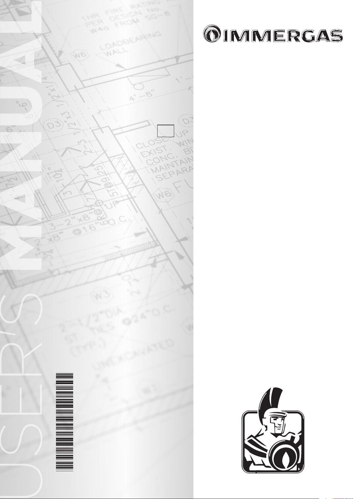
1.2 MAIN DIMENSIONS.
Key:
V - Electrical connection
AC - Domestic hot water outlet
AF - Domestic cold water inlet
RU - Return from boiler unit
MU - Flow to boiler unit
RP - Return to solar panels
MP - Flow from solar panels
RC - Domestic hot water recircula-
tion (Optional)
CONNECTIONS
SYSTEM
MU - RU MP - RP AF AC RC
3/4” 3/4” 3/4” 3/4” 1/2”
DOMESTIC HOT
WATER
1-1
MAINTENANCE TECHNICIAN
5
Page 6
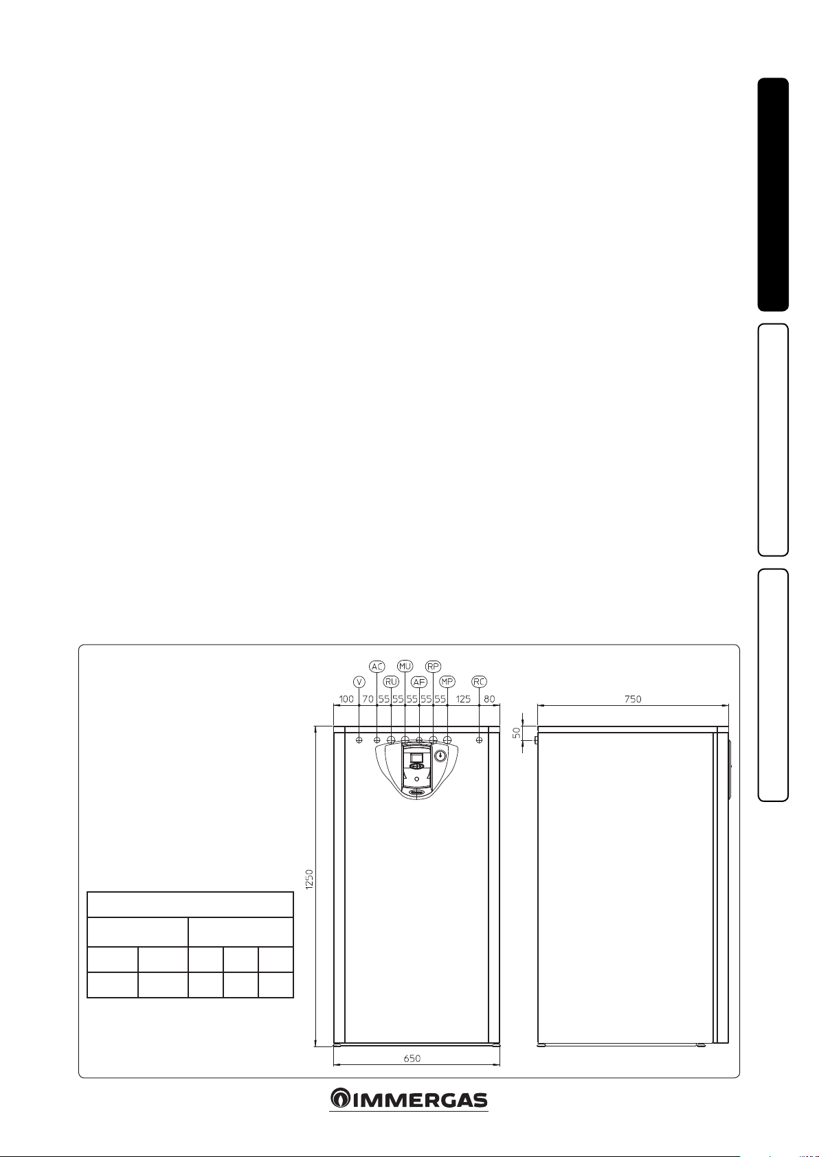
1.3 CONNECTION UNIT.
INSTALLERUSER
AC
1-2
Key:
V - Electrical connection
AC - 3/4” Domestic hot water outlet
MU
RU
RC
MP
AF
V
RP
RU - 3/4" return from storage tank
MU - 3/4" ow to storage tank
AF - 3/4” domestic cold water inlet
RP - 3/4” return to solar panels
MP - 3/4” ow from solar panels
RC - 1/2” recirculation (optional)
1.4 HYDRAULIC CONNECTION.
Before making the connections, all of the system
piping must be washed thoroughly to remove
any residues that could compromise the proper
operation of the storage tank. Water connections
must be made in a rational way using the couplings on the storage tank template. e storage
tank safety valve outlet must be connected to a
draining funnel. If this is not the case, the storage tank manufacturer declines any liability in
the event of ooding if the drain valve cuts in.
1.5 ELECTRICAL CONNECTION.
e storage tank has an IPX0D protection rating
for the entire appliance. Electrical safety of the
appliance is reached only when it is correctly connected to an ecient earthing system as specied
by current safety standards.
Attention: Immergas S.p.A. declines any responsibility for damage or physical injury caused by
failure to connect the storage tank to an ecient
earth system or failure to comply with the reference standards.
Also ensure that the electrical installation corresponds to maximum absorbed power specications as shown on the storage tank data-plate.
e storage tank unit is supplied complete with
an “X” type power cable without plug.
MAINTENANCE TECHNICIAN
Solar manifold probe connection.
Connect the solar manifold probe to pins 45
and 46 on the terminal board (Fig.1-12 part. 17)
present inside the storage tank unit, paying attention to eliminate the resistance R15 as indicated
in the wiring diagram.
Storage tank connection to the boiler.
Connect the storage tank to the boiler as indicated in the wiring diagram, using a cable (not
present) to connect clamps 36 and 37 to the boiler
and to the storage tank.
Storage tank unit electric connection.
e power supply cable must be connected to a
230V ±10% / 50Hz mains supply respecting L-N
polarity and earth connection;
must also have a multi-pole circuit breaker with
class III over-voltage category. When replacing
the power supply cable, contact a qualied rm
, this network
(e.g. the Authorised Aer-Sales Technical Assistance Service).
For the main power supply to the appliance,
never use adapters, multiple sockets or extension leads.
Solar collector return probe connection (optional).
Connect the solar collector return probe to pins
8 and 7 on the terminal board present inside the
storage tank unit.
Attention: aer the connections have bee made,
the new system layout must be set on the solar
control unit as follows:
- press the “i” key for about 10 seconds;
- use the scrolling keys to nd parameter 27
(system conguration);
- press the “i” key for about 2 seconds.
- upon accessing parameter 27, you will nd that
conguration 1 is set; use the scrolling keys to
select conguration 2.
- press the “i” key to conrm the selected conguration.
1.6 FILLING THE SYSTEM.
Once the storage tank has been connected, ll
the system via the boiler lling valve. Filling is
performed at low speed to ensure release of air
bubbles in the water via the boiler and central
heating system vents.
Close the lling valve when the boiler manometer pointer indicates approx. 1.2 bar (see boiler
instruction book).
1.7 DOMESTIC HOT WATER STORAGE
TANK UNIT.
e storage tank unit must be connected to a
boiler. It contains large coiled stainless steel heat
exchanger pipes, which allow to notably reduce
hot water production times. is storage tank
unit, manufactured with stainless steel casing and
bottoms, guarantees long duration through time.
e assembly concepts and welding (T.I.G.) are
implemented to the minimum detail to ensure
maximum reliability.
e upper inspection ange ensures practical
control of the storage tank unit and the coil heat
exchanger pipe and easy internal cleaning.
e DHW couplings are positioned on the lid
of the ange (cold inlet and hot outlet). e
Magnesium Anode holder cap including the
same, supplied as per standard for the internal
protection of the storage tank from possible corrosion, is found on the side of the storage tank.
IMPORTANT NOTE: have the eciency of the
storage tank Magnesium Anode checked annually by a qualied rm. e storage tank unit is
prepared for introduction of the domestic hot
water pump tting.
1.8 DHW MIXING VALVE.
e thermostatic mixing valve mixes the cold
water with the hot water and via an internal wax
element, sensitive to the temperature, automatically controls the temperature of the mixed water
set by the user.
N.B.: for excellent management of the temperatures, the mixing valve must be set by the installer
at a safety temperature required by the user. e
outlet temperature of the domestic hot water
can also depend on the value set on the boiler,
however, the upper limit temperature value of
the domestic hot water is always determined by
the position of the mixing valve: knob position 1
= 42°C, 2 = 48°C, 3 = 54°C, 4 = 60°C (standard)
(the values indicated refer to a storage tank with
water at 70°C).
Any release of the three-way mixing valve. If
aer a long period of inactivity the three-way
mixing valve is blocked, it is necessary to act
manually on the knob positioned on the top of
the same in a way to release the shutter of the
valve itself.
6
Page 7

1
2
11
4
5
1.9 STORAGE TANK UNIT HYDRAULIC
CIRCUIT RESISTANCE.
In order to guarantee sucient DHW ow rate,
it is important to consider the resistance of the
storage tank hydraulic circuit to be coupled to the
boiler. (Fig. 1-3). In order to connect the storage
tank unit to Immergas boilers properly, refer to
the boiler instruction book.
1.10 MAIN SOLAR CIRCULATION UNIT
COMPONENTS.
e pump unit allows you to connect the storage
tank to the solar manifold, making the water circulate according to the request of the control unit.
INSTALLERUSER
Hydraulic circuit resistance.
Head (kPa)
13
2
1
10
11
4
8
12
1-3
A - Storage tank unit hydraulic
A
Head (m c.a.)
Flow rate (l/h)
circuit resistance.
1-4
MAINTENANCE TECHNICIAN
3
IN
OUT
7
II
II
Min.
6
12
9
Key:
6
5
4
3
2
1
14
1 - Solar pump
2 - Non return valve, thermometer
3 - Valve drain tting
4 - Flow meter
5 - 6 bar safety valve
6 - 3/4” connection for expansion ves-
8
and cock
sel
9
7
5
7 - Manometer
8 - Draining valve
9 - Filling valve
10 - Insulating casing
11 - Flow rate regulator
12 - Inlet
13 - Outlet
14 - Reference for ow rate
13
6
reading
7
Page 8

1.11 CIRCULATION PUMP SOLAR
HEATING SYSTEM.
e units are supplied with circulating pumps
tted with speed regulator.
ese settings are suitable for most systems.
In fact, the pump is equipped with electronic
control to set advanced functions. For proper operation one must select the most suitable type of
operation for the system and select a speed in the
available range, with a focus on energy savings.
Display of operation status. During normal
INSTALLERUSER
operation the status LED (2) is on green (ashing
(FL) when it is in stand-by), the four yellow LEDs
(3) indicate circulator absorption according to
the following table:
Circulating pump LED Absorption
G Y Y Y Y
FL O O O O
G Y Y Y Y
On On O O O
Circulator in
stand-by
0 ÷ 25 %
Selection of operating mode. To see the c urrent
operation mode it is sucient to press button
(1) once.
To change operation mode press the button
for between 2 to 10 seconds until the current
conguration ashing, each time the button is
pressed all possible functions are scrolled cyclically according to the table (Fig. 1-6). Aer a
few seconds without doing any operation the
circulator memorises the selected mode and goes
back to operation display.
- Constant curve: the pump operates with a
contant curve. e circulator working point
will move up or down according to the system's
demand.
- PWM Prole: do not use this operation mode.
Selection button lock. e button has a feature
that locks its operation to prevent accidental
modications, to lock the control panel it is
necessary to press button (1) longer than 10
seconds (during which the current conguration
ashes), the active lock is signalled by all LEDs of
the control panel ashing. To unlock the button
press again longer than 10 seconds.
Real time diagnostics: in the event of malfunction the LEDs provide information on the
circulator operation status, see table (Fig. 1-7):
1-5
G Y Y Y Y
On On On O O
G Y Y Y Y
On On On On O
G Y Y Y Y
On On On On On
MAINTENANCE TECHNICIAN
25 ÷ 50 %
50 ÷ 75 %
75 ÷ 100 %
Circulating pump LED
G Y Y Y Y
On On On O O
G Y Y Y Y
On On On On O
G Y Y Y Y
On On On On On
G Y Y Y Y
On On On O On
1-6
Description
Constant curve
speed 1
Constant curve
speed 2
Constant curve
speed 3
Constant curve
speed 4 (default)
Key:
1 - Function selection button
2 - Green (G) / red (R) LED
3 - 4 yellow LEDs (Y)
DO NOT USE
Circulating pump LED
R Y Y Y Y
On O On O O
R Y Y Y Y
On O On On O
R Y Y Y Y
On O On On On
R Y Y Y Y
On O On O On
Description
PWM Prole
speed 1
PWM Prole
speed 2
PWM Prole
speed 3
PWM Prole
speed 4
1-7
Circulating pump LED
(rst red LED)
R Y Y Y Y
On O O O On
R Y Y Y Y
On O O On O
R Y Y Y Y
On O On O O
Description Diagnostics Remedy
Circulator pump blocked
Abnormal situation (the circulator
continues operating).
low power supply voltage
Electrical fault
(Circulator pump blocked)
Wait for the circulator to make automatic
e circulator pump cannot restart
automatically due to an anomaly
Voltage o range Check power supply
e circulator is locked due to power
supply too low or serious malfunction
release attempts or manually release the motor sha acting on the screw in the centre of
the head.
If the anomaly persists replace the circulator.
Check the power supply, if the anomaly persists
replace the circulator
8
Page 9

Solar circulation unit available head.
V3
V1
Head (kPa)
V2
Key:
Vn = Available head
An = Circulating pump absorbed power
V4
A4
A3
A2
INSTALLERUSER
A1
Circulator pump absorbed power (W)
Flow rate (l/h)
1.12 COMMISSIONING.
Preliminary checks on the solar system
Before lling the hydraulic circuit and starting
the system, carry out the following checks:
- ensure that the declaration of conformity of
installation of the solar system is supplied with
the appliance;
- make sure the safety devices are included and
are operating properly, particularly:
- safety valve (6 bar)
- expansion vessel
- thermostatic mixing valve
- make sure there are no leaks in the hydraulic
circuit;
- make sure there is an air vent valve positioned
in the highest point of the circuit above the
manifold and that it is operational.
- check connection to a 230V-50Hz power
mains, correct L-N polarity and the earthing
connection;
- Check that all the requirements relating to
the boiler and the central heating circuit have
been complied with, as described in the relative
boiler instruction book.
If even only a single safety check oers a negative
result, do not commission the system.
Expansion vessel factory-set pressure of the
solar circuit hydraulic unit.
To compensate the high temperatures that can be
reached by the liquid in the circuit and therefore
its dilation, an expansion vessel has been tted on
the UB INOX SOLAR 200 ErP storage tank, with
sucient capacity to perform this task.
e expansion vessels are supplied factory-set at
2.5 bar. It is therefore necessary to charge them to
the pressure necessary for the circuit.
e expansion vessel must be charged to:
2 bar + 0.1 bar for every metre of the water
column.
“metre of the water column” means the vertical
distance that is present between the expansion
vessel and the solar manifold.
Example:
e circulation unit is found on the ground oor
and the solar manifold is found on the roof at a
hypothetical height of 6 m, the distance to be
calculated is:
6 m x 0.1 bar = 0.6 bar
therefore the expansion vessel must be charged
to:
2 + 0.6 = 2.6 bar
Hydraulic unit safety valve.
ere is a safety valve present on the hydraulic
unit that protects the system from an excessive
increase in pressure. is valve intervenes by
discharging the liquid contained in the circuit
when the pressure reaches 6 bar.
If the safety valve intervenes and therefore part of
the liquid contained in the circuit is lost, it must
be re-integrated.
1-8
1.13 FILLING THE SOLAR CIRCUIT
SYSTEM.
e system can only be lled when:
- the system is completely assembled;
- any operational residues have been eliminated
that may cause obstructions and deteriorate the
features of the glycol over time;
- any presence of water in the system has been
eliminated, which could otherwise cause damage to the system in winter;
- the absence of leaks has been veried by checks
using air;
- the storage tank unit has been lled;
- the expansion vessel has been charged accord-
ing to system requirements.
e system must be lled only using the glycol
supplied by Immergas via an automatic pump.
e system must be lled with vent valve closed.
Proceed as follows to ll the system:
1 connect the ow pipe of the automatic pump to
the tting of the lling valve (9 Fig. 1-4) located
under the pump and open the valve.
2 connect the return pipe of the automatic pump
to the tting of the draining valve (8 Fig. 1-4)
and open the draining valve.
3 e ow-rate regulator screw (11 Fig. 1-4) must
be orientated horizontally to ensure the closure
of the integrated ball valve. Open the ball valve
with thermometer (2 Fig. 1-4) above the pump.
4 Fill the lling pump tank with the amount of
glycol necessary plus a minimum amount to
be le on the bottom of the tank in order to
prevent air circulating inside the circuit.
5 e lling stage must have a minimum dura-
tion of 20 ÷ 25 minutes. is time is required
to completely remove all air from the circuit.
Every now and again open the ow rate regulator adjustment screw in order to eliminate air
from inside (vertical position).
MAINTENANCE TECHNICIAN
9
Page 10

6 Eliminate any air in the solar circuit preferably
using the so-called "pressure shot" method,
which consists in raising the lling pressure of
the circuit followed by a quick opening of the
return valve (8 Fig. 1-4). is method allows
air to be expelled from the circuit.
7 Close the lling cock and switch the lling
pump o, open the regulator screw of the ow
rate regulator (notch in vertical position).
8 Leave the circuit pressurised. Any pressure
drop indicates a leak in the system.
INSTALLERUSER
Description of display.
Symbol State Description
9 Set the functioning pressure in the circuit at
2.0 bar + 0.1 bar for every metre in the distance
between the solar collector and the expansion
vessel (practically, set the same pressure between expansion vessel and system).
10 Switch the solar pump on at a maximum speed
and make it run for at least 15 minutes.
11 Disconnect the lling pump and close the
ttings using the relevant screw caps.
12 Open the ball valve above the pump com-
pletely.
Flashing Solar pump functioning
On Boiler burner enabled
On Communication with boiler active
Flashing Anomaly present
On Solar collector temperature sucient for functioning
Do not ll the system in conditions with strong
insolation and with the manifolds at high
temperatures.
Make sure that all air bubbles have been completely eliminated.
1.14 SOLAR CONTROL UNIT USER
INSTRUCTIONS.
e solar control unit user information are described successively.
Sn
Description of the control panel.
Symbol Description
MAINTENANCE TECHNICIAN
• Programming the functions.
Access to the board parameters menu is given
through the buttons present on the control unit.
To access the parameters menu and modify a
value necessary:
- Press and hold the ( ) key for 10 seconds. (access to the menu)
- Scroll to the parameter to be modied by pressing the (
- Press the ( ) key and then ( ) to modify
the value of the parameter selected.
) and ( ) buttons.
Flashing Anti-freeze function active
On Digit to display the temperatures, parameters and values.
Probe active
On
On Indicates the presence of the storage tank
On Indicates the presence of solar panel/s
Control unit switch-on - switch-o/Return to previous menu
Access to the parameters/system info/value conrmation
- Select the value and press the ( ) key to conrm.
Otherwise, press ( ) to exit. In this case, the
value set will not be memorised, but the previous one will be kept.
- To exit the parameter menu, press the ( )
button once or wait 60 seconds without pressing any keys.
S1 - DHW inhibition probe (NTC)
S2 - Solar storage tank probe (NTC)
S3 - Solar collector probe (PT1000)
Parameter/next value selection
Parameter/previous value selection
10
Page 11

List and description of parameters available.
e board has 34 parameters.
e parameters that go from 1 to 11 is simple
information and cannot be modied.
N°
Parameter
1 Soware Version 1÷99 10
2 Current temperature S1: NTC sensor (°C) 0÷120 -3 Current temperature S2: NTC sensor (°C) 0÷120 -4 Current temperature S3: PT1000 sensor (°C) 0÷170 -5 Current temperature S4: PT1000 sensor (°C) 0÷170 --
6
7
8
9
10 Current modulating pump speed (Vel.1=40% ÷Vel.5=100%) 0÷100% -11 System functioning hours timer -- --
12
13
14
15 Tank set-point (solar pump switch-o temperature) 60÷80°C 70°C
16 Value of the Δ solar collector ow - tank temperature dierential for solar pump switch-on 3÷20°C * 5°C
17 Solar collector ow Maximum Temperature (°C) 90÷160°C 140°C
18 Tank Maximum Temperature (°C) 70÷95°C 80°C
19
20 Diverter functioning (0 = O, 1 = Auto, 2 = On) 0 ÷ 2 1
21
22 Value of the Δ collector ow - tank temperature dierential for solar pump switch-o 1÷10°C * 3°C
23
24 Solar Pump functioning (0=On/O, 1=Modulating, 2 = On, 3 = O ) 0÷3 0
25
26 Selected system layout - DO NOT MODIFY 1÷6 6
27 System conguration (the range of values varies on the basis of the system selected) 1÷4 1
28 Priority logic (1= S1 has priority over S2 / 2= S2 has priority over S1) 1÷2 2
29 ermostat insertion temperature (S1) 30÷90°C
30 ermostat disconnection temperature (S1) 30÷90°C 30°C
31 DHW set 20÷60°C 45°C
32 Priority integration (0=Function deactivated) 0÷10°C 5°C
33 Parallel integration (0=Function deactivated) 0÷20°C 10°C
34 Solar pump functioning (0 = O, 1 = Auto, 2 = On) 0 ÷2 1
Maximum temperature S1 (with period of 24 hours starting from their last switch-on of the
device from OFF mode): NTC sensor (°C)
Maximum temperature S2 (with period of 24 hours starting from their last switch-on of the
device from OFF mode): NTC sensor (°C)
Maximum temperature S3 (with period of 24 hours starting from their last switch-on of the
device from OFF mode): PT1000 sensor (°C)
Maximum temperature S4 (with period of 24 hours starting from their last switch-on of the
device from OFF mode): PT1000 sensor (°C)
Value of the Δow - return solar collector temperature dierential for solar pump switch/on
(in presence of return probe)
Value of the temperature dierential for the modulation of the solar pump (for speeds 1 and
2)
Value of the temperature dierential for the modulation of the solar pump (for speeds 3, 4
and 5)
Value of the temperature dierential between the solar collector maximum temperature
(PAR 17) and the solar collector temperature, above which the solar collector cooling function activates (Solar collector cooling function) (0=Function deactivated)
Value of the Δ ow - return temperature dierential below which the collector is recognised
as cold (Cold solar collector recognition func.)
Solar collector anti-freeze temperature value (see Solar collector anti-freeze func.)
(0=Function deactivated, 1÷10°C=Protection temperature)
Appliance conguration
(stand alone=1, PLB-BUS=2, PLB-BUS remote control only=3)
Description of the Parameter Values Field Default
0÷120 --
0÷120 --
0÷170 --
0÷170 --
5÷30°C 10°C
5÷20°C 10°C
2÷10°C 5°C
0÷20°C 0
0÷10°C 5°C
0÷10°C 0
1÷3 1
30°C
INSTALLERUSER
MAINTENANCE TECHNICIAN
*=the range of parameters 16 and 22 is dynamic, it is not allowed to set a ∆ between these two parameters lower than 2.
11
Page 12

• Use and operation.
- Start-up display.
Every time power is supplied to the appliance,
the display will activate all symbols for 2 seconds:
INSTALLERUSER
while in the next 5 seconds, the display will
indicate the board soware version:
Aer which, the following information regard-
ing the type of system will be displayed, the
temperature of the solar collector (1 ÷ 170°C
upper digit) and the temperature of the storage
tank probe (1 ÷ 125°C lower digit):
MAINTENANCE TECHNICIAN
Functioning.
•
For the description of the parameters, refer to
the table in the previous paragraph
- OFF mode. By pressing the ( ) key for 3
seconds, the appliance switches to o mode
(also in the event of anomalies). In this way,
it is not operational and the display shows
o. Only the anti-freeze protection and the
pump anti-block remain active.
1-9
1-10
1-11
- Solar pump functioning.
e pump activates and deactivates automati-
cally when it is set in On/O mode.
Activation: the solar pump will be activated
by the board if the following conditions occur
at the same time:
T tank < PAR15 – PAR16
and
Solar collector T - tank T > PAR16
Disabling: the board disables the solar pump
if one of the following conditions occurs:
Tank T > PAR 15
or
Solar collector T< tank T + PAR 22
Manual mode: the pump can be set in On
mode (always on) or O mode (always o).
In the event of manual setting, the protection
functions are inhibited.
- Solar manifold cooling function. is func-
tion is used to manage the pump in the event
of overheating of the solar panel according to
the following table:
Description Condition
Solar pump
activation
Solar pump
deactivation
PAR 15 < tank T < PAR 18
Solar collector T > PAR 17 - PAR 19
Solar collector T (PAR 17 - PAR
Solar collector T > PAR 17
(reactivates with solar collector T <
+
19) -1°C
or
Tank T ≥ PAR 18 +1°C
or
PAR17 -1°C)
With parameter 19=0, the solar collector
cooling function is deactivated; the following
conditions remain active:
Solar collector T > PAR17 => Solar pump o
Solar collector T < PAR17– 1°C => Solar
pump on
- Cold solar manifold recognition function.
e board will disable the solar pump (pre-
sent only with return probe) when:
Solar collector T– solar collector return T <
PAR 21
- Solar manifold anti-freeze function. e
Solar Pump activates when:
Solar collector T < PAR 23
e board will not deactivate the solar pump
until:
Solar collector T > PAR 23 + 1°C
Attention: the default anti-f reeze function is
disabled PAR 23=0
- Solar pump anti-block function. Aer 24
hours of inactivity, the system pumps are
activated for 3 seconds.
- Diverter valve anti-block function. Aer
24 hours of inactivity, the diverter valve will
be activated for 5 seconds (in systems tted
with the diverter valve).
- Priority solar function. e function is ac-
tive when:
DHW inhibition probe T (PAR 31 - PAR 33)
< DHW set (parallel integration)
DHW inhibition probe T (PAR 31 - PAR 33)
< DHW set (priority integration) and solar
loading pump in o for a time > 5 minutes
• Anomalies.
e following table describes the possible anomalous conditions that will be displayed on the basis
of the system ration selected.
e possible functioning error conditions are
displayed on the user interface display.
If an anomaly should occur, the (
) symbol
starts to ash as well as the back light (anomaly).
If a no communication anomaly should occur,
the (
) + ( ) symbols start to ash as
well as the back light (communication anomaly).
Description of anomaly Fault code
S1 NTC sensor fault 81
S2 NTC sensor fault 82
S3 T1000 sensor fault 83
Solar pump o 87
- Anomaly 81 NTC Sensor faulty: the sensor
fault, i.e. a short circuit or open circuit, disables
the Solar Pump (active system protection). e
protection is deactivated immediately when
this fault is resolved.
- Anomaly 82 NTC Sensor faulty: the sensor
fault, i.e. a short circuit or open circuit, disables
the Solar Pump (active system protection). e
protection is deactivated immediately when
this fault is resolved.
- Anomaly 83 PT1000 Sensor faulty: the sensor
fault, i.e. a short circuit or open circuit, disables
the Solar Pump (active system protection). e
protection is deactivated immediately when
this fault is resolved.
- Solar pump O: the solar control unit indicates
that the solar pump is in forced Off mode
(parameter 24).
• Technic al data.
Power Supply: ...................230 Vac + 10% ÷ 15%
Frequency:
Mains (PF1):
Free contact outputs:
...........................................50 Hz ±5%
.......................3.15 AF (rapid) 5x20
.................5A 30 Vdc relay,
10 A 250 Vdc
(Maximum charge allowed: 0.25 A 230 Vac)
12
Page 13

1.15 MAIN COMPONENTS.
INSTALLERUSER
Key:
1 - Domestic hot water circuit mixing valve
2 - Stainless steel coil for storage tank
3 - Domestic hot water probe
4 - D.H.W. expansion vessel
5 - Magnesium anode
6 - Domestic hot water unabling probe
7 - 8 bar safety valve
8 - Storage tank unit draining valve
9 - Shut-o valve with thermometer
10 - 6 bar safety valve
11 - Solar pump
1.16 KITS AVAILABLE ON REQUEST.
• Recirculation kit (on request). e storage tank
unit is prepared for application of the pump
kit. Immergas supplies a series of ttings and
attachments that allow connection between
the storage tank unit and domestic hot water
system. e pump kit attachment is also envisioned on the template.
• Electronic anode kit (on request). Direct current is made to circulate between the device and
the tank to be protected via a special titanium
anode. Use the free tting on the storage tank
supper ange for installation of the anode.
e above-mentioned kits are supplied complete
with instructions for assembly and use.
12 - ermometer probe
13 - Flow meter
14 - Solar expansion vessel
15 - Stainless steel coil that can be coupled to solar panels
16 - Solar panel probe
17 - Storage tank electric connections terminal board
1- 12
MAINTENANCE TECHNICIAN
13
Page 14

USE AND MAINTENANCE
2
INSTRUCTIONS
2.1 CLEANING AND MAINTENANCE.
Attention: to preserve integrity of the storage
tank unit and keep the safety features, performance and reliability, which distinguish it,
unchanged over time, you must at least execute
maintenance operations on a yearly basis in
compliance with what is stated in the relative
point at “annual check and maintenance of the
appliance”, in compliance with national, regional,
INSTALLERUSER
or local standards in force. Annual maintenance
is essential to validate the Immergas warranty.
We recommend stipulating a yearly cleaning
and maintenance contract with an authorised
local rm.
2.2 EMPTYING THE STORAGE TANK
UNIT.
To drain the storage tank, use the special draining valve in the lower part of the storage tank
(Fig. 1-12 part. 8).
Before draining, ensure that the DHW inlet
valve is closed.
2.3 CLEANING THE CASE.
Use damp cloths and neutral detergent to clean
the storage tank casing. Never use abrasive or
powder detergents.
2.4 DECOMMISSIONING.
In the event of decommissioning the storage
tank, contact an authorised company for the
relative operations, among other things making
sure that water supply is disconnected.
At the end of its service life the appliance must
not be disposed of like normal household waste
nor abandoned in the environment, but must
be removed by a professionally authorised
company. Contact the manufacturer for disposal
instructions.
2.5 CONTROL PANEL.
MAINTENANCE TECHNICIAN
Key:
1 - Solar control unit
2 - Solar manometer
2-1
14
Page 15

CHECKS
3
AND MAINTENANCE
3.1 HYDRAULIC DIAGRAM.
INSTALLERUSER
Key:
1 - Storage tank unit draining valve
2 - 8 bar safety valve
3 - Magnesium anode
4 - D.H.W. expansion vessel
5 - Stainless steel coil for storage tank
6 - System draining valve
7 - Domestic hot water circuit mixing valve
8 - Mixing valve lter
9 - One-way valve (OV 20)
10 - Cold water inlet lter
11 - One-way valve (OV 15) (Optional)
12 - Cold water inlet cock
13 - One-way solar valve
14 - 6 bar safety valve
15 - Shut-o valve with thermometer
MAINTENANCE TECHNICIAN
16 - Solar expansion vessel
17 - Solar pump
18 - Flow meter
19 - Domestic hot water probe
20 - Domestic hot water unabling probe
21 - Stainless steel coil that can be coupled to solar panels
22 - Solar system draining valve
23 - Solar panel probe
AC - Domestic hot water outlet
RC - Recirculation (Optional)
AF - Domestic cold water inlet
MU - Flow to boiler unit
RU - Return from storage tank unit
MP - Flow from solar panels
RP - Return to solar panels
3-1
15
Page 16

3.2 WIRING DIAGRAM.
INSTALLERUSER
8
9
8
9
12
12
6
6
5
5
4
4
11
9
11
8
Key:
A12 - Solar management control unit
B2 - Domestic hot water probe (NTC)
B11 - Solar manifold probe (PT1000)
B12 - Solar storage tank probe (NTC)
B19 - DHW inhibition probe (NTC)
B20 - Solar manifold return probe (PT1000) (Optional)
M6 - Solar circuit circulator
R8 - Storage tank function unabling resistance
R15 - Solar manifold probe unabling resistance
9
8
13
13
13
14
4
1
4
4
5
5
6
7
10
8
9
2
3
1 - Supply voltage 230 Vac 50 Hz
2 - Boiler clamps 36 and 37
3 - Domestic hot water integration
4 - Black
5 - White
6 - Green
7 - Orange
8 - Blue
9 - Brown
10 - Purple
11 - Red
12 - Yellow
13 - Yellow/green
14 - Grey
3-2
e solar collector probe (B11) must be connected to clamps 45 and 46 eliminating the
resistance R15.
3.3 YEARLY APPLIANCE CHECK AND
MAINTENANCE.
e following checks and maintenance should
be performed at least once a year.
MAINTENANCE TECHNICIAN
- Check for water leaks or oxidation from/on the
ttings;
- Check that the safety and control devices have
not been tampered with and in particular, the
DHW regulation NTC probe;
- Check the integrity of the storage tank Magnesium anode;
- Check the state of the internal coil;
- Check for any slurry deposits on the bottom of
the storage tank.
16
Page 17

3.4 REMOVING THE CASING.
To facilitate storage tank maintenance, the casing
can be completely removed as follows:
IMPORTANT NOTE: the procedure for removing the casing is the same for all storage tank
unit models.
- remove the lid (1) by pulling it upwards;
- undo the screws (2) and pull the front panel
outwards (3);
- undo the screws (4) of the sides (5) on the top
and in the lower part of the sides themselves.
Aer having released them from the screws,
they can be removed by pulling them forward
and then upwards.
3.5 REPLACING THE ANODE.
e magnesium anode must be replaced annually
(Fig. 1-12 part. 5), present in the storage tank,
must be replaced every year with another having
the same features.
INSTALLERUSER
1
4
5
4
2
222
MAINTENANCE TECHNICIAN
3
17
4
5
3-3
Page 18

3.6 TECHNICAL SPECIFICATIONS.
Storage tank useful capacity l 200
Domestic hot water side maximum pressure bar 8
DHW side maximum temperature °C 99
Domestic hot water expansion vessel total volume l 4.3
Dispersions kW/24h 3.42
Psbsol W/K 3.17
Coil thickness mm 0.8
Solar coil length mm 6500
CH coil length mm 10700
INSTALLERUSER
Solar coil exchange surface m
CH coil exchange surface m
2
2
Solar coil capacity l 1.73
CH coil capacity l 2.84
CH/solar primary uid ow rate (coil) l/h 1140 / 1140
Coil head loss at 1000 l/h kPa (m H
O) 12.3 (1.25)
2
Central heating side maximum pressure bar 6
Central heating side maximum temperature °C 90
Solar heat exchange maximum output kW 23.8
CH heat exchange maximum output kW 26.5
Full weight kg 310.67
Empty weight kg 106.1
Total water content l 204.57
Solar circuit maximum pressure bar 6
Total volume solar expansion vessel l 18
Solar expansion vessel pre-charge bar 2.5
Content of glycoled water in the solar circuit l 3.7
Power absorbed by the solar pump W 36
EEI - ≤ 0,20 - Part. 3
Equipment electrical system protection - IPX0D
Max. solar pump head m c.a. 6
Solar circuit maximum peak temperature °C 150
Solar circuit maximum continuous working temperature °C 130
0.41
0.67
MAINTENANCE TECHNICIAN
18
Page 19

3.7 PRODUCT SHEET IN COMPLIANCE WITH REGULATION 812/2013.
UB INOX SOLAR 200 ERP
A
B
C
D
E
F
G
F
143 W
200 L
19
Page 20

Follow us
Immergas Italia
immergas.com
Immergas S.p.A.
42041 Brescello (RE) - Italy
Tel. 0522.689011
Fax 0522.680617
Certified company ISO 9001
ИЗКЛЮЧИТЕЛЕН ПРЕДСТАВИТЕЛ И СЕРВИЗ
АМАКС ГАЗ ООД
is instruction booklet is made of ecological paper Cod. 1.038280ENG - rev. ST.001960/000 - 07/15 - Inglese per IRLANDA (IE)
1261 Мрамор, София ул В. Левски 148
Tel. 0700 112 66
Fax 02 902 46 70
www.amaxgas.com
 Loading...