

Page 1
UB INOX
Solar 200-2
STORAGE
TANK UNIT
Instruction booklet and
warning
IE
*1.033447ENG*
Page 2
Dear Client,
Our compliments for having chosen a top-quality Immergas product, able to assure well-being and safety for a long period of time. As an Immergas customer
you can also count on a qualied aer-sales service, prepared and updated to guarantee constant eciency of your storage tank unit.
Read the following pages carefully: you will be able to draw useful suggestions regarding the correct use of the appliance, the respect of which, will conrm
your satisfaction for the Immergas product.
For any interventions or routine maintenance contact Immergas Authorised Centres: these have original spare parts and boast of specic preparation directly
from the manufacturer.
General recommendations
e instruction book is an integral and essential part of the product and must be consigned to the user.
It must be kept well and consulted carefully, as all of the warnings supply important indications for safety in the installation, use and maintenance stages.
Installation and maintenance must be performed in compliance with the regulations in force, according to the manufacturer and by professionally
qualied sta, intending sta with specic technical skills in the plant sector, as envisioned by the Law in force.
Incorrect installation can cause injury to persons and animals and damage to objects, for which the manufacturer is not liable. Maintenance must be carried
out by skilled technical sta. e Immergas Authorised Aer-sales Service represents a guarantee of qualications and professionalism.
e appliance must only be destined for the use for which it has been expressly declared. Any other use must be considered improper and therefore dangerous.
If errors occur during installation, running and maintenance, due to the non-compliance of technical laws in force, standards or instructions contained in
this book (or however supplied by the manufacturer), the manufacturer is excluded from any contractual and extra-contractual liability for any damage
and the appliance warranty is invalidated.
For further information regarding legislative and statutory provisions relative to the installation, consult the Immergas site at the following address: www.
immergas.com.
DECLARATION OF CONFORMITY
For the purpose and eect of the 97/23/CE PED Directive, 2004/108/CE EMC Directive and 2006/95/CE Low Voltage Directive.
e Manufacturer: Immergas S.p.A. v. Cisa Ligure n° 95 42041 Brescello (RE)
DECLARES THAT: the Immergas storage tanks model:
UB INOX Solar 200-2
are in compliance with the same European Community Directives.
Mauro Guareschi
Research & Development Director
Signature:
INDEX
Immergas S.p.A. declines all liability due to printing or transcription errors, reserving the right to make any modications to its technical and commercial
documents without forewarning.
1 Storage tank unit installation ................... 4
1.1 Installation recommendations. ................4
1.2 Main dimensions. ...................................... 4
1.3 Connection group. ....................................4
1.4 Electrical connection: ............................... 5
1.5 System lling. ............................................. 5
1.6 Domestic hot water storage tank unit. ... 5
1.7 Hydraulic circuit resistance. ....................5
1.8 Circulation pump. .....................................5
1.9 DHW mixing valve. .................................. 6
1.10 Kits available on request. .......................... 6
1.11 Main components. .................................... 6
1.12 Circulation unit main components. ....... 7
1.13 Commissioning. ........................................ 7
1.14 Solar circuit system lling. .......................7
1.15 Solar control unit user instructions. .......8
2 Instructions for use and maintenance. 11
2.1 Cleaning and maintenance. ................... 11
2.2 Emptying the storage tank unit. ............ 11
2.3 Case cleaning. .......................................... 11
2.4 Decommissioning. .................................. 11
2.5 Control panel. ..........................................11
3 Control and maintenance .....................12
3.1 Hydraulic diagram. .................................12
3.2 Wiring diagram. ......................................13
3.3 Yearly appliance check
and maintenance. ....................................13
3.4 Casing removal. .......................................14
3.5 Replacing the anode. ............................... 14
3.6 Technical data. .........................................14
USER pageINSTALLER page MAINTENANCE TECHNICIAN page
Page 3
3
1-1
1-2
V
RU
MU
RP
MP
RC
AF
AC
INSTALLERUSER
MAINTENANCE TECHNICIAN
1
STORAGE TANK UNIT
INSTALLATION
1.1 INSTALLATION
RECOMMENDATIONS.
Only professionally enabled heating/plumbing
technicians are authorised to install Immergas
appliances.
Installation must be carried out according to the
Standards, current legislation and in compliance
with local technical regulations and the required
technical procedures.
Before installing the appliance, ensure that it is
delivered in perfect condition; if in doubt, contact
the supplier immediately. Packing materials
(staples, nails, plastic bags, polystyrene foam,
etc.) constitute a hazard and must be kept out of
the reach of children.
If the appliance is installed inside or between
cabinets, ensure sufficient space for normal
servicing; therefore it is advisable to leave a gap
of 2÷3 cm between the storage tank casing and
the sides of the cabinet.
In the event of malfunctions, faults or incorrect
operation, turn the appliance o immediately
and contact a qualif ied technician (e.g. the
Immergas Technical Aer-Sales Centre, which
has specically trained sta and original spare
parts). Do not attempt to modify or repair the
appliance alone.
Failure to comply with the above implies personal
liability and invalidates the warranty.
• Installation Standards: These storage tanks
have been designed for oor installation; they
must be used for the storage of domestic hot
water and similar purposes. ey have not be
designed for wall-installation.
Important: these units are used to store water at
a temperature below boiling point at atmospheric
pressure. ey must be connected to a boiler and
to a DHW water distribution network. ey must
be installed in rooms where the temperature
cannot fall below 0°C and must not be exposed
to atmospheric agents.
Key:
V - Electrical connection
AC - DHW outlet
RU - Return from storage tank unit
MU - Flow to storage tank unit
AF - DHW inlet
RP - Return to solar panels
MP - Flow from solar panels
RC - DHW recirculation pump (Optional)
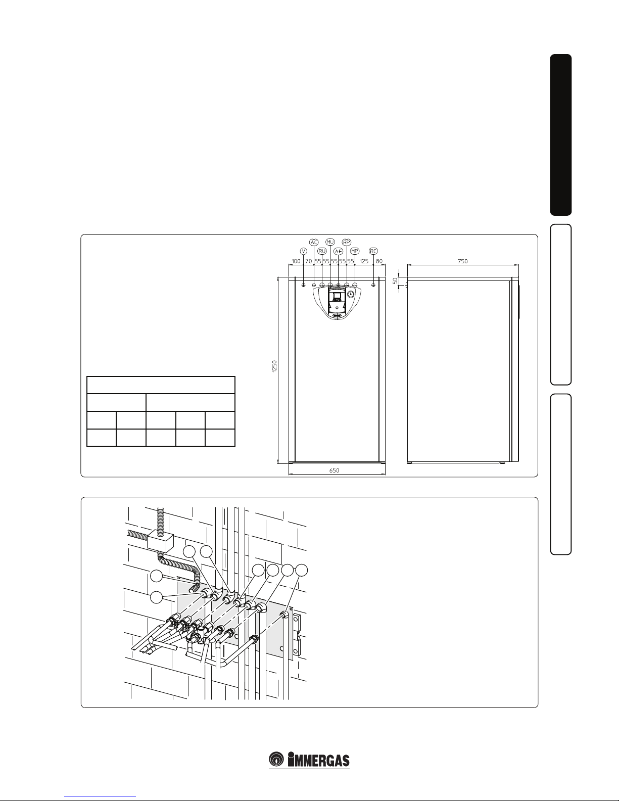
1.2 MAIN DIMENSIONS.
Hydr aulic connection. Before maki ng the
connections, all of the system piping must be
washed thoroughly to remove any residues that
could compromise the good functioning of the
1.3 CONNECTION GROUP.
Key:
V - Electrical connection
AC - 3/4'' DHW outlet
RU - 3/4" return from storage tank unit
MU - 3/4" ow to storage tank unit
AF - 3/4'' DHW inlet
RP - 3/4" return to solar panels
MP - 3/4” ow from solar panels
RC - 1/2” DHW recirculation pump (Optional)
storage tank. Water connections must be made in
a rational way using the couplings on the storage
tank template. e storage tank safety valve outlet
must be connected to a draining funnel. If this
is not the case, the storage tank manufacturer
declines any liability in the event of ooding if
the drain valve cuts in.
CONNECTIONS
SYSTEM DOMESTIC HOT WATER
MU-RU MP-RP AF AC RC
3/4” 3/4” 3/4” 3/4” 1/2”
Page 4
4
1-3
1-4
B
A
A
INSTALLERUSER
MAINTENANCE TECHNICIAN
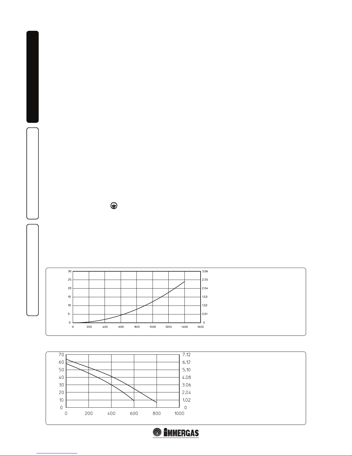
Hydraulic circuit resistance.
Head (kPa)
Flow rate (l/h)
Head (m H
2
O)
A - Storage tank unit hydraulic
circuit resistance
1.4 ELECTRICAL CONNECTION:
e storage tank has an IPX0D protection rating
for the entire appliance. Electrical safety of the
appliance is reached only when it is correctly
connected to an efficient earthing system as
specied by current safety standards.
Imp ortant: Imm ergas S.p. A. dec lines any
responsibility for damage or physical injury
caused by failure to connect the storage tank unit
to an ecient earth system or failure to comply
with the reference standards.
Als o ensure that the elec tr ic al inst al lation
corresponds to maximum absorbed power
specifications as shown on the storage tank
data-plate.
e storage tank unit is supplied complete with
an “X” type power cable without plug.
Solar collector probe connection.
Connect the solar collector probe to pins 45
and 46 onto the terminal board (Fig.1-5 part.
17) present inside the storage tank unit, paying
attention to eliminate the resistance R15 as
indicated in the wiring diagram.
Storage tank connection to the boiler.
Connec t th e storage tank to the boi le r as
indicated in the wiring diagram, using a cable
(not present) to connect clamps 36 and 37 to the
boiler and to the storage tank.
Storage tank unit electric connection.
e power supply cable must be connected to
a 230V ±10% / 50Hz mains supply respecting
L-N polarity and earth connection
. is
network must also have an omnipolar circuit
breaker with class III over-voltage category.
When replacing the power supply cable, contact
a qualied technician (e.g. the Immergas AerSales Technical Assistance Service).
For the main power supply to the appliance,
never use adapters, multiple sockets or extension
leads.
Sola r colle ctor retur n pr ob e conn ectio n
(optional).
Connect the solar collector return probe to pins
8 and 7 on the terminal board present inside the
storage tank unit.
Important: aer the connections have bee made,
the new system layout must be set on the solar
control unit as follows:
- press the “i” key for about 10 seconds;
- use the scrolling keys to nd parameter 27
(system conguration);
- press the “i” key for about 2 seconds.
- on enter i n g pa r ameter 2 7, fi nd t hat
conguration 1 is set; use the scrolling keys to
select conguration 2.
- press the “i” key to conrm the conguration
selected.
1.5 SYSTEM FILLING.
Once the storage tank has been connected, ll
the system via the boiler lling valve. Filling is
performed at low speed to ensure release of air
bubbles in the water via the boiler and central
heating system vents.
Close the lling valve when the boiler manometer
pointer indicates approx. 1.2 bar (see boiler
instruction book).
1.6 DOMESTIC HOT WATER STORAGE
TANK UNIT.
e storage tank unit must be connected to a
boiler. It contains large coiled stainless steel heat
exchanger pipes, which allow to notably reduce
hot water production times. is storage tank
unit, manufactured with stainless steel casing and
bottoms, guarantees long duration through time.
e assembly concepts and welding (T.I.G.) are
implemented to the minimum detail to ensure
maximum reliability.
e upper inspection ange ensures practical
control of the storage tank unit and the coil heat
exchanger pipe and easy internal cleaning.
e DHW couplings are positioned on the lid
of the ange (cold inlet and hot outlet). e
Magnesium Anode holder cap including the
same, supplied as per standard for the internal
protection of the storage tank from possible
corrosion, is found on the side of the storage tank.
N.B.: every yea r a skilled technician (e.g.
Immerg as Authorised After-sales Ser vice) ,
must check the eciency of the storage tank
unit Magnesium Anode. e storage tank unit
is prepared for introduction of the domestic hot
water pump tting.
1.7 HYDRAULIC CIRCUIT RESISTANCE.
In order to guarantee sucient DHW ow rate,
it is important to consider the resistance of the
storage tank hydraulic circuit to be coupled to
the boiler. (Fig. 1-3). For correct connection of
the storage tank unit to Immergas boilers, see the
boiler instruction book.
1.8 CIRCULATION PUMP.
e storage tank unit is supplied with a built-in
circulation pump with 3-position electric speed
control. With the circulation pump on first
speed it is probable that there is not sucient
circulation. e circulation pump is already tted
with a capacitor.
Pump release. If, aer a prolonged period of
inactivity, the circulation pump is blocked,
unscrew the front cap and turn the motor sha
using a screwdriver. During this operation, avoid
damage to the motor.
Circulation group available head.
Head (m H
2
O)
Head (kPa)
Flow rate (l/h)
A = Head available to the pump unit at third speed
B = Head available to the pump unit at second speed
Page 5
5
1-4
1- 5
INSTALLERUSER
MAINTENANCE TECHNICIAN
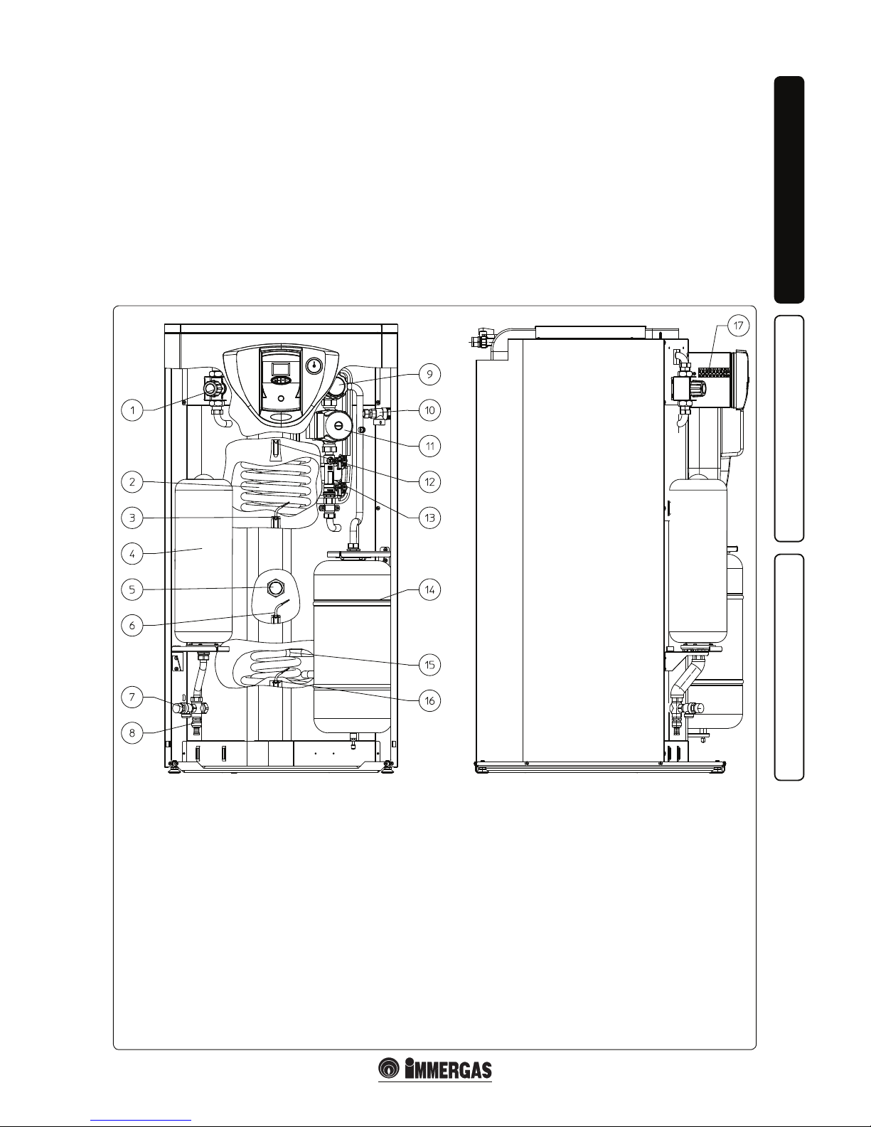
Key:
1 - DHW circuit mixing valve.
2 - Stainless steel coil for storage tank
3 - Domestic hot water probe
4 - DHW expansion vessel
5 - Magnesium anode
6 - DHW inlet probe
7 - 8 bar safety valve
8 - Storage tank draining valve
9 - Shut-o valve with thermometer
10 - 6 bar safety valve
11 - Solar pump
12 - ermometer probe
13 - Flow meter
14 - Solar expansion vessel
15 - Stainless steel coil that can be coupled to solar panels
16 - Solar panels probe
17 - Storage tank unit electric connections terminal board
1.11 MAIN COMPONENTS.
1.9 DHW MIXING VALVE.
e thermostatic mixing valve mixes the cold
water with the hot water and via an internal
wax element, sensit ive to the temperature,
automatically controls the temperature of the
mixed water set by the user.
N. B.: for exce llent mana geme nt of the
temperatures, the mixing valve must be set by
the installer at a safety temperature required by
the user. e DHW output temperature can also
depend on the value set on the boiler, however,
the DHW temperature upper limit value is always
determined by the position of the mixing valve:
knob position 1 = 42°C, 2 = 48°C, 3 = 54°C, 4 =
60°C (as per standard) (the values indicated refer
to a storage tank with water at 70°C).
Any release of the three-way mixing valve. If
aer a long period of inactivity the three-way
mixing valve is blocked, it is necessary to act
manually on the knob positioned on the top of
the same in a way to release the shutter of the
valve itself.
1.10 KITS AVAILABLE ON REQUEST.
• Pump kit (on request). e storage tank unit
is prepared for application of the pump kit.
Immergas supplies a series of fittings and
attachments that allow connection between
the storage tank unit and domestic hot water
system. The pump kit attachment is also
envisioned on the template.
• Ele ct ronic anode kit (on request). Direct
current is made to circulate between the device
and the tank to be protected via a special
titanium anode. Use the free tting on the
storage tank supper ange for installation of
the anode.
e above-mentioned kits are supplied complete
with instructions for assembly and use.
Page 6

6
1
2
3
4
5
6
7
6
10
11
1
4
8
12
9
14
2
13
3
5
1
IN
OUT
2
9
8
11
4
5
7
12
6
13
1- 6
INSTALLERUSER
MAINTENANCE TECHNICIAN
Key:
1 - Solar pump
2 - Shut-o valve with thermometer
3 - Safety valve drain tting
4 - Flow meter
5 - 6 bar safety valve
6 - 3/4” connection for expansion vessel
7 - Manometer
8 - Draining valve
9 - Filling valve
10 - Insulating casing
11 - Flow rate regulator
12 - Inlet
13 - Output
14 - Reference for ow rate reading
1.12 CIRCULATION UNIT MAIN
COMPONENTS.
e pump unit allows to connect the storage tank
to the solar collector, making the water circulate
according to the requests of the control unit.
1.13 COMMISSIONING.
Preliminary checks on the solar system
Before lling the hydraulic circuit and starting
the system, carry out the following checks:
- ensure that the declaration of conformity of
installation of the solar system is supplied with
the appliance;
- check the presence of the safety devices and
their functionality, particularly:
- safety valve (6 bar)
- expansion vessel
- thermostatic mixing valve
- check that there are no leaks in the hydraulic
circuit;
- check that there is an air vent valve positioned
in the highest point of the circuit above the
collector and that it is operational;
- check connection to a 230V-50Hz power
mains, correct L-N polarity and the earthing
connection;
- check that all prescriptions relative to the
boiler and the CH circuit have been respected,
as described in the relative boiler instruction
book.
If even only one control inherent to safety gives a
negative result, do not start the system.
Expansion vessel factory-set pressure of the
solar circuit hydraulic unit.
To compensate the high temperatures that can be
reached by the liquid in the circuit and therefore
its dil at ion, an expansion vessel has been
envisioned on the UB INOX Solar 200-2 storage
tank, with sucient capacity to perform this task.
e expansion vessels are supplied factory-set at
2.5 bar. It is therefore necessary to charge them to
the pressure necessary for the circuit.
e expansion vessel must be charged to:
2 bar + 0.1 bar for every metre of the water
column.
“metre of the water column” means the vertical
distance that is present between the expansion
vessel and the solar collector.
Example:
e circulation unit is found on the ground oor
and the solar collector is found on the roof at a
hypothetical height of 6 m, the distance to be
calculated is:
6 m x 0.1 bar = 0.6 bar
therefore the expansion vessel must be charged
to:
2 + 0.6 = 2.6 bar
Hydraulic unit safety valve.
ere is a safety valve present on the hydraulic
unit that protects the system from an excessive
increase in pressure. is valve intervenes by
discharging the liquid contained in the circuit
when the pressure reaches 6 bar.
If the safety valve intervenes and therefore part
of the liquid contained in the circuit is lost, this
must be re-integrated.
1.14 SOLAR CIRCUIT SYSTEM FILLING.
e system can only be lled when:
- the system is assembled completely;
- any working residues have been eliminated
that cause obstruc tions and through time
deteriorate the features of the glycol;
- all presence of water in the system has been
eliminated, which could cause damage to the
system in winter;
- the absence of leaks has been veried by checks
using air;
- the storage tank unit has been lled;
- the exp ans ion vess el ha s be en charge d
according to system requirements.
e system must be lled only using the glycol
supplied by Immergas via an automatic pump.
e system must be lled with vent valve closed.
Proceed as follows to ll the system:
1 connect the automatic pump ow pipe to the
lling valve tting (9 Fig. 1-6) positioned below
the pump and open the valve itself.
2 connect the automatic pump return pipe to the
draining valve tting (8 Fig. 1-6) and open the
draining valve.
3 The flow rate regu lator adjustment screw
(11 Fig. 1-6) must be horizontal in order to
guarantee closure of the integrated ball valve.
Open the ball valve with thermometer (2 Fig.
1-6) positioned over the pump.
4 ll the lling pump tank with the amount of
glycol necessary plus a minimum stock to
be le on the bottom of the tank in order to
prevent air circulating inside the circuit.
5 Th e fi lli ng pha se mu st ha ve m ini mum
duration of 20 ÷ 25 minutes. is is the time
needed to completely remove all air from the
circuit. Every now and again open the ow
rate regulator adjustment screw in order to
eliminate air from inside (vertical position).
6 Eliminate any air in the solar circuit preferably
using the so-called "pressure shot" method,
which consists in raising the lling pressure of
the circuit followed by a quick opening of the
return valve (8 Fig. 1-6). is method allows
to expel the air from the circuit.
Page 7

7
INSTALLERUSER
MAINTENANCE TECHNICIAN
7 Close the lling valve and switch the lling
pump o, open the adjustment screw of the
ow rate regulator (notch in vertical position).
8 Leave the circuit pressurised. Any pressure
drop indicates a leak in the system.
9 Set the functioning pressure in the circuit at
2 bar + 0.1 bar for every metre in the distance
between the solar collector and the expansion
vessel (pr ac ti cally, set the same pressure
between expansion vessel and system).
Description of display.
Symbol State Description
Flashing Solar pump functioning
On Boiler burner enabled
On Communication with boiler active
Flashing Anomaly presence
On Solar collector temperature sucient for functioning
Flashing Anti-freeze function active
On Digit to display the temperatures, parameters and values.
Sn
On
Probe active
S1 - DHW inhibition probe (NTC)
S2 - Solar storage tank probe (NTC)
S3 - Solar collector probe (PT1000)
On Indicates the presence of the storage tank
On Indicates the presence of solar panel/s
Description of the control panel.
Symbol Description
Control unit switch-on - switch-o/Return to previous menu
Parameter/next value selection
Parameter/previous value selection
Access to the parameters/system info/value conrmation
• Functions programming.
Access to the board parameters menu is given
through the buttons present on the control unit.
To access the parameters menu and modify a
value necessary:
- Press the (
) key once and hold for 10 seconds.
(access to the menu).
- Scroll to the parameter to be modified by
pressing the (
) and ( ) buttons.
- Press the (
) key and then ( ) to
modify the value of the parameter selected.
10 Switch the solar pump on at a maximum
speed and make it function for at least 15
minutes.
11 Disconnect the lling pump and close the
ttings using the relevant screwing plugs.
12 Op en t he b all val ve abo ve th e pu mp
completely.
Do not ll the system in conditions with strong
insolation and with the collectors at high
temperatures.
Make sure that all air bubbles have been completely eliminated.
1.15 SOLAR CONTROL UNIT USER
INSTRUCTIONS.
The solar control unit user information are
described successively.
- Sele ct the value and press the (
) key to
conrm. If this is not the case, press (
) to
escape. In this case, the value set will not be
memorised, but the previous one will be kept.
- To escape the parameters menu, the (
)
button must be pressed once or wait 60 seconds
without pressing any key.
Page 8

8
INSTALLERUSER
MAINTENANCE TECHNICIAN
N°
Parameter
Description of the Parameter Values Field Default
1 Soware Version 1÷99 10
2 Current temperature S1: NTC sensor (°C) 0÷120 --
3 Current temperature S2: NTC sensor (°C) 0÷120 --
4 Current temperature S3: PT1000 sensor (°C) 0÷170 --
5 Current temperature S4: PT1000 sensor (°C) 0÷170 --
6
Maximum temperature S1 (with period of 24 hours starting from their last switch-on of the
device from OFF mode): NTC sensor (°C)
0÷120 --
7
Maximum temperature S2 (with period of 24 hours starting from their last switch-on of the
device from OFF mode): NTC sensor (°C)
0÷120 --
8
Maximum temperature S3 (with period of 24 hours starting from their last switch-on of the
device from OFF mode): PT1000 sensor (°C)
0÷170 --
9
Maximum temperature S4 (with period of 24 hours starting from their last switch-on of the
device from OFF mode): PT1000 sensor (°C)
0÷170 --
10 Current modulating pump speed (Vel.1=40% ÷Vel.5=100%) 0÷100% --
11 System functioning hours timer -- --
12
Value of the Δow - return solar collector temperature dierential for solar pump switch/on
(in presence of return probe)
5÷30°C 10°C
13
Value of the temperature dierential for the modulation of the solar pump (for speeds 1 and
2)
5÷20°C 10°C
14
Value of the temperature dierential for the modulation of the solar pump (for speeds 3, 4
and 5)
2÷10°C 5°C
15 Tank set-point (solar pump switch-o temperature) 60÷80°C 70°C
16 Value of the Δ solar collector ow - tank temperature dierential for solar pump switch-on 3÷20°C * 5°C
17 Solar collector ow Maximum Temperature (°C) 90÷160°C 140°C
18 Tank Maximum Temperature (°C) 70÷95°C 80°C
19
Value of the temperature dierential between the solar collector maximum temperature
(PAR 17) and the solar collector temperature, above which the solar collector cooling
function activates (Solar collector cooling function) (0=Function deactivated)
0÷20°C 0
20 Diverter functioning (0 = O, 1 = Auto, 2 = On) 0 ÷ 2 1
21
Value of the Δ ow - return temperature dierential below which the collector is recognised
as cold (Cold solar collector recognition func.)
0÷10°C 5°C
22 Value of the Δ collector ow - tank temperature dierential for solar pump switch-o 1÷10°C * 3°C
23
Solar collector anti-freeze temperature value (see Solar collector anti-freeze func.)
(0=Function deactivated, 1÷10°C=Protection temperature)
0÷10°C 0
24 Solar Pump functioning (0=On/O, 1=Modulating, 2 = On, 3 = O) 0÷3 0
25
Appliance conguration
(stand alone=1, PLB-BUS=2, PLB-BUS remote control only=3)
1÷3 1
26 Selected system layout - DO NOT MODIFY 1÷6 6
27 System conguration (the range of values varies on the basis of the system selected) 1÷4 1
28 Priority logic (1= S1 has priority over S2 / 2= S2 has priority over S1) 1÷2 2
29 ermostat insertion temperature (S1) 30÷90°C 30°C
30 ermostat disconnection temperature (S1) 30÷90°C 30°C
31 DHW set 20÷60°C 45°C
32 Priority integration (0=Function deactivated) 0÷10°C 5°C
33 Parallel integration (0=Function deactivated) 0÷20°C 10°C
34 Solar pump functioning (0 = O, 1 = Auto, 2 = On) 0 ÷2 1
*=the range of parameters 16 and 22 is dynamic, it is not allowed to set a ∆ between these two parameters lower than 2.
List and description of parameters available.
e board has 34 parameters.
e parameters that go from 1 to 11 is simple
information and cannot be modied.
Page 9

9
1-7
1-8
1-9
INSTALLERUSER
MAINTENANCE TECHNICIAN
• Use and functioning.
- Start-up display.
Every time power is supplied to the appliance,
the display will activate all symbols for 2
seconds:
While in the next 5 seconds, the display will
indicate the board soware version:
After which, the foll ow ing infor matio n
regarding the type of system will be displayed,
the temperature of the solar collector (1 ÷
170°C upper digit) and the temperature of the
storage tank probe (1 ÷ 125°C lower digit):
• Functioning.
For the description of the parameters, refer to
the table in the previous paragraph.
- OFF mode. By pressing the (
) key for 3
seconds, the appliance goes to o mode (also
in the presence of anomalies). In this way, it
is not operational and the display shows o.
Only the anti-freeze protection and the pump
anti-block remain active.
- Solar pump functioning.
The pu mp activat es and de a c tivat es
automatically when it is set in On/O mode.
Activation: the solar pump will be activated
by the board if the following conditions occur
at the same time:
T tank < PAR15 – PAR16
and
Solar collector T - tank T > PAR16
Deactivation: the board deactivates the solar
pump if one of the following conditions
occurs:
Tank T > PAR 15
or
Solar collector T< tank T + PAR 22
Manual Functioning: the pump can be set
in On mode (always on) or O mode (always
off ). In the event of manual setting, the
prevention functions are inhibited.
- Solar coll ector coo ling func tion. This
function is used to manage the pump in
the event of overheating of the solar panel
according to the following table:
Description Condition
Solar pump
activation
PAR 15 < tank T < PAR 18
+
Solar collector T > PAR 17 - PAR 19
Solar pump
deactivation
Solar collector T (PAR 17 - PAR 19)
-1°C
or
Tank T ≥ PAR 18 +1°C
or
Solar collector T > PAR 17
(reactivates with solar collector T <
PAR17 -1°C)
With parameter 19=0, the solar collector
cooling function is deactivated; the following
conditions remain active:
Solar collector T > PAR17 => Solar pump o
Solar collector T < PAR17– 1°C => Solar
pump on
- Cold solar collector recognition function.
e board will deactivate the solar pump
(present only with return probe) when:
Solar collector T– solar collector return T <
PAR 21
- Solar collector anti-freeze function. e
Solar Pump activates when:
Solar collector T < PAR 23
e board will not deactivate the solar pump
until:
Solar collector T > PAR 23 + 1°C
Important: the default anti-freeze function
is deactivated PAR 23=0.
- Solar pump anti-block function. Aer 24
hours of inactivity, the system pumps are
activated for 3 seconds.
- Diverter valve anti-block function. Aer 24
hours of inactivity, the diverter valve will be
activated for 5 seconds (in the systems where
the diverter valve is present).
- Priority solar function. The function is
active when:
DHW inhibition probe T (PAR 31 - PAR 33)
< DHW set (parallel integration).
DHW inhibition probe T (PAR 31 - PAR 33)
< DHW set (priority integration) and solar
loading pump in o for a time > 5 minutes.
• Anomalies
The foll owing table describe s the possible
anomalous conditions that will be displayed on
the basis of the system ration selected.
e possible functioning error conditions are
displayed on the user interface display.
If an anomaly should occur, the (
) symbol
starts to ash as well as the back light (anomaly).
If a no communication anomaly should occur,
the (
) + ( ) symbols start to ash as
well as the back light (communication anomaly).
Description of anomaly Fault code
S1 NTC sensor fault 81
S2 NTC sensor fault 82
S3 T1000 sensor fault 83
Solar pump o 87
- Anomaly 81 NTC sensor fault: the sensor
fault, intended as a short circuit or open circuit
causes the deactivation of the Solar Pump
(active system protection). e protection is
deactivated immediately when this fault is
resolved.
- Anomaly 82 NTC sensor fault: the sensor
fault, intended as a short circuit or open circuit
causes the deactivation of the Solar Pump
(active system protection). e protection is
deactivated immediately when this fault is
resolved.
- Anomaly 83 PT1000 sensor fault: the sensor
fault, intended as a short circuit or open circuit
causes the deactivation of the Solar Pump
(active system protection). e protection is
deactivated immediately when this fault is
resolved.
- Solar pump O: the solar control unit signals
that the solar pump is in forced Off mode
(parameter 24).
• Technical data.
Power Supply: ................... 230 Vac + 10% ÷ 15%
Frequency: ...........................................50 Hz ±5%
Mains (PF1): .......................3.15 AF (rapid) 5x20
Free contact outputs: .................5A 30 Vdc relay,
10 A 250 Vdc
(Maximum charge allowed: 0.25 A 230 Vac)
Page 10

10
2-1
INSTALLERUSER
MAINTENANCE TECHNICIAN
2
INSTRUCTIONS FOR USE
AND MAINTENANCE.
2.1 CLEANING AND MAINTENANCE.
e appliance must be serviced every year.
is ensures that the optimal safety, performance
and operation characteristics of the appliance
remain unchanged through time.
2.2 EMPTYING THE STORAGE TANK
UNIT.
To drain the storage tank, use the special valve
in the lower part of the storage tank (Fig. 1-5
part. 8).
Before draining, ensure that the DHW inlet
valve is closed.
2.3 CASE CLEANING.
Use damp cloths and neutral detergent to clean
the storage tank casing. Never use abrasive or
powder detergents.
2.4 DECOMMISSIONING.
In the event of permanent shutdown of the
storage tank, contact professional sta for the
relative operations, among other things making
sure that water supply is disconnected.
2.5 CONTROL PANEL.
Key:
1 - Solar control unit
2 - Solar manometer
Page 11

11
3-1
INSTALLERUSER
MAINTENANCE TECHNICIAN
3
CONTROL
AND MAINTENANCE
3.1 HYDRAULIC DIAGRAM.
Key:
1 - Storage tank unit draining valve
2 - 8 bar safety valve
3 - Magnesium anode
4 - Domestic hot water expansion vessel
5 - Stainless steel coil for storage tank
6 - System draining valve
7 - DHW circuit mixing valve.
8 - Mixing valve lter
9 - One-way valve (OV 20)
10 - Cold water inlet lter
11 - One-way valve (OV 15) (Optional)
12 - Cold water inlet cock
13 - One-way valve
14 - 6 bar safety valve
15 - Shut-o valve with thermometer
16 - Solar expansion vessel
17 - Solar pump
18 - Flow meter
19 - Domestic hot water probe
20 - DHW inlet probe
21 - Stainless steel coil that can be coupled to solar panels
22 - Solar system draining valve
23 - Solar panels probe
AC - DHW outlet
RU - Return from storage tank unit
MU - Flow to storage tank unit
AF - DHW inlet
RP - Return to solar panels
MP - Flow from solar panels
RC - DHW recirculation pump (Optional)
Page 12

12
3-2
INSTALLERUSER
MAINTENANCE TECHNICIAN
3.2 WIRING DIAGRAM.
The sol ar coll ector prob e (B11 ) mus t be
connected to clamps 45 and 46 eliminating the
resistance R15.
3.3 YEARLY APPLIANCE CHECK AND
MAINTENANCE.
e following checks and maintenance should
be performed at least once a year.
- Visually check for water leaks or oxidation
from/on connections;
- Check visually that the safety and control
devices have not been tampered with and in
particular, the DHW regulation NTC probe;
- Che ck th e integ rity of the stor age tank
Magnesium anode;
- Check the state of the internal coil;
- Check the presence of any slurry deposits on
the bottom of the storage tank.
Key:
A12 - Solar management control unit
B2 - Domestic hot water probe (NTC)
B11 - Solar collector probe (PT1000)
B12 - Solar storage tank probe (NTC)
B19 - Domestic inhibition probe (NTC)
B20 - Solar collector return probe (PT1000) (Optional)
M6 - Solar circuit pump
R8 - Storage tank function inhibition resistance
R15 - Solar collector probe inhibition resistance
Blue Yellow
Y/G
Y/G
Y/G
Yellow
Green
Green
White
White
Black
Black
Blue
Brown
Brown
Blue Red
Blue
Black
Black
230 Vac
50 Hz
power supply
BOILER CLAMPS
36 AND 37
DHW
INTEGRATION
Black
White
White
Green
Blue
Purple
Brown
Orange
Brown Red
Brown
Grey
Page 13

13
3-3
1
2
222
4
4
3
4
5
5
INSTALLERUSER
MAINTENANCE TECHNICIAN
3.4 CASING REMOVAL.
To facilitate storage tank maintenance, the casing
can be completely removed as follows:
N.B.: the casing removal procedure is the same
for all storage tank unit models.
- remove the lid (1) pulling it upwards;
- loosen the screws (2) and pull the front panel
outwards (3);
- loosen the screws (4) of the side pieces (5) po-
sitioned on the top and in the lower part of the
side pieces themselves. Aer having released
them from the screws, they can be removed
by pulling them forward and then upwards.
3.5 REPLACING THE ANODE.
e magnesium anode (Fig. 1-5 part. 5), present
in the storage tank, must be replaced every year
with another having the same features.
3.6 TECHNICAL DATA.
Storage tank useful capacity l 200
Domestic hot water side maximum pressure bar 8
DHW side maximum temperature °C 99
Domestic hot water expansion vessel l 8
Dispersions kW/24h 3.42
Coil thickness mm 0.8
Solar coil length mm 6,500
CH coil length mm 10,700
Solar coil exchange surface m
2
0.41
CH coil exchange surface m
2
0.67
Solar coil capacity l 1.73
CH coil capacity l 2.84
CH/solar primary uid ow rate (coil) l/h 1,140 / 1,140
Coil head loss at 1000 l/h kPa (m H
2
O) 12.3 (1.25)
Central heating side maximum pressure bar 6
Central heating side maximum temperature °C 90
Solar heat exchange maximum output kW 23.8
CH heat exchange maximum output kW 26.5
Full weight kg 311
Empty weight kg 106
Total water content l 205
Solar circuit maximum pressure bar 6
Total volume solar expansion vessel l 18
Solar expansion vessel factory-set pressure bar 2.5
Content of glycoled water in the solar circuit l 3.7
Power absorbed by the solar pump W 36
Equipment electrical system protection - IPX0D
Max. solar pump head m H
2
O 6
Solar circuit maximum peak temperature °C 150
Solar circuit maximum continuous working temperature °C 130
Page 14

Page 15

Page 16

immergas.com
Immergas S.p.A.
42041 Brescello (RE) - Italy
T. +39.0522.689011
F. +39.0522.680617
is instruction booklet is made of ecological paper.
Cod. 1.033447ENG rev. ST.000709/000 - 02/2014
Inglese per IRLANDA (IE)
 Loading...