

Page 1
SUPER CAR
Remote control
IE
Instructions and
warning book
Page 2

2
Dear Customer,
We wish to congratulate you on having chosen one of the
Immergas high quality products that will guarantee your
wellbeing and safety for a very long time to come.
As an Immergas Customer you know you can always
rely on a qualied Authorised Assistance Service, qualied
and updated to guarantee that your “Remote Control”
will always been 100% ecient.
We are taking the liberty of giving you some advice
which, if followed, will conrm your satisfaction for the
Immergas product:
• Read the following pages carefully as you can nd
some useful suggestions on how to use the appliance
correctly.
• Whenever the need arises for routine maintenance al-
ways call an “Authorised Immergas Centre”: they
have original parts as well as specic know how.
Page 3

3
CONTENTS
HOW TO USE THE INSTRUCTION BOOKLET .......4
FOREWORD ...................................................................4
GENERAL RECOMMENDATIONS .............................4
CLEANING THE OUTSIDE OF THE REMOTE .........5
1. INSTALLATION .......................................................6
1.1 Installation indications. ......................................6
1.2 Installing. ...........................................................6
2. DESCRIPTION OF THE CONTROLS ...................9
3. DESCRIPTION OF THE DISPLAY .......................10
4. STARTING ..............................................................11
4.1 Programming the current time and day. ............11
4.2 Selecting the mode. ..........................................12
5. SUMMER MODE FUNCTIONS ...........................14
5.1 Setting the domestic hot water temperature. .....14
5.2 Domestic hot water timer (for storage tank or
Aqua Celeris). ...................................................14
6. WINTER MODE FUNCTIONS ............................15
6.1 Working manually. ...........................................15
6.2 Working automatically. .....................................16
6.3 Working in the forced automatic mode. ...........17
6.4 Boiler delivery temperature. ..............................17
6.5 Room antifreeze function. ................................17
6.6 Energy saving function. ....................................18
6.7 Working in the winter mode with the external
temperature probe. ...........................................18
7. PROGRAMMING THE SUPER CAR ....................19
7.1 Setting the comfort and reduced room temperatu-
re. .......................................................................... 19
7.2 Programming working hours. ...........................20
8. WEATHER FORECASTS .......................................21
9. DIAGNOSTICS AND ERRORS .............................21
9.1 Diagnostics. ......................................................21
9.2 Resetting errors.................................................22
9.3 Resetting the Super CAR. .................................22
10. SPECIAL FUNCTIONS ..........................................23
10.1 Domestic hot water timer (TM SAN). .............23
10.2 Holiday programme (HOLIDY). .....................23
10.3 Backlit display (DISPLY). .................................23
10.4 Adjustment parameter management (RE-
GULT). ............................................................24
11. CODE PROTECTED FUNCTIONS (CODE). .....26
11.1 Room probe (AMB ON). .................................26
11.2 Modulation (MODUL). ..................................26
11.3 Antifreeze level (NO FRS). ...............................27
11.4 Telephone control (REMOTE). .......................27
11.5 Antilegionella function (LEGION). .................27
11.6 Language selection (LANGUG). ......................27
12. INFO ........................................................................27
13. TECHNICAL SPECIFICATIONS ..........................28
13.1 Product specications.. .....................................29
14. FACTORY SETTINGS ............................................30
Page
Page 4

4
HOW TO USE THE INSTRUCTION BOOKLET
e instruction booklet has been divided into 3 main parts:
in the rst part, which is for the installer, a description is
given of the assembly and connection phases of the remote
control with the boiler;
in the second part all the stages for customising the operation
programmed are described;
in the third and last part you will nd a description of all
the operations needed to visually display system operation
and keep it under control.
FOREWORD
e “Immergas” programmable “Super CAR (Remote Con-
trol)” is designed to guarantee ideal temperature conditions at
all times of the day and night each day of the week.
It only takes a few minutes to install: it is connected to the
boiler with just 2 wires through which it receives and sends
the adjustment and control commands and receives power.
Once installed it is ready to work thanks to the programme
already set inside it. Depending on your particular needs you
can alter the basic programme to suit you. And “Super CAR”
is so easy to programme. All the values you set can be seen at
any time on the large display.
GENERAL RECOMMENDATIONS
is manual is for the Installer and User.
• Please read carefully all the recommendations you nd in
this document as they explain the use of the Super CAR
as intended by its designs, the technical features as well as
the installation, assembly, programming, adjustment and
use instructions.
• e system must comply with current CEI standards.
• e instruction manual is to be considered part of the Super
CAR and must be “kept for future reference”.
• After having removed the packaging make sure the Super
Car is in perfect condition. Do not use it if you have
any doubts and contact either the Retailer or Manufac-
turer.
• Super CAR is intended only for the use for which it has
been specically conceived. Any other use is considered
improper and therefore dangerous.
• Our products are made in compliance with current safety
rules which is why you must use all those devices or precautions to ensure its use does not cause injury to people or
damage to things.
• Do not remove any parts of the Super CAR when it is
working.
Page 5

5
• Do not expose the Super CAR to sources of heat or under
a hot sun when using it.
• e manufacturer is not held in anyway responsible in the
following cases:
a) Incorrect installation.
b) e boiler to which the Remote Control is connected
is malfunctioning.
c) Unauthorised alterations or interventions.
d) Total or partial disregard for the instructions.
e) Exceptional events, etc.
CLEANING THE OUTSIDE OF THE REMOTE
Use a cloth dampened with a mild soap to clean the outside of
the Super CAR. Do not use abrasive or powder cleansers.
ATTENTION
Immergas reserves the right to make improvements and
changes to parts and accessories while leaving the basic features
of the model described here intact.
Page 6
6
1. INSTALLATION
1.1 Installation indications.
Super CAR, including its wires and connections to the boiler,
must be installed by specialized personnel. When the boiler
is initially checked, free of charge, when the Super CAR is
installed in the system, the Immergas authorised assistance
centre will check its connection to the boiler’s terminal block
and see that it is working properly. It is not contemplated
that the Immergas authorised assistance centre checks only
the Super CAR free of charge if requested after the boiler
guarantee period has started.
Attention: laying the Super CAR wires is not included in the
free boiler check. at has to be done by the installer.
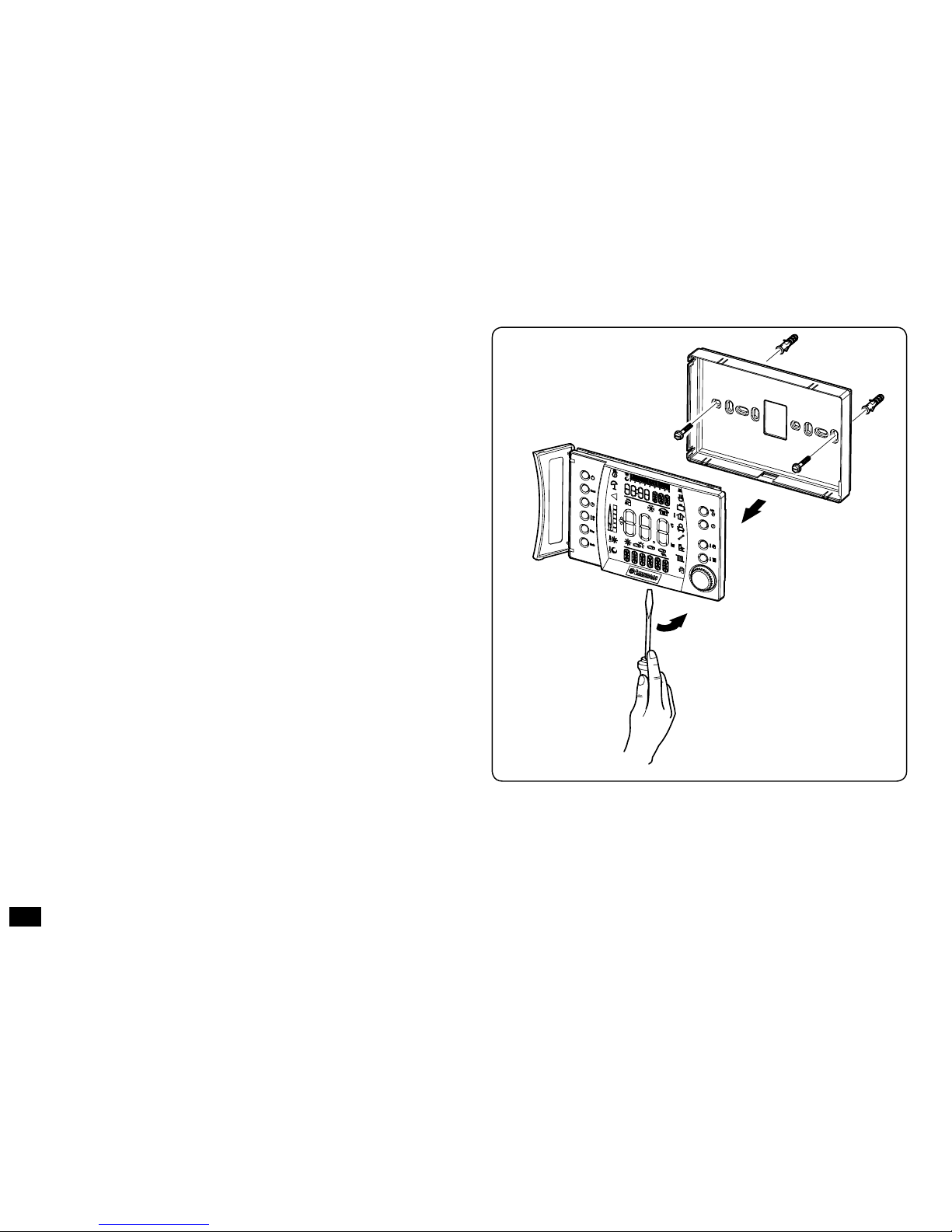
1.2 Installing.
1) Separate the xing template from the body of the Digital
Remote Control, using a screwdriver to lever it out (Fig.
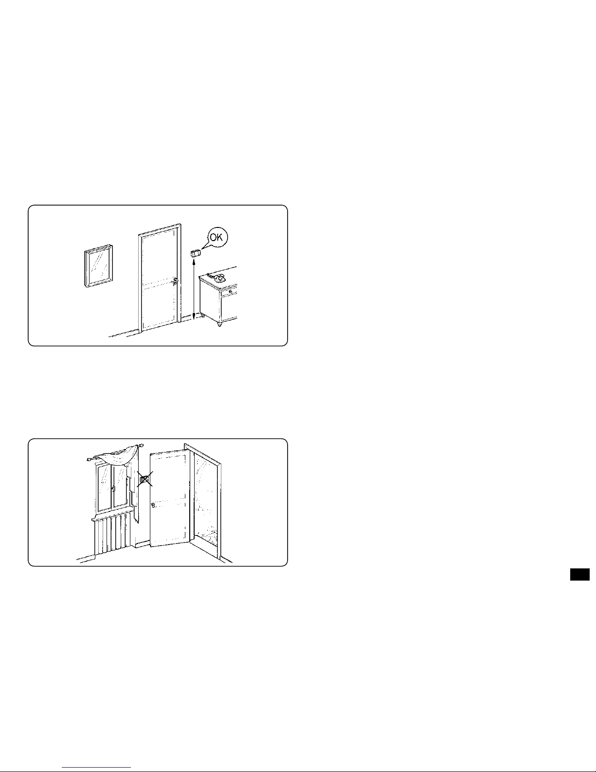
1). Install the Super CAR away from sources of heat and
where the room temperature can be read correctly (Figs. 2
and 3).
Fig. 1
Page 7
7
2) Install the Super CAR directly on the wall using the holes
drilled at the back of it (Fig. 1) or in a recessed box using
the screws supplied with it.
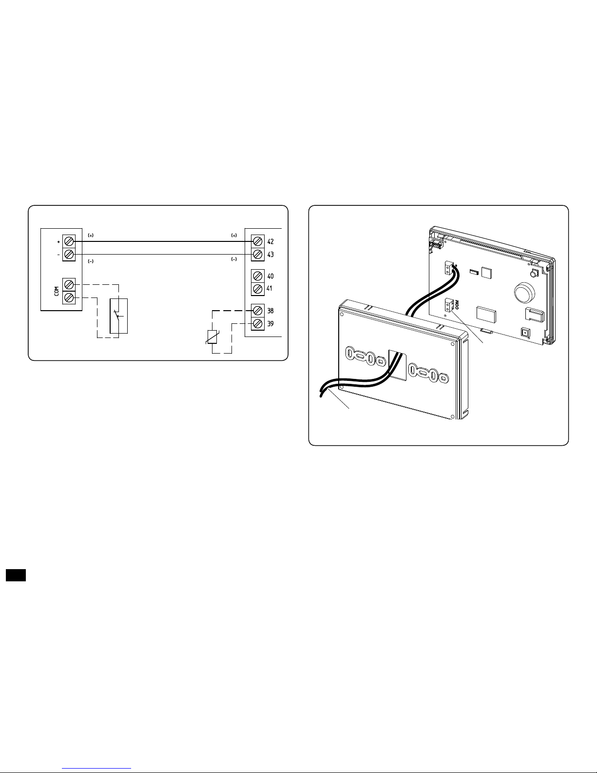
3) Do not do the wiring when the boiler powered (Fig. 4).
Observe conductor polarity (+ and -) and also remove
the jumper on terminals 40 and 41 (if present) on the
boiler’s electronic board.
Note: Refer to the electrical connections in the boiler’s in-
struction handbook.
To connect to the boiler use two wires (Fig. 5) with a
minimum section of 0.50 mm2, maximum 1.5 mm2 and
no longer than 50 metres.
Note: to ensure correct installation use a line dedicated for
connection to the Super CAR in accordance with current
laws on electrical installations. If this is not possible, probable
interference due to other electrical cables could cause the Super
CAR to malfunction.
4) Fix the body of the Super CAR to the support template,
pressing it into place (Fig. 1).
5) After you have powered the boiler wait about 30 seconds
before making the adjustments so communication between
the Super CAR and the boiler can stabilise.
Fig. 3
Fig. 2
NO
1,5 m
Page 8
8
Fig. 5
Fig. 4
Telephone
control connection
(Optional)
Power lead
BOILER
Super CAR
Telephone control
(Optional)
External probe
(Optional)
Page 9
9
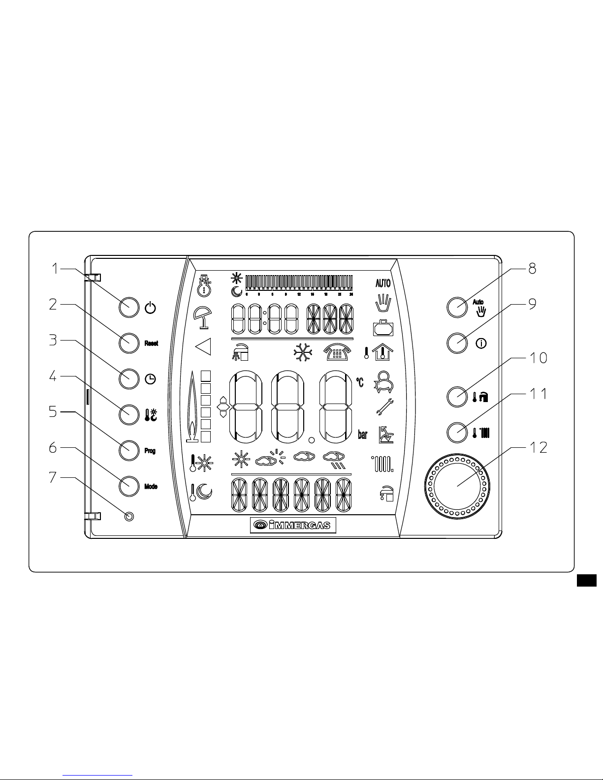
2. DESCRIPTION OF THE CONTROLS
Fig. 6
Page 10
10
1) Winter, Summer push button, O
2) Boiler malfunctions reset push button
3) Push button to set the time and day
4) Push button to set Comfort and reduced room temperature
5) Push button to access the timer programming menu
and the operating mode
6) Push button to access the advanced functions menu
7) Push button to restore factory settings
8) Manual, automatic operation push button
9) Info push button
10) Push button to set the domestic hot water set point
11) Push button to set the central heating set point
12) Parameter selector switch, pressing it to conrm and
store data
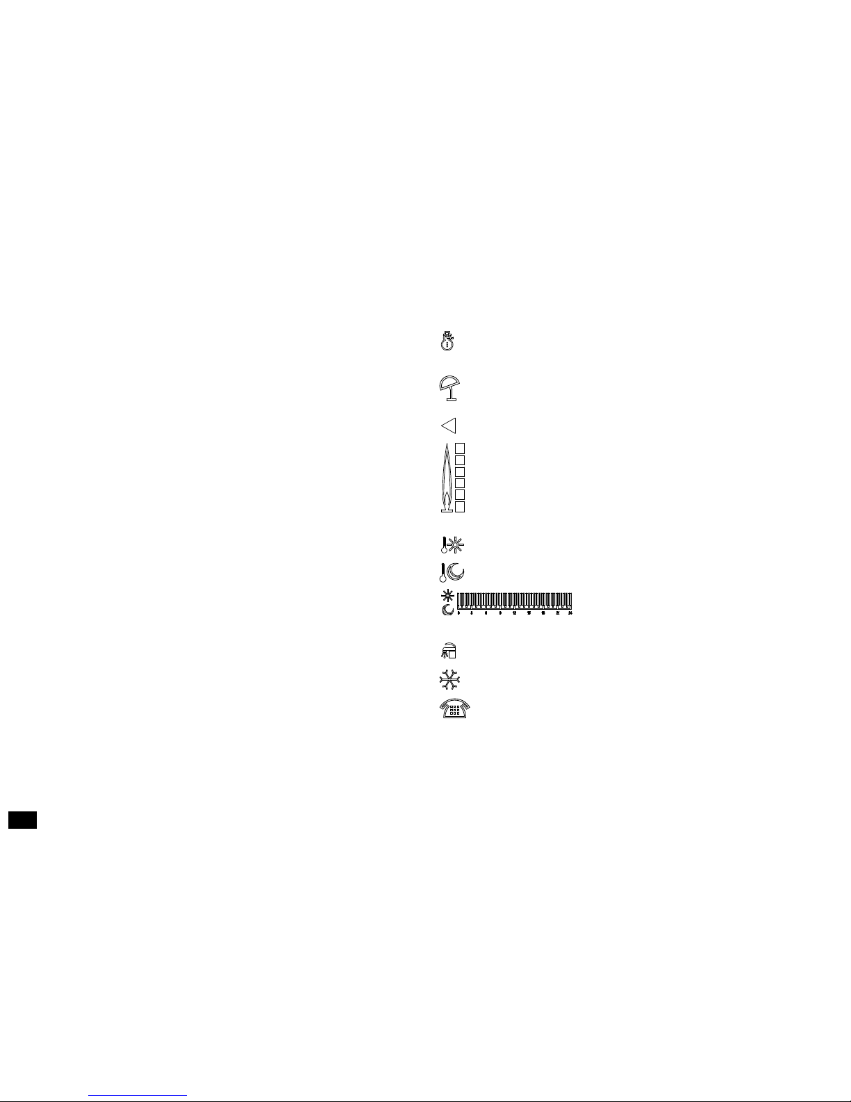
3. DESCRIPTION OF THE DISPLAY
winter - the domestic hot water heating and central
heating functions are enabled
summer - only the domestic hot water heating function
is enabled
Boiler malfunctions Reset function
ame presence symbol and relative power scale
Note: the symbol appears only on boilers with electron-
ics, type “Superior kW”
comfort temperature on
reduced temperature on
hour bar that shows the time when it
is working at comfort and reduced temperatures
aqua celeris on/comfort d.h.w. ongoing
room antifreeze function on
remote operation on
Page 11

11
Note: Some of the icons can have dierent meanings depending on the context; see the following paragraphs to see
which functions are turned on when several icons are present
simultaneously.
4. STARTING
4.1 Programming the current time and day.
Press the push button to access the current time and day
mode.
When you are in the programming mode the parameter to
change starts ashing. Choose the day of the week by turning
the parameter selector and press it to conrm. Do exactly the
same to set the hour and minutes.
visual display of room temperature
and numerical data
visual display of the
weather forecast
description of the state of the functions
being used
working with an automatic programme
working with a manual programme
working with a holiday programme
visual display of the outside temperature
visual display of the indoor temperature
working with the energy saving programme
symbol showing there is a boiler malfunction
working with the external temperature probe on
a room heating request is ongoing
a domestic hot water request is ongoing
Note: the symbol appears only on boilers with electron-
ics, type “Superior kW”.
Fig. 7
Page 12

12
4.2 Selecting the mode.
Depending on the mode selected, Super CAR carries out the
user’s request, displaying the results.
By pressing the push button you go in sequence from standby to working in the summer and winter modes.
e room antifreeze function is also foreseen and works
whatever function is selected.
• Working in stand-by. With Super CAR in the stand-by
mode the word “OFF” appears on the display (see g. 8).
e boiler can work only if there is a room antifreeze request. In this state, however, the current day and time, any
malfunctions, the weather forecast, the percentage of humidity and room temperature are all visually displayed.
Fig. 8
Fig. 9
• Working in the summer mode. By pressing the push
button you go to the summer mode ( ) the Super CAR
enables the boiler to produce domestic hot water only,
turning the room heating mode o (see g. 9). e current
day and time, room temperature, the weather forecast and
the percentage of humidity are shown on the display.
Page 13

13
• Working in the winter mode. By pressing the push
button again you go to the winter mode ( ) the CAR
enables the production of domestic hot water as well as
central heating (see g. 10). In the winter Super CAR can
work automatically or manually - see Chapter 6 for the
description. e current day and time, room temperature,
the weather forecast and the percentage of humidity are
shown on the display.
Fig. 10
Page 14

14
5. SUMMER MODE FUNCTIONS
Only the production of domestic hot water is enabled when
the Super CAR is in the summer mode ( ).
e boiler produces hot water according to the domestic hot
water temperature set on the Super CAR (see g. 11).
5.1 Setting the domestic hot water temperature.
By pressing the push button, the hot water temperature
value set appears on the display. If you turn the parameter
selector while it is being displayed you change the temperature
which is stored by pressing the selector. If the Super CAR is
in the “summer” mode, by pressing or turning the parameter
selector you gain direct access to the domestic hot water
temperature setting window.
Fig. 11
5.2 Domestic hot water timer (for storage tank or
Aqua Celeris).
Use the DOMESTIC HOT WATER TIMER if you wish to
set the temperature of the domestic hot water in the storage
tank at two dierent levels (comfort and reduced) or decide
when Aqua Celeris is to come on during the day. See the special
functions chapter which explains how this is done.
Page 15

15
6. WINTER MODE FUNCTIONS
e heating of domestic hot water and central heating are both
enabled when the Super CAR is in the winter mode ( ).You
can select two main operating modes: automatic or manual
plus a forced automatic timed programme.
- Manual ( ): room temperature is maintained constant
at the value set by the user each time according to his
needs.
- Automatic ( ): room temperature is set at two levels (comfort and reduced) during the day by means of a programme
set by the user.
- Forced automatic ( and ashing): room temperature
is modied momentarily with respect to the automatic
mode up to the next changeover between the comfort and
reduced mode of the automatic programme that was set.
6.1 Working manually.
By pressing the push button (g. 12) the mode alternates between automatic and manual.
Once the manual mode is set the icon turns on on the
display (g. 12).
To set the room temperature wanted simply turn the parameter
selector and the room temperature appears on the display (g.
13). Press the parameter selector to conrm the new value.
When you are on manual any room temperature can be selected
from +5°C to +30°C and will remain constant until it is changed
again or when a dierent operating mode is chosen.
Fig. 13
Fig. 12
Page 16

16
6.2 Working automatically.
Super CAR enables automatic operation where an hourly
programme controls room temperature during the hours
of the day.
e room temperature wanted can be set at two separate levels:
comfort ( ) and reduced ( ) via the , push button and
its distribution throughout the day or week is controlled by
the hour programming function.
Press the push button until the icon turns on on
the display.
Fig. 14
Super CAR is factory set with a standard programme shown
in the following table. If this is dierent from what you need
it can be changed as described in the following chapter.
Note: the system is designed to work at comfort and reduced
temperature levels depending on the hourly programme set.
is means that even when it is working at reduced temperature conditions, if the room temperature measured is below
that set the boiler can turn on.
Days
16°C
20°C
Mon - Fri
(Day 1 - 5)
from 23.00 to 06.00
from 08.00 to 11.00
from 13.00 to 17.00
from 06.00 to 08.00
from 11.00 to 13.00
from 17.00 to 23.00
Sat - Sun
(Day 6 -7)
from 23.00 to 07.00 from 07.00 to 23.00
Fig. 15
Page 17

17
6.3 Working in the forced automatic mode.
If room temperature is changed while in the automatic mode
( ) by turning the parameter selector (2 g. 13), when pressing the parameter selector to conrm, the forced automatic
mode starts (shown when the and symbols start ashing). In this mode room temperature is adjusted to the value
set until the next time the automatic programme set is either
turned o or on. e forced automatic mode can be stopped
by pressing the push button.
6.4 Boiler delivery temperature.
e parameter that regulates maximum boiler delivery temperature can be accessed from the winter function ( ). To
gain access to it, simply press the push button and make
the change, turning the parameter selector. e parameter is
stored, as always, by pressing the selector. e temperature
limits can be set according to the boiler model to which the
Super CAR is connected.
Note: if the maximum boiler delivery temperature limit is set
too low (less than 60°C) it might prevent room temperature
reaching the value wanted.
During normal operation, boiler delivery temperature is
automatically controlled by Super CAR based on the room
temperature set which means the boiler does not work at
the maximum temperature set but does, instead, work at a
lower, but correct, delivery temperature to reach the room
temperature wanted.
If the external temperature probe is installed, the delivery
temperature will be set as described.
6.5 Room antifreeze function.
e antifreeze function has maximum priority over all other
settings. When room temperature drops below 5°C (adjustable, see the special functions chapter) a central heating request
is made at the minimum programmed power. is situation
remains active until there is a variation in room temperature
of 0.6°C equal to 5.6°C measured in the room where the
Super CAR is located.
If the antifreeze function starts, the ashing antifreeze symbol
appears on the display (see g. 16).
Page 18

18
Fig. 16
6.6 Energy saving function.
It is possible to dene a number of hours (from 1 to 99) during
which the system works in the energy saving mode.
In this energy saving mode the boiler carries on working to
maintain the reduced room temperature set on Super CAR.
To gain access to the function press the parameter selector to
see the room temperature setting and while it is being displayed
press the , push button and choose the number of hours
you want to keep the system in the energy saving mode via
the selector. It is reduced every hour. At the end of the hours
set (the counter reaches 0) the functions that were ongoing
before are restored. e icon ashes when the energy
saving function is working.
Note: the antifreeze function is guaranteed also in the energy
saving mode.
If you turn the selector during the function you gain access
to the function counter and not to the room temperature
setting.
6.7 Working in the winter mode with the external
temperature probe.
If an external temperature probe is installed you will be able to
set a delivery temperature correction curve in relation to the
outside temperature. To do this please see the starting procedures explained in the special functions chapter. In this case
when you press the push button the delivery temperature
is shown, calculated in relation to the outside temperature
which can be modied by turning the parameter selector.
Note: the temperature calculated is visually displayed only if
there is a heating request, hence with the symbol on. In
addition, with the room probe on the temperature calculated
depends on the room temperature set. If you wish to limit the
delivery temperature further still, you have to do so via the
“MAX HEAT” parameter in the “Adjustments” menu (Special
Functions chapter).
Page 19

19
7. PROGRAMMING THE SUPER CAR
By programming the Super CAR you can set/modify the
following parameters:
- the comfort and reduced temperature levels;
- hourly, daily and weekly operating programme.
7.1 Setting the comfort and reduced room temperature.
Press the push button to access room temperature programming (g. 17).
Once you are in the parameter, set the comfort temperature
( ) by turning the parameter selector and press it to
conrm; you then return to the normal display. Press the
push button twice to set the reduced temperature ( ) (g.
18). Once set, by turning the parameter selector, press it to
conrm the value set.
Note: If, after having set the parameter, you press the push
button you exit the programming phase without storing the
new temperature.
Fig. 17
Fig. 18
Page 20

20
7.2 Programming working hours.
You enter the programming window by pressing the
push button.
By following the steps described below you will be able to
create or modify the hourly programme.
1) Select the day or group of days by turning the parameter
selector:
- Monday, Tuesday, Wednesday... Sunday (single day)
- Mo - Fr (from Monday to Friday)
- Sa - Su (from Saturday to Sunday)
- Mo - Sa (from Monday to Saturday)
- Mo - Su (from Monday to Sunday)
Note. When working automatically ( ) the 24-hour
bar appears on the display and indicates the dierent
hour phases with Comfort or Reduced temperature
the hyphen on the hour bar stands
for the Comfort mode.
2) Set the working hours with the comfort and reduced
temperature. Up to a maximum of 4 Comfort temperature
periods can be set within the 24 hours, each one with its
turning on and turning o time.
If you are only going to use 3 of these time periods set the
fourth with 24.00 as its turning on and o time.
Once you have selected the day or group of days by pressing
the selector, set the rst working period with the comfort
temperature (ON 1) indicated by the word “ON” at the top
right and “Phase 1” at the bottom; by turning the selector you
select the rst ignition time (corresponding to the time ashing at the top left), pressing the selector to store it. You now
go to the next working period with the reduced temperature
(OFF 1) indicated by “OFF” at the top right and, as always,
“PHASE 1” at the bottom. Once the rst Phase (PHASE 1)
is set you go automatically to the next comfort and reduced
temperature working phases. To programme them, you have
to repeat the steps described previously up to phase 4.
e sequence of the ON and OFF states must always be
sequential; it is not possible, for instance, to set “OFF 2” at
13.30 and “ON 3” at 11.00.
Once you have programmed the day or group of days, the
procedure is exactly the same for the other days.
Page 21

21
8. WEATHER FORECASTS
e Super CAR automatically detects variations in atmospheric pressure where it is installed. It also provides information about the relative humidity in the room and an idea of
what the weather is like.
Attention: the weather forecast is approximate; Immergas
does not hold itself responsible for an erroneous forecast. In
addition, forecasts can only be reliable following a front that
caused a signicant change in atmospheric pressure.
Super CAR visually displays the weather forecast with these
graphical symbols which stand for good
weather, variable, cloudy and rainy respectively.
If the “sun” symbol is displayed during the night it means
good weather.
9. DIAGNOSTICS AND ERRORS
9.1 Diagnostics.
Super CAR controls boiler operation continuously, signalling any malfunctions detected and displaying the relative
error code.
e meanings of the error codes dier according to the boiler
the Super CAR is connected to so please read the boiler’s
instruction manual where you will nd a complete list of the
error codes and their meanings.
In the event of a failure that cannot be reset, contact a qualied technician (the Immergas Technical Assistance service for
instance).
If there is an error the message “ERR>XX” appears on the
display where XX stands for the number that identies the
error code besides the ashing symbol.
Besides the error codes that refer to the boiler operating status,
the Super CAR controls its own operating status indicating
any malfunctions.
Code Description
ERR>CM
Communication error between Super CAR
and the boiler or switching phase between an
evolved (i.e. Superior kW) and normal communication type.
Page 22

22
Code Description
ERR>TP
Error in reading room temperature or value
measured o scale (below 0°C or above 50°C)
ERR>RH
Error in reading relative humidity or value
measured o scale
ERR>PS
Error in reading atmospheric pressure (relative
value) or value measured o scale
ERR>LH
Adjustment algorithm value parameters unsuitable for the heating conditions requested.
Insucient central heating capacity.
9.2 Resetting errors.
In the case of a boiler shutdown that can be reset, the icon
ashes. In this case by pressing the push button and
holding it down for 5 seconds you can send a release signal
to the boiler that starts the boiler working again normally in
just a few seconds, if normal operating conditions have been
restored, it returns to working in the mode set previously.
You have up to a maximum of 5 consecutive attempts at resetting after which you have to wait an hour to have another
5 attempts.
9.3 Resetting the Super CAR.
By means of the general resetting hole (g. 7 page 8) it is possible to reset the Super CAR hardware without losing your
settings (the hour, date and hourly programme).
If you want to restore the original factory settings, use the reset
hole and press the push button. When you release it
the Super CAR will be reset with all factory data.
Page 23

23
10. SPECIAL FUNCTIONS
e push button is used to access a menu for customising
Super CAR to suit your specic needs.
Turn the selector to scroll the list of functions and press it to
select the function wanted.
10.1 Domestic hot water timer (TM SAN).
is is used to set the temperature of the domestic hot water
in the storage tank at two distinct levels (comfort and reduced)
or to dene the daily interval for turning the Aqua Celeris
on. You gain access to the “TM SAN” function by pressing
the selector and setting it on “YES”. Now you have to set
the turning on and o times for the “d.h.w. comfort” temperature. During the turning o period, the domestic water
temperature will be set on the minimum value allowed. e
. icon stays on all the time the d.h.w. temperature is in the
comfort mode. During the setting phase the ON and OFF
comfort temperature time appears on the display as well as the
adjustment bar showing the comfort period you are setting
( ).
Note: for instant boilers, start the function only for models
with evolved electronics, type Superior kW.
10.2 Holiday programme (HOLIDY).
A number of days can be dened (from 1 to 99) during
which the system deactivates both the central heating and the
domestic hot water functions.
e value decreases at midnight with the change of day. At
the end of the days set (the counter reaches 0) all functions
that were on previously are turned back on. e ashing
icon means the holiday function is working.
If this function is activated remotely by the Telephone control,
the boiler is started with the settings given over the phone
stopping the Holiday programme.
Note: the room antifreeze function is always guaranteed even
in the holiday mode.
10.3 Backlit display (DISPLY).
By pressing the parameter selector you can see the backlit display state (ILLUMN) and choose the information to see in the
alphanumerical string (STRING). From these two parameters
you have the following options to choose from:
ILLUMN:
- always on (ON);
- on when setting and using the Super CAR, the display stays
illuminated for 10 seconds (standard setting) (TMR).
Page 24

24
STRING:
- visual display of relative humidity (RH%);
- visual display of the outside temperature (with the optional
external probe installed) (TEX);
- cyclic display of relative humidity and outside temperature
(CIC).
10.4 Adjustment parameter management (REGULT).
By pressing the parameter selector you can see the parameters
for adjusting Super CAR operation:
- Adjustment constant (OFFSET), constant adjustable from
-15°C to +15°C which, when the external probe is installed
(optional), changes the standard setting of the delivery
temperature (0°C) (see g. 19).
Note: if the self-learning function is enabled the Oset
value could be changed automatically.
- e maximum delivery temperature (CH MAX), is the
maximum central heating delivery temperature.
TM-MAX/MIN = Selected delivery temperature range.
TE = Outside temperature.
Note: if the external probe is installed, by pressing the
push button the maximum delivery temperature is
not set but the Oset value is changed.
EXTERNAL PROBE
Delivery temperature reading correction.
Function of the outside temperature and of the user central
heating temperature setting position.
Fig. 19
Page 25

25
- Building dimension and inertia (BUILDG), adjustable
from 1 to 20, standard setting is 10. It establishes the
system’s reaction speed depending on the type of system.
For example:
Value System type
5 system with little thermal inertia
10 system of a normal size with radiators
20
system with a lot of thermal inertia (e.g.
oor system)
- Minimum outside temperature (TE MIN), it denes at
what minimum outside temperature you want to have
the maximum delivery temperature which can be set from
-20°C to 0°C, set at -5°C (see g. 19) (on boilers with
evolved electronics such as Superior kW visualisation only,
settable on the boiler).
- Maximum outside temperature (TE MAX), it denes at
what maximum outside temperature you want to have the
minimum delivery temperature which can be set from +5°C
to +25°C, set at 25°C (see g. 19) (on boilers with evolved
electronics such as Superior kW visualisation only, settable
on the boiler).
- Self-learning (AUTO A), it denes when the self-learning
function is to be activated, ON is the standard setting. is
function allows the Super CAR to adapt the adjustment of
the speed at which room temperature, delivery temperature,
etc., is reached, adapting itself to the room in which it is
installed.
Page 26

26
11. CODE PROTECTED FUNCTIONS
CODE.
ese are advanced character settings (reserved for qualied
technicians) and to gain access to them you have to enter a
4-digit code (code: 1122).
Press the push button and turn the parameter selector
until the word “CODE” appears. Press the selector and enter
the code, selecting the digits by turning the selector and
conrming them by pressing the selector.
You can now see and change the following functions.
11.1 Room probe (AMB ON).
Used to turn the room probe in the Super CAR on or o.
Depending on the parameter setting, it will be possible to
adjust the following options:
- AMB ON set ON (standard setting) a room probe reading
correction factor can be selected is possible.
- AMB CR: room probe reading correction, you can
correct reading of the room probe within a range of +
1.0 - 1.0°C.
- AMB ON set OFF the system will not work by adjust-
ing room temperature but only according to the hourly
programme that has been set. During the times when it is
working in the reduced mode you will be able to select the
following two modes:
- ECONOM OFF: when working in the reduced mode
the Super CAR turns the boiler o.
- ECONOM ON: when working in the reduced mode
the Super CAR reduces the delivery temperature by the
same amount as what is set with the ECONOM option
(adjustable from 0°C to -60°C).
11.2 Modulation (MODUL).
It lets you set Super CAR operation to On/O or Modulating.
With MODUL set on MOD the delivery temperature varies
according to the room temperature that has been set. With
MODUL set on On/O delivery temperature will be maintained constant until the desired room temperature is reached.
(Setting to be done on systems with zone board).
Note: If an external probe is installed, the delivery temperature
is set according to the relative operating curve.
Page 27

27
12. INFO
By pressing the push button you access a menu that lets
you verify the Super CAR operating status.
Turn the selector to scroll the list and press it to select the various items and options. e parameters that can be displayed
are listed below:
- T EXT: outside temperature (if the optional external tem-
perature probe is installed).
- CH TMP: central heating circuit delivery temperature.
- CH SET: value requested for the delivery temperature.
- CH RET: central heating circuit return temperature (only
with boilers where the return probe is installed).
- HW TMP: Storage tank water temperature or d.h.w. outlet
from the boiler.
- CH PRS: System pressure, central heating circuit.
- OTHER>: it visually displays the Super CAR software
version via the SERV option.
Note: the values displayed depend on the type of boiler to
which the Super CAR is connected.
11.3 Antifreeze level (NO FRS).
It lets you set room temperature at which the antifreeze
function starts. Adjustable from 0°C to 10°C; standard setting is 5°C.
11.4 Telephone control (REMOTE).
It lets you set Super CAR operation so that if it is started
remotely it works with the automatic hourly programme if
the setting is AUT. or, vice versa, it works at a continuous
comfort temperature (with no hourly programme) if the
setting is ON.
11.5 Antilegionella function (LEGION).
It lets you start the Antilegionella function which takes storage
tank temperature to 65°C for 15 minutes. You can choose
whether to activate it once a day at 2 o’clock in the morning
(24h), every 7 days on Mondays at 2 o’clock in the morning
(7DY) or turn it o (OFF standard function).
Note: this function must only be turned on when there is a
storage tank and, if necessary, install a thermostat valve on the
outlet of the domestic hot water to avoid scalding.
11.6 Language selection (LANGUG).
It lets you select the Super CAR operating language. You have
a choice of Italian (ITA standard) and English (ENG).
Page 28

28
13. TECHNICAL SPECIFICATIONS
• Supply: ......................................................................................... 24V nominal by means of a bilar communication Bus
• Maximum voltage .......................................................................................................................................................32V
• Power input: ..........................................................................................................................................250 mW nominal
• Room working temperature: ............................................................................................................................. 0 - +40°C
• Warehouse temperature: ................................................................................................................................. -10 - +65°C
• Protection class in compliance with EN 60730: ..............................................................................................................II
• Protection class in compliance with EN 60529: ....................................................................................................... IP 20
• Container measurements (WxHxD): ........................................................................................................ 153 x 112 x 51
• Connection technique: .............................................................................................................................2 polarised wires
• Charge reserve time: ........................................................ 8 hours for hourly counting (with at least 2 hours for charging)
• Max. length of the connecting cable: ................................................................................. 50 m (with 2x0.75mm2 cable)
• Room temperature precision: ................................................................................................................+/- 0.5°C at 25°C*
• NTC room temperature sensor: ..................................................................................................................... 50 k a 25°C
• Clock deviation .................................................................................................................................. +/- 15 minutes/year
* = the indication of the room temperature can be inuenced by where the Super CAR is installed (for instance on a warm
wall, cold wall, height from the oor, etc.).
Page 29

29
13.1 Product specications.
In accordance with Regulation 811/2013 the temperature control device class is:
Class
Contribution to the environmental
heating seasonal energy eciency
Description
V +3% Super Remote Control
VI +4% Super Remote Control coupled to outer sensor
Page 30

30
14. FACTORY SETTINGS
• Operating status ................................................................................................................................................. Stand-by
• Operating programme .......................................................................................................................................... Manual
• Comfort temperature ............................................................................................................................................ 20.0°C
• Reduced temperature ............................................................................................................................................ 16.0°C
• Room temperature on manual ............................................................................................................................... 20.0°C
• Antifreeze ................................................................................................................................................................ 5.0°C
• D.h.w. set point .................................................................................................................................................... 50.0°C
• Max C.H. limit permitted in the boiler ................................................................................................................ MaxRis
• D.h.w. timer ............................................................................................................................................TM SAN = NO
• Holiday programme .............................................................................................................................. HOLIDY = OFF
• Display illumination ................................................................................................... ILLUMIN = TMR (timed for 10s)
• String visually displayed ......................................................................................... STRING = RH% (relative humidity)
• Adjustment constant .................................................................................................................................OFFSET = 0°C
• Building inertia dimension ........................................................................................................................ BUILDG = 10
• Minimum Outside temperature / OTC ................................................................................................TE MIN = -5.0°C
• Maximum Outside temperature / OTC .............................................................................................. TE MAX = 25.0°C
• Room probe ............................................................................................................................................ AMB ON = ON
• Reading Correction .............................................................................................................................. AMB CR = 0.0°C
• Reduction .......................................................................................................................................... ECONOM = OFF
• Reduction factor .............................................................................................................................ECONOM S = 0.0°C
• Modulation ............................................................................................................ MODUL = MOD (Modulating type)
• Telephone control ................................................................................................................................. REMOTE = ON
• Antilegionella: ....................................................................................................................................... LEGION = OFF
• Language: ..................................................................................................................................LANGUG = ITA (Italian)
Page 31

Page 32

Follow us
Immergas Italia
immergas.com
Immergas S.p.A.
42041 Brescello (RE) - Italy
Tel. 0522.689011
Fax 0522.680617
Certied company ISO 9001
Cod. 1.038967 - Rev. ST.002054/001 - 10/15
 Loading...