

Page 1
Instruction and
*1.041494ENG*
recommendation booklet
IE
RAPAX 100 V2
Page 2

Page 3

Dear Customer,
Our compliments for having chosen a top-quality Immergas product, able to ensure well-being and safety for a long period of time. As an Immergas Customer,
you can also count on a qualied aer-sales service, prepared and updated to guarantee constant eciency of your boiler. Read the following pages carefully:
you will be able to draw useful tips on the correct use of the device, compliance of which will conrm your satisfaction with the Immergas product.
For assistance and routine maintenance, contact Authorised Service Centres: they have original spare parts and are specically trained directly by the manufacturer.
General recommendations
All Immergas products are protected with suitable transport packaging.
e material must be stored in a dry place protected from the weather.
e instruction booklet is an integral and essential part of the product and must be given to the new user in the case of transfer or succession of ownership.
It must be stored with care and consulted carefully, as all of the warnings provide important safety indications for installation, use and maintenance stages.
is instruction booklet provides technical information for installing Immergas boilers. As for the other issues related to boiler installation (e.g. safety in the
workplace, environmental protection, accident prevention), it is necessary to comply with the provisions specied in the regulations in force and with the
principles of good practice.
In compliance with the legislation in force, the systems must be designed by qualied professionals, within the dimensional limits established by the Law.
Installation and maintenance must be performed in compliance with the regulations in force, according to the manufacturer's instructions and by an authorised
company, which has the specic technical skills in the system sector, as provided for by Law.
Improper installation or assembly of the Immergas device and/or components, accessories, kits and devices can cause unexpected problems for people, animals
and objects. Read the instructions provided with the product carefully to ensure proper installation.
Maintenance must be carried out by an authorised company. e Authorised Service Centre represents a guarantee of qualication and professionalism.
e device must only be destined for the use for which it has been expressly declared. Any other use will be considered improper and therefore potentially dangerous.
If errors occur during installation, operation and maintenance, due to non-compliance with technical laws in force, standards or instructions contained in
this booklet (or however supplied by the manufacturer), the manufacturer is excluded from any contractual and extra-contractual liability for any damages
and the device warranty is invalidated.
e manufacturer declines all liability due to printing or transcription errors, reserving the right to make any modications to its technical and commercial
documents without forewarning.
Page 4

INDEX
1 Important recommendations. ........................... 5
1.1 Warnings. ............................................................. 5
1.2 installation. .......................................................... 5
1.3 Hydraulic connection. ........................................5
1.4 Wiring. .................................................................5
2 Introducing the product. ...................................6
2.1 Important advice. ................................................6
2.2 Technical specications......................................6
2.3 Dimensions and components. ...........................7
3 Installation. ..........................................................9
3.1 Choosing the place of installation. ................... 9
3.2 Product installation. .........................................11
3.3 Hydraulic connection. ......................................12
3.4 Air intake connection. ......................................12
3.5 Electrical connection. .......................................12
3.6 Water heater wiring diagram. ..........................14
3.7 Commissioning. ................................................14
4 Parameter settings / Use. .................................. 15
4.1 remote panel. .....................................................15
4.2 Description of the symbols. .............................15
4.3 Main menu. ........................................................15
4.4 System settings. .................................................16
4.5 Parameters to be adjusted upon installation. 16
4.6 Selecting the operating mode. ......................... 16
4.7 Display the information ...................................16
5 Recommendations - maintenance and
repairs. ................................................................17
5.1 Advice for the user. ........................................... 17
5.2 Household maintenance. ................................. 17
5.3 Maintenance by approved professionals. .......17
5.4 Troubleshooting support. ................................18
5.5 Work on the water heater. ................................19
5.6 Quick fault diagnosis for use carried out by a
professional technician.....................................20
5.7 Aer-sales service. ............................................ 20
5.8 Scope of application of the warranty. .............20
5.9 Declaration of conformity. ...............................20
6 Product che (in compliance with Regulation
812/2013). .......................................................... 21
7 Parameters for lling in the package che. ....22
Page 5
IMPORTANT
1
RECOMMENDATIONS.
1.1 WARNINGS.
is device may only be used by adult
users whose physical, sensory or mental abilities are not impaired.
Before using this device, this instruction booklet (User section) and/or the
operating instructions should be ready
by skilled technical sta.
Use by incompetent adult staff and
especially by children is forbidden
for safety reasons and due to issues of
correct device operation and warranty.
is device has been designed to serve
one residential housing unit only (and
similar) subject to assessment of the
energy requirement for domestic hot
water; it is not a heating system pursuant to the legislation in force.
1.2 INSTALLATION.
Warning: due to its weight (57 kg), this
device must be handled with care to
avoid injury to persons or damage to
property and to the product itself. Installation must therefore be performed
taking into account the following
instructions:
- Install the device in a frost-free room.
The warranty does not cover any
device breakdown caused by excessive pressure due to the safety valve
blocking because of ice.
- Ensure the wall on which the device
is to be installed is suitable to withstand the device's own weight and
that of the water content (100 litres
approximately). It is recommended
to perform a structural assessment
by the designer of the dwelling.
- If the storage tank is mounted on a
false ceiling, under the roof or above a
living area, it is mandatory to install a
drip tray to be connected to the drain.
- Suitably aerate the installation room
in the event the device is to be installed in a room and/or in a position
where the ambient temperature is
always higher than 35°C.
- is device is intended for use up to
a maximum height of 2000 m.
- Position the device in an accessible
area and at such a distance from the
wall to permit correct maintenance /
accessibility (Paragraph 3.1).
- Refer to the installation diagrams
(Paragraph 3.1).
Caution: failure to comply with recommended installation procedures,
especially a room volume below the 20
m3 minimum, may signicantly reduce
system performance.
- It is recommended to provide suitable shut-o valves on the hydraulic
connection to allow for any routine
and extraordinary maintenance operations which might require emptying/
lling the water heater.
- In order to prevent any stability and
safety issues, it is obligatory to secure
the water heater on the wall using the
fastening anchors supplied.
1.3 HYDRAULIC CONNECTION.
It is mandatory to install a safety device,
set to be triggered at 0.7 MPa (7 bars)
(not supplied with the water heater),
sized 3/4”, compliant with standard
EN1487 as amended and added, and
in any case compliant with local regulations in force, to be tted to the cold
water inlet of the water heater.
e safety device must be protected
from ice.
e safety unit must be tted with a
discharge device (overpressure) to
be operated regularly to remove any
limestone deposits.
It must also be checked regularly to
ensure it is not blocked.
e pressure reducer (not supplied as
standard) is required when the water
mains pressure exceeds 0.5 MPa (5
bars) and must be mounted on the
main water supply line.
e safety unit must also be connected
to an open drain pipe, in a frost-free
environment, with a permanent downward gradient, to remove any expansion water from the heating process, or
drainage water from the water heater.
To perform any discharge operations
of the water heater, strictly adhere to
the following sequence:
- Disconnect the device from the electrical supply voltage.
- Disconnect the device from the mains
water supply (cold water).
- Open the hot water tap.
- Actuate the discharge device of the
safety unit.
1.4 WIRING.
Before removing the cover of the water
heater, always ensure the power is dis-
connected, to prevent any risk of injury
due to electric shocks.
e following must be provided upstream of the electrical system:
- A circuit breaker or 16A multi-pole
fuse with contacts compliant with
regulations in force.
- A 30 mA dierential circuit breaker.
Should the power cable be found to
be damaged for any reason, it must be
replaced by the Aer-sales Support,
and/or in any case by skilled and qualied sta.
e water heater must be connected to
earth according to the methods set out
by the regulations in force.
A special terminal, suitably marked
is provided for the specic purpose.
is manual is supplied jointly with the
water heater; in the event of loss it may
also be obtained from the Authorised
area Support service or be downloaded
from the suitable website.
5
Page 6
INTRODUCING THE
2
PRODUCT.
2.1 IMPORTANT ADVICE.
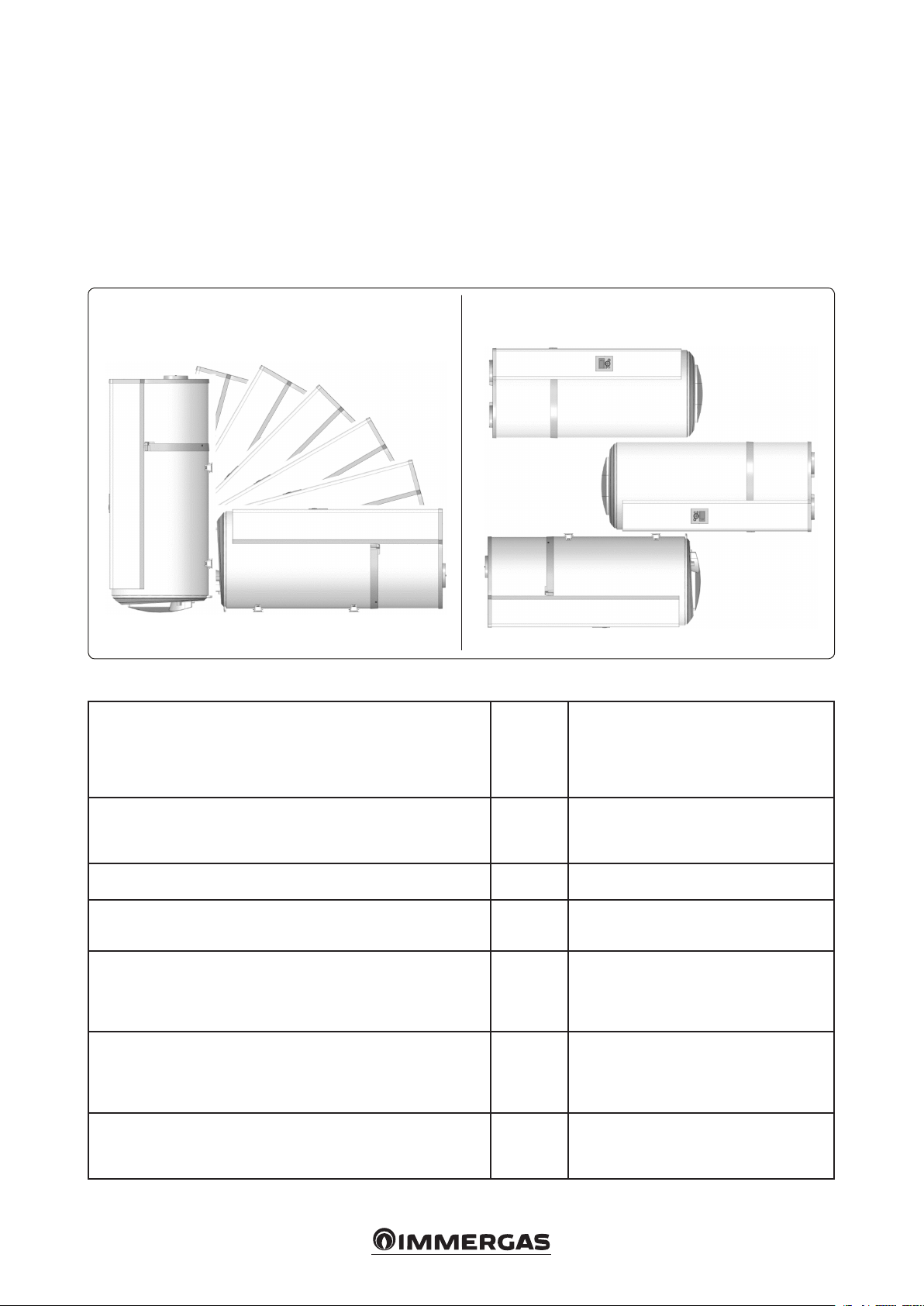
Transport, handling and storage. e product
may be transported upright on a pallet, or rotated
by 90° on its side
The appropriate side is shown clearly on an
information label on the product packing box.
It is forbidden to transport the product lying on
its other sides as it could irreparably damage it.
Note: follow the transport and maintenance recommendations on the water heater’s packaging.
e product warranty is rendered null and void
if the above instructions are not complied with.
e manufacturer declines any liability for any
faults to the product resulting from transport or
handling not complying with the above recommendations.
Under no circumstances may this product be
stacked (Fig. 2-1).
Safety directives. The installation work and
commissioning of thermodynamic water heaters
can be hazardous due to high pressure and live
electrical parts.
ermodynamic water heaters must be installed,
commissioned and serviced by trained and
qualied sta only.
POSITIONS ALLOWED DURING TRANSPORT
2.2 TECHNICAL SPECIFICATIONS.
Dimensions
Empty weight
Tank capacity
Hot + cold water tting
Anti-corrosion protection
Maximum operating pressure
Electrical connection (voltage/frequency)
Max total power absorbed by the device
Max power absorbed by heat pump
Power absorbed by auxiliary electrical unit
Setting range of the water temperature of the heat pump
Temperature range for using the heat pump (air temperature)
Diameter of intake and exhaust ducts
Air ow rate without ducts
Load losses acceptable on ventilation circuit, without aecting performance
R134a refrigerant charge
Coolant
Coolant mass
Coolant volume
Amount of hot water at 40°: V40td in 8h (HC) / 14h (HC+6h)
Coecient of performance (COP)
Power absorbed at steady speed (Pes)
Heating time(th)
Reference temperature(Tref)
Air ow rate
Coecient of performance (COP)
Power absorbed at steady speed (Pes)
Heating time(th)
Reference temperature(Tref)
POSITIONS NOT ALLOWED DURING TRANSPORT
mm
kg
l
bar
W
W
W
°C
°C
mm
m3/h
Pa
kg
kg/l
Ton CO2 Eq.
l
-
W
h.min
°C
m3/h
-
W
h.min
°C
H 1234 x L 522 x D 538
57
100
3/4’’ M
Magnesium anode
8
230 V single-phase 50 Hz
1550
350
1200
from 50 to 62 (temperature factory setting 52°C)
from -5 to +43
125
160
25
0.6
R134a
0.006
0.86
151 / 289
2.47 - M
20
7 h 27
52.8
162.7
2.75 - M
18
6 h 25
52.5
2-1
6
Page 7
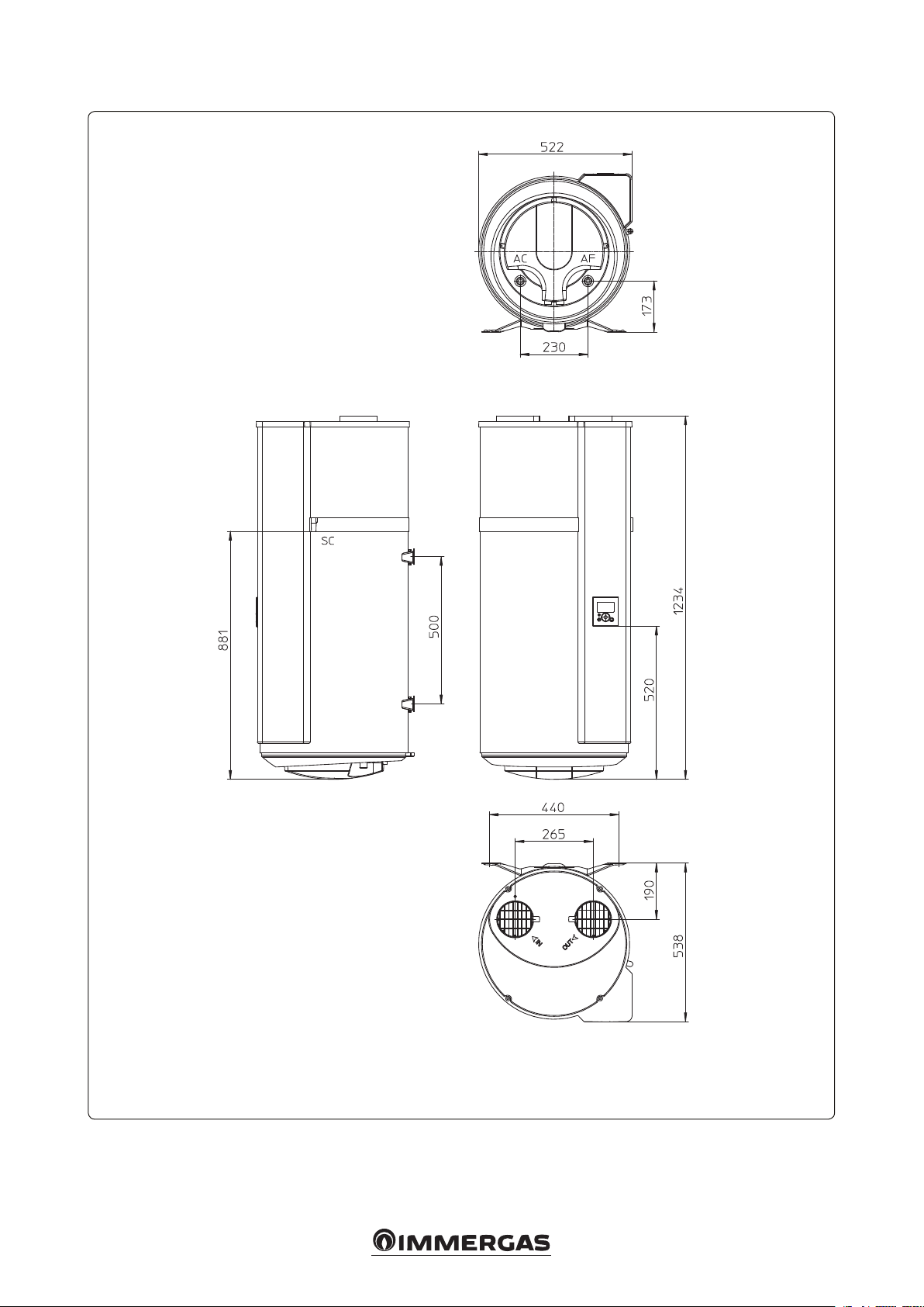
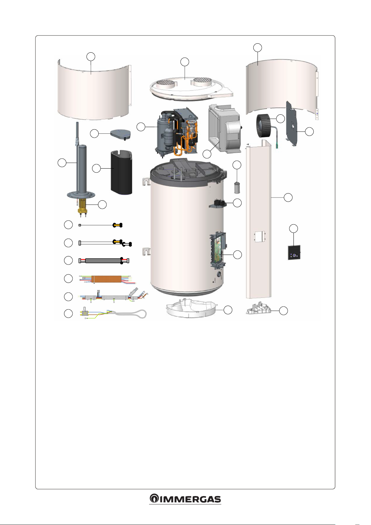
2.3 DIMENSIONS AND COMPONENTS.
Key:
AC - Domestic hot water outlet 3/4” M
AF - Domestic cold water inlet 3/4” M
SC - Condensate drain
2-2
7
Page 8
3
1
2
10
8
5
11
9
4
6
24
7
18
19
20
21
22
23
Key:
1 - Front cover
2 - Cover
3 - Rear cover
4 - Heating unit (Resistance + Anode)
5 - Casing cover
6 - Compressor casing
7 - Electrical resistance
8 - Compressor
9 - Fan casing
10 - Fan
11 - Fan support plate
12 - Front column
13 - Control unit
14 - Condenser 1.5-2.5-2.7F
15 - P.C.B.
16 - Cap
17 - Bottom part cap
18 - Water probe wiring 1
19 - PDC probe wiring 2
20 - Interface wiring
21 - Electrical integration
22 - Compressor wiring
23 - Fan wiring + terminal block
24 - Condenser 10F
Not shown: manual, dielectric connection, condensate draining pipe, safety unit.
16
14
12
13
15
17
2-3
8
Page 9

INSTALLATION.
3
3.1 CHOOSING THE PLACE OF
INSTALLATION.
Resistance of the wall • Withstands a load of at least 300 kg (water heater xing surface)
Note: only install a water storage tank under the water heater when this is positioned above in
residential buildings.
e installation area shall be suitable for protection index IPX1B, as set forth in IEC 64-8
Non-ducted or
semi-ducted conguration
Type of installation room
Room examples
Volume of room where air is extracted
Temperature of water heater installation
room
Air inlet temperature
• Unheated room, characterised by temperature
exceeding 5°C and preferably insulated from
the home's heated rooms.
• Recommended room = underground or basement, room where the temperature is higher
than 10°C all year round.
• garage, boiler room (with the exception of
rooms where type B generators are installed),
basement oor, ironing room, etc.
• Volume > 20 m
• from 5°C to 43°C.
• -5°C to 43°C.
3
• Room that is at least frost-free.
• Recommended room = living space (the heat
loss from the water heater is not wasted), close
to the outer walls.
• Do not install close to sleeping areas because of
the noise produced.
• laundry room, cellar, cupboard in entrance hall,
etc.
• /
• > 1°C.
• -5°C to 43°C.
Ducted conguration
Ceiling height
Surface area required
RECOMMENDED CONFIGURATIONS.
• 1st conguration: installation without duct in
unheated room (Volume > 20 m3) (Fig. 3-1).
INTERNAL/INTERNAL parameter (Para-
graph 4.5).
Examples of unheated rooms:
- Garage: Recovery of free calories released by
car engine when turned o aer running, or
other electrical appliances operating.
Min.
200 mm
• > 2.00 m.
• 2.10 m2.
• e wall must be perpendicular.
- Laundry room: dehumidifying the room
and recovery of waste calories from washing
machines and tumble-dryers.
- Room in basement: recovery of free calories
released by the oor and walls of the basement.
• > 2.00 m.
• 2.10 m2.
• e wall must be perpendicular.
Note: observe the minimum distance indicated
to prevent air recirculation.
Note: observe a space of 450 mm in front of the
electrical appliance, so that the water heater can
be accessed for maintenance work.
Min.
600 mm
Example of
installation without
ducts
Min. 400 mm
3
>20 m
Except for the volume of
bulky waste
Room temperature between 5 and
43°C, except for operation of the
water heater
522 mm
9
Min.
120
mm
3-1
Page 10

• 2nd conguration: installation in a heater or
unheated room, with ducts (Fig. 3-2).
EXTERNAL/EXTERNAL parameter (Par-
agraph 4.5).
Recommendations:
- Comply with maximum duct lengths (Para-
graph 3.4).
- Use rigid or semi-rigid pipes.
- Provide air inlet and outlet grids to avoid
ingress of foreign bodies. Note: manually
shuttered air inlet and outlet grids are forbidden.
3-2
Min.
100 mm
Note: observe a space of 450 mm in front of the
electrical appliance, so that the water heater can
be accessed for maintenance work.
CONFIGURATIONS IN CERTAIN CONDITIONS (subject to assessment).
• Installation in unheated room, with 1 duct
only (volume > 20 m3) (Fig. 3-3).
INTERNAL/EXTERNAL parameter (Para-
graph 4.5).
Possible consequence:
- In the event of installation with air intake in
the same room and expulsion through a duct,
the ventilation openings must be sized with
a minimum diameter of 125 mm.
Note: in winter, the inlet air will be colder than
that discharged by the water heater, which will
increase room cooling.
Note: observe a space of 450 mm in front of the
electrical appliance, so that the water heater can
be accessed for maintenance work.
3-3
Min.
670 mm
Min.
200 mm
Example of
installation with
ducts
Mandatory air
inlet
Ø 125 mm
Room at minimum
antifreeze
522 mm
Duct on air outlet
Min.
120
mm
Min.
670 mm
Example of
installation with 1
exhaust duct
Room temperature between 5 and
43°C, except for operation
of the water heater
Min.
522 mm
120
mm
10
Page 11

FORBIDDEN CONFIGURATIONS.
Forbidden installation congurations Associated risks
e water heater takes air from a room containing a
paid heat source used for heating this room.
Connection to a controlled mechanical ventilation
system (CMV).
Connection to an attic.
duct which intakes air from the outside, conveying
cold air inside.
Connection to a geo-thermal system.
Excessive system consumption: the water heater no longer uses free calories, but uses those
produced by other devices connected to other energy sources.
e air ow rates in the thermodynamic water heater are incompatible with those of a CMV.
Furthermore, the CMV ducts may convey greasy vapour and dust, potentially harmful for
the duration in service of your water heater.
In the presence of inadequate insulation between the building and the relative attics, this
type of installation may increase the thermal loss of the building.
In extreme cases, condensate might form on the ceilings of the rooms under the attic due
to its cooling.
ere is a greater risk from falling objects and dust ingress to the water heater in this
conguration, which could reduce its life expectancy.
Signicant loss of the coecient of performance (COP) and much greater cooling of the
room.
Excessive loss of load, and problems balancing the two fans in series.
High risk of clogging the evaporator.
Other prohibitions:
- Do not connect the device's fan to a tumble-dryer
- Avoid very dusty rooms
- Do not extract air containing solvents or explosive materials.
- Do not connect the device to a suction hood
used to extract greasy or polluted air.
- Do not install the water heater in a room exposed to frost
- Do not place any objects on the water heater
- In non-ducted or semi-ducted conguration,
do not place it in a room where an open chamber heat generator is installed (type B).
3-4 3-5
3.2 PRODUCT INSTALLATION.
1 - Take the water heater to the place of installa-
tion.
e device has various handholds to help
move it to the place of installation.
Use the bottom and top handholds to carry
the water heater to its place of installation.
2 - Open the packaging.
3 - Separate the boiler from the pallet and place
it next to the hydraulic connection.
e water heater must be installed on a
perpendicular wall (± 1°) or on smooth at
surface (± 1°).
4 - If the wall is load-bearing (concrete, stone,
bricks) (Fig. 3-4), anchor with Ø10 mm bolts
or drill holes for Ø10 mm MOLLY bolts.
5 - If the wall is not load-bearing (Fig. 3-5) it is
mandatory to put the water heater on a mount
(optional). Put the water heat on the mount
to trace the xing points. Drill the holes and
reposition the water heater. e top bracket
must be secured (using a Ø10 mm anchor
at least, depending on the wall) to prevent it
from tipping over.
11
Page 12

3.3 HYDRAULIC CONNECTION.
Connection to the cold water inlet.
Before connecting the water supply, it is essential
to clean the pipes thoroughly, to avert the risk of
any metal or other particles entering the water
heater tank.
It is mandatory to install a safety device, set to
be triggered at 0.7 MPa (7 bar) (not supplied
with the water heater), sized 3/4”, compliant with
standard EN1487 as amended, and in any case
compliant with local regulations in force, to be
tted to the cold water inlet of the water heater.
e safety device must be protected from ice.
Note: no hydraulic ttings (stop valve, pressure
reducer, etc.) must be placed between the safety
unit and the cold water inlet of the water heater,
except for a copper pipe.
Connect the safety unit to an open drain pipe,
in a frost-free environment, with a permanent
downward gradient, to remove any expansion
water generated by the heating process or drainage water coming from the water heater itself.
e pipes used must withstand a temperature of
100°C and a pressure of 1 MPa (10 bar).
When the inlet water pressure exceeds 0.5 MPa (5
bar), a pressure reducer is required (not supplied
as standard).
e pressure reducer must be installed at the
beginning of the main distribution network.
A pressure of 0.3 to 0.4 MPa (3 and 4 bar) is
recommended.
Connection to the hot water inlet.
Note: do not connect the hot water directly to
copper pipes, in order to avoid copper/iron galvanic coupling (risk of corrosion). It is therefore
obligatory to t a dielectric tting on the hot
water outlet (supplied with the device).
Any corrosion on the threads of the hot water
outlet tting, due to the tting supplied not
being used, shall void the product warranty.
In the event pipes in synthetic material have been
used (e.g.: PER), we strongly recommend installing a thermostatic control device water heater
outlets and set it according to the performance
of the material used.
Note: the use of D.H.W. recirculation is not feasible: this method causes water destratication
in the tank and makes the heat pump and the
electrical resistance work more.
Removing the condensate.
Note: cooling of the circulating air in contact
with the evaporator results in the water contained
in the air condensing. The condensed water
owing down the back of the heat pump must
be removed from it and conveyed into suitable
plastic pipes.
On the basis of air humidity, up to 0.25 l/h of
condensate may be formed. e condensate
run-o must not be conveyed into the drain,
since the ammonia fumes that ow back from
the drain could damage the heat exchanger ns
and parts of the heat pump.
It is therefore obligatory to t a siphon for the
discharge of waste water (do not use the pipe
supplied under any circumstances to make a
siphon).
3.4 AIR INTAKE CONNECTION.
When the volume of the room where the water
heater is installed is less than 20 m3, the device
may be connected to air ducts with 125 mm diameter. If these ducts are not insulated, condensate might form in them during device operation.
It is therefore essential to choose insulated
air ducts.
Poor-quality air ducts (crushed, too long, or
with too many bends, etc.) may cause a loss of
performance.
Therefore flexible ducts are definitely not
recommended.
Note: if there are connections to the ducts, adjust
fan settings accordingly.
Note: the overall head loss on ducts and ttings
for discharge and intake of air must be less
than 70 Pa. Calculate the pressure drop using
the table below, according to the proposed duct
accessories.
For installation without ducts, the direction of
the grids can be altered to direct the air ows.
To do this, unscrew the grids and screw them
back in one of the other 2 positions provided.
It is forbidden to direct the grids facing each
other (Fig. 3-6).
3.5 ELECTRICAL CONNECTION.
Note: the water heater can be electrically con-
nected only aer being lled with water.
Note: do not t a programming clock or timing
devices that may interrupt the device's supply
voltage upstream of the water heater’s electrical
connection.
e water heater can be connected and operated
only with single-phase 230V AC power supply.
Connect the water heater with a cable with
conductors having a cross-section of at least 1.5
mm². Installation shall consist of:
- A circuit breaker or 16A multi-pole fuse with
contacts compliant with regulations in force.
- A 30 mA dierential circuit breaker.
If the power cable is damaged, for safety reasons
it must be replaced by the manufacturer, the
aer-sales service or similarly qualied sta.
Note: earthing is obligatory.
Do not connect the supply voltage directly to the
electrical resistance.
e safety thermostat with which the electrical
integration is tted must not be tampered with; if
required, it may be repaired/serviced exclusively
by skilled and qualied sta, according to the
instructions provided by Immergas. Failure to
comply with this clause shall void the warranty.
e device must be installed in compliance with
the provisions of the regulations in force.
3-6
Number of bends
0 bends 10 m 21 m
1 90°
elbow tting
2 90°
elbow ttings
(*) semi-rigid ducts - (**) rigid ducts
Overall length of the ducts* with air outlet and
inlet mounted on the wall
8 m 17 m
6 m 13 m
Overall length of the ducts** with air outlet and
inlet mounted on the wall
12
Page 13

Photovoltaic self-consumption contact.
e water heater is equipped with a contact to
fully exploit the electricity produced by the PV
system, in order to accumulate thermal energy
within the storage tank (self-consumption).
Having an inverter/electronic device which
supplies a signal when PV production exceeds
a certain value, when this contact is closed the
water heater is triggered in heat pump mode to
heat the DHW up to 62°C.
When the photovoltaic contact opens, the system
returns to the previous settings.
Wiring diagram
e instructions for removing the front cover and
for accessing the terminal block can be found in
paragraph 5.5.
e photovoltaic station must be wired to the
appropriate connector provided (I1) (Fig. 3-10).
To pass the photovoltaic station’s connection
cable, a hole must be drilled in the bottom cap;
the point where the hole is to be drilled is marked
(Fig. 3-8).
3-8
Note: earth connection is mandatory.
Example of connection to a photovoltaic system
AC junction
box
Inverter
3-7
PV panel
230V~ - 50Hz signal
3-9
13
Page 14

3.6 WATER HEATER WIRING DIAGRAM.
3-10
Supply voltage
230 Vac
50Hz
Key:
1 - Water heater board
2 - Evaporator probe
3 - Air inlet probe
4 - Fan condenser - second speed
5 - Fan
6 - Fan engage condenser
7 - Safety thermostat
3.7 COMMISSIONING.
Filling the water heater.
- Open the hot water taps.
- Open the cold water tap on the safety device
(ensure the unit emptying valve is closed).
- Run the hot water from the taps then close
them: the water heater is now full.
- Check water tightness of the pipe ttings.
- Check correct operation of hydraulic devices by
opening the discharge valve of the safety device
to eliminate any residues from inside the relief
valve.
Θ>
8 - Immersion heater
9 - Domestic hot water sensor
10 - High pressure sensor
11 - Compressor protection thermostat
12 - Compressor engage condenser
13 - Compressor
14 - Hot gas valve
15 - Control panel
Commissioning.
Note: if the water heater has been tilted, wait at
least 1 hour prior to commissioning.
- Turn on the water heater.
- Check that the screen (4 Fig. 4-1) does not
display errors.
- During rst power-up, the adjustment instructions are displayed on the screen. Follow the
on-screen instructions carefully to set parameters (date and time, air ducts, installation, photovoltaic, operating time slots, anti-legionella
system).
- Setting the programming time slots:
In the “heating mode” menu, select the “HP 24
hours, programmable resistance” or the “programmable HP and resistance” option where
you have the choice of setting two time slots.
Colour codes key:
BK - Black
BL - Blue
BR - Brown
GY - Grey
YE - Yellow
GN - Green
G / Y - Yellow / Green
RD - Red
WH - White
e start time of the time slot and the duration
of the slot can be set with the arrow keys and ok
to conrm. e total minimum and maximum
heating periods between the two time slots are
respectively 12 and 20 total hours.
- Aer setting the parameters, check operation
of the water heater.
To return to the settings, refer to the "System
Settings" or "Setup Parameters" sections.
14
Page 15

MENU
Informazioni
Impostazioni
PARAMETER SETTINGS /
4
USE.
4.1 REMOTE PANEL.
Key:
1 - Main parameters key that
conrms and saves data when
pressed
2 - Key to open the settings
3 - Key to return to the previous
screen
4 - Display
5 - Key to temporarily increase hot
water production
6 - Up arrow: increases values/
browses through menus
7 - Down arrow: reduced values/
browses through menus
4
2
1
6
4.2 DESCRIPTION OF THE SYMBOLS.
Symbol Description
Forced start set
Absence set / in progress
Hot water set-point temper-
ature
Stand-by
Electrical integration in operation
Heat pump in operation
Anti-legionella cycle
Reception of a signal at the inlet
of the photovoltaic system
• BOOST function ( ).
Press the key (5 Fig. 4-1) to increase the production of hot water regularly.
Set the number of the BOOST operation days
(from 1 to 7). At the end of the chosen period,
the water heater resumes operation with the
initial settings. e BOOST can be interrupted
at any time:
BOOST pause
.
5
4.3 MAIN MENU.
Open the settings by pressing the “Access key”
( ) (2 Fig. 4-1) and follow the on-screen
instructions (4 Fig. 4-1). Browse through the
menu by pressing the “down arrow” (7 Fig. 4-1)
to reduce the values or the “up arrow” (6 Fig. 4-1)
to increase the values.
Press the main key in the centre (1 Fig. 4-1) to
conrm.
4-2
Modalità MANUALE
Modalità ASSENZA
• OPERATING mode ( ).
Choose the operating mode.
Select AUTO or MANUAL (see paragraph 4.6
"Operating modes").
• ABSENCE mode ( ).
Program an absence.
It allows you to indicate in the water heater:
- a permanent absence starting from the
current date;
- a programmed absence (set the start date of
the absence and the end date). On the eve of
your return, an anti-legionella cycle is activated. In this period, the water temperature
is kept above 15°C. e function can be in-
terrupted at any time:
Disable absence
3
7
4-1
• Information ( ).
- Display the energy savings.
It allows you to view the utilisation rate of
the heat pump and electrical integration
over the last 7 days, the last 12 months, from
commissioning.
- Display power consumption.
It allows you to view energy consumption in
kW/hour, in recent days, in recent months,
in recent years.
- Display the budget parameters.
It allows you to view all the settings recorded
in the water heater.
• Settings ( ).
- Set the time and date.
Set the day and then conrm. en set the
month, year, hour and minutes.
- Set the operating time slots
It lets you dene the time slots in which the
device is authorised to start.
- Set the language.
French, English, Dutch, Spanish, Portuguese, German, Italian and Polish.
- Connections.
It allows you to turn o the support of electrical integration.
.
15
Page 16

4.4 SYSTEM SETTINGS.
Access to the system settings: ( ) + Settings.
• Date and time.
Set the day and then conrm. Do the same for
the month, year, hour and minutes.
• Heating mode.
is parameter denes the operating time slots
of the heat pump and of the electrical integration according to the hot water requirements:
24/24 continuously
th e day.
Programming
riods.
• Setting the programming time slots.
In the “heating mode” menu, select the “HP
24 hours, programmable resistance” or the
“programmable HP and resistance” option
where you have the choice of setting two time
slots. e start time of the time slot and the
duration of the slot can be set with the arrow
keys and ok to conrm. e total minimum
and maximum heating periods between the
two time slots are respectively 12 and 20
total hours.
• Language.
Possible settings in French, English, Dutch,
Spanish, Portuguese, German, Italian and
Polish.
• Connections.
It allows you to activate or not the electrical
integration support. If it is o, the device will
never use the electrical integration; in case
of low temperatures, a shortage of hot water
is possible.
4.5 PARAMETERS TO BE ADJUSTED
UPON INSTALLATION.
(If not set at the time of commissioning)
e installation parameters can be accessed in
INSTALLER MODE.
Press “Menu” (2 Fig. 4-1) and “Up arrow” at the
same time for 5 seconds (6 Fig. 4-1).
To exit the installer mode, proceed in the same
way or wait for 3 minutes.
Start at any time of
Start in scheduled pe-
Access to the system settings: ( )
• Block
is mode enables continuous operation only
with the boost.
• Hot water.
- Heating mode
is parameter denes the operating time
slots of the heat pump and of the electrical
integration according to the hot water
requirements:
HP 24h / ELEC
24h
HP 24h /
ELEC Prog
HP Prog /
ELEC Prog
- Anti-legionella.
It allows you to turn on the water disinfection function several times a month. e
water temperature reaches 62°C 1-4 times
a month depending on the desired setting.
- PV Photovoltaic system.
is parameter is used to activate the device
coupled with a photovoltaic system. is
operating mode generates the forced start
of the heat pump when the water heater
receives a signal coming from the photovoltaic system. e setting automatically
returns to the previously selected mode
aer 30 minutes if the photovoltaic system
signal is lost. While receiving the signal the
set point temperature is automatically set at
62°C (not adjustable).
- Emergency mode.
Enabling this mode allows continuous operation only with the electrical integration.
- Additional Electricity BOOST (electrical
integration).
It allows you to activate or not the electrical
integration support. If it is o, the device
will never use the electrical integration; in
case of low temperatures, a shortage of hot
water is possible.
• Ducting (aeraulic operation).
is parameter denes the aeraulic connection
type realised:
Inside / Inside
Outside /
Outside
Inside /
Outside
Start at any time of
the day
Start the heat pump
at any time of the
day, start the electrical integration at the
programmed times
Start in programmed
periods.
Suction and return not
connected to air ducts
(ambient air)
Suction and return connected to air ducts (outside air)
Return connected to an air
duct (semi-ducted)
Settings
4.6 SELECTING THE OPERATING
.
MODE.
Press ( ) to access the
• In AUTO mode.
is operating mode automatically manages
the energy choice that allows maximum savings while guaranteeing an adequate comfort
in terms of hot water. e water heater analyses the consumption of the previous days to
adapt the production of hot water according
to needs. It reacts to unexpected events to
ensure hot water by switching the heat pump
on. erefore, the set point temperature is
automatically adjusted between 50 and 62°C
according to the consumption prole. e
Water heater operates preferably through the
heat pump. e electrical integration can be
automatically selected to ensure a sucient
volume of hot water.
• MANUAL mode.
is mode allows you to dene the desired
amount of hot water by choosing the set
point. is set point is also represented as an
equivalence of number of showers (about 50
litres of hot water).
If the ECO mode is not active, the water
heater favours operation of the heat pump
only. However, if the air temperature is low
or consumption is substantial, the electrical
integration can be authorised as a support at
the end of heating to reach the temperature
set. If the ECO mode is active, the water
heater works only with the heat pump with
an air temperature ranging from -5 to +43°C.
Therefore electrical integration is not authorised at the time of heating. is feature
optimises the savings, but can cause hot water
shortages. Regardless of the ECO adjustment,
if the air temperature exceeds the operating
time slots, the electrical integration will be
automatically selected to ensure a sucient
volume of hot water.
• BOOST mode.
This mode activates the heat pump and
electrical integration simultaneously at the
maximum set point of 62°C.
• ABSENCE mode.
is mode maintains the domestic hot water
temperature above 20°C using the heat pump.
Electrical integration can be activated if the
heat pump is not available.
4.7 DISPLAY THE INFORMATION
Open the “Info” menu to:
• Display the energy savings.
It allows you to view the utilisation rate of
the heat pump and electrical integration
over the last 7 days, the last 12 months, from
commissioning.
• Display the power consumption.
It allows you to view energy consumption
in kw/hour, in the last 7 days, in the last 12
months, from commissioning.
• Display the budget parameters.
It allows you to view all the settings recorded
in the water heater.
Mode
menu.
16
Page 17

RECOMMENDATIONS
5
MAINTENANCE AND
REPAIRS.
5.1 ADVICE FOR THE USER.
You must empty the water heater if the absence
mode cannot be used or when the device is not
on. Proceed in the following way:
• Stop the supply voltage.
• Close the cold water inlet tap.
• Open a hot water tap.
• Put the safety valve in the drain position.
Important note - End of the device’s ser vice life:
• At the end of its service life, the device must
be taken to a sorting centre for electrical and
electronic equipment for recovery of uids.
Do not dispose of the device with household
waste, but dispose of it in the collection centres provided, where it can be recycled. Check
your local collection service to nd out about
existing waste collection centres.
• It is forbidden by law to discharge the coolant
contained in the device into the atmosphere.
Degassing operations are strictly forbidden,
and may be hazardous.
Note: the GWP (Global Warming Potential) of
R134a is 1430.
5.2 HOUSEHOLD MAINTENANCE.
e user must perform some minor home maintenance operations on the water heater: act on the
safety valve once or twice a month to remove any
limestone deposits and ensure it is not blocked.
Regularly check that there are no alarms on the
display. If there are any alarms, contact the authorised local service centre to address the faults.
It is recommended to treat water with a soener
in the areas where there is a high amount of scale
(>20°F). Water hardness must remain above
15°F. e soener does not lead to warranty derogations, provided it is dosed in a workmanlike
manner and regularly maintained.
Water treatment must comply with the provisions
of UNI 8065.
5.3 MAINTENANCE BY APPROVED
PROFESSIONALS.
e device must be checked by a professional
once a year, in order to ensure its long-term
performance.
• Disconnect the device from the electricity
(circuit-breaker, fuses, etc.)
• Drain the tank:
- close the cold water inlet tap of the safety unit,
- open a hot water tap,
- put the safety valve in the drain position.
• Remove the bottom cover.
• Disconnect the wires from the thermostat
terminals.
• Dismantle the heating unit.
• Replace the magnesium anode. e magnesium
anode has to be changed every 2 years or as
soon as its diameter is less than 10mm.
• Remove the scale deposited as sludge or akes
in the bottom of the tank every two years,
and carefully clean the casings of the heating
elements and thermostat. Do not scratch or
remove the scale attached to the walls, as this
could aect the coating. Residues may be removed using a water and dust vacuum cleaner.
• Ret the heating unit with a new seal, carefully
and gradually tightening the nuts (cross-tightening).
• Fill the water heater by leaving a hot water tap
open, if the water ows it indicates that the
water heater is full.
• Check the water tightness of the seal and only
then replace the thermostat and its ttings, and
reconnect the supply voltage.
• e next day, check the water tightness of the
seal again and gently tighten the nuts again if
necessary.
• Check the electrical connections.
• Check that the temperature probe is properly
positioned in the sample point near to the
electrical integration (the probe must be at the
bottom of the sample point).
• Once a year check that the water heater is
connected to the ducts.
Check that the ducts are properly positioned
and are not obstructed.
• Once a year check that there are no loose wires
in the internal and external wiring and that all
connectors are in place.
• Once a year check that the electrical integration
works properly by measuring the output.
• Every 2 years check the heat exchange of the
heat pump.
• Every 2 years check that the fan works at two
speeds and the hot gas valve.
• Every 5 years check the coolant is charged.
Evaporator:
• e cleanliness of the evaporator and the fan
must be checked every 2 years. Clogging of
these components may reduce the performance
of the heat pump.
• Unscrew and remove the top cover to access
the evaporator. e front cover may also be
removed if necessary.
• If necessary, the evaporator and the fan are to
be cleaned with a so bristled brush. Brush
the evaporator very gently to avoid damaging
its ns. If the ns are folded, straighten them
using a suitable brush.
Note: always disconnect the device from the
power supply before starting any work.
Expansion valve:
• Only a refrigeration engineer is permitted to
access the expansion valve adjustment screw.
If the expansion valve is adjusted without
approval from the manufacturer, the product
warranty shall be voided.
• Generally speaking, it is not recommended to
change the expansion valve setting before all
other repair solutions have been exhausted.
Condensate draining pipe:
• Once a year check cleanliness of the condensate
draining pipe. Any pollution (dust) in the room
may in fact cause deposits in the condensate
recovery tank. ese deposits may block the
condensate draining pipe and cause excessive
accumulation of water in the tank, which could
lead to malfunctions.
17
Page 18

5.4 TROUBLESHOOTING SUPPORT.
Control panel alarm codes
Errors can be suspended or reactivated by
pressing “OK”.
is action also stops the buzzer.
Error
Code
W.03
W.07
Water temperature too
W.09
high (> 80°C)
W.15 Date and time not set
W.19 0V electrical connection Complete shut-down
W.21
W.22
W.25
W.28 Defrosting malfunction
W.301 Inecient HP heating
W.302 Inecient HP heating
W.303 Faulty pressure switch
W.304 HP deviation
W.305 Probes waste deviation
Cause Consequences System status / Solution
Defective water temperature probe (sample
point)
No water in the storage
tank or ACI connection
open
Faulty air inlet temperature probe.
Faulty evaporator temperature probes
Pressure switch alarm
(faulty high pressure)
No possible warming up
No warming up
Risk of mechanical safety device activation
No warming up
HP stoppage.
If PROG
HP stoppage.
Heating with electrical integration
HP stoppage.
Heating with electrical integration
HP stoppage.
Heating with electrical integration
HP stoppage.
Heating with electrical integration
HP stoppage.
ELEC heating.
HP stoppage.
ELEC heating.
HP stoppage.
ELEC heating.
HP stoppage.
ELEC heating.
HP stoppage.
ELEC heating.
Check the connections or replace the
probe (reference A1).
No water in the storage tank.
Check the thread connection (reference
AC), conductivity of the water.
Check the connections and the position
of the probe (reference A1).
Make sure the integration is not piloted
permanently
If necessary, reset the mechanical safety
device and contact the installer.
Enter date and time.
Check the electrical connection to the
mains.
e supply voltage must be permanent.
Check the connections or replace the
probe (reference A2).
Check the connections or replace the
evaporator probes (reference A2). Check
correct operation of the fan.
Ensure the air temperature has not exceeded 43°C.
If the mode key is pressed, the fault resets,
contact the installer.
Check the connections or replace the coil
(reference T2).
Check operation of the fan.
If the mode key is pressed, the fault resets,
contact the installer.
Check operation of the fan and ensure the
air ow is correct.
Check the coolant gas is charged.
Check operation of the fan and ensure the
air ow is correct.
Check the coolant gas is charged.
Check the coolant gas is charged.
If it is charged, replace the pressure switch.
Check the coolant gas is charged.
Check the connections (A2) and the
position of the air probe and the evaporator probe.
If necessary, replace the probe bundle.
18
Page 19

5.5 WORK ON THE WATER HEATER.
Accessing the electronic components.
Note: always disconnect the device from the
power supply before starting any work.
- Remove the four screws from the cover with
a screwdriver (Fig. 5-1).
- Pull the column to release it and then extract
it from the bottom cap (Fig. 5-2).
- Unscrew the 2 screws on the cover (Fig. 5-3).
5-1 5-2 5-3
Accessing the heat pump compartment.
Note: always disconnect the device from the
power supply before starting any work.
- Unscrew the 2 screws on the front cover (Fig.
5-4).
- Rotate the cover to the le to unlock it (Fig.
5-5).
- Li the cover to remove it (Fig. 5-6).
5-4 5-5 5-6
19
Page 20

5.6 QUICK FAULT DIAGNOSIS
FOR USE CARRIED OUT BY A
PROFESSIONAL TECHNICIAN.
Fault detected Possible cause Diagnosis and solution
Delivery temperature on a value that is too low.
Water not hot enough
Heating element or its wiring partially not working.
No warming up.
No hot water.
Poor ow of the hot water tap. Safety valve damaged or clogged. Replace the safety device.
Continued loss of water to the
level of the safety unit outside
the heating period.
The electrical integration does
not work.
Outow of condensates.
Presence of odours.
Emission of vapour during the
bleeding phase.
Loud boiling noise. Presence of scale in the storage tank. Descale it.
Another kind of malfunction.
Note: Do not connect the supply voltage directly
to the electrical resistance.
No storage tank supply voltage: fuses, wiring, etc.
Network pressure too high.
Faulty electrical thermostat. Replace the thermostat.
Faulty heating element. Replace the heating element.
e storage tank is not properly levelled.
Condensate ow obstructed.
ere is no siphon. Install a siphon.
ere is no water in the siphon. Fill the siphon.
Adjust the delivery temperature to a
higher value. Refer to the settings menu.
Check the resistance of the heating element on the connector of the electrical
bundle and the good conditions of the
bundle itself.
Check that the storage tank’s power cables
are live.
Make sure the outlet pressure of the
water meter does not exceed 0.5 MPa
(5 bar), otherwise install a pressure
reducer set at 0.3 MPa (3 bar) at the
beginning of the water mains.
Ensure that the storage tank is placed on
a at surface.
Clean (see the “maintenance carried
out by an authorised professional” paragraph).
Check there is no siphon on the drain
pipe.
Disconnect the supply voltage and
contact the installer.
Contact the aer-sales service for any
other kind of malfunction.
5.7 AFTERSALES SERVICE.
Only use original spare parts. Specify the exact
type of water heater and serial number for any
order.
Operations on electrical parts must be performed by skilled and qualied sta pursuant
to the legislation in force.
If the power cable is damaged, for safety reasons
it must be replaced by the aer-sales service or
similarly qualied sta.
Scope of application of the warranty.
5.8 SCOPE OF APPLICATION OF THE
WARRANTY.
The following faults are excluded from this
warranty:
• Abnormal environmental conditions:
- Various damages caused by impact or falling
during handling aer leaving the factory.
- Placement of the device in a location subject
to frost or bad weather (humidity, aggressive
or poorly ventilated rooms).
- Use of water with features that do not comply
with those set forth by the regulations in force
on the matter.
- Water pressure above 0.5 MPa (5 bar).
- Electrical power with significant voltage
peaks (mains, lightning, etc.).
- Damage from undetectable problems caused
by choice of location (places dicult to access) and that could have been avoided if the
device had been repaired immediately.
• System does not comply with regulations,
standards, professional rules, especially:
- Missing or incorrectly tted new safety unit,
modication of calibration, etc.
- Insulating sheath (cast iron, steel or insulating) missing on hot water connection pipes,
which could cause their corrosion.
- Faulty electrical connection: incorrect earthing, inadequate cable section, connection
of exible cables without metal terminals,
failure to comply with the wiring diagrams
provided by the Manufacturer.
- Switching on the device without rst lling
it (dry heating).
- Positioning the device without considering
the instructions in the manual.
- External corrosion caused by poor sealing on
pipes.
• Incorrect maintenance:
- Abnormal formation of scale on heating
elements or safety units.
- No maintenance of safety unit, leading to
excessive pressure.
- No maintenance on magnesium anode (magnesium anode diameter must be at least 10
mm).
- No cleaning of evaporator or condensate
evacuation.
- Modification of the original equipment,
without notifying the manufacturer, or use
of spare parts not recommended by the
manufacturer.
5.9 DECLARATION OF CONFORMITY.
If required, the declaration of conformity is
available at the manufacturer’s premises.
• is device has been designed to serve one
Residential Housing Unit only (and similar)
subject to assessment of the energy requirement for domestic hot water; it is not a heating
system pursuant to the legislation in force.
20
Page 21

6 PRODUCT FICHE IN COMPLIANCE WITH REGULATION 812/2013.
Rapax 100 V2
C
D
E
F
45
46
2017
A⁺
A
B
M
dB
dB
Rapax 100 V2
kWh/annum
553
475
430
A
+
812/2013
Parameter value
Energy eciency in average climate
conditions
Energy eciency in colder climate
conditions
Energy eciency in warmer climate
conditions
Annual energy consumption in average
climate conditions
Annual energy consumption in colder
climate conditions
Annual energy consumption in warmer
climate conditions
ermostat temperature 54 °C
Daily electrical power consumption
V40 127 L
For proper installation of the device, refer to
chapter 1 of this booklet (for the installer) and
current installation regulations. For proper
maintenance, refer to chapter 5 of this booklet
(for the maintenance technician) and adhere
to the frequencies and methods set out herein.
108 %
93 %
119 %
kW/h
kW/h
kW/h
2,260
kW/h
475
553
430
21
Page 22

7 PARAMETERS FOR FILLING
IN THE PACKAGE FICHE.
Should you wish to install a unit, starting from
the Rapax 100 V2 water heater with heat pump,
use the package che shown in g. 7-3.
To ll it in correctly, enter the gures shown
in table g. 7-2 (as shown in the package che
facsimile Fig. 7-1) .
e remaining values must be obtained from
the technical data sheets of the products used
to make up the assembly (e.g. solar devices, integration heat pumps, temperature controllers).
Facsimile for lling in the domestic hot water production system package che.
Use sheet g. 7-3 for “assemblies” related to the
domestic hot water function (e.g.: water heater +
solar thermal system).
Water heating energy efciency of the water heater
Stated load prole:
Solar contribution
From the board of the solar device
( 1,1 x ‘I’ - 10 % ) x ‘II’ - ‘III’ - ‘I’ =
Water heating energy efciency of the assembly in average climate conditions
Water heating energy efciency class of the assembly in average climate conditions
G F E D C B A A
M
L
XL
XXL
< 27 %
< 27 %
< 27 %
< 28 %
≥ 27 %
≥ 27 %
≥ 27 %
≥ 28 %
≥ 30 %
≥ 30 %
≥ 30 %
≥ 32 %
Auxiliary electricity
≥ 33 %
≥ 36 %
≥ 34 %
≥ 37 %
≥ 35 %
≥ 38 %
≥ 36 %
≥ 40 %
≥ 39 %
≥ 50 %
≥ 55 %
≥ 60 %
≥ 65 %
≥ 75 %
≥ 80 %
≥ 85 %
+
A
≥ 100 %
≥ 115 %
≥ 123 %
≥ 131 %
+
++
A
≥ 130 %
≥ 150 %
≥ 160 %
≥ 170 %
1
‘I’
2
3
+++
≥ 163 %
≥ 188 %
≥ 200 %
≥ 213 %
%
%
%
Water heating energy efciency class in colder and hotter climate conditions
3 2
Colder: - 0.2 x =
3 2
Hotter: + 0.4 x =
The energy efciency of the set of products indicated in this sheet may not reect the actual energy
efciency after installation since such efciency is affected by additional factors, such as the heat loss
in the distribution system and the size of the products compared to the size and features of the building.
%
%
22
Fig. 7-1
Page 23

Parameters for lling in the DHW package che.
Parameter Rapax 100 V2
‘I’ 108
‘II’ *
‘III’ *
* to be determined according to Regulation 812/2013 and transient calculation methods
as per Notice of the European Community no. 207/2014.
Domestic hot water production system package che.
Fig. 7-2
Water heating energy efciency of the water heater
Stated load prole:
Solar contribution
From the board of the solar device
( 1.1 x _____ - 10 % ) x _____ - ____ - ______ =
Water heating energy efciency of the assembly in average climate conditions
Water heating energy efciency class of the assembly in average climate conditions
G F E D C B A A
M
L
XL
XXL
< 27 %
< 27 %
< 27 %
< 28 %
≥ 27 %
≥ 27 %
≥ 27 %
≥ 28 %
≥ 30 %
≥ 30 %
≥ 30 %
≥ 32 %
Auxiliary electricity
≥ 33 %
≥ 36 %
≥ 34 %
≥ 37 %
≥ 35 %
≥ 38 %
≥ 36 %
≥ 40 %
≥ 39 %
≥ 50 %
≥ 55 %
≥ 60 %
≥ 65 %
≥ 75 %
≥ 80 %
≥ 85 %
+
A
≥ 100 %
≥ 115 %
≥ 123 %
≥ 131 %
+
++
A
≥ 130 %
≥ 150 %
≥ 160 %
≥ 170 %
≥ 163 %
≥ 188 %
≥ 200 %
≥ 213 %
1
_____
2
3
+++
%
%
%
Water heating energy efciency class in colder and hotter climate conditions
3 2
Colder: - 0.2 x =
3 2
Hotter: + 0.4 x =
The energy efciency of the set of products indicated in this sheet may not reect the actual energy
efciency after installation since such efciency is affected by additional factors, such as the heat loss
in the distribution system and the size of the products compared to the size and features of the building.
%
%
23
Fig. 7-3
Page 24

Follow us
Immergas Italia
immergas.com
Immergas S.p.A.
42041 Brescello (RE) - Italy
Tel. 0522.689011
Fax 0522.680617
Certied company ISO 9001
is instruction booklet is made of ecological paper Cod. 1.041494ENG - rev. ST.003494/000 - 04/18 - Inglese per IRLANDA (IE)
 Loading...