

Immergas NIKE STAR 24 3 E Instruction And Warning Book
Instruction and
*1.038796ENG*
warning book
IE
NIKE STAR
24 3 E

Dear Customer,
Our compliments for having chosen a top-quality Immergas product, able to assure well-being and safety for a long period of time. As an Immergas customer
you can also count on a qualied aer-sales service, prepared and updated to guarantee constant eciency of your boiler. Read the following pages carefully: you
will be able to draw useful suggestions regarding the correct use of the appliance, the respect of which, will conrm your satisfaction for the Immergas product.
Contact our area authorised aer-sales centre as soon as possible to request commissioning. Our technician will verify the correct functioning conditions; he
will perform the necessary calibrations and will demonstrate the correct use of the generator.
For assistance and scheduled maintenance contact Authorised Immergas Aer-Sales centres: they have original spare parts and are specically trained directly
by the manufacturer.
General recommendations
All Immergas products are protected with suitable transport packaging.
e material must be stored in dry environments protected against bad weather.
e instruction book is an integral and essential part of the product and must be consigned to the new user also in the case of transfer or succession of ownership.
It must be stored with care and consulted carefully, as all of the warnings provide important safety indications for installation, use and maintenance stages.
is instructions manual provides technical information for installing Immergas boilers. As for the other issues related to boiler installation (e.g. safety in the work
site, environment protection, injury prevention), it is necessary to comply with the provisions specied in the regulations in force and principles of good practice.
In compliance with legislation in force, the systems must be designed by qualied professionals, within the dimensional limits established by the Law. Installation
and maintenance must be performed in compliance with the regulations in force, according to the manufacturer's instructions and by professionally qualied
sta, intending sta with specic technical skills in the plant sector, as envisioned by the Law.
Improper installation or assembly of the Immergas appliance and/or components, accessories, kit and devices can cause unexpected problems to people, animals
and objects. Read the instructions provided with the product carefully to ensure a proper installation.
Maintenance must be carried out by skilled technical sta. e Immergas Authorised Aer-sales Service represents a guarantee of qualications and
professionalism.
e appliance must only be destined for the use for which it has been expressly declared. Any other use will be considered improper and therefore potentially
dangerous.
If errors occur during installation, operation and maintenance, due to non compliance with technical laws in force, standards or instructions contained in this
book (or however supplied by the manufacturer), the manufacturer is excluded from any contractual and extra-contractual liability for any damages and the
appliance warranty is invalidated.
For further information regarding legislative and statutory provisions relative to the installation of gas heat generators, consult the Immergas site at the
following address: www.immergas.com
Immergas S.p.A. declines all liability due to printing or transcription errors, reserving the right to make any modications to its technical and commercial
documents without forewarning.

INDEX
USER page INSTALLER page MAINTENANCE TECHNICIAN page
1 Boiler installation. ..................................... 4
1.1 Installation recommendations. ....................4
1.2 Main dimensions. ......................................4
1.3 Attachments. ..............................................5
1.4 Remote controls and room
chronothermostats (optional). ....................... 5
1.5 Ventilation of the rooms...........................6
1.6 Fume ducts. ................................................ 6
1.7 Flues/chimneys. ......................................... 6
1.8 System lling. ............................................. 6
1.9 Gas system start-up. ..................................6
1.10 Boiler start up (ignition). ...............................7
1.11 Circulation pump. .....................................7
1.12 Kits available on request. .......................... 7
1.13 Boiler components. ...................................8
2 Instructions for use and maintenance. ... 9
2.1 Cleaning and maintenance. .....................9
2.2 Ventilation of the rooms...........................9
2.3 General warnings. .....................................9
2.4 Control panel. ............................................9
2.5 Faults and anomaly signals. ..............................10
2.6 Restore heating system pressure. .................10
2.7 System draining. ......................................10
2.8 Anti-freeze protection. ...........................11
2.9 Case cleaning. .......................................... 11
2.10 Decommissioning. ..................................11
3 Boiler start-up. (Initial check) ...............12
3.1 Hydraulic layout. .....................................12
3.2 Wiring diagram. ......................................13
3.3 Troubleshooting. ..................................... 13
3.4 Converting the boiler to other
types of gas. .............................................. 13
3.5 Checks following conversion to another
type of gas. ................................................ 14
3.6 Possible adjustments. ..............................14
3.7 Programming the p.C.B. ........................14
3.8 Automatic slow ignition function with
timed ramp delivery. ............................... 15
3.9 “Chimney sweep function”. ....................15
3.10 Heating timer. .......................................... 15
3.11 Pump anti-block function. .....................15
3.12 Domestic hot water circuit anti-extruder
function. ................................................... 15
3.13 Radiators anti-freeze function. ..............15
3.14 P.C.B. Periodical self-check. ................... 15
3.15 Casing removal. .......................................16
3.16 Yearly appliance check and
maintenance. ............................................16
3.17 Variable heat power. ................................18
3.18 Combustion parameters. ........................18
3.19 Technical data. .........................................19
3.20 Data plate key. .......................................... 20
BOILER INSTALLATION.
1
1.1 INSTALLATION RECOMMENDATIONS.
e Nike Star 24 3 E boiler has been designed
for wall mounted installation only; they must be
used to heat environments, to produce domestic
hot water and similar purposes.
e wall surface must be smooth, without any
protrusions or recesses enabling access to the
rear part. ey are NOT designed to be installed
INSTALLERUSER
on plinths or oors (Fig. 1-1).
Only professionally qualied heating/plumbing
technicians are authorised to install Immergas
gas appliances. Installation must be carried out
according to the standards, current legislation
and in compliance with local technical regulations and the required technical procedures.
Installation of the Nike star 24 3 E boiler when
powered by LPG must comply with the rules
regarding gases with a greater density than air
(remember, as an example, that it is prohibited to
install plants powered with the above-ment ioned
gas in rooms where the oor is at a lower quota
that the average external country one).
Before installing the appliance, ensure that it
is delivered in perfect condition; if in doubt,
contact the supplier immediately. Packing materials (staples, nails, plastic bags, polystyrene
foam, etc.) constitute a hazard and must be kept
out of the reach of children. If the appliance
is installed inside or between cabinets, ensure
sucient space for normal servicing; therefore
it is advisable to leave clearance of at least 3 cm
between the boiler casing and the vertical sides
of the cabinet. Leave adequate space above the
boiler for possible water and fume removal connections. It is just as important that the intake
grids are not obstructed. Keep all ammable
objects away from the appliance (paper, rags,
plastic, polystyrene, etc.). Do not place household
appliances underneath the boiler as they could
be damaged if the safety valve intervenes (if
not conveyed away by a discharge funnel), or if
there are leaks from the hydraulic connections;
on the contrary, the manufacturer cannot be
held responsible for any damage caused to the
household appliances.
In the event of malfunctions, faults or incorrect
operation, turn the appliance o immediately
and contact a qualified technician (e.g. the
Immergas Aer-Sales Assistance centre, which
has specically trained sta and original spare
MAINTENANCE TECHNICIAN
parts). Do not attempt to modify or repair the
appliance alone. Failure to comply with the above
implies personal responsibility and invalidates
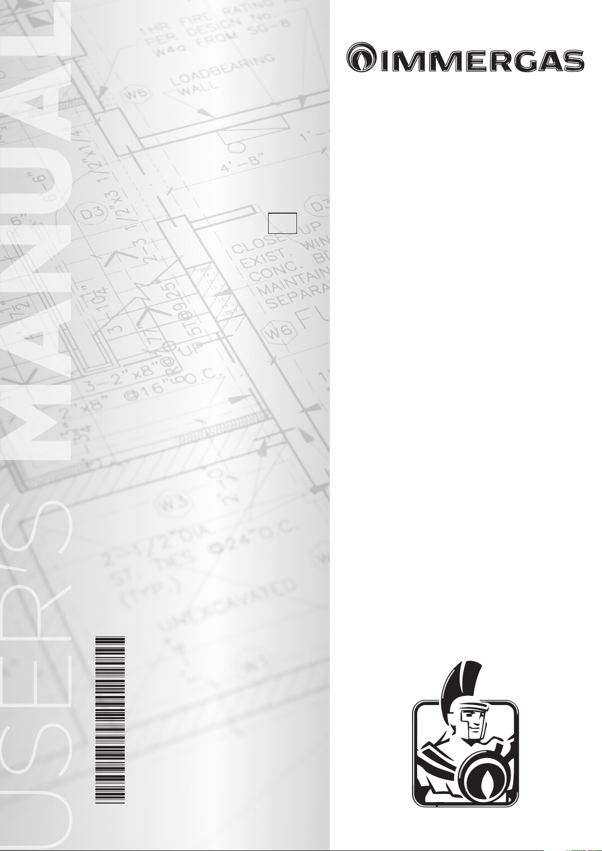
1.2 MAIN DIMENSIONS.
Key:
G - Gas supply
AC - Domestic hot water outlet
ACV - Domestic hot water inlet
solar valve kit (Optional)
AF - Domestic cold water inlet
R - System return
M - System delivery
V - Electric attachment
the warranty.
• Installation regulations:
- these boilers cannot be installed in bedrooms
or shower or bathrooms; ey cannot be installed in rooms with open res without their
own air ow. ey must be installed in rooms
where the temperature cannot fall below 0°C
and must not be exposed to atmospheric
agents.
- Type B open chamber boilers must not be
installed in places where commercial, artisan
or industrial activities take place, which use
products that may develop volatile vapours
or substances (e.g. acid vapours, glues, paints,
solvents, combustibles, etc.), as well as dusts
(e.g. dust deriving from the working of wood,
coal nes, cement, etc.), which may be damaging for the components of the appliance and
jeopardise functioning.
Important: Wall mounting of the boiler must
guarantee stable and ecient support for the
generator.
e plugs (standard supply) are to be used only in
conjunction with the mounting brackets or xing
template to x the appliance to the wall; they only
ensure adequate support if inserted correctly
(according to technical standards) in walls made
of solid or semi-hollow brick or block. In the
case of walls made from hollow brick or block,
partitions with limited static properties, or in any
case walls other than those indicated, a static test
Height
(mm)
751 440 240
GAS
G AC AF R M
3/4” 1/2” 1/2” 3/4” 3/4”
N.B.: connection group (optional)
must be carried out to ensure adequate support.
N.B.: the hex head screws supplied in the blister
pack are to be used exclusively to x the relative
mounting bracket to the wall.
ese boilers are used to heat water to below
boiling temperature in atmospheric pressure.
ey must be connected to a heating system and
hot water circuit suited to their performance
and capacity.
Width
(mm)
ATTACHMENTS
DOMESTIC
HOT WATER
Depth
(mm)
PLANT
1-2
1-1
4
1.3 ATTACHMENTS. Gas connection (Appliance category II
Our boilers are designed to operate with methane
gas (G20) and LPG. Supply pipes must be the
same as or larger than the 3/4”G boiler tting.
Before connecting the gas line, carefully clean
inside all the fuel feed system pipes to remove any
residue that could impair boiler eciency. Also
make sure the gas corresponds to that for which
the boiler is prepared (see boiler data-plate). If
dierent, the appliance must be converted for
operation with the other type of gas (see converting appliance for other gas types). e dynamic
gas supply (methane or LPG) pressure must also
be checked according to the type used in the
boiler, as insucient levels can reduce generator
output and cause malfunctions.
Ensure correct gas cock connection by following
the mounting instructions illustrated in the
figure. The gas supply pipe must be suitably
dimensioned according to current regulations in
order to guarantee correct gas ow to the boiler
even in conditions of maximum generator output
and to guarantee appliance eciency (technical
specications). e coupling system must conform to standards.
Combustible gas quality. The appliance has
been designed to operate with gas free of impurities; otherwise it is advisable to t special
lters upstream from the appliance to restore
the purity of the gas.
Storage tanks (in case of supply from LPG
depot).
- New LPG storage tanks may contain residual
inert gases (nitrogen) that degrade the mixture
delivered to the appliance casing functioning
anomalies.
- Due to the composition of the LPG mixture,
layering of the mixture components may occur
during the period of storage in the tanks. is
can cause a variation in the heating power of
the mixture delivered to the appliance, with
subsequent change in its performance.
Hydraulic attachment.
Important: Before making the boiler connec-
tions, carefully clean the heating system on the
primary heat exchanger (pipes, radiators, etc.)
with special pickling or de-scaling products to
remove any deposits that could compromise
correct boiler operation.
In compliance with Standards in force it is mandatory to treat the water in the heating system
chemically in order to protect the system and
appliance from deposits of lime scale.
Water connections must be made in a rational
way using the couplings on the boiler template.
e boiler safety valve outlet must be connected
to an appropriate drain. Otherwise, the manufacturer declines any responsibility in case of
ooding if the drain valve cuts in.
2H3+
Important: to preserve the duration of appliance
).
eciency features, in the presence of water whose
features can lead to the deposit of lime scale,
installation of the “polyphosphate dispenser” kit
is recommended. On the basis of the Standards in
force, it is mandatory to treat the water with over
25 French degrees in the heating circuit and over
15 French degrees for DHW using conditioning
chemicals for powers < 100 kW or with soeners
for powers > 100 kW.
Electrical connection: e Nike Star 24 3 E
boiler has an IPX4D protection rating for the
entire appliance. Electrical safety of the unit is
reached when it is correctly connected to an
ecient earthing system as specied by current
safety standards.
Important: Immergas S.p.A. declines any
responsibility for damage or physical injury
caused by failure to connect the boiler to an
ecient earth system or failure to comply with
the reference standards.
Also ensure that the electrical installation
corresponds to maximum absorbed power
specications as shown on the boiler data-plate.
e boilers are supplied complete with an “X”
type power cable without plug. e power supply cable must be connected to a 230V ±10% /
50Hz mains supply respecting L-N polarity and
earth connection , this network must also
have a multi-pole circuit breaker with class III
over-voltage category. When replacing the power
supply cable, contact a qualied technician (e.g.
the Immergas Aer-Sales Technical Assistance
Service). e power cable must be laid as shown.
In the event of mains fuse replacement on the
control card, use a 3.15A quick-blow fuse. For
the main power supply to the appliance, never
use adapters, multiple sockets or extension leads.
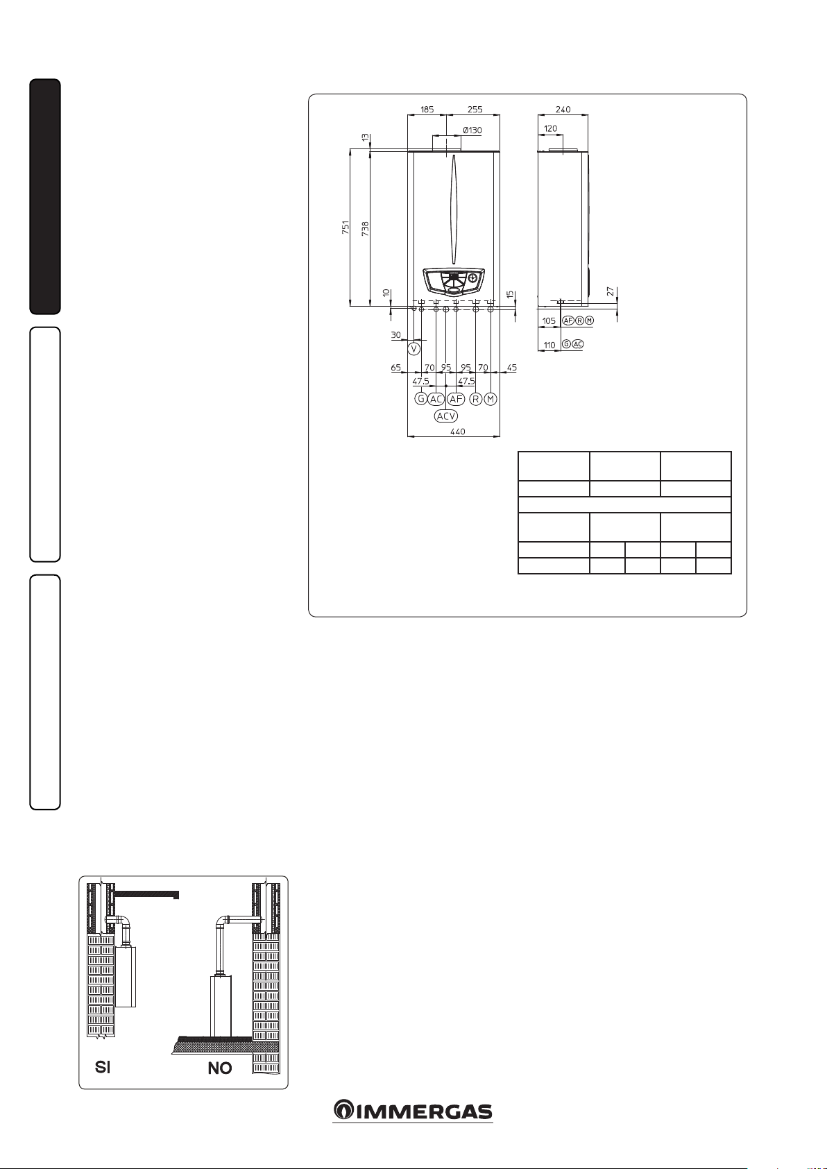
1.4 REMOTE CONTROLS AND
ROOM CHRONOTHERMOSTATS
OPTIONAL.
e boiler is prepared for the application of room
chronothermostats.
ese Immergas components are available as
separate kits to the boiler and are supplied on
request.
All Immergas chronothermostats are connected
with 2 wires only. Carefully read the user and
assembly instructions contained in the accessory kit.
• On/O digital chronothermostat (Fig. 1-3). e
chronothermostat allows:
- to set two room temperature values: one for
day (comfort temperature) and one for night
(lower temperature);
- to set up to four on/o dierential weekly
programs;
- selecting the required function mode from
the various possible alternatives:
• permanent functioning in comfort temp.
• permanent functioning in reduced temp.
• permanent functioning in adjustable antifreeze temp.
e chronothermostat is powered by two 1.5V
LR 6 type alkaline batteries;
• Digital Remote Control Device with climate
chronothermostat function (Fig. 1.4). In addition to the functions described in the previous
point, the Digital Remote Control panel enables
the user to control all the important information regarding operation of the appliance and
the heating system with the opportunity of
easily intervening on the previously set parameters without having to go to the place where
the appliance is installed. e Digital Remote
Control panel is provided with self-diagnosis to
display any boiler functioning anomalies. e
climate chronothermostat incorporated into
the remote panel enables the system delivery
temperature to be adjusted to the actual needs
of the room being heated, in order to obtain
the desired room temperature with extreme
precision and therefore with evident saving
in running costs. e chronothermostat is fed
directly by the boiler by means of the same 2
wires used for the transmission of data between
boiler and chronothermostat.
Digital Remote Control or On/O chronothermostat electrical connections (Optional). e
operations described below must be performed after having removed the voltage from the appliance.
Any thermostat or On/O environment chronothermostat must be connected to clamps 40
and 41 eliminating jumper X40 (Fig. 3-2). Make
sure that the On/O thermostat contact is of the
“clean” type, i.e. independent of the mains supply,
otherwise the electronic adjustment card would
be damaged. e Digital Remote Control must be
connected to clamps 40 e 41 eliminating jumper
X40 on the P.C.B. (in the boiler), (Fig. 3-2).
Important: If the Digital Remote Control is used,
arrange two separate lines in compliance with
current regulations regarding electrical systems.
Boiler pipes must never be used to earth the
electric or telephone lines. Ensure elimination
of this risk before making the boiler electrical
connections.
INSTALLERUSER
MAINTENANCE TECHNICIAN
1-3
1-4
5

1.5 VENTILATION OF THE ROOMS.
In the room in which the boiler is installed it is
necessary that at least as much air ows as that
requested for by normal combustion of the gas
and ventilation of the room. Natural air ow must
take place directly through:
- permanent openings in the walls of the room
to ventilate that lead towards the outside;
- ventilation pipes, individual or branched type.
e air used for ventilation must be withdrawn
directly from outside, in an area away from
INSTALLERUSER
sources of pollution. Natural air flow is also
allowed indirectly by air intake from adjoining
rooms. For further information relative to ventilation of the rooms follow that indicated by the
standards set and the following modications
and integrations.
Evacuation of foul air. In the rooms where the
gas appliances are installed it may also be necessary, as well as the intake of combustion agent air,
to evacuate foul air, with consequent intake of a
further equal amount of clean air. is must be
realised respecting the provisions of the technical
regulations in force.
1.6 FUME DUCTS.
e gas appliances with attachment for the fumes
discharge pipe must have direct connection to
chimneys or safely ecient ues.
Only if these are missing can the combustion
products be discharged directly to the outside,
as long as the standard regulations for the ue
terminal are respected as well as the existing laws.
Connection to chimneys or ues. e connection of the appliances to a chimney or ue takes
place by means of fume ducts.
In the case of connection to pre-existing ues, these
must be perfectly clean as the slag, if present, on detachment from the w alls during functioning, coul d
obstruct the passage of fumes, causing extremely
dangerous situations for the user.
The fume ducts must be connected to the
chimney or ue in the same room in which the
appliance is installed or, at most, in the adjoining
room and must comply with the requisites of
this regulation.
1.7 FLUES/CHIMNEYS.
For the appliances with natural draught individual chimneys and branched ues can be used.
Individual chimneys. e internal dimensions
of some types of individual chimneys are con-
MAINTENANCE TECHNICIAN
tained within the prospects of the regulation. If
the eective system data do not fall within the
conditions of applicability or the table limits, the
size of the chimney must be calculated according
to the regulation.
Branched ues. In buildings with lots of oors, branched ues can be used for the natural
draught evacuation of combustion products
(c.c.r.). New CCR must be designed following
the calculation method and regulation standards.
Chimney caps. e cap is a device positioned
crowning an individual chimney or branched
ue. is device eases the dispersion of combustion products, even in adverse weather conditions, and prevents the deposit of foreign bodies.
is must satisfy the requisites of the regulation.
In order to prevent the formation of counterpressures that impede the discharge of combustion products into the atmosphere, the outlet
height corresponding to the top of the chimney/
ue, independently of any caps, must be over the
“backow area”. It is therefore necessary to use
the minimum heights indicated in the gures
stated in the regulation, depending on the slope
of the roof.
Direct exhaust to the outside. The natural
draught appliances to be connected to a chimney
or a ue can discharge the combustion products
directly to the outside, through a pipe passing
through the perimeter walls of the building. In
this case discharge takes place through an exhaust
ue, which is connected to a draught terminal
at the outside.
Exhaust ue. e exhaust ue must be in compliance with the same requisites listed for the
fume ducts, with further provisions stated in the
regulation in force.
Positioning the dra terminals. e draught
terminals must:
- be installed on external perimeter walls of the
building;
- be positioned according to the minimum distances specied in current technical standards.
Fume exhaust of forced draught appliances in
closed open-top environments. In spaces closed
on all sides with open tops (ventilation pits,
courtyards etc.), direct fume exhaust is allowed
for natural or forced draught gas appliances with
a heating power range from 4 to 35 kW, provided the conditions as per the current technical
standards are respected.
Important: it is prohibited to put the fumes
exhaust control device out of order voluntarily.
Every piece of this device must be replaced using
original spare parts if they have deteriorated. In
the case of repeated interventions of the fumes
exhaust control device, check the fumes exhaust
ue and the ventilation of the room in which the
boiler is located.
1.8 SYSTEM FILLING.
Once the boiler is connected, proceed with system lling via the lling valve (Fig. 2-2). Filling
is performed at low speed to ensure release of air
bubbles in the water via the boiler and heating
system vents. e boiler has a built-in automatic
venting valve on the circulator. Open the radiator
air vent valves. Close radiator vent valves only
when water escapes from them.
Close the lling valve when the boiler manometer
indicates approx. 1.2 bar.
N.B.: during these operations start up the circulation pump at intervals, acting on the main
switch positioned on the control panel. Vent the
circulation pump by loosening the front cap and
keeping the motor running.
Tighten the cap aerwards.
1.9 GAS SYSTEM STARTUP.
To start up the system proceed as follows:
- open windows and doors;
- avoid presence of sparks or naked ames;
- bleed all air from pipelines;
- check that the internal system is properly sealed
according to specications.
6
1.10 BOILER START UP IGNITION.
For issue of the Declaration of Conformity provided for by Italian Law, the following must be
performed for boiler start-up:
- check that the internal system is properly sealed
according to specications;
- ensure that the type of gas used corresponds to
boiler settings;
- switch the boiler on and ensure correct ignition;
- make sure that the gas ow rate and relevant
pressure values comply with those given in the
manual (parag. 3.17);
- check the correct ventilation of the rooms;
- check the existing draught during normal
functioning of the appliance, e.g. a draught
gauge positioned at the exit of the appliance
combustion products;
- check that there is no backow of combustion
products into the room, even during functioning of fans;
- ensure that the safety device is engaged in the
event of gas supply failure and check activation
time;
- check activation of the main switch located
upstream from the boiler.
e boiler must not be started up in the event of
failure to comply with any of the above.
N.B.: the initial check of the boiler must be performed by a qualied technician. e conventional
warranty of the boiler comes into eect from the
date of the check itself. e initial check certicate
and warranty are issued to the user.
1.11 CIRCULATION PUMP.
Nike Star 24 3 E Range boilers are supplied with a
built-in circulation pump with 3-position electric
speed control. e boiler does not operate correctly with the circulation pump on rst speed.
To ensure optimal boiler operation, in the case
of new systems (single pipe and module) it is
recommended to use the circulation pump at
maximum speed. e circulation pump is already
tted with a capacitor.
Pump release. If, aer a prolonged period of
inactivity, the circulation pump is blocked,
unscrew the front cap and turn the motor sha
using a screwdriver. Take great care during this
operation to avoid damage to the motor.
1.12 KITS AVAILABLE ON REQUEST.
• System shut o valves kit. e boiler is designed for installation of system shuto valves to
be placed on delivery and return pipes of the
connection assembly. is kit is particularly
useful for maintenance as it allows the boiler to
be drained separately without having to empty
the entire system.
• Polyphosphate dispenser kit. e polyphosphate dispenser reduces the formation of lime-scale
and preserves the original heat exchange and
domestic hot production water conditions.
e boiler is predisposed for application of the
polyphosphate dispenser kit.
• Connection unit kit. Includes: pipes, ttings
and cocks (including gas cock), to carry out
all connections to the boiler system.
e above-mentioned kits are supplied complete
with instructions for assembly and use.
INSTALLERUSER
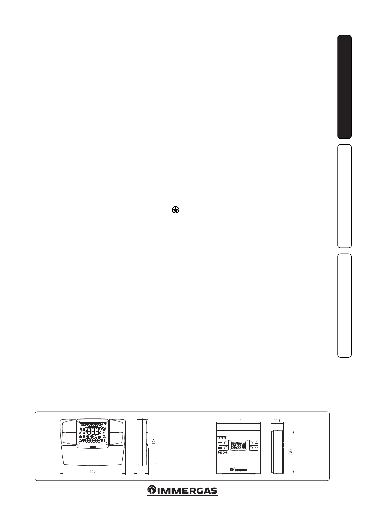
Total head available to the plant.
Head (kPa)
B
D
Flow rate (l/h)
MAINTENANCE TECHNICIAN
A = Head available to the system
at maximum speed with bypass excluded.
B = Head available to the system
at maximum speed with bypass inserted.
O)
2
A
C
7
C = Head available to the system
at second speed with by-pass
excluded.
D = Head available to the system
Head (m H
at second speed with by-pass
inserted.
1-5
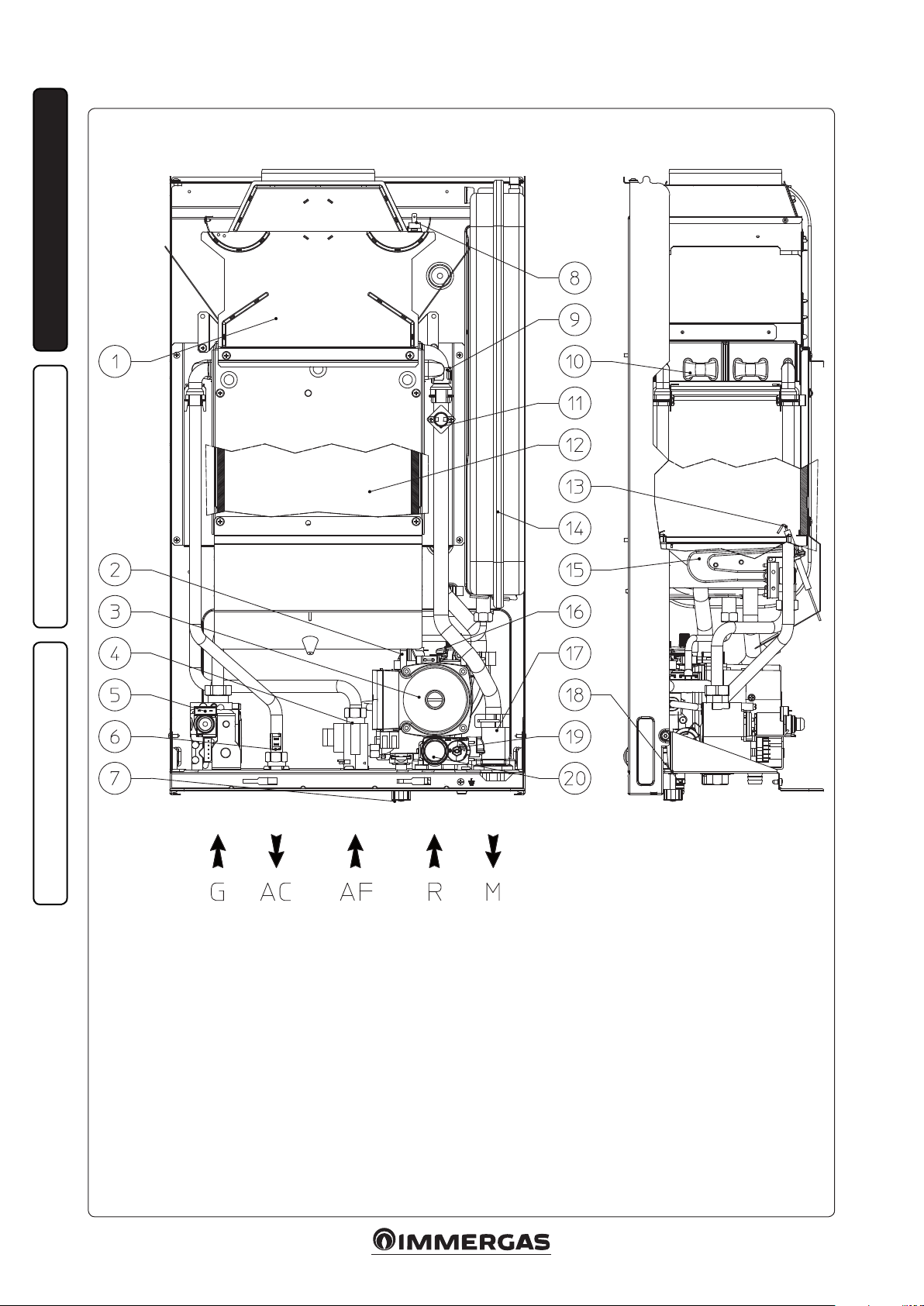
1.13 BOILER COMPONENTS.
INSTALLERUSER
1-33
MAINTENANCE TECHNICIAN
Key:
1 - Fumes hood
2 - System pressure switch
3 - Boiler pump
4 - Domestic hot water ow switch
5 - Gas valve
6 - Domestic hot water probe
7 - System lling valve
8 - Flue safety thermostat
9 - Safety thermostat
10 - Rapid heat exchanger
11 - Delivery probe
12 - Combustion chamber
13 - Ignition and detection electrodes
14 - System expansion vessel
15 - Burner
16 - Vent valve
17 - Manifold
18 - System draining valve
19 - By-pass
20 - 3 bar safety valve
N.B.: connection group (optional)
1-6
8
 Loading...