

Page 1
Instruction and
*1.038789ENG*
warning book
IE
NIKE MYTHOS
24 2 E
Page 2

Dear Customer,
Our compliments for having chosen a top-quality Immergas product, able to assure well-being and safety for a long period of time. As an Immergas customer
you can also count on a qualied aer-sales service, prepared and updated to guarantee constant eciency of your boiler. Read the following pages carefully: you
will be able to draw useful suggestions regarding the correct use of the appliance, the respect of which, will conrm your satisfaction for the Immergas product.
Contact our area authorised aer-sales centre as soon as possible to request commissioning. Our technician will verify the correct functioning conditions; he
will perform the necessary calibrations and will demonstrate the correct use of the generator.
For assistance and scheduled maintenance contact Authorised Immergas Aer-Sales centres: they have original spare parts and are specically trained directly
by the manufacturer.
General recommendations
All Immergas products are protected with suitable transport packaging.
e material must be stored in dry environments protected against bad weather.
e instruction book is an integral and essential part of the product and must be consigned to the new user also in the case of transfer or succession of ownership.
It must be stored with care and consulted carefully, as all of the warnings provide important safety indications for installation, use and maintenance stages.
is instructions manual provides technical information for installing Immergas boilers. As for the other issues related to boiler installation (e.g. safety in the work
site, environment protection, injury prevention), it is necessary to comply with the provisions specied in the regulations in force and principles of good practice.
In compliance with legislation in force, the systems must be designed by qualied professionals, within the dimensional limits established by the Law. Installation
and maintenance must be performed in compliance with the regulations in force, according to the manufacturer's instructions and by professionally qualied
sta, intending sta with specic technical skills in the plant sector, as envisioned by the Law.
Improper installation or assembly of the Immergas appliance and/or components, accessories, kit and devices can cause unexpected problems to people, animals
and objects. Read the instructions provided with the product carefully to ensure a proper installation.
Maintenance must be carried out by skilled technical sta. e Immergas Authorised Aer-sales Service represents a guarantee of qualications and
professionalism.
e appliance must only be destined for the use for which it has been expressly declared. Any other use will be considered improper and therefore potentially
dangerous.
If errors occur during installation, operation and maintenance, due to non compliance with technical laws in force, standards or instructions contained in this
book (or however supplied by the manufacturer), the manufacturer is excluded from any contractual and extra-contractual liability for any damages and the
appliance warranty is invalidated.
For further information regarding legislative and statutory provisions relative to the installation of gas heat generators, consult the Immergas site at the
following address: www.immergas.com
Immergas S.p.A. declines all liability due to printing or transcription errors, reserving the right to make any modications to its technical and commercial
documents without forewarning.
Page 3

INDEX
1 Boiler installation ...................................... 4
1.1 Installation recommendations. ................4
1.2 Main dimensions. ......................................5
1.3 Connections (Optional). .......................... 5
1.4 Remote controls and room chrono-
thermostats (Optional). ............................ 6
1.5 Ventilation of the rooms...........................7
1.6 Flue ducts. .................................................. 7
1.7 Flues/Chimneys. ........................................7
1.8 System lling. ............................................. 7
1.9 Gas system start-up. ..................................7
1.10 Boiler commissioning (ignition). ................8
1.11 Circulation pump. .....................................8
1.12 Kits available on request. .......................... 8
1.13 Boiler components. ...................................9
USER page INSTALLER page MAINTENANCE TECHNICIAN page
2 Instructions for use and maintenance ..10
2.1 Cleaning and maintenance. ...................10
2.2 Ventilation of the rooms.........................10
2.3 General warnings. ................................... 10
2.4 Control panel. ..........................................10
2.5 Troubleshooting. .....................................11
2.6 Restoring central heating system
pressure. .................................................... 11
2.7 System draining. .....................................11
2.8 Anti-freeze protection. ...........................12
2.9 Case cleaning. .......................................... 12
2.10 Decommissioning. ..................................12
3 Boiler commissioning
(initial check) ...........................................13
3.1 Hydraulic diagram. .................................13
3.2 Wiring diagram. ......................................14
3.3 Troubleshooting. .....................................14
3.4 Converting the boiler to other types of
gas. ............................................................. 15
3.5 Checks following conversion to another
type of gas. ................................................ 15
3.6 Possible adjustments. ..............................15
3.7 Programming the P.C.B. .........................15
3.8 Automatic slow ignition function with
timed ramp delivery. ............................... 16
3.9 "Chimney sweep function". ...................16
3.10 Heating Timer. .........................................16
3.11 Pump anti-block function. .....................16
3.12 Radiators anti-freeze function. ..............16
3.13 P.C.B. periodical self-check. ...................16
3.14 Casing removal. .......................................17
3.15 Yearly appliance check
and maintenance. ....................................18
3.16 Variable heat output. ...............................18
3.17 Combustion parameters. ........................19
3.18 Technical data. .........................................19
3.19 Data plate key. ..........................................20
Page 4
BOILER
1
INSTALLATION
1.1 INSTALLATION RECOMMENDATIONS.
e Nike Mythos 24 2E boiler has been designed
for wall mounted installation only, for heating
environments and production of domestic hot
water for domestic use and similar purposes.
e place of installation of the appliance and
relative Immergas accessories must have suitable
features (technical and structural) such to allow
INSTALLERUSER
(always in safety, efficiency and comfortable
conditions):
- installation (according to the provisions of the
technical legislation and technical regulations);
- maintenance operations (including scheduled,
periodic, routine and special maintenance);
- removal (to outdoors in the place for
loading and transporting the appliances
and components) as well as their eventual
replacement with appliances and/or equivalent
components.
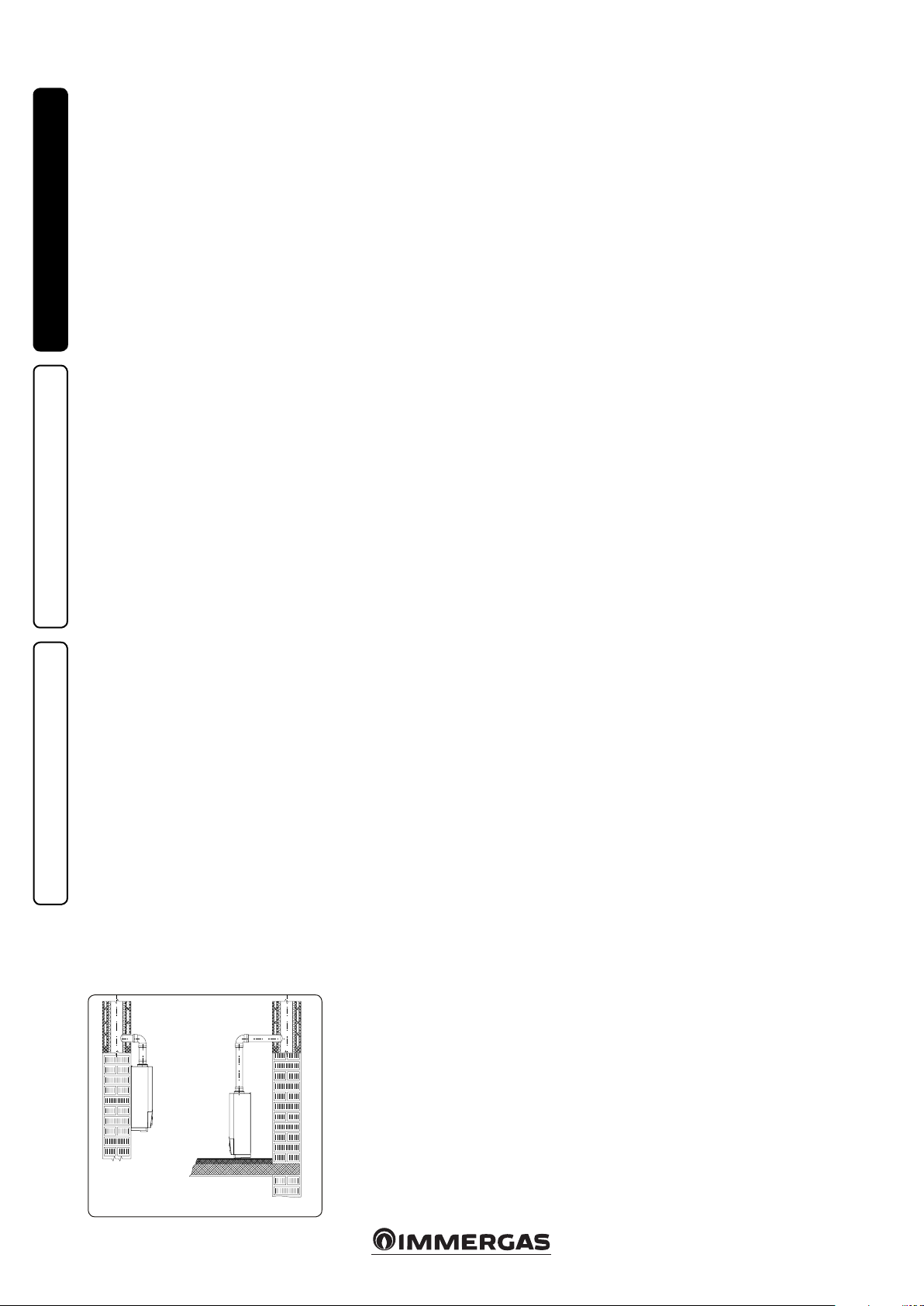
e wall surface must be smooth, without any
protrusions or recesses enabling access to the
rear part. ey are not designed to be installed
on plinths or oors (Fig. 1-1).
Only professionally enabled companies are
authorised to install Immergas gas appliances.
Installation must be carried out according to
regulation standards, current legislation and in
compliance with local technical regulations and
the required technical procedures.
Before installing the appliance, ensure that it
is delivered in perfect condition; if in doubt,
contact the supplier immediately. Packing
materials (staples, nails, plastic bags, polystyrene
foam, etc.) constitute a hazard and must be kept
out of the reach of children. If the appliance
is installed inside or between cabinets, ensure
sucient space for normal servicing; therefore
it is advisable to leave clearance of at least 3
cm between the boiler casing and the vertical
sides of the cabinet. Leave adequate space above
the boiler for possible water and ue removal
connections. It is just as important that the intake
grids are not obstructed. Keep all ammable
objects away from the appliance (paper, rags,
plastic, polystyrene, etc.). Do not place household
appliances underneath the boiler as they could
be damaged if the safety valve intervenes with
an obstructed conveying system (the safety valve
must be conveyed away by a draining funnel), or
MAINTENANCE TECHNICIAN
if there are leaks from the hydraulic connections;
on the contrary, the manufacturer cannot be
held responsible for any damage caused to the
household appliances.
For the aforementioned reasons, we recommend
not placing furnishings, furniture, etc. under
the boiler.
In the event of malfunctions, faults or incorrect
operation, turn the appliance o immediately
and contact an authorised company (e.g. the
Immergas Technical Assistance centre, which
has specically trained sta and original spare
parts). Do not attempt to modify or repair the
appliance alone. Failure to comply with the above
implies personal responsibility and invalidates
the warranty.
• Installation regulations:
- these boilers cannot be installed in bedrooms,
studio ats and bathrooms. ey also cannot
be installed in rooms with wood (or solid
fuel) burning heat generators and in adjacent
and communicating rooms;
- installation in places with a fire risk is
prohibited (for example: garages, closed
parking stalls), gas appliances and relative ue
ducts, ue exhaust pipes and combustion air
intake pipes;
- installation is prohibited on the vertical
projection of cooking hobs;
- installation is also prohibited in places/
environments that constitute common parts
of oce condominiums such as stairs, cellars,
entrance halls, attics, los, escape routes,
etc. if they are not located inside technical
compartments under the responsibility of
each individual building and only accessible
to the user (for the features of the technical
compartments, see the technical standards in
force);
- type B open chamber boilers must not be
installed in places where commercial, artisan
or industrial activities take place, which use
products that may develop volatile vapours
or substances (e.g. acid vapours, glues, paints,
solvents, combustibles, etc.), as well as dusts
(e.g. dust deriving from the working of
wood, coal nes, cement, etc.), which may be
harmful for the components of the appliance
and jeopardise operation;
- they must also be installed in rooms where
the temperature cannot fall below 0°C and
must not be exposed to weathering.
Attention: wall mounting of the boiler must
guarantee stable and ecient support for the
generator.
e plugs (standard supply) are to be used only in
conjunction with the mounting brackets or xing
template to x the appliance to the wall; they only
ensure adequate support if inserted correctly
(according to technical standards) in walls made
of solid or semi-hollow brick or block. In the
case of walls made from hollow brick or block,
partitions with limited static properties, or in any
case walls other than those indicated, a static test
must be carried out to ensure adequate support.
N.B.: the hex head screws supplied in the blister
pack are to be used exclusively to x the relative
mounting bracket to the wall.
ese boilers are used to heat water to below
boiling temperature in atmospheric pressure.
ey must be connected to a central heating
system and hot water circuit suited to their
performance and capacity.
YES NO
Fig. 1-1
4
Page 5
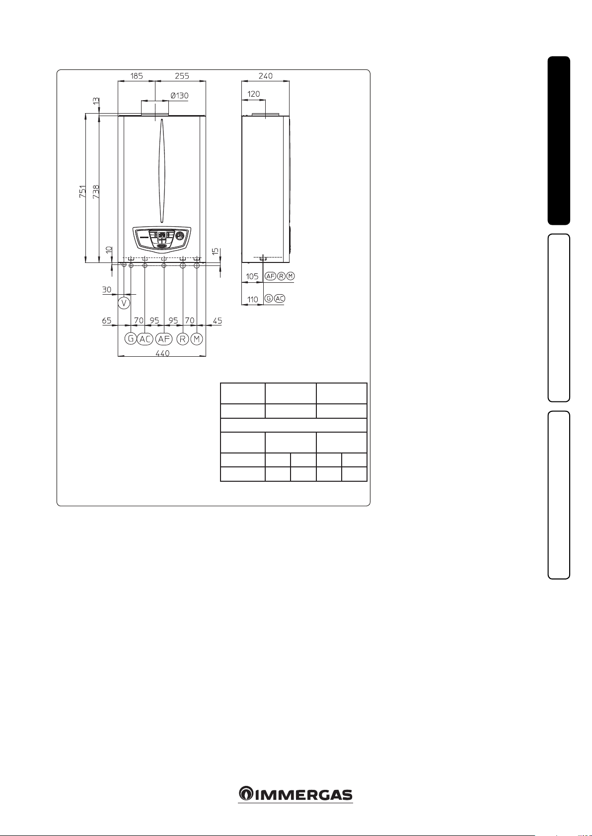
1.2 MAIN DIMENSIONS.
Key:
G - Gas supply
AC - Domestic hot water outlet
AF - Domestic cold water inlet
R - System return
M - System ow
V - Electrical connection
N.B.: connection group (optional)
Fig. 1-2
Height
(mm)
751 440 240
GAS
G AC AF R M
3/4” 1/2” 1/2” 3/4” 3/4”
Width (mm) Depth (mm)
CONNECTIONS
DOMESTIC
WATER
SYSTEM
1.3 CONNECTIONS OPTIONAL.
Gas connection (Appliance category II
Our boilers are designed to operate with methane
gas (G20) or LPG. Supply pipes must be the same
as or larger than the 3/4”G boiler tting. Before
connecting the gas line, carefully clean inside
all the fuel feed system pipes to remove any
residue that could impair boiler eciency. Also
make sure the gas corresponds to that for which
the boiler is prepared (see boiler data-plate).
If dierent, the appliance must be converted
for operation with the other type of gas (see
converting appliance for other gas types). e
dynamic gas supply (methane or LPG) pressure
must also be checked according to the type
used in the boiler, which must comply with the
regulations in force, as insucient levels can
reduce generator output and cause malfunctions.
Ensure correct gas cock connection by following
the mounting instructions illustrated in the
figure. The gas supply pipe must be suitably
dimensioned according to current regulations
in order to guarantee correct gas ow to the
burner even in conditions of maximum generator
output and to guarantee appliance efficiency
(technical specications). e coupling system
must conform to standards.
Fuel gas quality. The appliance has been
designed to operate with combustible gas free of
impurities; otherwise it is advisable to t special
lters upstream of the appliance to restore the
purity of the fuel.
Storage tanks (in case of supply from LPG
depot).
- New LPG storage tanks may contain residual
inert gases (nitrogen) that degrade the mixture
delivered to the appliance casing functioning
anomalies.
- Due to the composition of the LPG mixture,
layering of the mixture components may occur
during the period of storage in the tanks. is
can cause a variation in the heating power of
the mixture delivered to the appliance, with
subsequent change in its performance.
2H3+
).
INSTALLERUSER
MAINTENANCE TECHNICIAN
5
Page 6
Hydraulic connection.
Attention: in order not to void the heat primary
exchanger warranty, before making the boiler
connections, carefully clean the heating system
(pipes, radiators, etc.) with special pickling or
de-scaling products to remove any deposits that
could compromise correct boiler operation.
A chemical treatment of the thermal system
water is required, in compliance with the
technical standards in force, in order to protect
the system and the appliance from deposits (e.g.,
INSTALLERUSER
limescale), slurry or other hazardous deposits.
Water connections must be made in a rational way
using the couplings on the boiler template. e
boiler safety valve outlet must be connected to an
appropriate drain. Otherwise, the manufacturer
declines any responsibility in case of ooding if
the drain valve cuts in.
In order to meet the system requirements
established by the regulations in terms of
pollution of drinking water, we recommend
installing the IMMERGAS anti-backow kit to be
used upstream of the cold water inlet connection
of the boiler. It is also recommended that the heat
transfer uid (e.g. water + glycol) entered in the
primary circuit of the boiler (heating circuit),
complies with the local regulations in force.
Attention: to preserve the duration of appliance
eciency features, in the presence of water whose
features can lead to the deposit of lime scale,
installation of the “polyphosphate dispenser” kit
is recommended.
Electrical connection. e Nike Mythos 24 2E
boiler has an IPX4D protection rating for the
entire appliance. Electrical safety of the appliance
is reached only when it is correctly connected
to an ecient earthing system as specied by
current safety standards.
Attention: Immergas S.p.A. declines any
responsibility for damage or physical injury
caused by failure to connect the boiler to an
ecient earth system or failure to comply with
the reference standards.
Also ensure that the electrical installation
corresponds to maximum absorbed power
specications as shown on the boiler data-plate.
Boilers are supplied complete with an “X” type
power cable without plug. e power supply
cable must be connected to a 230V ±10% / 50Hz
mains supply respecting L-N polarity and earth
MAINTENANCE TECHNICIAN
connection; , this network must also have a
multi-pole circuit breaker with class III overvoltage category.
When replacing the power supply cable, contact a
qualied company (e.g. the Immergas Authorised
Aer-Sales Technical Assistance Service). e
power cable must be laid as shown (Fig. 1-3). In
the event of mains fuse replacement on the P.C.B.,
use a 2A quick-blow fuse. For the main power
supply to the appliance, never use adapters,
multiple sockets or extension leads.
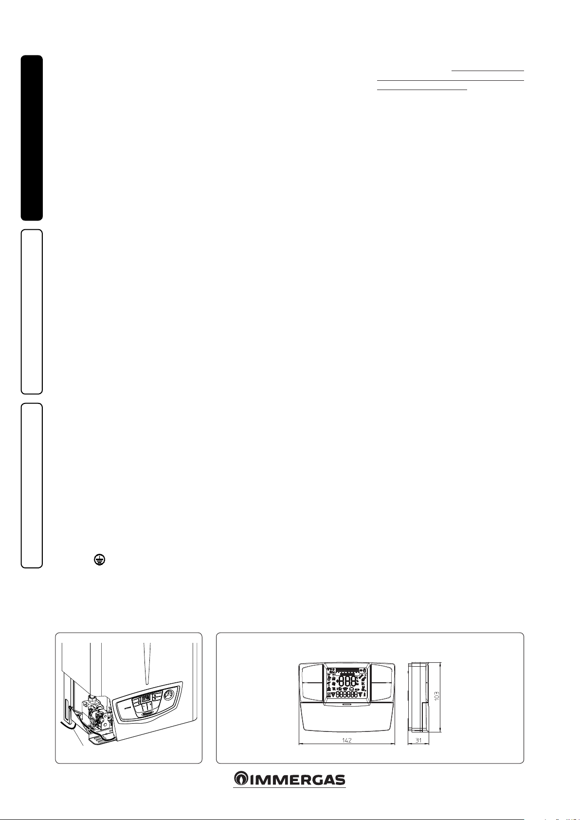
1.4 REMOTE CONTROLS AND
ROOM CHRONOTHERMOSTATS
OPTIONAL.
e boiler is prepared for the application of room
chrono-thermostats or remote controls, which
are available as optional kits. (Fig. 1-4)
All Immergas chrono-thermostats are connected
with 2 wires only. Carefully read the user and
assembly instructions contained in the accessory
kit.
• On/O digital chrono-thermostat. e chrono-
thermostat allows:
- set two room temperature value: one for
daytime (comfort temperature) and one for
nighttime (lower temperature);
- set a weekly programme with four daily
switch on and switch o times;
- select the required operating mode from the
various possible alternatives:
- manual mode (with adjustable temperature);
- automatic mode (with set programme);
- forced automatic mode (momentarily
changing the temperature of the automatic
programme).
e chrono-thermostat is powered by two 1.5V
LR 6 type alkaline batteries.
• Comando Amico Remoto Remote Control
Device V2 (CARV2) with climate chronothermostat function. In addition to the
functions described in the previous point, the
CARV2 panel enables the user to control all the
important information regarding operation
of the appliance and the heating system with
the opportunity to easily intervene on the
previously set parameters, without having
to go to where the appliance is installed.
e panel is provided with self-diagnosis to
display any boiler functioning anomalies.
e climate chrono-thermostat incorporated
into the remote panel enables the system ow
temperature to be adjusted to the actual needs
of the room being heated, in order to obtain
the desired room temperature with extreme
precision and therefore with evident saving in
running costs. e chrono-thermostat is fed
directly by the boiler by means of the same 2
wires used for the transmission of data between
boiler and chrono-thermostat.
CARV2 or chrono-thermostat On/O electric
connection (Optional). e operations described
below must be performed aer having removed
the voltage from the appliance. Any On/O room
chrono-thermostat must be connected to clamps
40 and 41 eliminating jumper X40 (Fig. 3-2).
Make sure that the On/O thermostat contact is
of the “clean” type, i.e. independent of the mains
supply, otherwise the P.C.B. would be damaged.
Any CARV2 must be connected to clamps 40 and
41 eliminating jumper X40 on the circuit board,
paying attention not to invert the polarity in the
connections (Fig. 3-2). 3-2). Connection with
the wrong polarity prevents functioning, but
without damaging the CARV2 e boiler can only
be connected to one remote control.
Important: if the CARV2 remote control is used,
arrange two separate lines in compliance with
current regulations regarding electrical systems.
No boiler pipes must ever be used to earth
the electric system or telephone lines. Ensure
elimination of this risk before making the boiler
electrical connections.
POWER SUPPLY CABLE
CAVO ALIMENTAZIONE
Fig. 1-3
Fig. 1-4
6
Page 7

1.5 VENTILATION OF THE ROOMS.
In the room in which the boiler is installed it is
necessary that at least as much air ows as that
requested for by normal combustion of the gas
and ventilation of the room. Natural air ow must
take place directly through:
- permanent openings in the walls of the room
to be ventilated that lead towards the outside;
- ventilation pipes, individual or branched type.
e air used for ventilation must be withdrawn
directly from outside, in an area away from
sources of pollution. Natural air flow is also
allowed indirectly by air intake from adjoining
rooms. For further information relative to
ventilation of the rooms follow that indicated
by the standards in force and the following
modications and integrations.
Evacuation of foul air. In the rooms where
the gas appliances are installed it may also be
necessary, as well as the intake of combustion
agent air, to evacuate foul air, with consequent
intake of a further equal amount of clean air. is
must be realised respecting the provisions of the
technical regulations in force.
1.6 FLUE DUCTS.
e gas appliances with attachment for the ue
gas discharge pipe must have direct connection
to chimneys or safely ecient ues.
The combustion products can be discharged
directly outside only if these are missing, as long
as the standard regulations for the ue terminal
are respected as well as the existing laws.
Connection to chimneys or flues. The
connection of the appliances to a chimney or
ue takes place by means of ue ducts.
In the event of ttings with pre-existing ues, these
must be perfectly clean because the detachment
of any waste from the walls during functioning,
could block the passage of ue gases, thus causing
extremely dangerous situations for the user.
e ue ducts must be connected to the chimney
or ue in the same room in which the appliance
is installed or, at most, in the adjoining room and
must comply with the requirements indicated by
the regulation.
1.7 FLUES/CHIMNEYS.
For the appliances with natural draught
individual chimneys and branched flues can
be used.
Individual chimneys. e individual ues must
be dimensioned with respect to the standard
in force.
Branched ues. In buildings with lots of oors,
branched flues can be used for the natural
draught evacuation of combustion products. New
ues must be designed following the calculation
method and provisions of the regulation.
Chimney caps. A chimney cap is a device
crowning an individual chimney or collective
branched flue. The device facilitates the
dispersion of combustion products, even with
bad weather, and prevents the deposit of foreign
bodies.
It must meet the standard requirements
e outlet quota, corresponding to the top of the
chimney/ue, independently of any caps, must
be out of the “backow area”, in order to prevent
the formation of counter-pressures that impede
the free discharge of the combustion products
into the atmosphere. It is therefore necessary
to use the minimum heights indicated in the
gures stated in the regulation, depending on
the slope of the roof.
Direct exhaust outside. e natural draught
appliances, envisioned to be connected to a
chimney or a ue, can discharge the combustion
products directly to the outside, through a
pipe passing through the perimeter walls of
the building. In this case discharge takes place
through an exhaust ue, which is connected to
a draught terminal at the outside.
Exhaust flue. The exhaust flue must be in
compliance with the same requisites listed for
the ue ducts, with further provisions stated in
the regulation in force.
Positioning the exhaust terminals. e exhaust
terminals must:
- be installed on external perimeter walls of the
building;
- be positioned according to the minimum
distances specified in current technical
standards.
Fume exhaust of forced draught appliances
in closed open-top environments. In spaces
closed on all sides with open tops (ventilation
pits, courtyards etc.), direct flue gas exhaust
is allowed for natural or forced draught gas
appliances with a heating power range from 4 to
35 kW, provided the conditions as per the current
technical standards are respected.
Important: it is prohibited to put the fumes
exhaust control device out of order voluntarily.
Every piece of this device must be replaced using
original spare parts if they have deteriorated. In
the case of repeated interventions of the fumes
exhaust control device, check the fumes exhaust
ue and the ventilation of the room in which the
boiler is located.
1.8 SYSTEM FILLING.
Once the boiler is connected, proceed with
system filling via the filling valve (Fig. 2-2).
Filling is performed at low speed to ensure
release of air bubbles in the water via the boiler
and heating system vents. e boiler has a builtin automatic venting valve on the circulator.
Open the radiator vent valves. Close radiator
vent valves when only water escapes from them.
Close the lling valve when the boiler manometer
indicates approx. 1.2 bar.
N.B.: during these operations start up the
circulation pump at intervals, acting on the main
switch positioned on the control panel. Vent the
circulation pump by loosening the front cap and
keeping the motor running.
Tighten the cap aer the operation.
1.9 GAS SYSTEM STARTUP.
To start up the system, make reference to the
Standard: is divides the systems and therefore
the start-up operations into three categories: new
systems, modied systems, re-activated systems.
In particular, for new gas systems:
- open windows and doors;
- avoid presence of sparks or open ames;
- bleed all air from the pipelines;
- check that the internal system is properly sealed
according to specications.
INSTALLERUSER
MAINTENANCE TECHNICIAN
7
Page 8

1.10 BOILER COMMISSIONING
IGNITION.
In order to issue the Declaration of Conformity
required by the regulations in force, one must
comply with the following requirements to
commission the boiler (the operations listed
below must only be performed by qualified
personnel and in the presence of sta only):
- check that the internal system is properly sealed
according to the regulations in force;
- make sure that the type of gas used corresponds
to boiler settings;
INSTALLERUSER
- check that there are no external factors that
may cause the formation of fuel pockets;
- switch the boiler on and check correct ignition;
- make sure that the gas ow rate and relevant
pressure values comply with those given in the
manual (par. 3.16);
- check the correct ventilation of the rooms;
- check the existing draught during normal
functioning of the appliance, e.g. a draught
gauge positioned at the exit of the appliance
combustion products;
- check that there is no backow of combustion
products into the room, even during
functioning of fans;
- ensure that the safety device intervenes in the
event of gas supply failure and check the relative
intervention time;
- check activation of the main switch located
upstream of the boiler.
e boiler must not be started up even if only
one of the checks should be negative.
N.B.: the preliminary boiler check must be carried
out by an authorised company. e standard boiler
warranty is valid from the date of inspection.
e test certicate and warranty is issued to the
us er.
1.11 CIRCULATION PUMP.
The Nike Mythos 24 2E series boilers are
supplied with a built-in circulation pump with
three-position electric speed control. e boiler
does not operate correctly with the circulation
pump on rst speed. To ensure optimal boiler
operation, in the case of new systems (single
pipe and module) it is recommended to use the
pump at maximum speed. e circulation pump
is already tted with a capacitor.
Pump release. If, aer a prolonged period of
inactivity, the circulation pump is blocked,
unscrew the front cap and turn the motor sha
using a screwdriver. Take great care during this
operation to avoid damage to the motor.
By-pass regulation (part. 16 Fig. 1-6). If
necessary, the by-pass can be adjusted according
to system requirements from a minimum (bypass excluded) to a maximum (by-pass inserted)
represented by the graph (Fig. 1-5). Make the
adjustment using a at head screwdriver, turn
clockwise and insert the by-pass; by turning it
anti-clockwise it is excluded.
1.12 KITS AVAILABLE ON REQUEST.
• Connection unit kit (on request). The kit
includes pipes, ttings and cocks (including
gas cock), to carry out all connections to the
boiler system
• System shut o valves kit. e boiler is designed
for installation of system interception cocks
to be placed on ow and return pipes of the
connection assembly. is kit is particularly
useful for maintenance as it allows to drain just
the boiler without having to empty the entire
system.
• Polyphosphate dispenser kit. e polyphosphate
dispenser reduces the formation of lime-scale
and preserves the original heat exchange and
domestic hot water production conditions.
e boiler is prepared for application of the
polyphosphate dispenser kit.
e above-mentioned kits are supplied complete
with instructions for assembly and use.
MAINTENANCE TECHNICIAN
Head available to the system.
Head (kPa)
A
B
C
D
Flow rate (l/h)
A = Head available to the system at maximum
speed with by-pass excluded
B = Head available to the system at maximum
speed with by-pass inserted
C = Head available to the system at second
O)
2
Head (m H
speed with by-pass excluded
D = Head available to the system at second
speed with by-pass inserted
Fig. 1-5
8
Page 9

1.13 BOILER COMPONENTS.
INSTALLERUSER
Key:
1 - Fumes hood
2 - System pressure switch
3 - Boiler circulator pump
4 - Domestic hot water ow switch
5 - Gas valve
6 - System lling valve
7 - Flue safety thermostat
8 - Primary heat exchanger
9 - Delivery probe
10 - Safety thermostat
MAINTENANCE TECHNICIAN
11 - Combustion chamber
12 - Ignition and detection electrodes
13 - System expansion vessel
14 - Burner
15 - Vent valve
16 - By-pass
17 - DHW heat exchanger
18 - ree-way valve (motorised)
19 - 3 bar safety valve
20 - System draining valve
N.B.: connection group (optional)
Fig. 1- 6
9
Page 10

INSTRUCTIONS FOR USE
2
AND MAINTENANCE
2.1 CLEANING AND MAINTENANCE. Attention: the heating systems must undergo
periodical maintenance (regarding this, see
the section dedicated to the maintenance
engineer, relating to “yearly appliance check
and maintenance”) and regular energy eciency
checks in compliance with national, regional or
local provisions in force.
is ensures that the optimal safety, per formance
INSTALLERUSER
and operation characteristics of the boiler remain
unchanged over time.
We recommend stipulating a yearly cleaning and
maintenance contract with your zone technician.
2.2 VENTILATION OF THE ROOMS.
In the room in which the boiler is installed it
is necessary that at least as much air ows as
that requested for by normal combustion of the
gas and ventilation of the room. e provisions
relative to ventilation, the ue ducts, chimneys
and caps are stated in Par. 1.5, 1.6 and 1.7. If
in doubt regarding correct ventilation, refer to
professional, qualied sta..
2.3 GENERAL WARNINGS.
Never expose the wall-mounted boiler to direct
vapours from a cooking surface.
Use of the boiler by unskilled persons or children
is strictly prohibited.
If temporary shutdown of the boiler is required,
proceed as follows:
a) drain the heating system if anti-freeze is not
used;
b) shut-o all electrical, water and gas supplies.
In the case of work or maintenance to structures
located in the vicinity of ducting or devices
for flue extraction and relative accessories,
switch o the appliance and on completion of
operations ensure that a qualied technician
checks eciency of the ducting or other devices.
Never clean the appliance or connected parts
with easily ammable substances.
Never leave containers or ammable substances
in the same environment as the appliance.
It is prohibited and dangerous to obstruct the air
intake, even partially, for the ventilation of the
room in which the boiler is installed.
Due to the danger, functioning is also prohibited
in the same room as suction devices, chimneys
or similar at the same time as the boiler unless
there are additional openings dimensioned in a
way to satisfy the further necessity for air. For the
dimensioning of these additional openings, refer
to qualied technical sta. In particular, an open
re must have its own air supply.
On the contrary, the boiler cannot be installed
in the same room.
• Attenzione: the use of components involving
use of electrical power requires some
fundamental rules to be observed:
- do not touch the appliance with wet or
moist parts of the body; do not touch when
barefoot;
- never pull electrical cables or leave the
appliance exposed to weathering (rain,
sunlight, etc.);
- the appliance power cable must not be
replaced by the user;
- in the event of damage to the cable, switch
off the appliance and contact exclusively
qualied sta for replacement;
- if the appliance is not to be used for a certain
period, disconnect the main power switch.
2.4 CONTROL PANEL.
Fig. 2-1
MAINTENANCE TECHNICIAN
Key:
1 - Reset button
2 - Stand-by/summer/winter button
3 - Button (+) to increase
the domestic hot water temperature
4 - Button (-) to reduce
the domestic hot water temperature
5 - Button(+) to increase the system water
temperature
6 - Button (-) to reduce the system water
temperature
7 - Boiler manometer
8 - Domestic hot water functioning
9 - Temperatures and error code display
10 - Unit of measurement
11 - Central heating functioning
12 - Winter
13 - Summer
14 - Power distributed
15 - Flame presence
10
Page 11

Boiler ignition. Before ignition make sure the
heating system is lled with water and that the
manometer (7) indicates a pressure of 1 ÷ 1.2 bar.
- Open the gas cock upstream from the boiler.
- Press key (2) and set the boiler on Summer (
) or Winter ( ).
N.B.: the button (2) must be pressed and
held for the time required to switch from the
Stand-by ( ), Summer ( ) or Winter ( )
function.
Attention: aer each switch the button must
in any case be released to switch to the next
function.
When in summer position ( ) the domestic
hot water temperature is adjusted with the buttons (3-4).
When the winter position is selected ( ) the
system water temperature is adjusted with the
buttons (5-6), whilst the domestic hot water
temperature is adjusted using the buttons (3-4),
by pressing (+) to increase and (-) to reduce the
temperature.
From this moment the boiler functions automatically. With no demand for heat (heating or
domestic hot water production) the boiler goes
to “standby” function, equivalent to the boiler
being powered without presence of ame. Each
time the boiler ignites, the relative ame present
symbol is displayed (15).
2.5 TROUBLESHOOTING.
In the event of an anomaly the boiler backlight
turns from green to red on and the relative error
codes, listed in the table, ash on the display.
Anomaly signalled
No ignition block 01
Over-heating (safety) thermostat
block
Flue safety thermostat anomaly 03
Electro-mechanical contacts 04
Flow probe anomaly 05
Insucient system pressure 10
Parasite ame 20
Insucient circulation 27
Loss of remote control commu-
nication
Ignition block. e boiler ignites automatically
with each request for room heating or hot water
production. If the burner does not ignite within
10 seconds, the boiler goes into "ignition block"
(code 01). To eliminate “ignition block” the Reset
button (1) must be pressed. On commissioning
or aer extended appliance downtime, it may
be necessary to eliminate the “ignition block”. If
this phenomenon occurs frequently, contact an
authorised company (e.g. Immergas Aer-Sales
Technical Assistance Service).
code
error
02
31
Overheating thermostat block. During normal
operation, if a fault causes excessive overheating
internally, the boiler goes into overheating block
(code 02). Aer allowing to cool, eliminate the
"overheating block" by pressing the Reset key (1).
If this phenomenon occurs frequently, contact an
authorised company (e.g. Immergas Aer-Sales
Technical Assistance Service).
Flue safety thermostat anomaly. If the flue
evacuation pipe does not work properly during
functioning, the ue thermostat intervenes by
blocking the boiler (code 03). The boiler will
automatically restart aer 30 minutes if normal
conditions resume without having to be reset.
If the ue thermostat intervenes 3 times in less
than two hours (code 03), it is necessary to reset
the boiler manually by pressing the Reset button
(1). If this anomaly persists, contact a qualied
technician for assistance (e.g. Immergas AerSales Service).
Electro-mechanical contacts is occurs when
the safety thermostat, the fume pressure switch or
the system pressure switch do not work properly
(code 04). e boiler does not start; try resetting
the boiler. If the anomaly persists contact an
authorised company (e.g. Immergas Aer-Sales
Technical Assistance Service).
Delivery probe anomaly If the board detects an
anomaly on the ow probe (code 05), the boiler
will not start; contact an authorised company
(e.g. Immergas Aer-Sales Technical Assistance
Service).
Insucient system pressure. Water pressure
inside the heating system (code 10), sucient to
guarantee the correct functioning of the boiler,
is not detected. Check that the system pressure
is between 1÷1.2 bar.
Parasite ame. is occurs in the event of a leak
on the detection circuit or anomaly in the ame
control unit (code 20); try to reset the boiler.
If the anomaly persists contact an authorised
company (e.g. Immergas Aer-Sales Technical
Assistance Service).
Insucient water circulation. is occurs if
the boiler overheats due to insucient water
circulating in the primary circuit (code 27); the
causes can be:
- low system circulation; check that no shut-o
devices are closed on the heating circuit and
that the system is free of air (deaerated);
- pump blocked; free the pump.
If this phenomenon occurs frequently, contact an
authorised company (e.g. Immergas Aer-Sales
Technical Assistance Service).
Loss of Remote Control communication. is
occurs 1 minute aer loss of communication
between the boiler and the remote control (code
31). To reset the error code, remove and re-apply
voltage to the boiler. If this phenomenon occurs
frequently, contact an authorised company (e.g.
Immergas After-Sales Technical Assistance
Service).
Boiler shutdown. Press the button (2 Fig. 2-1)
( ) until the symbol ( ) appears on the
di splay.
N.B.: in these conditions the boiler is still
powered.
Disconnect the external omnipolar boiler switch
and close the gas cock upstream of the appliance.
Never leave the boiler switched on if le unused
for prolonged periods.
2.6 RESTORING CENTRAL HEATING SYSTEM PRESSURE.
Periodically check the system water pressure.
e boiler manometer should read a pressure
between 1 and 1.2 bar.
If the pressure is below 1 bar (with the circuit cool)
restore normal pressure via the lling cock located
in the lower part of the boiler (Fig. 2-2).
N.B.: close the lling cock aer the operation.
If pressure values reach around 3 bar the safety
valve may be activated.
In this case contact a professional technician
for assistance.
In the event of frequent pressure drops, contact
qualied sta for assistance to eliminate the possible system leakage.
2.7 SYSTEM DRAINING.
To drain the boiler, use the special draining
valve (Fig. 2-2).
Before draining, ensure that the lling valve is
closed.
INSTALLERUSER
MAINTENANCE TECHNICIAN
11
Page 12

2.8 ANTIFREEZE PROTECTION.
e boiler features an antifreeze function that
automatically ignites the burner when the temperature falls below 4°C and stops once 42°C
have been exceeded. e antifreeze function is
ensured if the appliance is in perfect working
order in all its parts, if it is not “blocked”, and if it
is not in “o ” mode. To avoid keeping the system
switched on in case of a prolonged absence, the
system must be drained completely or antifreeze
substances must be added to the heating system
water. In both cases the boiler domestic hot wa-
INSTALLERUSER
ter circuit must be drained. In systems that are
drained frequently, lling must be carried out
with suitably treated water to eliminate hardness
that can cause lime-scale.
2.9 CASE CLEANING.
Use damp cloths and neutral detergent to clean
the boiler casing. Never use abrasive or powder
detergents.
2.10 DECOMMISSIONING.
In the event of permanent shutdown of the boiler,
contact professional sta for the procedures and
ensure that the electrical, water and gas supply
lines are shut o and disconnected.
MAINTENANCE TECHNICIAN
Bottom view.
Key:
1 - Filling valve
2 - Draining valve
Fig. 2-2
12
Page 13

BOILER COMMISSIONING
3
INITIAL CHECK
To commission the boiler:
- make sure that the declaration of conformity
for installation is supplied with the appliance;
- make sure that the type of gas used corresponds
to boiler settings;
- check connection to a 230V-50Hz power
mains, correct L-N polarity and the earthing
connection;
- make sure the central heating system is lled
with water and that the manometer indicates
a pressure of 1÷1.2 bar.
- switch the boiler on and check correct ignition;
3.1 HYDRAULIC DIAGRAM.
- make sure the gas maximum, intermediate
and minimum ow rate and pressure values
correspond to those given in the handbook
par. 3.16;
- check activation of the safety device in the event
of no gas, as well as the relative activation time;
- check activation of the main switch located
upstream of the boiler;
- check the existing draught during normal
functioning of the appliance, e.g. a draught
gauge positioned at the exit of the appliance
combustion products;
- check that there is no backow of combustion
products into the room, even during
functioning of fans;
- ensure activation of all adjustment devices;
- seal the gas ow rate regulation devices (if
settings are modied);
- check the production of domestic hot water;
- check sealing eciency of water circuits;
- check ventilation and/or aeration of the
installation room where required.
If even only a single safety check oers a negative
result, do not commission the system.
INSTALLERUSER
Key:
1 - Domestic hot water ow switch
2 - System lling valve
3 - Flow limiter
4 - Gas valve
5 - System expansion vessel
6 - Burner
7 - Primary heat exchanger
8 - Fumes hood
9 - Flue safety thermostat
10 - Safety thermostat
11 - Delivery probe
12 - Vent valve
13 - Boiler circulator pump
14 - System draining valve
15 - System pressure switch
16 - DHW heat exchanger
17 - ree-way valve (motorised)
18 - By-pass
19 - 3 bar safety valve
G - Gas supply
AC - Domestic hot water outlet
AF - Domestic cold water inlet
R - System return
M - System ow
MAINTENANCE TECHNICIAN
13
Fig. 3-1
Page 14

3.2 WIRING DIAGRAM.
3
INSTALLERUSER
546
Key:
B1 - Flow probe
CARV2- Comando Amico Remoto remote
control Version 2 (optional)
DS1 - Display
E3 - Ignition and
detection electrode
E4 - Safety thermostat
E6 - Flue safety thermostat
F1 - Phase fuse
F2 - Neutral fuse
10
8
7
5
4
5
4
7
2
M1 - Boiler circulator pump
M30 - ree-way valve
S2 - Operation selector
S3 - Block reset button
S4 - Domestic hot water ow switch
S5 - System pressure switch
S20 - Room thermostat (optional)
S21 - Domestic hot water temperature
increase button
S22 - Domestic hot water temperature
decrease button
7
4
7
8
7
8
9
998
9
5
S23 - Heating temperature increase
button
S24 - Heating temperature decrease
button
T1 - Low voltage power supply unit
T2 - Ignition transformer
U1 - Rectier inside the gas valve
connector (only available on
Honeywell gas valves)
1
X40 - Room thermostat jumper
Y1 - Gas valve
Y2 - Gas valve modulator
1 - User interface
2 - N.B.: the user interface is on the
welding side of the boiler board
3 - Power supply 230Vac 50Hz
4 - Blue
5 - Brown
6 - Yellow/Green
7 - Black
8 - Grey
9 - White
10 - e x6 connector is used for
automatic inspection
Fig. 3-2
Comando Amico RemotoV2: the boiler is setup for the application of the Comando Amico
Remoto remote control V2 (CARV2) which must
be connected to clamps 40 and 41, by observing
polarity and eliminating jumper X40.
MAINTENANCE TECHNICIAN
Room thermostat: the boiler is set-up for the
application of the Room ermostat (S20) which
must be connected to clamps 40 and 41 and by
eliminating jumper X40.
e connector X6 is for connection to a personal
computer.
3.3 TROUBLESHOOTING. N.B.: maintenance interventions must be carried
out by an authorised company (e.g. Immergas
Aer-Sales Technical Assistance Service).
- Smell of gas. Caused by leakage from gas circuit
pipelines. Check sealing eciency of gas intake
circuit.
- Irregular combustion (red or yellow ame).
When the burner is dirty or the boiler lamellar
pack is blocked. Clean the burner or the boiler
lamellar pack.
- Frequent interventions of the over heating
safety thermostat. It can depend on the lack
of water in the boiler, little water circulation
in the system or blocked pump. Check on the
manometer that the system pressure is within
established limits. Check that the radiator
valves are not closed and also the functionality
of the pump.
- e boiler produces condensate. is can be
caused by obstructions of the chimney or ues
with height or section not proportioned to the
boiler. It can also be determined by functioning
at boiler temperatures that are excessively low.
In this case, make the boiler run at higher
temperatures.
- Frequent interventions of the flue safety
thermostat. is can be caused by obstructions
in the fumes circuit. Check the ue. e ue
may be obstructed or by height or section
not suitable for the boiler. Ventilation may be
insucient (see room ventilation point).
- Presence of air in the system. Check opening of
the special air vent valve cap (Fig. 1-6). Make
sure the system pressure and expansion vessel
pressure values are within the set limits; the
pressure value for the expansion vessel must be
1.0 bar, and system pressure must be between
1 and 1.2 bar.
- Ignition block and Chimney block. (See par.
2.5 and 1.3 (electric connection).
14
Page 15

3.4 CONVERTING THE BOILER TO OTHER TYPES OF GAS.
If the boiler has to be converted to a dierent gas
type to that specied on the data plate, request
the relative conversion kit for quick and easy
conversion.
e gas conversion operation must be carried
out by an authorised company (e.g. Immergas
Aer-Sales Technical Assistance Service).
To convert to another type of gas the following
operations are required:
- disconnect the appliance;
- replace the main burner injectors, making sure
to insert the special seal rings supplied in the
kit, between the gas manifold and the injectors;
- re-power the appliance;
- select, using the boiler key, the gas parameter
type (P1) and select (nG) in the case of methane
supply or (LG) in the case of LPG supply;
- adjust the boiler nominal heat output;
- adjust the boiler nominal heat output in
domestic hot water phase;
- adjust the boiler nominal heat output in heating
phase;
- adjust (eventually) the maximum heating
power;
- seal the gas ow rate regulation devices (if
settings are modied);
- after completing the conversion, apply the
sticker, contained in the conversion kit, near
the data-plate. Using an indelible marker pen,
cancel the data relative to the old type of gas.
ese adjustments must be made with reference
to the type of gas used, following that given in
the table (Par. 3.16).
3.5 CHECKS FOLLOWING CONVERSION TO ANOTHER TYPE OF GAS.
Aer making sure that conversion was carried
out with a nozzle of suitable diameter for the
type of gas used and the settings are made at the
correct pressure, check that:
- there is no ame in the combustion chamber;
- the burner ame is not too high or low and that
it is stable (does not detach from burner);
- the pressure testers used for calibration are
perfectly closed and there are no leaks from
the gas circuit.
N.B.: all boiler adjustment operations must
be carried out by an authorised company (e.g.
Immergas After-Sales Assistance). Burner
adjustment must be carried out using a
dierential "U" or digital type pressure gauge
connected to the gas valve outlet pressure point
(part. 4 Fig. 3-3), keeping to the pressure value
given in the table (Par. 3.16) according to the type
of gas for which the boiler is prepared.
3.6 POSSIBLE ADJUSTMENTS.
• Adjustment of boiler nominal thermal heat
output.
- Press the domestic hot water adjustment button
(+) (3 Fig. 2-1) up to the maximum operating
temperature.
- Open the domestic hot water cock in order to
prevent modulation intervention.
- With the brass nut (3 Fig. 3-3) adjust the boiler
nominal output, observing the maximum
pressure values stated in the tables (Par. 3.16)
depending on the type of gas.
- By turning in a clockwise direction the heating
potential increases and in an anti-clockwise
direction it decreases.
• Adjust the boiler minimum heat output in the
domestic hot water phase (Fig. 3-3).
N.B.: only proceed aer having calibrated the
nominal pressure.
Adjustment of the minimum thermal input
is obtained by operating on the cross plastic
screws (2) on the gas valve maintaining the
brass nut blocked (3);
- disconnect the power supply to the modulating
coil (just disconnect a faston); by turning
the screw clockwise, the pressure increases,
anti-clockwise it decreases. On completion of
calibration, re-apply the power supply to the
modulating coil. e pressure to which the
boiler minimum power must be adjusted, must
not be lower than that stated in the tables (Par.
3.16) depending on the type of gas.
N.B.: to adjust the gas valve, remove the plastic
cap (6); aer adjusting, ret the cap.
3.7 PROGRAMMING THE P.C.B.
e boiler is prepared for possible programming of
several operation parameters. By modifying these
parameters as described below, the boiler can be
adapted according to specic needs.
To access the programming phase, proceed as
follows (references Fig. 2-1):
- press buttons (1) and (2) for 15 about seconds
until the programming mode is accessed on
the display;
- using buttons (3) and (4), select the parameter
to be changed indicated in the following table:
List of
param-
eters
P1 Gas type selection
Special gas G110 selection (Not
P2
used on this model)
Fixed or correlated domestic
P3
hot water set-point
P5 Minimum CH output
Description
- adjust the corresponding value consulting the
table using keys (5) and (6);
- conrm the set value pressing the reset key
(1) for approximately 5 seconds; pressing keys
(3) + and (4) - at the same time to adjust the
domestic hot water temperature, the operation
is cancelled.
N.B.: aer a period of time, without touching
any keys, the operation cancels automatically.
Gas type selection. e setting of this function
is used to adjust the boiler in order to function
with LPG gas or Methane gas.
Gas type selection
Range of values which can
be set
LG (LPG) o nG (Methane) P1
Gas G110 - Industrial gas (Not used on this
model). e setting of this function is used to
adjust the boiler in order to function with gases
from the rst family.
Gas G110 - Industrial gas (rst family gas)
Range of values which can
be set
on - o (Standard setting) P2
Fixed or correlated domestic hot water setpoint. By setting the parameter P3 in on mode,
burner disabling is correlated to the adjustment
of the domestic hot water temperature. In OFF
mode, the burner is switched o at maximum
value.
Fixed or correlated domestic hot water
set-point
Range of values which can
be set
on correlated - o xed (Stand-
ard settings)
Parameter
Parameter
Parameter
P3
INSTALLERUSER
MAINTENANCE TECHNICIAN
P6 Maximum CH output
P7 Central heating ignitions timer
P8 Central heating ramp timer
Boiler type (monothermal -
P9
bithermal)
15
Page 16

SIT 845 GAS Valve
Key:
1 - Coil
2 - Minimum power
adjustment screw
3 - Maximum power
adjustment nut
4 - Gas valve outlet pres-
sure point
5 - Gas valve inlet pres-
INSTALLERUSER
Heating output. e boiler also has electronic
modulation that adapts the boiler potentiality
to the eective heating demand of the house.
en the boiler works normally in a variable
gas pressure eld between the minimum heating
output and the maximum heating output
depending on the system's heating load.
N.B.: the boiler is produced and calibrated in
the central heating phase at nominal output.
Approximately 10 minutes are needed to reach
the nominal heat output changeable using
parameter (P6).
N.B.: the selection of the “Minimum heating
output” and “Maximum heating output”
parameters, in presence of a heating request,
allows boiler ignition and power supply of the
modulator with current equal to the value of the
respective set value.
MAINTENANCE TECHNICIAN
Timer setting. The boiler has an electronic
timing device that prevents the burner from
igniting too oen in the heating phase. e boiler
is supplied as per standard with a timer adjusted
at 3 minutes.
sure point
6 - Protection hood
Fig. 3-3
Minimum CH output
Range of values which can
be set
from 0 % Imax. to 63 % Imax. P5
Maximum CH output
Range of values which can
be set
from 0 % Imax. to 99 % Imax.
(Standard setting)
4
1
5
Parameter
Parameter
P6
3
2
6
Central heating ramp timing. The boiler
performs an ignition ramp of about 10 minutes
to arrive from minimum power to nominal
heating power.
Central heating ramp timer
Range of values which can
be set
from 1 to 10
10 = 10 minutes (Standard
setting)
1 = 30 seconds
Boiler type. By selecting this parameter one
can select the operation of the type of boiler
being used: instantaneous monothermal boiler
(0), bithermal boiler (1) or monothermal with
boiler (2).
N.B.: according to the selection, also move the
jumper (JP1) on the circuit board (Fig. 3-2):
position 1-2 for bithermal boiler or position 2-3
for monothermal boiler.
Attention: the boiler is already adjusted when
it leaves the factory, therefore this function is
only to be used in the event the circuit board
is replaced.
Boiler type
Range of values which can
be set
from 0 to 2
0 = monothermal boiler (instantaneous)
1 = bithermal boiler
2 = monothermal boiler (with
boiler)
Parameter
P8
Parameter
P9
3.9 "CHIMNEY SWEEP FUNCTION".
When activated, this function forces the boiler
at max. output for 15 minutes.
In this state all adjustments are excluded and
only the temperature safety thermostat and the
limit thermostat remain active. To activate the
chimney sweep function, press the Reset key
for at least 10 seconds. Its activation is indicated
by the flashing symbols (8 and 11 Fig. 2-1).
is function allows the technician to check
the combustion parameters. Aer the checks
disable the function, switching the boiler o and
then on again or simply by pressing the button
(2 Fig. 2-1).
3.10 HEATING TIMER.
e boiler has an electronic timing device that
prevents the burner from igniting too oen in
the heating phase. e boiler is supplied as per
standard with a timer adjusted at 3 minutes. To
adjust the timer values, follow instructions for
parameter settings by selecting parameter (P7)
and set it with one of the values indicated on the
relative table.
3.11 PUMP ANTIBLOCK FUNCTION.
In the “summer” functioning mode ( ) the
boiler has a function that starts the pump at least
once every 24 hours for 30 seconds in order to
reduce the risk of the pump becoming blocked
due to prolonged inactivity.
In the “winter” functioning mode ( ) the boiler
has a function that makes the pump start at least
once every 3 hours for 30 seconds.
3.12 RADIATORS ANTIFREEZE
FUNCTION.
If the system return water is below 4°C, the boiler
starts up until reaching 42°C.
3.13 P.C.B. PERIODICAL SELFCHECK.
During functioning in heating mode or with
boiler in standby, the function activates every 18
hours aer the last boiler check/power supply. In
case of functioning in domestic hot water mode
the self-check starts within 10 minutes aer the
end of the withdrawing in progress, for duration
of approx. 10 seconds.
N.B.: during self-check, the boiler remains o,
including signalling.
Central heating ignitions timer
Range of values which can
be set
from 1 to 10
3 = 3 minutes (Standard setting)
1 = 30 seconds
Parameter
P7
3.8 AUTOMATIC SLOW IGNITION FUNCTION WITH TIMED RAMP DELIVERY.
In the ignition phase the P.C.B. carries out an
increasing gas delivery ramp (with pressure
values that depend on the type of gas selected)
with preset duration. This prevents every
calibration or precision adjustment of the boiler
ignition phase in any conditions of use.
16
Page 17

3.14 CASING REMOVAL.
To facilitate boiler maintenance the casing can be
completely removed as follows (Fig. 3-4):
- remove the frame (1) holding the edges and
pulling it towards you as indicated by the
arrows;
- undo the 2 front screws (2) and the 2 lower
screws (3) which fasten the casing (4);
- pull the casing (4) towards yourself and
upwards at the same time in order to detach it
from the upper hooks.
INSTALLERUSER
4
2
MAINTENANCE TECHNICIAN
2
3
3
1
Fig. 3-4
17
Page 18

3.15 YEARLY APPLIANCE CHECK AND MAINTENANCE.
e following checks and maintenance should
be performed at least once a year.
- Clean the ue side of the heat exchanger.
- Clean the main burner.
- Visually check the draught-breaker/anti-wind
device for deterioration or corrosion.
- Check ignition and operation.
- Check correct calibration of the burner in
domestic hot water and central heating phases.
INSTALLERUSER
- Check the operation of the appliance control
and adjustment devices and in particular:
- intervention of main electrical switch
positioned outside of the boiler;
- system control thermostat intervention;
- domestic hot water control thermostat
intervention.
- Check sealing eciency of the gas circuit and
the internal system.
- Check the intervention of the device against no
gas ionisation ame control. Intervention time
must be less than 10 seconds.
- Visually check for water leaks or oxidation
from/on connections.
- Visually check that the water safety drain valves
is not blocked.
- Check that, aer discharging system pressure
and bringing it to zero (read on boiler pressure
gauge), the expansion vessel load is at 1.0 bar.
- Check that the system static pressure (with
system cold and aer relling the system by
means of the lling valve) is between 1 and 1.2
bar.
- Visually check that the safety and control
devices have not been tampered with and/or
shorted, in particular:
- temperature safety thermostat;
- water pressure switch,
- ue exhaust control thermostat.
- Check the condition and integrity of the
electrical system and in particular:
- electrical power cables must be inside the
fairleads;
- there must be no traces of blackening or
burning.
N.B.: when performing periodical maintenance
of the appliance it is also good practice to
check and perform maintenance on the heating
system, in compliance with that indicated by the
regulations in force.
3.16 VARIABLE HEAT OUTPUT.
METHANE (G20) BUTANE (G30) PROPANE (G31)
THERMAL
POWER
THERMAL
POWER
BURNER GAS
FLOW RATE
PRESS. BURNER
NOZZLES
BURNER GAS
FLOW RATE
PRESS. BURNER
NOZZLES
BURNER GAS
FLOW RATE
(kW) (kcal/h) (m3/h) (mbar) (mm H2O) (kg/h) (mbar) (mm H2O) (kg/h) (mbar) (mm H2O)
23.6 20296 2.78 12.60 128.5 2.08 26.60 271.3 2.04 34.90 355.9
23.0 19780 2.71 11.99 122.2 2.02 25.67 261.8 1.99 33.24 339.0
22.0 18920 2.59 11.01 112.3 1.94 24.15 246.3 1.90 30.59 312.0
21.0 18060 2.48 10.08 102.8 1.85 22.66 231.1 1.82 28.07 286.3
20.0 17200 2.36 9.21 93.9 1.76 21.19 216.1 1.73 25.68 261.9
MAINTENANCE TECHNICIAN
19.0 16340 2.25 8.38 85.4 1.68 19.75 201.3 1.65 23.40 238.7
18.0 15480 2.13 7.59 77.4 1.59 18.32 186.8 1.56 21.24 216.6
17.0 14620 2.02 6.85 69.8 1.51 16.91 172.4 1.48 19.19 195.7
16.0 13760 1.90 6.14 62.6 1.42 15.52 158.2 1.40 17.24 175.8
CH
+
D.H.W.
15.0 12900 1.79 5.48 55.9 1.34 14.13 144.1 1.32 15.39 156.9
14.0 12040 1.68 4.86 49.5 1.25 12.76 130.2 1.23 13.63 139.0
13.0 11180 1.57 4.27 43.5 1.17 11.40 116.3 1.15 11.97 122.1
12.0 10320 1.45 3.72 37.9 1.08 10.05 102.5 1.07 10.40 106.1
11.0 9460 1.34 3.20 32.6 1.00 8.70 88.7 0.98 8.92 91.0
10.0 8600 1.23 2.72 27.8 0.91 7.35 75.0 0.90 7.54 76.8
9.5 8170 1.17 2.50 25.5 0.87 6.68 68.1 0.86 6.87 70.1
8.0 6880
7.0 6020 0.88 1.50 15.3 0.65 3.30 33.7 0.64 3.90 39.8
D.H.W.
0.99 1.87 19.1 0.74 4.65 47.5 0.73 5.02 51.2
PRESS. BURNER
NOZZLES
N.B.: gas ow rates refer to heating power below
a temperature of 15°C and pressure of 1013 mbar.
Burner pressure values refer to use of gas at 15°C.
18
Page 19

3.17 COMBUSTION PARAMETERS.
G20 G30 G31
Gas nozzle diameter mm 1.30 0.80 0.80
supply pressure mbar (mm H2O) 20 (204) 29 (296) 37 (377)
Flue ow rate at nominal heat output kg/h 71 69 71
Flue ow rate at min heat output kg/h 61 55 58
CO2 at Nom./Min. Q. % 5.20 / 1.80 6.20 / 2.34 6.00 / 2.21
CO with 0% O2 at Nom./Min. Q. ppm 61 / 85 104 / 96 64 / 106
NOX with 0% of O2 at Nom./Min. Q. mg/kWh 147 / 88 242 / 106 242 / 98
Flue temperature at nominal output °C 112 116 114
Flue temperature at minimum output °C 91 80 96
3.18 TECHNICAL DATA.
Nominal heat input kW (kcal/h) 26,3 (22614)
DHW minimum heat input kW (kcal/h) 8,3 (7124)
CH minimum heat input kW (kcal/h) 11,0 (9489)
Nominal heat output (useful) kW (kcal/h) 23,6 (20296)
DHW minimum heat output (useful) kW (kcal/h) 7,0 (6020)
CH minimum heat output (useful) kW (kcal/h) 9,5 (8170)
Eciency at nominal heat output % 89,8
Eciency at 30% nominal heat output load % 88,8
Heat loss at case with burner On/O % 2,40 / 1,25
Heat loss at ue with burner On/O % 7,90 / 0,10
Central heating circuit max. operating pressure bar 3
Central heating circuit max. operating temperature °C 90
Adjustable central heating temperature °C 38 - 85
System expansion vessel total volume l 4,2
Expansion vessel factory-set pressure bar 1
Water content in generator l 1,9
Head available with 1000 l/h ow rate kPa (m H2O) 24,5 (2,5)
Hot water production useful heat output kW (kcal/h) 23,6 (20296)
Domestic hot water adjustable temperature °C 30 (38) - 60 (77)
Domestic hot water circuit ow limiter at 2 bar l/min 7,7
Domestic circuit min. pressure (dynamic) bar 0,3
Domestic hot water circuit max. working pressure bar 10
Minimum D.H.W. ow rate l/min 1,5
Specic ow rate (∆T 30°C) l/min 11,1
Flow rate capacity in continuous duty (∆T 30°C) l/min - - Weight of full boiler kg 26,1
Weight of empty boiler kg 24,2
Electrical connection V/Hz 230/50
Nominal absorption A 0,4
Installed electric output W 100
Pump consumption W 74
Equipment electrical system protection - IPX4D
Boiler ue circuit resistance Pa 1,3
NOX class - 4
Weighted NO
Weighted CO mg/kWh 65,5
Type of appliance B11BS
Category II2H3+
X
mg/kWh 89
INSTALLERUSER
MAINTENANCE TECHNICIAN
- Flue gas temperature values refer to an air inlet
temperature of 15°C.
- e data relevant to domestic hot water performance refer to a dynamic inlet pressure of 2 bar
and an inlet temperature of 15°C; the values are
measured directly at the boiler outlet considering that to obtain the data declared mixing with
cold water is necessary.
- The maximum sound level emitted during
boiler operation is < 55dBA. e sound level
value is referred to semianechoic chamber tests
with boiler operating at max. heat output, with
extension of ue gas exhaust system according
to product standards.
19
Page 20

3.19 DATA PLATE KEY.
Md Cod. Md
Sr N° CHK Cod. PIN
Type
Qnw/Qn min. Qnw/Qn max.
Pn min. Pn max.
PMS PMW D TM
NOx Class
INSTALLERUSER
Note: the technical data are shown on the boiler data plate
IE
Md Model
Cod. Md Model code
Sr N° Serial Number
CHK Check
Cod. PIN PIN code
Typ e Type of installation (ref. CEN TR 1749)
Qnw min. Minimum heating capacity (domestic)
Qn min. Minimum heating capacity (heating)
Qnw max. Maximum heating capacity (domestic)
Qn max. Maximum heating capacity (heating)
Pn min. Minimum heat output
Pn max. Maximum heat output
PMS Maximum pressure (system)
PMW Maximum pressure (domestic)
D Specic ow rate
TM Maximum working temperature
NOx Class
Nox Class
MAINTENANCE TECHNICIAN
20
Page 21

Page 22

Page 23

Page 24

Follow us
Immergas Italia
immergas.com
Immergas S.p.A.
42041 Brescello (RE) - Italy
Tel. 0522.689011
Fax 0522.680617
Certied company ISO 9001
is instruction booklet is made of ecological paper Cod. 1.038789ENG - rev. ST.002138/000 - 07/15 - Inglese per IRLANDA (IE)
 Loading...