

Immergas Maior Eolo 24 4E, Maior Eolo 32 4E, Maior Eolo 28 4E Installation Manual
143
GR
CZ
HU
ES
IE
PT
1
INSTALLER
BOILER
INSTALLATION
1.1 INSTALLATION
RECOMMENDATIONS.
e Maior Eolo boiler has been designed for wall
mounted installation; they must be used to heat
environments, to produce domestic hot water
and similar purposes. In the case of wall installation the wall surface must be smooth, without
any protrusions or recesses enabling access to the
rear part. ey are NOT designed to be installed
on plinths or oors (Fig. 1-1).
By varying the type of installation the classication of the boiler also varies, precisely:
- Boiler type B22 if installed without the 2 intake
caps and with the top cover kit.
- Type C boiler if installed using concentric pipes
or other types of pipes envisioned for the sealed
chamber boiler for intake of air and expulsion
of ue gas.
Only professionally qualied heating/plumbing
technicians are authorised to install Immergas
gas appliances. Installation must be carried out
according to the standards, current legislation
and in compliance with local technical regulations and the required technical procedures. Installation of the Maior Eolo boiler when powered
by LPG must comply with the rules regarding
gases with a greater density than air (remember,
as an example, that it is prohibited to install systems powered with the above-mentioned gas in
rooms where the oor is at a lower quota that the
average external country one). Before installing
the appliance, ensure that it is delivered in perfect condition; if in doubt, contact the supplier
immediately. Packing materials (staples, nails,
plastic bags, polystyrene foam, etc.) constitute
a hazard and must be kept out of the reach of
children. If the appliance is installed inside or
between cabinets, ensure sufficient space for
normal servicing; therefore it is advisable to
leave clearance of at least 3 cm between the boiler
casing and the vertical sides of the cabinet. Leave
adequate space above the boiler for possible water
and ue removal connections.
Keep all ammable objects away from the appliance (paper, rags, plastic, polystyrene, etc.).
Do not place household appliances underneath
the boiler as they could be damaged if the safety
valve intervenes (if not conveyed away by a
discharge funnel), or if there are leaks from the
connections; on the contrary, the manufacturer
cannot be held responsible for any damage caused to the household appliances.
In the event of malfunctions, faults or incorrect
operation, turn the appliance o immediately
and contact a qualified technician (e.g. the
Immergas Aer-Sales Assistance centre, which
has specically trained sta and original spare
parts). Do not attempt to modify or repair the
appliance alone. Failure to comply with the above
implies personal responsibility and invalidates
the warranty.
• Installation regulations:
- this boiler can be installed outdoors in a
partially protected area. A partially protected
location is one in which the appliance is not
exposed to the direct action of the weather
(rain, snow, hail, etc..).
- Installation in places with a fire risk is
prohibited (for example: garages, box), gas
appliances and relative ue ducts, ue exhaust
pipes and combustion air intake pipes.
- Installation is also prohibited in places/environments that constitute common parts of
oce condominiums such as stairs, cellars,
entrance halls, attics, los, escape routes,
etc. if they are not located inside technical
compartments under the responsibility of
each individual building and only accessible
to the user (technical compartments and the
appliances must be realised and installed in
compliance with re prevention Standards).
Important: Wall mounting of the boiler must
guarantee stable and ecient support for the
generator.
Fig. 1-1
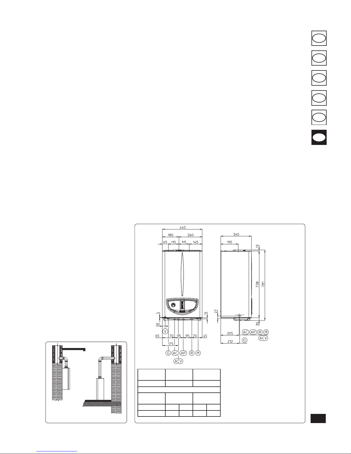
1.2 MAIN DIMENSIONS.
e plugs (standard supply) are to be used only in
conjunction with the mounting brackets or xing
template to x the appliance to the wall; they only
ensure adequate support if inserted correctly
(according to technical standards) in walls made
of solid or semi-hollow brick or block. In the
case of walls made from hollow brick or block,
partitions with limited static properties, or in any
case walls other than those indicated, a static test
must be carried out to ensure adequate support.
N.B.: the hex head screws supplied in the blister
pack are to be used exclusively to x the relative
mounting bracket to the wall.
ese boilers are used to heat water to below
boiling temperature in atmospheric pressure.
ey must be attached to a heating system suitable for their capacity and voltage.
Height
(mm)
Width
(mm)
Depth
(mm)
781 440 340
CONNECTIONS
GAS
DOMESTIC
HOT WATER
SYSTEM
G AC AF R M
3/4” 1/2” 1/2” 3/4” 3/4”
Fig. 1-2
Key:
G - Gas supply
AC - Domestic hot water outlet
ACV - Solar valve kit DHW inlet (Optional)
AF - Domestic cold water inlet
R - System return
M - System ow
V - Electrical connection
N.B.: connection group (optional)
YES
NO
144
GR
CZ
HU
ES
IE
PT
1.3 ANTIFREEZE PROTECTION.
Minimum temperature -5°C. e boiler is sup-
plied with an antifreeze function as standard that
activates the pump and burner when the system
water temperature in the boiler falls below 4°C.
e anti-freeze function is only guaranteed if:
- the boiler is correctly connected to gas and
electricity power supply circuits;
- the boiler is powered constantly;
- the boiler is not in “O” mode;
- the boiler is not in no ignition block (Par.2.5);
- the boiler essential components are not faulty.
In these conditions the boiler is protected against
freezing to an environmental temperature of -5°C.
Minimum temperature -15°C. If the boiler is
installed in a place where the temperature falls
below -5°C and in the event there is no gas or
the boiler goes into ignition block, the appliance
can freeze.
To prevent the risk of freezing follow the instructions below:
- protect the central heating circuit from freezing by introducing a good quality anti-freeze
liquid (specically for central heating systems),
carefully following the manufacturer’s instructions regarding the percentage necessary with
respect to the minimum temperature required
for preserving the system.
The materials the boilers are made from are
resistant to ethylene and propylene glycol-based
anti-freeze liquids.
For life and possible disposal, follow the supplier’s
instructions.
- Protect the domestic hot water circuit against
freezing by using an accessory that is supplied
on request (anti-freeze kit) comprising two
electric heating elements, the relevant cables
and a control thermostat (carefully read the
installation instructions contained in the accessory kit pack).
Boiler anti-freeze protection is thus ensured only if:
- the boiler is correctly connected to electricity
power supply circuits;
- main switch is inserted;
- the anti-freeze kit components are ecient.
In these conditions the boiler is protected against
freezing to temperature of -15°C.
e warranty does not cover damage due to interruption of the electrical power supply and failure
to comply with that stated on the previous page.
N.B.: if the boiler is installed in places where
the temperature falls below 0°C, the heating
attachment pipes must be insulated.
1.4 CONNECTIONS.
Gas connection (Appliance category II
2H3+
).
Our boilers are designed to operate with methane
gas (G20) and LPG. Supply pipes must be the
same as or larger than the 3/4”G boiler tting.
Before connecting the gas line, carefully clean
inside all the fuel feed system pipes to remove any
residue that could impair boiler eciency. Also
make sure the gas corresponds to that for which
the boiler is prepared (see boiler data-plate). If
dierent, the appliance must be converted for
operation with the other type of gas (see converting appliance for other gas types). e dynamic
gas supply (methane or LPG) pressure must also
be checked according to the type used in the
boiler, as insucient levels can reduce generator
output and cause malfunctions.
Ensure correct gas cock connection. e gas
supply pipe must be suitably dimensioned according to current regulations in order to guarantee
correct gas ow to the burner even in conditions
of maximum generator output and to guarantee
appliance eciency (technical specications).
e coupling system must conform to standards.
Fuel gas quality. e appliance has been designed to operate with gas free of impurities; otherwise it is advisable to t special lters upstream
from the appliance to restore the purity of the gas.
Storage tanks (in case of supply from LPG
depot).
- New LPG storage tanks may contain residual
inert gases (nitrogen) that degrade the mixture
delivered to the appliance casing functioning
anomalies.
- Due to the composition of the LPG mixture,
layering of the mixture components may occur
during the period of storage in the tanks. is
can cause a variation in the heating power of
the mixture delivered to the appliance, with
subsequent change in its performance.
Hydraulic connection.
Important: In order not to void the warranty
before making the boiler connections, carefully
clean the heating system (pipes, radiators, etc.)
with special pickling or de-scaling products to
remove any deposits that could compromise
correct boiler operation.
In compliance with Standards in force it is mandatory to treat the water in the heating system
chemically in order to protect the system and
appliance from deposits of lime scale.
Hydraulic connections must be made in a
rational way using the couplings on the boiler
template. e boiler safety valves outlet must be
connected to a draining funnel. Otherwise, the
manufacturer declines any responsibility in case
of ooding if the drain valve cuts in.
Important: to preserve the duration of appliance
eciency features, in the presence of water whose
features can lead to the deposit of lime scale,
installation of the “polyphosphate dispenser” kit
is recommended. On the basis of the Standards in
force, it is mandatory to treat the water with over
25 French degrees in the heating circuit and over
15 French degrees for DHW using conditioning
chemicals for powers < 100 kW or with soeners
for powers > 100 kW.
Electrical connection: e “Maior Eolo” boiler
has an IPX5D protection rating for the entire
appliance. Electrical safety of the unit is reached
when it is correctly connected to an ecient
earthing system as specied by current safety
standards.
Imp ortant: Immergas S.p.A. declines any
responsibility for damage or physical injur y
caused by failure to connect the boiler to an
ecient earth system or failure to comply with
the reference standards.
Also ensure that the electrical installation corresponds to maximum absorbed power specications
as shown on the boiler data-plate. Boilers are supplied complete with an “X” type power cable without
plug. e power supply cable must be connected to
a 230V ±10% / 50Hz mains supply respecting L-N
polarity and earth connection .
is network
must also have a multi-pole circuit breaker with
class III over-voltage category. When replacing the
power supply cable, contact a qualied technician
(e.g. the Immergas Aer-Sales Technical Assistance
Service). e power cable must be laid as shown.
In the event of mains fuses replacement on the
connection board, use a 3.15A quick-blow fuses.
For the main power supply to the appliance,
never use adapters, multiple sockets or extension leads.
145
GR
CZ
HU
ES
IE
PT
Important: if the system is subdivided into zones
using the relevant kit. the CARV2 must be used
with its climate thermostat function disabled, i.e.
it must be set to On/O mode.
Comando Amico Remoto remote controlV2or
On/Off chrono-thermostat electrical connections (Optional). e operations described
below must be performed aer having removed
the voltage from the appliance. Any thermostat
or On/O environment chrono-thermostat must
be connected to clamps 40 and 41 eliminating
jumper X40 (Fig. 3-2). Make sure that the On/
O thermostat contact is of the “clean” type, i.e.
independent of the mains supply, otherwise the
electronic adjustment card would be damaged.
Any Comando Amico Remoto remote controlV2
must be connected to clamps 40 and 41 eliminating jumper X40 on the circuit board, paying
attention not to invert the connections (Fig. 3-2).
Important: if the Comando Amico Remoto
remote controlV2 or any other On/O chronothermostat is used arrange two separate lines in
compliance with current regulations regarding
electrical systems. No boiler pipes must ever be
used to earth the electric system or telephone lines. Ensure elimination of this risk before making
the boiler electrical connections.
1.6 EXTERNAL PROBE OPTIONAL.
e boiler is prepared for the application of the
external probe (Fig. 1-7), which is available as
an optional kit.
e probe can be connected directly to the boiler
electrical system and allows the max. system
ow temperature to be automatically decreased
when the external temperature increases, in
order to adjust the heat supplied to the system
according to the change in external temperature.
e external probe always acts when connected
independently from the presence or type of room
thermostat used. e correlation between system
ow temperature and external temperature is determined by the position of the selector switch on
the boiler control panel according to the curves
shown in the diagram (Fig. 1-8). e electric connection of the external probe must be made on
clamps 38 and 39 on the boiler P.C.B. (Fig. 3-2).
1.5 REMOTE CONTROLS AND
ROOM CHRONOTHERMOSTATS
OPTIONAL.
e boiler is prepared for the application of room
chrono-thermostats or remote controls, which
are available as optional kits.
All Immergas chrono-thermostats are connected with 2 wires only. Carefully read the user
and assembly instructions contained in the
accessory kit.
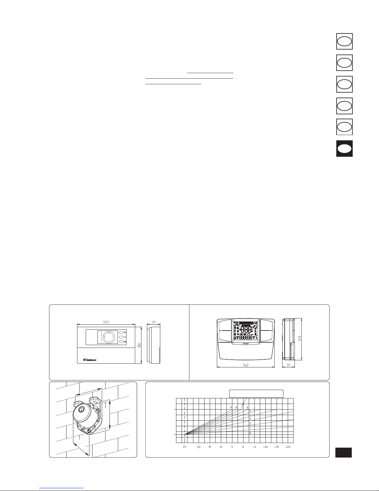
• On/O digital chrono-thermostat (Fig. 1-5).
e chrono-thermostat allows:
- to set two room temperature values: one for
day (comfort temperature) and one for night
(lower temperature);
- to set up to four on/o dierential weekly
programs;
- to select the required operating mode from
the various possible alternatives:
• permanent functioning in comfort temp;
• permanent functioning in reduced temp;
• permanent functioning in adjustable anti-
freeze temp.
e chrono-thermostat is powered by two 1.5V
LR 6 type alkaline batteries.
• Comando Amico Remoto Remote Control De-
viceV2 (CARV2) with climate chrono-thermostat
function. In addition to the functions described
in the previous point, the CAR panelV2 enables
the user to control all the important information regarding operation of the appliance
and the heating system with the opportunity
of easily intervening on the previously set
parameters without having to go to the place
where the appliance is installed. e panel is
provided with self-diagnosis to display any
boiler functioning anomalies. e climate chrono-thermostat incorporated into the remote
panel enables the system ow temperature to
be adjusted to the actual needs of the room
being heated, in order to obtain the desired
room temperature with extreme precision and
therefore with evident saving in running costs.
e chrono-thermostat is fed directly by the
boiler by means of the same 2wires used for
the transmission of data between boiler and
chrono-thermostat.
45
31
58
Fig. 1-8
Fig. 1-7
On/O digital chrono-thermostat.
Comando Amico Remoto remote controlV2 (CARV2)
Fig. 1-6
Fig. 1-5
POSITION OF THE CENTRAL HEATING
TEMPERATURE USER ADJUSTMENT
TM (°C)
TE (°C)
FLOW T.
TE (°C)
146
GR
CZ
HU
ES
IE
PT
1.7 IMMERGAS FLUE SYSTEMS.
Immergas supplies various solutions separately
from the boiler regarding the installation of air
intake terminals and ue extraction, which are
fundamental for boiler operation.
Important: e boiler must only be installed
together with an original Immergas air intake
and ue gas exhaust system. is system can be
identied by an identication mark and special
distinctive marking bearing the note: “not for
condensing boilers”.
e ue exhaust pipes must not be in contact with
or be near to ammable materials. Moreover,
they must not pass through buildings or walls
made of ammable material.
See following paragraphs for the detailed description of the kits available.
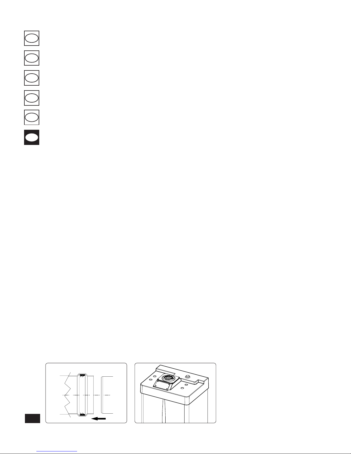
Positioning of double lip seals. For correct
positioning of lip seals on elbows and extensions,
follow the direction of assembly given in gure
(Fig. 1-9).
• Resistance factors and equivalent lengths. Each
ue extraction system component has a Resi-
stance Factor based on experimental tests and
specied in the table below. e resistance factor
for individual components is independent from
the type of boiler on which it is installed or the
actual dimensions. It is, however, conditioned
by the temperature of the uids that pass through the pipe and therefore varies according to
applications for air intake or ue exhaust. Each
single component has a resistance corresponding
to a certain length in metres of pipe of the same
diameter; the so-called equivalent length, obtained
from the ration between the relative Resistance
Factors. All boilers have an experimentally obtaina-
ble maximum Resistance Factor equal to 100. e
maximum Resistance Factor allowed corresponds
to the resistance encountered with the maximum
allowed pipe length for each type of Terminal
Kit. is information enables calculations to be
made in order to verify the possibility of various
congurations of ue extraction systems.
1.8 INSTALLAZIONE ALL’ESTERNO
IN LUOGO PARZIALMENTE
PROTETTO.
N.B.: a partially protected area is one in which the
appliance is not exposed to the direct action of the
weather (rain, snow, hail, etc..).
• Conguration type B, open chamber and fan
assisted.
The relevant terminal must be used for this
conguration (present in the intake kit for the
installation in question), which must be placed
on the central hole of the boiler (Fig. 1-12). Air
intake takes place directly from the environment
in which the boiler is installed and ue exhaust
in individual ue or to the outside.
In this conguration the boiler is classied as
type B22.
With this conguration:
- air intake takes place directly from the environ-
ment in which the boiler is installed and only
functions in permanently ventilated rooms;
- the ue exhaust must be connected to its own
individual ue or channelled directly into the
external atmosphere.
The technical regulations in force must be
respected.
Flue gas separator adjustment. For correct
functioning of the boiler in conguration with
direct intake it is necessary to regulate the ue
gas shutter according to that stated in the relative
tables (Fig. 1-14).
• Cover kit assembly (Fig. 1-11). Remove the
two plugs and the gaskets present from the two
lateral holes with respect to the central one. Now
cover the right intake hole using the relevant
plate, xing it onto the le side using the two
supplied screws. Install the Ø80 outlet ange on
the central hole of the boiler, taking care to insert
the gasket supplied with the kit and tighten by
means of the screws provided. Install the upper
cover, xing it using the 4 screws present in the
kit, positioning the relevant gaskets. Engage the
90° Ø80 bend with the male end (smooth) in
the female end (with lip seal) of the Ø80 ange
unit until it stops. Introduce the gasket, making
it run along the bend. Fix it using the sheet steel
plate and tighten by means of the straps present
in the kit, making sure to block the 4 gasket
aps. Fit the male end (smooth) of the exhaust
terminal into the female end of the bend 90°
Ø80, making sure that the relevant wall sealing
plate is already tted; this will ensure hold and
joining of the elements making up the kit.
• Coupling of extension pipes. To install pushtting extensions with other elements of the
ue extraction elements assembly, proceed as
follows: Install the pipe or elbow with the male
side (smooth) in the female section (with lip
seal) to the stop on the previously installed
element. is will ensure sealing eciency of
the coupling.
Max. length of exhaust duct. The flue pipe
(vertical or horizontal) can be extended to a
max. length of 12 m straight route, using insulated
pipes (Fig. 1-31). To prevent problems of ue gas
condensate in the exhaust pipe Ø 80, due to ue
gas cooling through the wall, the length of the
pipe (not insulated) must be limited to just 5 m.
Example of installation with direct vertical
terminal in partially protected location. When
the vertical terminal for direct discharge of combustion products is used, a minimum gap of 300
mm must be le between the terminal and the
balcony above. e height A + B (always with
respect to the balcony above), must be equal to
or greater than 2000 mm. (Fig. 1-13).
• Configuration without cover kit (boiler
typeC).
By leaving the side plugs tted, it is possible to
install the appliance externally, in partially covered places, without the cover kit. Installation
takes place using the Ø60/100 and Ø 80/125
concentric horizontal intake/ exhaust kits. Refer
to the paragraph relative to indoor installation.
In this conguration the top cover kit guarantees
additional protection for the boiler. It is recommended but not compulsory.
Fig. 1-9
Fig. 1-10

147
GR
CZ
HU
ES
IE
PT
Fig. 1-12
Fig. 1-13
Fig. 1-11
Fig. 1-14
Fig. 1-15
Flue gas separator adjustment. For correct functioning of the boiler it is necessary to regulate
the ue gas shutter positioned on the air/ue gas
sample points (Fig. 1-14).
Adjustment is carried out by loosening the
front retainer screw and moving the indicator
to the correct position, aligning its value to the
horizontal reference. Once adjustment has been
performed, tighten the screw to x the separator.
Appropriate adjustment takes place on the basis
of the type of pipe and its extension: this calculation can be carried out using the relevant tables.
Intake diaphragm installation. For correct boiler functioning with Ø80 separator kits and drain
measuring > 1 m a diaphragm must be installed
on the sealed chamber intake hole and before
the intake pipe (Fig. 1-15). e choice of suitable
diaphragm takes place on the basis of the type of
pipe and its maximum extension: this calculation
can be carried out using the following tables:
N.B.: the diaphragms are supplied together with
the boiler.
DIAPHRAGM
e cover kit includes:
N° 1 Heat moulded cover
N° 1 Gasket clamping plate
N° 1 Gasket
N° 1 Gasket clamp
N° 1 N°1 Intake hole covering
plate
e terminal kit includes:
N° 1 Gasket
N° 1 Exhaust ange Ø80
N° 1 Bend 90° Ø80
N° 1 Exhaust pipe Ø80
N° 1 Wall sealing plate
VERTICAL TERMINAL KIT FOR
DIRECT DRAINING
INTAKE COVER KIT
148
GR
CZ
HU
ES
IE
PT
Shutter regulation table
Maior Eolo 24 4E.
Shutter regulation table
Maior Eolo 28 4E.
Shutter regulation table
Maior Eolo 32 4E.
Flue gas shutter notch
Type of installation
(duct length in metres)
1 3 4 5 6 10
Ø60/100 horizontal concentric kit - - Da 0 a 0,5 Da 0,5 a 1,5 - Da 1,5 a 3,0
Ø60/100 vertical concentric kit - - Da 0 a 2,2 Da 2,2 a 3,7 - Da 3,7 a 4,7
Ø80/125 horizontal concentric kit - - Da 0 a 0,5 Da 0,5 a 4,6 - Da 4,6 a 7,4
Ø80/125 vertical concentric kit - - Da 0 a 5,4 Da 5,4 a 9,5 - Da 9,5 a 12,2
Ø80 vertical separator kit without bends *Da 0 a 20 *Da 20 a 40 **Da 0 a 22 - - **Da 22 a 32
Ø80 horizontal separator kit with two bend *Da 0 a 16 *Da 16 a 35 **Da 0 a 17 - - **Da 17 a 28
Direct intake kit and Ø80 drain in B22 conguration - - Da 0 a 1 - Da 1 a 12 -
* ese maximum extension values are considered intake with 1 metre drain pipe
** ese maximum extension values are considered in draining with 1 metre intake pipe and Ø44 diaphragm on the intake hole.
Type of installation
(duct length in metres)
2 4 7 10
Ø60/100 horizontal concentric kit - Da 0 a 0,5 Da 0,5 a 1,5 Da 1,5 a 3,0
Ø60/100 vertical concentric kit - Da 0 a 2,2 Da 2,2 a 3,7 Da 3,7 a 4,7
Ø80/125 horizontal concentric kit - Da 0 a 0,5 Da 0,5 a 4,6 Da 4,6 a 7,4
Ø80/125 vertical concentric kit - Da 0 a 5,4 Da 5,4 a 9,5 Da 9,5 a 12,2
Ø80 vertical separator kit without bends *Da 0 a 20 *Da 20 a 40 **Da 0 a 22 ** Da 22 a 32
Ø80 horizontal separator kit with two bend *Da 0 a 16 *Da 16 a 35 **Da 0 a 17 ** Da 17 a 28
Direct intake kit and Ø80 drain in B22 conguration Da 0 a 1 - Da 1 a 12 -
* ese maximum extension values are considered intake with 1 metre drain pipe
** ese maximum extension values are considered in draining with 1 metre intake pipe and Ø 50 diaphragm on the intake hole.
Type of installation
(duct length in metres)
3 4 5 6 10
Ø60/100 horizontal concentric kit - - Da 0 a 0,5 Da 0,5 a 1,5 Da 1,5 a 3,0
Ø60/100 vertical concentric kit - - Da 0 a 2,2 Da 2,2 a 3,7 Da 3,7 a 4,7
Ø80/125 horizontal concentric kit - - Da 0 a 0,5 Da 0,5 a 4,6 Da 4,6 a 7,4
Ø80/125 vertical concentric kit - - Da 0 a 5,4 Da 5,4 a 9,5 Da 9,5 a 12,2
Ø80 vertical separator kit without bends *Da 0 a 20 *Da 20 a 40 **Da 0 a 22 - **Da 22 a 32
Ø80 horizontal separator kit with two bend *Da 0 a 16 *Da 16 a 35 **Da 0 a 17 - **Da 17 a 28
Direct intake kit and Ø80 drain in B22 conguration - Da 0 a 1 - Da 1 a 12 -
* ese maximum extension values are considered intake with 1 metre drain pipe
** ese maximum extension values are considered in draining with 1 metre intake pipe and Ø 50 diaphragm on the intake hole.
149
GR
CZ
HU
ES
IE
PT
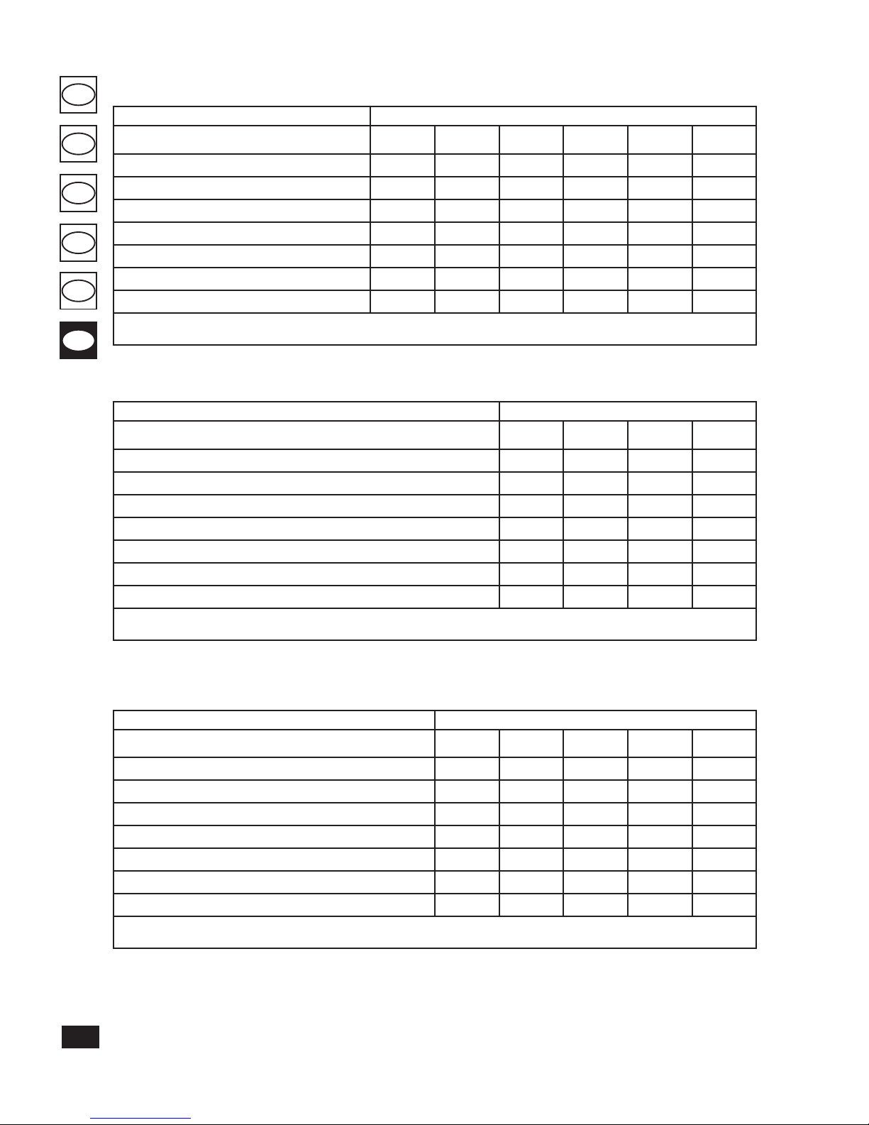
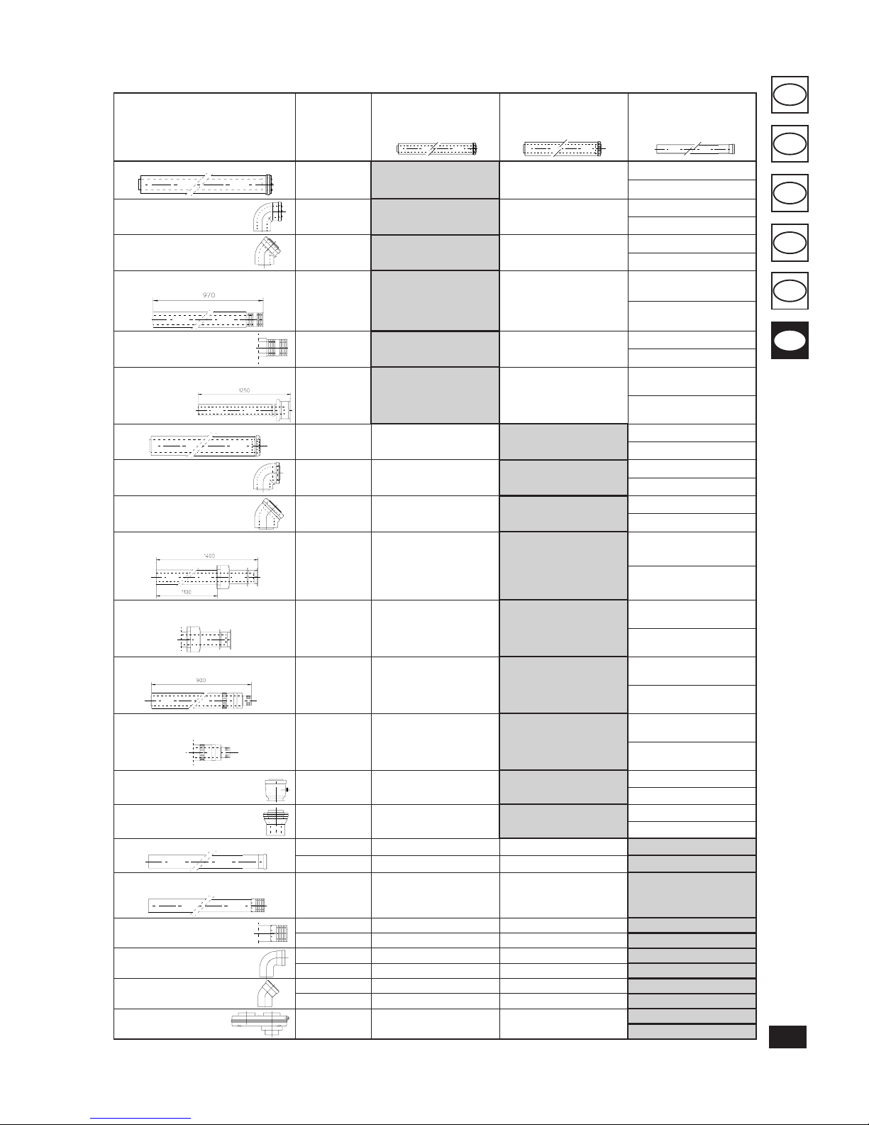
Tables of Resistance Factors and Equivalent Lengths.
DUCT TYPE
Resistance
Factor
(R)
Equivalent
length in m of
concentric pipe
Ø60/100
Equivalent
length in m of concentric
pipe
Ø80/125
Equivalent
length
in m of pipe
Ø80
Concentric pipe Ø60/100 m 1
Intake and
Exhaust 16,5
m 1 m 2,8
Intake m 7,1
Exhaust m 5,5
Concentric bend 90° Ø60/100
Intake and
Exhaust 21
m 1,3 m 3,5
Intake m 9,1
Exhaust m 7,0
Concentric bend 45° Ø60/100
Intake and
Exhaust 16,5
m 1 m 2,8
Intake m 7,1
Exhaust m 5,5
Terminal complete with concentric
horizontal intake-exhaust Ø60/100
Intake and
Exhaust 46
m 2,8 m 7,6
Intake m 20
Exhaust m 15
Terminal complete with horizontal
intake-exhaust Ø60/100
Intake and
Exhaust 32
m 1,9 m 5,3
Intake m 14
Exhaust m 10,6
Terminal complete with concentric vertical
intake-exhaust Ø60/100
Intake and
Exhaust 41,7
m 2,5 m 7
Intake m 18
Exhaust 14
Concentric pipe Ø80/125 m 1
Intake and
Exhaust 6
m 0,4 m 1,0
Intake m 2,6
Exhaust m 2,0
Concentric bend 90° Ø80/125
Intake and
Exhaust 7,5
m 0,5 m 1,3
Intake m 3,3
Exhaust m 2,5
Concentric bend 45° Ø80/125
Intake and
Exhaust 6
m 0,4 m 1,0
Intake m 2,6
Exhaust m 2,0
Terminal complete with intake-exhaust
vertical concentric Ø80/125
Intake and
Exhaust 33
m 2,0 m 5,5
Intake m 14,3
Exhaust m 11,0
Terminal complete with concentric vertical
intake-exhaust Ø80/125
Intake and
Exhaust 26,5
m 1,6 m 4,4
Intake m 11,5
Exhaust m 8,8
Terminal complete with concentric
horizontal intake-exhaust Ø80/125
Intake and
Exhaust 39
m 2,3 m 6,5
Intake m 16,9
Exhaust m 13
Terminal complete with horizontal
intake-exhaust Ø80/125
Intake and
Exhaust 34
m 2,0 m 5,6
Intake m 14,8
Exhaust m 11,3
Concentric adapter from Ø60/100
to Ø80/125 with condensate trap
Intake and
Exhaust 13
m 0,8 m 2,2
Intake m 5,6
Exhaust m 4,3
Concentric adapter from Ø60/100
to Ø80/125
Intake and
Exhaust 2
m 0,1 m 0,3
Intake m 0,8
Exhaust m 0,6
Pipe Ø80 m 1 (with and without insulation)
Intake 2,3 m 0,1 m 0,4 Intake m 1,0
Exhaust 3 m 0,2 m 0,5 Exhaust m 1,0
Complete air intake terminal Ø80
m 1
(with or without insulation)
Intake 5 m 0,3 m 0,8 Intake m 2,2
Intake terminal Ø80
Exhaust terminal Ø80
Intake 3 m 0,2 m 0,5 Intake m 1,3
Exhaust 2,5 m 0,1 m 0,4 Exhaust m 0,8
Bend 90° Ø80
Intake 5 m 0,3 m 0,8 Intake m 2,2
Exhaust 6,5 m 0,4 m 1,1 Exhaust m 2,1
Bend 45° Ø80
Intake 3 m 0,2 m 0,5 Intake m 1,3
Exhaust 4 m 0,2 m 0,6 Exhaust m 1,3
Parallel split Ø80 from
Ø60/100 to Ø80/80
Intake and
Exhaust 8,8
m 0,5 m 1,5
Intake m 3,8
Exhaust m 2,9
150
GR
CZ
HU
ES
IE
PT
C12
1.9 INDOOR INSTALLATION.
• Type C conguration, sealed chamber and
fan assisted.
Horizontal intake - exhaust kit Ø60/100. Kit
assembly (Fig. 1-16): install the bend with ange
(2) onto the central hole of the boiler inserting
the gasket (1) and tighten using the screws in the
kit. Couple the terminal pipe (3) with the male
end (smooth) into the female end of the bend
(with lip seals) up to the stop; making sure that
the internal wall sealing plate and external wall
sealing plate have been tted, this will ensure
sealing and joining of the elements making up
the kit.
Note: when the boiler is installed in areas where
very rigid temperatures can be reached, a special
anti-freeze kit is available that can be installed as
an alternative to the standard kit.
• Coupling extension pipes and concentric
elbows Ø60/100. To snap-t extensions with
other elements of the ue extraction elements,
operate as follows engage the concentric pipe
or elbow with the male side (smooth) on the
female section (with lip seal) up to the stop
on the previously installed element. is will
ensure sealing and joining of the elements
correctly.
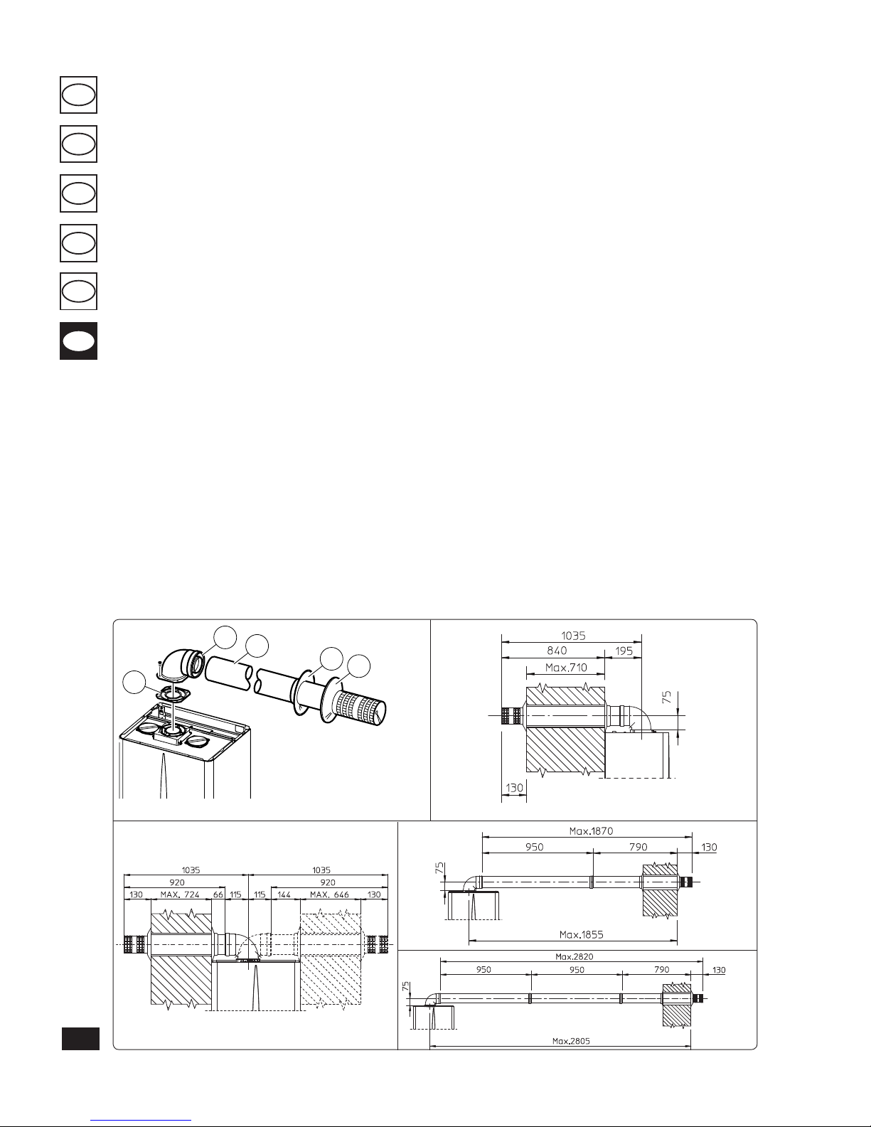
e Ø60/100 horizontal intake/exhaust kit can
be installed with the rear, right side, le side and
front outlet.
• Application with rear outlet (Fig. 1-17). e
970 mm pipe length enables routing through
a maximum thickness of 710 mm. Normally
the terminal must be shortened. Calculate
the distance by adding the following values:
Part thickness + internal projection + external projection. e minimum indispensable
projection values are given in the gure.
• Application with side outlet (Fig. 1-18); Using
the horizontal intake-exhaust kit, without the
special extensions, enables routing through
a wall thickness of 724 mm with the le side
outlet and 646 with the right side outlet.
• Extensions for horizontal kit. e horizontal
intake-exhaust kit Ø 60/100 can be extended
up to a max. horizontal distance of 3,000 mm
including the terminal with grid and excluding
the concentric bend leaving the boiler. is
conguration corresponds to a resistance factor
of 100. In these cases the special extensions
must be requested.
Connection with N°1 extension (Fig. 1-19).
Max. distance between vertical boiler axis and
external wall is 1855mm.
Connection with N°2 extensions (Fig. 1-20).
Max. distance between vertical boiler axis and
external wall is 2805mm.
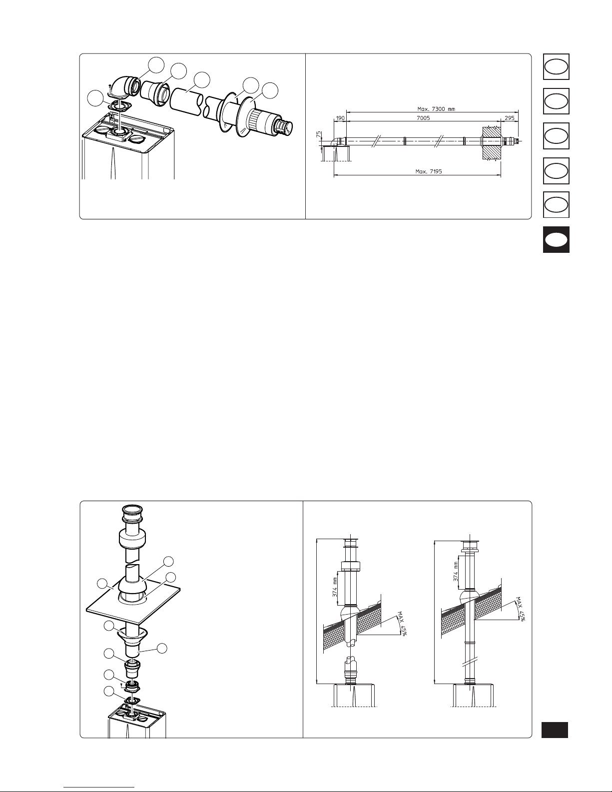
Horizontal intake-exhaust kit Ø80/125. Kit
assembly (Fig. 1-21): install the bend with ange
(2) onto the central hole of the boiler inserting
the gasket (1) and tighten using the screws in the
kit. Fit the male end (smooth) of the adapter (3)
up to the stop on the female end of the bend (2)
(with lip seal). Fit the Ø 80/125 (4) concentric
terminal pipe with the male end (smooth) to the
female end of the adapter (3) (with lip gasket) up
to the stop; making sure that the internal wall
sealing plate and external wall sealing plate have
been tted, this will ensure sealing and joining
of the elements making up the kit.
• Coupling extension pipes and concentric elbows
Ø80/125. To snap-t extensions with other elements of the ue extraction elements, operate as
follows engage the concentric pipe or elbow with
the male side (smooth) on the female section
(with lip seal) up to the stop on the previously
installed element. is will ensure sealing and
joining of the elements correctly.
Important: if the exhaust terminal and/or extension concentric pipe needs shortening, consider
that the internal pipe must always protrude by
5mm with respect to the external pipe.
Normally the Ø80/125 horizontal intake-exhaust
kit is used if particularly long extensions are required; the Ø80/125 kit can be installed with the
rear, right side, le side or front outlet.
• Extensions for horizontal kit. e Ø80/125
horizontal intake-exhaust kit can be extended
up to a max. horizontal distance of 7,300 mm
including the terminal with grid and excluding
the concentric bend leaving the boiler and the
adapter Ø60/100 in Ø80/125 (Fig. 1-22). is
conguration corresponds to a resistance factor
of 100. In these cases the special extensions
must be requested.
N.B.: when installing the ducts, a section clamp
with pin must be installed every 3 metres.
• External grill. N.B.: for safety purposes, do not
even temporarily obstruct the boiler intake/
exhaust terminal.
Fig. 1-16
C12
C12 C12
C12
Fig. 1-17
Fig. 1-19
Fig. 1-20
Fig. 1-18
1
3
2
4
5
e kit includes:
N°1 - Gasket (1)
N°1 - Concentric bend 90° (2)
N°1 - Intake-exhaust concentric pipe
Ø60/100 (3)
N°1 - Internal white wall sealing plate (4)
N°1 - External grey wall sealing plate (5)
151
GR
CZ
HU
ES
IE
PT
C32
Fig. 1-25Fig. 1-24
C32
Fig. 1-21
C12
Fig. 1-22
Vertical kit with aluminium tile Ø80/125. Kit
assembly (Fig. 1-24): install the concentric ange
(2) on the central hole of the boiler inserting the
gasket (1) and tighten using the screws in the
kit. Fit the male end (smooth) of the adapter (3)
into the female end of the concentric ange (2).
Imitation aluminium tile installation. Replace the
tile with the aluminium sheet (5), shaping it to
ensure that rainwater runs o. Position the xed
half-shell (7) and insert the intake-exhaust pipe
(6). Fit the Ø 80/125 concentric terminal pipe
with the male end (6) (smooth) to the female
end of the adapter (3) (with lip gasket) up to the
stop; making sure that the wall sealing plate has
been tted, this will ensure sealing and joining
of the elements making up the kit.
• Coupling extension pipes and concentric
elbows. To install push-fitting extensions
with other elements of the flue extraction
elements assembly, proceed as follows: engage
the concentric pipe or elbow with the male
side (smooth) on the female section (with lip
seal) up to the stop on the previously installed
element. is will ensure sealing and joining
of the elements correctly.
Important: if the exhaust terminal and/or extension concentric pipe needs shortening, consider
that the internal pipe must always protrude by
5mm with respect to the external pipe.
is specic terminal enables ue exhaust and
air intake, necessary for combustion, in a vertical
direction.
N.B.: e Ø80/125 vertical kit with aluminium
tile enables installation on terraces and roofs
with a maximum slope of 45% (25°) and the
height between the terminal cap and half-shell
(374mm) must always be respected.
e vertical kit with this conguration can be
extended up to a maximum of 12,200 mm vertical
rectilinear, with the terminal included (Fig. 1-25).
is conguration corresponds to a resistance
factor of 100. In this case the special extensions
must be requested.
The terminal Ø 60/100 can also be used for
vertical exhaust, in conjunction with concentric
flange code 3.011141 (sold separately). The
height between the terminal cap and half-shell
(374mm) must always be respected.
e vertical kit with this conguration can be
extended up to a maximum of 4,700 mm vertical
rectilinear, with the terminal included (Fig. 1-25).
Separator kit Ø80/80. e Ø80/80 separator kit,
allows separation of the exhaust ues and air intake
pipes according to the diagram shown in the gure .
Combustion products are expelled from pipe (S).
Air is taken in through pipe (A) for combustion.
e intake pipe (A) can be installed either on the
right or le hand side of the central exhaust pipe
(S). Both ducts can be routed in any direction.
• Kit assembly (Fig. 1-26): install ange (4) on the
central hole of the boiler, tting gasket (1) and
tighten with the at-tipped hex screws included
in the kit. Remove the at ange present in the
lateral hole with respect to the central one (according to needs) and replace it with the ange
(3), positioning the gasket (2) already present in
the boiler and tighten using the supplied selfthreading screws. Fit the male end (smooth) to
the bends (5) in the female end of the anges
(3 and 4). Fit the intake terminal (6) with the
male section (smooth) in the female section of
the bend (5) up to the stop, ensuring that the
internal and external wall sealing plates are
tted. Fit the exhaust pipe (9) with the male end
(smooth) to the female end of the bend (5) up
to the stop; making sure that the internal wall
sealing plate has been tted, this will ensure
sealing and joining of the elements making up
the kit.
e kit includes:
N°1 - Gasket (1)
N°1 - Female concentric ange
(2)
N°1 - Adapter Ø60/100
for Ø80/125 (3)
N°1 - Wall sealing plate (4)
N°1 - Aluminium tile (5)
N°1 - Concentric intake-
exhaust terminal
Ø80/125 (6)
N°1 - Fixed half-shell (7)
N°1 - Mobile half-shell (8)
1
3
2
5
6
4
1
2
3
4
6
5
7
8
e kit includes:
N°1 - Gasket (1)
N°1 - Concentric bend Ø60/100 (2)
N°1 - Adapter Ø60/100 for Ø80/125 (3)
N°1 - Int./exhaust concentric terminal
Ø80/125 (4)
N°1 - Internal white wall sealing plate (5)
N°1 - External grey wall sealing plate (6)
C12
MAXIMUM LENGTH 12200 mm
MAXIMUM LENGTH 4,700 mm
 Loading...