

Page 1
Instruction and
*1.038946ENG*
recommendation booklet
IE
MAGIS VICTRIX
ERP
Page 2

Page 3

Dear Customer,
Our compliments for having chosen a top-quality Immergas product, able to assure well-being and safety for a long period of time. As an Immergas customer
you can also count on a qualied aer-sales service, prepared and updated to guarantee constant eciency of your boiler. Read the following pages carefully: you
will be able to draw useful suggestions regarding the correct use of the appliance, the respect of which, will conrm your satisfaction for the Immergas product.
For assistance and scheduled maintenance contact Authorised Aer-Sales centres: they have original spare parts and are specically trained directly by the
manufacturer.
General recommendations
All Immergas products are protected with suitable transport packaging.
e material must be stored in dry environments protected against bad weather.
e instruction book is an integral and essential part of the product and must be consigned to the new user also in the case of transfer or succession of ownership.
It must be stored with care and consulted carefully, as all of the warnings provide important safety indications for installation, use and maintenance stages.
is instructions manual provides technical information for installing Immergas boilers. As for the other issues related to boiler installation (e.g. safety in the work
site, environment protection, injury prevention), it is necessary to comply with the provisions specied in the regulations in force and principles of good practice.
In compliance with legislation in force, the systems must be designed by qualied professionals, within the dimensional limits established by the Law. Installation
and maintenance must be performed in compliance with the regulations in force, according to the manufacturer's instructions and by an authorised company,
which has specic technical expertise in the system sector, as required by Law.
Improper installation or assembly of the Immergas appliance and/or components, accessories, kit and devices can cause unexpected problems to people, animals
and objects. Read the instructions provided with the product carefully to ensure a proper installation.
Maintenance must be carried out by an authorised company. e Authorised Aer-sales Service represents a guarantee of qualication and professionalism.
e appliance must only be destined for the use for which it has been expressly declared. Any other use will be considered improper and therefore potentially
dangerous.
If errors occur during installation, operation and maintenance, due to non compliance with technical laws in force, standards or instructions contained in this
book (or however supplied by the manufacturer), the manufacturer is excluded from any contractual and extra-contractual liability for any damages and the
appliance warranty is invalidated.
CE DECLARATION OF CONFORMITY
(according to ISO/IEC 17050-1)
e company IMMERGAS S.p.A., with registered oce in via Cisa Ligure 95 42041 Brescello (RE) whose design, manufacturing, and aer sale assistance
processes comply with the requirements of standard UNI EN ISO 9001:2008,
MAGIS VICTRIX ERP boilers comply with the following European Directives and Delegated European Regulations:
“Eco-design” Directive 2009/125/EC, “Energy labelling” Directive 2010/30/EC, EU Regulation 811/2013, EU Regulation 813/2013, “Gas Appliance” Directive 2009/142/EC, “Electromagnetic Compatibility” Directive 2004/108/EC, “Performance” Directive 92/42/EC and “Low Voltage” Directive 2006/95/EC.
Immergas S.p.A. declines all liability due to printing or transcription errors, reserving the right to make any modications to its technical and commercial
documents without prior notice.
DECLARES that:
Mauro Guareschi
Research & Development Director
Signature:
Page 4

INDEX
USER page INSTALLER page MAINTENANCE TECHNICIAN page
1 Boiler installation .......................................5
1.1 Installation recommendations. ................. 5
1.2 Main dimensions. .......................................6
1.3 Anti-freeze protection. ...............................6
1.4 Boiler connection unit. .............................. 7
1.5 Gas connection. ..........................................8
1.6 Hydraulic connection. ................................8
1.7 Electric connection. ...................................9
1.8 Immergas ue systems. ............................10
1.9 Tables of resistance factors and
equivalent lengths. ....................................10
1.10 Outdoor installation in partially
protected area.
1.11 Concentric horizontal kit installation. ... 13
1.12 Concentric vertical kit installation. ........14
1.13 Separator kit installation. .........................15
1.14 Adaptor C9 kit installation. ....................16
1.15 Ducting of ues or technical slots. .........17
1.16 Conguration type B, open chamber
and fan assisted for indoors. ....................17
1.17 Flue exhaust to ue/chimney. .................17
1.18 Flues, chimneys, chimney pots and
terminals. ................................................... 18
1.19 System lling. ............................................ 18
1.20 Condensate trap lling. ............................18
1.21 Gas system start-up. .................................18
1.22 Boiler start up (ignition). .........................18
1.23 Circulation pump......................................19
1.24 Kits available on request. .........................20
1.25 Boiler components. ...................................21
........................................... 12
2 Use and maintenance instructions .........22
2.1 Cleaning and maintenance. .....................22
2.2 General warnings. ..................................... 22
2.3 Control panel.............................................22
2.4 Description of functioning states ...........23
2.5 Using the boiler. ........................................24
2.6 Troubleshooting. .......................................25
2.7 Parameters and information menu. .......27
2.8 Boiler shutdown ........................................28
2.9 Restore central heating system pressure. 28
2.10 System drainage. .......................................28
2.11 Anti-freeze protection. ............................28
2.12 Case cleaning. ............................................ 28
2.13 Decommissioning. ....................................28
3 Boiler commissioning (initial check) .....29
3.1 Wiring diagram. ........................................29
3.2 Boiler Hydraulic diagram. .......................30
3.3 Installation example Hydraulic
Diagram . ...................................................31
3.4 Troubleshooting. .......................................31
3.5 Converting the boiler to other types
of gas.
3.6 Calibration of number of fan revs. ......... 32
3.7 Adjustment of the air-gas ratio. ..............33
3.8 Checks following conversion to
3.9 Programming the P.C.B. .......................... 34
3.10 central heating operation in
3.11 “Chimney Sweep” function. ....................38
3.12 Pump anti-block function. ......................38
3.13 three-way anti-block function. ...............38
3.14 Radiators anti-freeze function. ...............38
3.15 P.C.B. periodical self-check. ....................38
3.16 Automatic vent function. .........................38
3.17 Solar panels coupling function. ..............38
3.18 Yearly appliance check and
3.19 Casing removal. ........................................39
3.20 Variable heat output. ................................40
3.21 Combustion parameters. .........................40
3.22 Technical data. ..........................................41
3.23 Key for data nameplate. ...........................42
3.24 Technical parameters for combination
3.25 Product che (in compliance with
3.26 Parameters for lling in the package
.......................................................... 32
another type of gas....................................33
combination with the heat pump. ..........37
maintenance. .............................................38
boilers (in compliance with
Regulation 813/2013). ..............................43
Regulation 811/2013). ..............................43
che. ...........................................................44
Page 5
BOILER
1
INSTALLATION
1.1 INSTALLATION
RECOMMENDATIONS.
e Magis Victrix ErP boiler has been designed
uniquely for wall-installation, for the production of domestic hot water for household use
and the like; also, combined with the Immergas
heat pump, it heats and cools the rooms (cooling is performed by the heat pump only). e
heat pump is controlled directly by the boiler
circuit board.
e place of installation of the appliance and
relative Immergas accessories must have suitable
features (technical and structural) such to allow
(always in safety, efficiency and comfortable
conditions):
- installation (according to the provisions of the
technical legislation and technical regulations);
- maintenance operations (including scheduled,
periodic, routine and special maintenance);
- removal (to outdoors in the place for loading
and transporting the appliances and components) as well as their eventual replacement
with appliances and/or equivalent components.
e wall surface must be smooth, without any
protrusions or recesses enabling access to the
rear part. ey are not designed to be installed
on plinths or oors (Fig. 1-1).
By varying the type of installation the classication of the boiler also varies, precisely:
- Type B23 or B53 boiler if installed using the
relevant terminal for air intake directly from
the room in which the boiler has been installed.
- Type C boiler if installed using concentric
pipes or other types of pipes envisioned for
sealed chamber boilers for air intake and expulsion of ue gas.
Only professionally enabled companies are
authorised to install Immergas gas appliances.
Installation must be carried out according to
regulation standards, current legislation and in
compliance with local technical regulations and
the required technical procedures.
Before installing the appliance, ensure that it is
delivered in perfect condition; if in doubt, contact
the supplier immediately. Packing materials (staples, nails, plastic bags, polystyrene foam, etc.)
constitute a hazard and must be kept out of the
reach of children. If the appliance is installed inside or between cabinets, ensure sucient space
for normal servicing; therefore it is advisable to
leave clearance of at least 3 cm between the boiler
casing and the vertical sides of the cabinet. Leave
adequate space above the boiler for possible water
and ue removal connections. Keep all ammable objects away from the appliance (paper, rags,
plastic, polystyrene, etc.).
Do not place household appliances underneath
the boiler as they could be damaged if the safety
valve intervenes with an obstructed conveying
system (the safety valve must be conveyed away
by a draining funnel), or if there are leaks from
the hydraulic connections; on the contrary, the
manufacturer cannot be held responsible for
any damage caused to the household appliances.
For the aforementioned reasons, we recommend
not placing furnishings, furniture, etc. under
the boiler.
In the event of malfunctions, faults or incorrect
operation, turn the appliance o and contact an
authorised company (e.g. the Authorised Technical Assistance centre, which has specically
trained sta and original spare parts). Do not
attempt to modify or repair the appliance alone.
Failure to comply with the above implies personal
responsibility and invalidates the warranty.
• Installation regulations:
- this boiler can be installed outdoors in a
partially protected area. A partially protected
area is one in which the appliance is not
exposed to the direct action of the weather
(rain, snow, hail, etc..).
is type of installation is only possible when
permitted by the laws in force in the appliance's
country of destination.
- Installation in places with a re risk is prohibited (for example: garages, closed parking
stalls), gas appliances and relative ue ducts,
ue exhaust pipes and combustion air intake
pipes.
- Installation is prohibited on the vertical
projection of cooking hobs.
- Installation is also forbidden in places/rooms
that constitute common parts of apartment
buildings such as stairs, cellars, entrance
halls, attics, los, escape routes, etc. unless
otherwise provided by local regulations.
Attention: wall mounting of the boiler must
guarantee stable and ecient support for the
generator
e plugs (standard supply) are to be used only in
conjunction with the mounting brackets or xing
template to x the appliance to the wall; they only
ensure adequate support if inserted correctly (according to technical standards) in walls made of
solid or semi-hollow brick or block. In the case of
walls made from hollow brick or block, partitions
with limited static properties, or in any case walls
other than those indicated, a static test must be
carried out to ensure adequate support.
N.B.: the hex head screws supplied in the blister
pack are to be used exclusively to x the relative
mounting bracket to the wall.
ese boilers are used to heat water to below
boiling temperature in atmospheric pressure.
ey must be connected to a central heating
system and hot water circuit suited to their
performance and capacity.
- In the event of installing a heat pump to
integrate the gas appliance, the installation
company must also be in possession of the
requirements of the legislation in force on environmental protection relating to uorinated
greenhouse gasses.
SI
YES NO
1-1
INSTALLERUSER
NO
MAINTENANCE TECHNICIAN
5
Page 6

1.2 MAIN DIMENSIONS.
INSTALLERUSER
1-2
Key:
V - Electrical connection
G - Gas supply
AC - Domestic hot water outlet
AF - Domestic cold water inlet
SC - Condensate drain (minimum
internal diameter Ø 13 mm)
VS - Safety valve drain
RHT - Return to heat pump
MHT - Flow from heat pump
M - System ow
R - System return
1.3 ANTIFREEZE PROTECTION.
Minimum temperature -3°C. e boiler comes
standard with an anti-freeze function that activates the pump and burner when the system
water temperature in the boiler falls below 4°C.
In these conditions the boiler is protected against
freezing to an ambient temperature of -3°C.
Minimum temperature -15°C. In the event the
boiler is installed in a place where the temperature falls below -5°C, the appliance can freeze.
To prevent the risk of freezing follow the instructions below:
- protect the central heating circuit from freezing
by inserting a good-quality antifreeze liquid
into this circuit, which is specially suited for
central heating systems and which is manufacturer guaranteed not to cause damage to
the heat exchanger or other components of
the boiler. e antifreeze liquid must not be
harmful to one's health. e instructions of the
MAINTENANCE TECHNICIAN
manufacturer of this liquid must be followed
scrupulously regarding the percentage necessary with respect to the minimum temperature
at which the system must be kept. An aqueous
solution must be made with potential pollution class of water 2 (EN 1717:2002 or local
standards in force).
e materials used for the central heating circuit
of Immergas boilers withstand ethylene and
propylene glycol based antifreeze liquids (if the
mixtures are prepared perfectly).
For life and possible disposal, follow the sup-
plier's instructions.
Height
(mm)
945 440 350
GAS
G AC AF R M MHT RHT
1/2” 1/2” 1/2” 3/4” 3/4” 3/4” 3/4”
- Protect the domestic hot water circuit against
freezing by using an accessory that is supplied
on request (anti-freeze kit) comprising two
electric heating elements, the relevant cables
and a control thermostat (carefully read the
installation instructions contained in the accessory kit pack).
In these conditions the boiler is protected against
freezing to temperature of -15°C.
Boiler antifreeze protection (both -3°C and -15°C)
is thus ensured only if:
- the boiler is correctly connected to gas and electricity power supply circuits;
- the boiler is powered constantly;
- the boiler is not in stand-by ( )
- the boiler is not in anomaly conditions (parag.
2.6);
- the essential components of the boiler and/or
antifreeze kit are not faulty.
e warranty does not cover damage due to interruption of the electrical power supply and failure
to comply with that stated on the previous page.
NOTE: if the boiler is installed in places where
the temperature falls below 0°C the domestic
hot water and central heating attachment pipes
must be insulated.
Width (mm) Depth (mm)
CONNECTIONS
DOMESTIC
HOT WATER
SYSTEM HEAT PUMP
6
Page 7
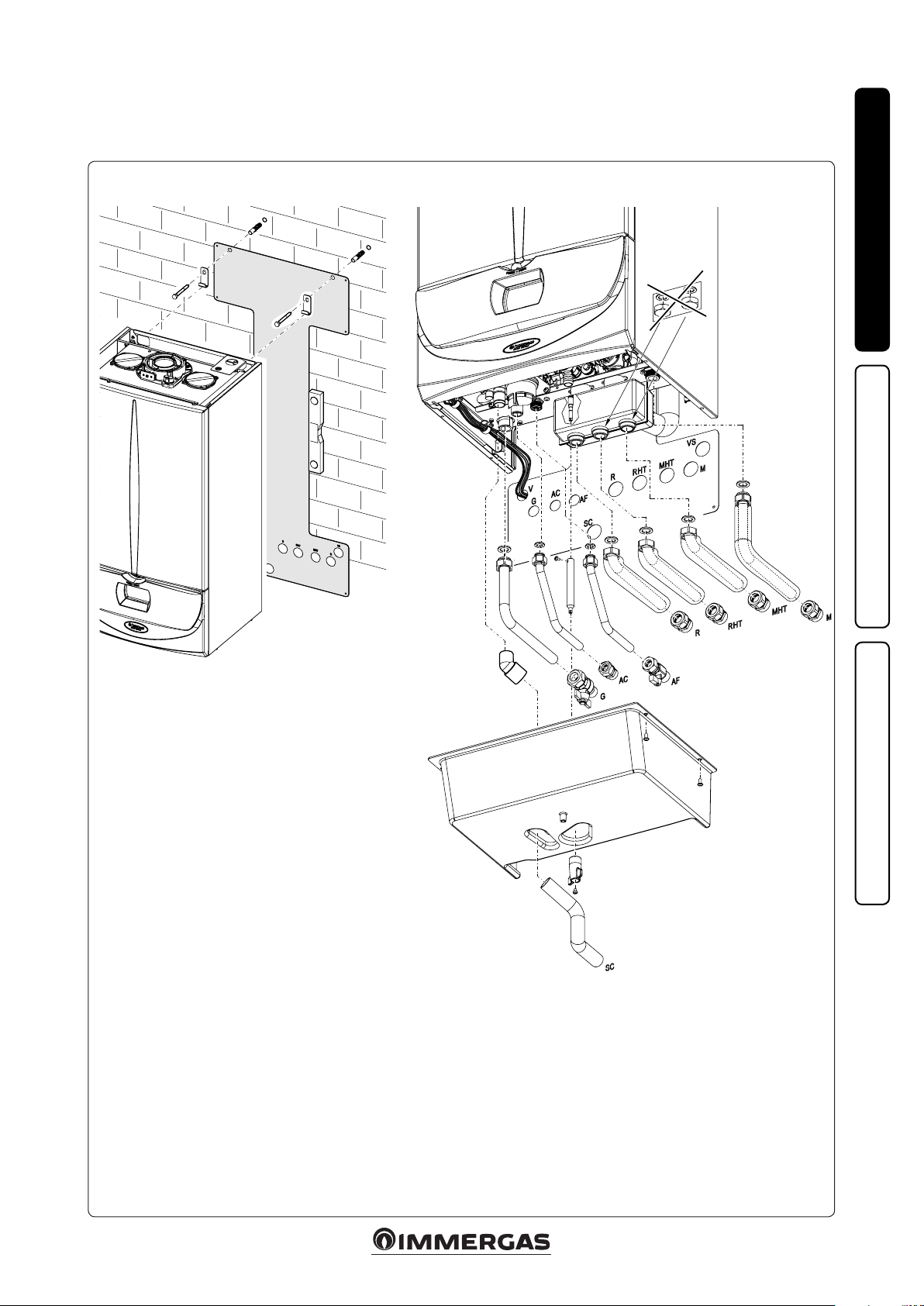
1.4 BOILER CONNECTION UNIT.
e connection unit comes as standard with
the boiler.
INSTALLERUSER
e kit includes:
N°2 - adjustable expansion bolts
N°2 - boiler support hooks
N° 1 - Gas connection pipe Ø 18 (G)
N° 2 - Domestic water pipe 1/2” (AF - AC)
N° 3 - System pipe 3/4” (R - RHT - MHT)
N° 1 - System ow pipe 3/4” (M)
N° 4 - Insulating sheath for system pipes (R - RHT - MHT - M)
N° 1 - Gas valve 1/2" (G)
N° 1 - Ball valve 1/2" (AF)
N° 1 - Telescopic tting 1/2” (AC)
N° 4 - Telescopic tting 3/4” (R - RHT - MHT - M)
N° 1 - Rubber tting for condensate drainage (SC)
N° 1 - Condensate drainage corrugated pipe (SC)
N° 1 - Extension for lling valve
N° 1 - Filling valve
N° 1 - Condensation collection tray
Gaskets, screws and seal O-Ring
MAINTENANCE TECHNICIAN
Key:
V - Electrical connection
G - Gas supply
AC - Domestic hot water outlet
AF - Domestic cold water inlet
SC - Condensate drain (minimum internal diameter Ø 13 mm)
VS - Safety valve drain
RHT - Return to heat pump
MHT - Flow from heat pump
M - System ow
R - System return
1-3
7
Page 8

1.5 GAS CONNECTION.
Our boilers are designed to operate with methane
gas (G20) and LPG. Supply pipes must be the
same as or larger than the 1/2”G boiler tting.
Before connecting the gas line, carefully clean
inside all the fuel feed system pipes to remove
any residue that could impair boiler eciency.
Also make sure the gas corresponds to that for
which the boiler is prepared (see boiler data
name plate). If dierent, the appliance must be
converted for operation with the other type of
gas (see converting appliance for other gas types).
INSTALLERUSER
The dynamic gas supply (methane or LPG)
pressure must also be checked according to the
type used in the boiler, which must comply with
the technical standards in force, as insucient
levels can reduce generator output and cause
malfunctions.
Ensure correct gas cock connection. e gas supply pipe must be suitably dimensioned according
to current regulations in order to guarantee correct gas ow rate to the burner even in conditions
of maximum generator output and to guarantee
appliance eciency (technical specications).
e coupling system must conform to technical
standards in force.
Fuel gas quality. e appliance was designed
to operate with combustible gas free of impurities; otherwise it is advisable to t special lters
upstream of the appliance to restore the purity
of the fuel.
Storage tanks (in case of supply from LPG
depot).
- New LPG storage tanks may contain residual
inert gases (nitrogen) that degrade the mixture
delivered to the appliance casing functioning
anomalies.
- Due to the composition of the LPG mixture,
layering of the mixture components may occur
during the period of storage in the tanks. is
can cause a variation in the heating power of
the mixture delivered to the appliance, with
subsequent change in its performance.
1.6 HYDRAULIC CONNECTION.
Attention: in order not to void the condensa-
tion module warranty, before making the boiler
connections, carefully wash the heating system
(pipes, radiators, etc.) with special pickling or
descaling products to remove any deposits that
could compromise correct boiler operation.
A chemical treatment of the thermal system water is required, in compliance with the technical
standards in force, in order to protect the system
and the appliance from deposits (e.g., lime scale),
slurry or other hazardous deposits.
Water connections must be made in a rational
way. The boiler safety valve outlet must be
connected to a draining funnel. Otherwise, the
manufacturer declines any responsibility in case
of ooding if the drain valve cuts in.
Attention: Immergas declines all liability in the
event of damage caused by the inclusion of automatic lling that is not its own brand.
In order to meet the system requirements established by the technical regulation in force in
relation to the pollution of drinking water, we
recommend installing the IMMERGAS antibackow kit to be used upstream of the cold
water inlet connection of the boiler. It is also
recommended that the heat transfer uid (e.g.
water + glycol) entered in the primary circuit
of the boiler (heating circuit), complies with the
local regulations in force.
Attention: to preserve the duration and the efciency features of the appliance, in the presence
of water whose features can lead to the deposit of
scale, installation of the “polyphosphate dispenser”
kit is recommended.
Condensate drain. To drain the condensate
produced by the appliance, it is necessary to
connect to the drainage system by means of acid
condensate resistant pipes, with an internal Ø of
at least 13 mm. e system connecting the appliance to the drainage system must be carried out
in such a way as to prevent freezing of the liquid
contained in it. Before appliance ignition, ensure
that the condensate can be correctly removed.
Aer rst ignition, check that the drain trap is
lled with condensate (para. 1.20). Also, comply
with national and local regulations on discharging waste waters.
Condensate collection tray drainage. e boiler
in the lower part is equipped with a tting for
draining condensate which may possibly form
due to the circulation of chilled water. Before
appliance start-up, ensure that an excessive production of condensate can be expelled properly.
MAINTENANCE TECHNICIAN
8
Page 9
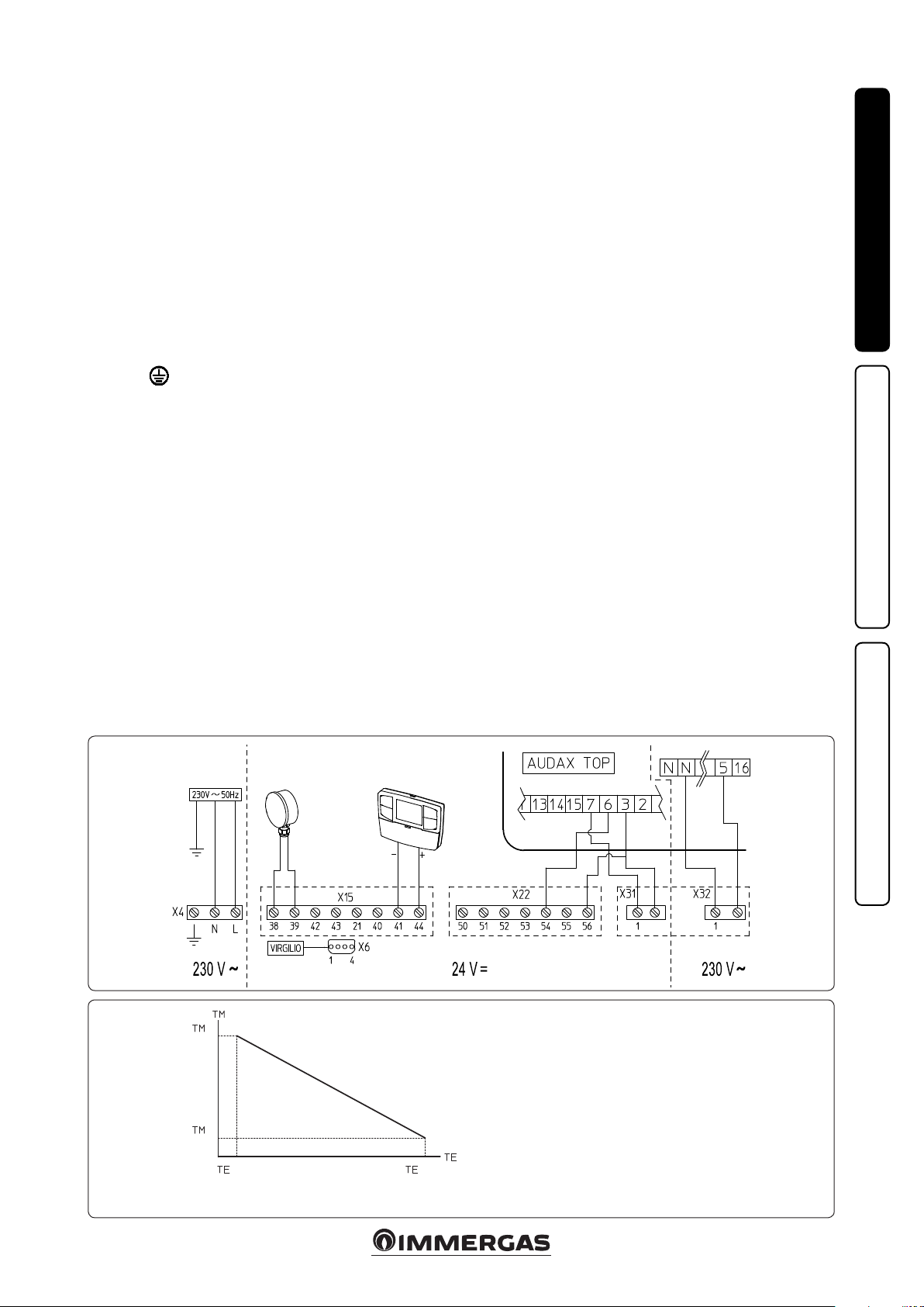
1.7 ELECTRIC CONNECTION.
e appliance has an IPX5D protection degree,
electrical safety of the appliance is reached only
when it is connected properly to an ecient
earthing system as specied by current safety
standards.
Attention: Immergas S.p.A. declines any responsibility for damage or physical injury caused by
failure to connect the boiler to an ecient earth
system or failure to comply with the reference
standards.
Also ensure that the electrical installation
corresponds to maximum absorbed power
specications as shown on the boiler data-plate.
Boilers are supplied complete with an “X” type
power cable without plug. e power supply
cable must be connected to a 230V ±10% / 50Hz
mains supply respecting L-N polarity and earth
connection;
, this network must also have a
multi-pole circuit breaker with class III overvoltage category.
To protect from possible dispersions of DC
voltage one must provide a type A dierential
safety device.
When replacing the power supply cable, contact
a qualied rm (e.g. the Authorised Aer-Sales
Technical Assistance Service). e power cable
must be laid as shown (Fig. 1-3).
In the event of mains fuse replacement on the
P.C.B., use a 3.15A quick-blow fuse. For the main
power supply to the appliance, never use adapters, multiple sockets or extension leads.
• Comando Amico Remoto remote control
electrical connection V2 (CARV2). e boiler
only functions if connected to the Comando
V2
Amico Remoto remote control
per standard with the boiler. e CAR
, supplied as
V2
must
be connected to the + and - IN clamps and to
clamps 44 and 41 on the P.C.B. (in boiler) observing the polarity and using the connection
cable that comes out of the boiler and which is
appropriately marked (Fig. 1-4). Connection
with the wrong polarity prevents the CAR
from operating although without damaging
it. e connection to the boiler is made using
wires with a minimum section of 0.50 mm
and maximum section of 2.5 mm2 and with a
maximum length of 50 metres.
• External temperature probe electrical connection. e boiler only works if it is connected
to the external temperature probe supplied
as per standard with the boiler. Refer to the
relative instruction sheet for positioning of
the external probe. e probe allows to automatically decrease the maximum system ow
temperature when the outside temperature
increases, in order to adjust the heat supplied to
the system according to the change in external
temperature. e correlation between system
ow temperature and external temperature
is determined by the parameters set in menu
“M5” under item “P66” according to the curves
represented in the diagram (Fig. 1-5). e electric connection of the external probe must be
made on clamps 38 and 39 on the boiler P.C.B.
(Fig. 1-4).
• Heat pump electrical connection. e boiler
can be combined with an Immergas heat pump
which must be connected to the boiler as shown
in the wiring diagram (Fig. 1-4).
One must congure some parameters on the
heat pump remote panel:
“Assistance Menu -> Zone Denition”:
Remote control enabling: NO
Room thermostat enabling: SI
V2
- “Zone Set Point” menu
Set mandata riscaldamento
2
Set mandata rarescamento
Set the ow parameters according to your
requirements.
N.B.: hot/cold and on/o request of the heat
pump will be managed by the boiler and not
from the heat pump's remote panel.
Congure the boiler parameters as indicated in
paragraph “circuit board programming” (Par.
3.9).
Important: it is mandatory to prepare separate
lines with dierent supply voltage; it is essential
to separate the low voltage connections from the
230 V ones. All boiler pipes must never be used
for earthing the electrical or telephone system.
Ensure elimination of this risk before making the
boiler electrical connections.
INSTALLERUSER
1-4
1-5
MAX
MIN
TM-MAX/MIN = Selected ow temp. range.
TE = External temperature.
MAINTENANCE TECHNICIAN
EXTERNAL PROBE
Correction law of the ow temperature depend-
ing on the external temperature and user
adjustments of the central heating temperature.
MAXMIN
9
Page 10
1.8 IMMERGAS FLUE SYSTEMS.
Immergas supplies various solutions separately
from the boilers regarding the installation of
air intake terminals and ue exhaust, which are
fundamental for boiler operation.
Attention: the boiler must be installed exclusively with an original Immergas “Green
Range” inspectionable air intake device and
fumes extraction system made of plastic, as
required by the regulations in force.
e plastic pipes cannot be installed outdoors,
INSTALLERUSER
for tracts longer than 40 cm, without suitable
protection from UV rays and other atmospheric agents.
is system can be identied by an identication mark and special distinctive marking
bearing the note: “only for condensing boilers”.
• Resistance factors and equivalent lengths. Each
ue component has a Resistance Factor based
on experimental tests and specied in the table
below. e Resistance Factor for individual
components is independent from the type of
boiler on which it is installed and has a dimensionless size. It is however, conditioned by the
temperature of the uids that pass through the
pipe and therefore, varies according to applications for air intake or ue exhaust. Each single
component has a resistance corresponding to
a certain length in metres of pipe of the same
diameter; the so-called equivalent length,
can be obtained from the ratio between the
relative Resistance Factors. All boilers have an
experimentally obtainable maximum Resistance
Factor equal to 100. e maximum Resistance
Factor allowed corresponds to the resistance
encountered with the maximum allowed pipe
length for each type of Terminal Kit. This
information allows calculations to be made to
verify the possibility of setting up various ue
congurations.
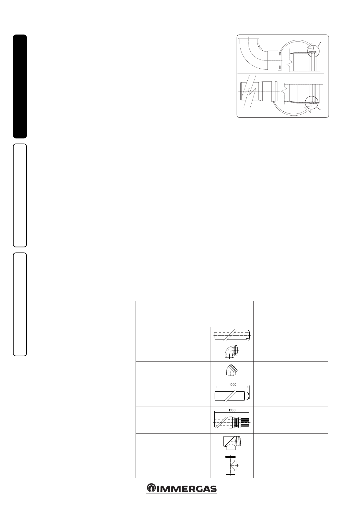
• Positioning the gaskets (black) for “green
range” ue systems. Position the gasket correctly (for bends and extensions) (Fig. 1-6):
- gasket (A) with notches, to use for bends;
- gasket (B) without notches, to use for exten-
sions;
N.B.: if component lubrication (already car-
ried out by the manufacturer) is not sucient,
remove the residual lubricant using a dry cloth,
then to ease tting coat the parts with talc, supplied in the kit.
MAINTENANCE TECHNICIAN
• Coupling extension pipes and concentric
elbows. To install push-tting extensions with
other elements of the ue, proceed as follows:
Install the concentric pipe or elbow with the
male side (smooth) on the female side (with lip
seal) to the end stop on the previously installed
element in order to ensure sealing eciency of
the coupling.
Attention: if the exhaust terminal and/or
concentric extension pipe needs shortening,
consider that the internal duct must always
protrude by 5 mm with respect to the external
duct.
• N.B.: for safety purposes, do not obstruct the
boiler intake/exhaust terminal, even temporaril y.
• N.B.: when installing horizontal pipes, a minimum inclination of 3% must be maintained and
a section clip with pin must be installed every
3 metres.
1.9 TABLES OF RESISTANCE FACTORS
AND EQUIVALENT LENGTHS.
TYPE OF DUCT
Concentric pipe Ø 80/125 m 1
Concentric bend 90° Ø 80/125
1-6
Resistance
Factor
(R)
2.1
3.0
(A)
(B)
Equivalent length
in m of concentric
pipe Ø 80/125
1
1.4
Concentric bend 45° Ø 80/125
Terminal complete with concentric
horizontal intake-exhaust Ø 80/125
Terminal complete with concentric
vertical intake-exhaust Ø 80/125
Concentric bend 90° Ø 80/125 with
inspection
Stub pipe with inspection Ø 80/125
10
2.1
2.8
3.6
3.4
3.4
1
1.3
1.7
1.6
1.6
Page 11
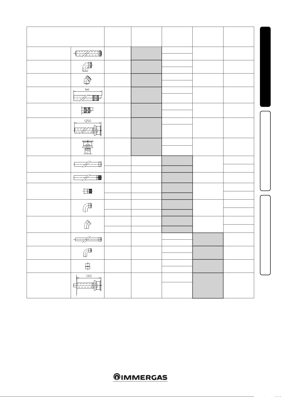
TYPE OF DUCT
Resistance
Factor
(R)
Equivalent length
in m of concentric
pipe Ø 60/100
Equivalent
length in metres
of pipe Ø 80
Equivalent length
in metres of pipe
Ø 60
Equivalent length
in m of concentric
pipe Ø 80/125
Concentric pipe Ø 60/100
m 1
Concentric bend 90° Ø
60/100
Concentric bend 45° Ø
60/100
Terminal complete with
concentric horizontal
intake-exhaust Ø 60/100
Concentric horizontal
intake- exhaust terminal
Ø 60/100
Terminal complete with
concentric vertical intakeexhaust Ø 60/100
Concentric vertical intakeexhaust terminal Ø 60/100
Pipe Ø 80 m 1
Complete intake terminal
Ø 80 m 1
Intake terminal Ø 80
Exhaust terminal Ø 80
Bend 90° Ø 80
Bend 45° Ø 80
Pipe Ø 60 m 1 for ducting
Bend 90° Ø 60 for ducting
Reduction Ø 80/60
Terminal complete with
exhaust
vertical Ø 60 for ducting
Intake and
Exhaust 6.4
Intake and
Exhaust 8.2
Intake and
Exhaust 6.4
Intake and
Exhaust 15
Intake and
Exhaust 10
Intake and
Exhaust 16.3
Intake and
Exhaust 9
Intake 0.87 m 0.1 Intake m 1.0
Exhaust 1.2 m 0.2 Exhaust m 1.0
Intake 3 m 0.5 Intake m 3.4 Exhaust m 0.9 m 1.4
Intake 2.2 m 0.35 Intake m 2.5
Exhaust 1.9 m 0.3 Exhaust m 1.6
Intake 1.9 m 0.3 Intake m 2.2
Exhaust 2.6 m 0.4 Exhaust m 2.1
Intake 1.2 m 0.2 Intake m 1.4
Exhaust 1.6 m 0.25 Exhaust m 1.3
Exhaust 3.3 m 0.5
Exhaust 3.5 m 0.55
Intake and
Exhaust 2.6
Exhaust 12.2 m 1.9
m 1
m 1.3
m 1
m 2.3
m 1.5
m 2.5
m 1.4
m 0.4
Intake m 7.3
Exhaust m 5.3
Intake m 9.4
Exhaust m 6.8
Intake m 7.3
Exhaust m 5.3
Intake m 17.2
Exhaust m 12.5
Intake m 11.5
Exhaust m 8.3
Intake m 18.7
Exhaust m 13.6
Intake m 10.3
Exhaust m 7.5
Intake 3.8
Exhaust 2.7
Intake 4.0
Exhaust 2.9
Intake m 3.0
Exhaust m 2.1
Intake m 14
Exhaust m 10.1
Exhaust m 1.9 m 3.0
Exhaust m 2.5 m 3.9
Exhaust m 1.9 m 3.0
Exhaust m 4.5 m 7.1
Exhaust m 3.0 m 4.7
Exhaust m 4.9 m 7.7
Exhaust m 2.7 m 4.3
Exhaust m 0.4
Exhaust m 0.6
Exhaust m 0.8
Exhaust m 0.5
Exhaust m 1.0 m 1.5
Exhaust m 1.1 m 1.6
Exhaust m 0.8 m 1.2
Exhaust m 3.7 m 5.8
INSTALLERUSER
m 0.4
m 0.5
m 1
m 0.9
m 0.9
m 1.2
m 0.5
0.7
MAINTENANCE TECHNICIAN
11
Page 12
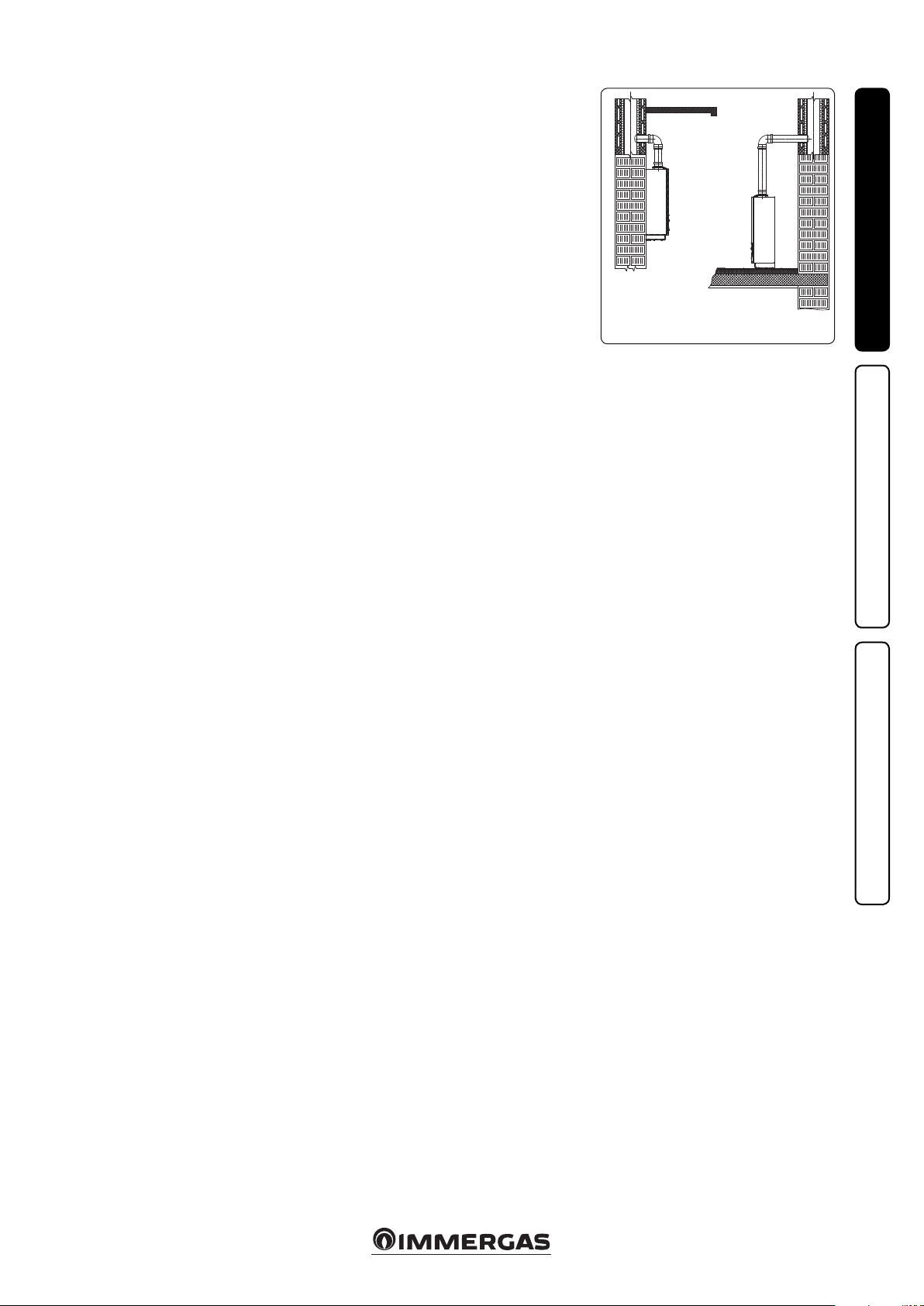
1.10 OUTDOOR INSTALLATION IN
PARTIALLY PROTECTED AREA.
N.B.: a partially protected location is one in which
the appliance is not exposed to the direct action of
the weather (rain, snow, hail, etc..).
is type of installation is only possible when
permitted by the laws in force in the appliance's
country of destination.
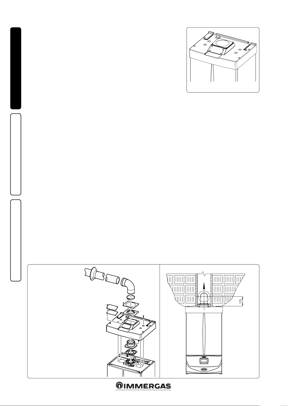
• Conguration type B, open chamber and
forced draught.
Using the special coverage kit one can achieve
INSTALLERUSER
direct air intake (Fig. 1-7) and fumes exhaust in
a single ue or directly outside. In this conguration it is possible to install the boiler in a partially
protected place. In this conguration the boiler
is classied as type B
With this conguration:
- air intake takes place directly from the envi-
ronment in which the appliance is installed
(outside);
- the fumes exhaust must be connected to its own
single ue (B23) or ducted directly outside via
a vertical terminal for direct exhaust (B53) or
via an Immergas ducting system (B53).
The technical regulations in force must be
respected.
• Coverage kit assembly (Fig. 1-8). Remove
the two plugs and the gaskets present from
the two lateral holes with respect to the central
one. Now cover the right intake hole using the
relevant plate, xing it onto the le side using
the 2 previously-removed screws. Install the
Ø 80 outlet ange on the central hole of the
boiler, taking care to insert the gasket supplied
with the kit and tighten by means of the screws
provided. Install the upper cover, xing it using
the 4 screws present in the kit, positioning the
relevant gaskets. Engage the 90° Ø 80 bend
with the male end (smooth) in the female end
(with lip seal) of the Ø 80 ange unit until it
stops. Introduce the gasket, making it run along
the bend. Fix it using the sheet steel plate and
tighten by means of the straps present in the
kit, making sure to block the 4 gasket aps. Fit
the male end (smooth) of the exhaust terminal
.
23
into the the female end of the bend 90° Ø 80,
making sure that the relevant wall sealing plate
is already tted; this will ensure hold and joining of the elements making up the kit.
Max. length of exhaust duct. e ue pipe (both
vertical or horizontal) can be extended to a max.
length of 30 linear metres.
• Coupling of extension pipes. To install push-
tting extensions with other elements of the
ue, proceed as follows: Couple the pipe or
elbow with the male side (smooth) in the female side (with lip seal) to the end stop on the
previously installed element. is will ensure
sealing eciency of the coupling.
• Conguration without cover kit in a partially
protected location (type C boiler)
By leaving the side plugs tted it is possible
to install the appliance externally without the
cover kit. Installation takes place using the
Ø60/100, Ø 80/125 and separator Ø 80/80
concentric intake/ exhaust kits. Refer to the
paragraph relative to indoor installation. In
this conguration the upper cover kit guarantees additional protection for the boiler. It is
recommended but not compulsory.
1-7
MAINTENANCE TECHNICIAN
e cover kit includes:
N° 1 ermoformed cover
N°1 Gasket clamping plate
N°1 Gasket
N°1 Gasket tightening strap
N°1 Intake hole covering plate
e terminal kit includes:
N° 1 Gasket
N° 1 Discharge ange Ø 80
N° 1 Bend 90° Ø 80
N° 1 Drain pipe Ø 80
N° 1 Wall sealing plate
12
1-8
1-9
Page 13
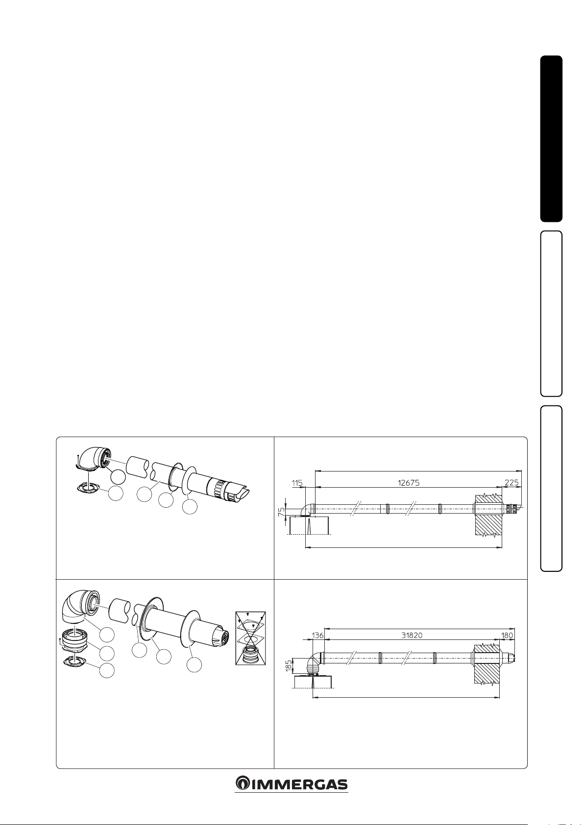
1.11 CONCENTRIC HORIZONTAL KIT
INSTALLATION.
Type C configuration, sealed chamber and
fan assisted.
e position of the terminal (in terms of distances from openings, overlooking buildings,
floor, etc.) must be in compliance with the
regulations in force.
is terminal is connected directly to the outside
of the building for air intake and ue exhaust. e
horizontal kit can be installed with the rear, right
side, le side or front outlet. For installation with
frontal outlet, one must use the xing plate and
a concentric bend coupling in order to ensure
sucient space to carry out the tests required
by law upon commissioning.
• External grid. Both the Ø 60/100 and Ø 80/125
intake/exhaust terminal, if properly installed, is
pleasant to look at on the outside of the building. Make sure that the external silicone wall
sealing plate is properly inserted in the wall.
N.B.: for proper system operation the terminal
with grid must be installed correctly ensuring
that, the "high" indication on the terminal is
observed during installation.
Horizontal intake-exhaust kit Ø 60/100 Kit
assembly (Fig. 1-10): install the bend with ange
(2) on the central hole of the boiler, positioning
gasket (1) with the circular projections downwards in contact with the boiler flange, and
tighten using the screws present in the kit. Fit
the Ø 60/100 (3) concentric terminal pipe with
the male side (smooth) to the female side of the
bend (2) up to the end stop; making sure that the
internal and external wall sealing plate have been
tted, this will ensure sealing and joining of the
elements making up the kit.
• Extensions for Ø 60/100 horizontal kit (Fig.
1-11). e kit with this conguration can be
extended up to a max. 12.9 horizontal m in-
cluding the terminal with grid and excluding
the concentric bend leaving the boiler. is
conguration corresponds to a resistance factor
of 100. In this case the special extensions must
be requested.
Immergas also provides a Ø 60/100 simplied
terminal, which in combination with its extension kits allows you to reach a maximum extension of 11.9 metres.
Horizontal intake-exhaust kit Ø 80/125 Kit
assembly (Fig. 1-12): to install the kit Ø 80/125
one must use the anged adapter kit in order
to install the ue system Ø 80/125. Install the
anged adaptor (2) on the central hole of the
boiler, positioning gasket (1) with the circular
projections downwards in contact with the boiler
ange, and tighten using the screws contained in
the kit. Engage the bend (3) with the male side
(smooth) to the end stop on the adapter (1). Fit
the Ø 80/125 (5) concentric terminal pipe with
the male side (smooth) to the female side of the
bend (4) (with lip seals) up to the end top; making
sure that the internal (6) and external wall sealing
plate (7) have been tted, this will ensure sealing
and joining of the elements making up the kit.
• Extensions for horizontal kit Ø 80/125 (Fig.
1-13). e kit with this conguration can be
extended up to a max. length of 32 m, including the terminal with grid and excluding the
concentric bend leaving the boiler. If additional components are assembled, the length
equivalent to the maximum allowed must be
subtracted. In this case the special extensions
must be requested.
INSTALLERUSER
2
1
3
4
e kit includes:
N° 1 - Gasket (1)
N° 1 - Concentric bend Ø 60/100 (2)
N° 1 - Int./exhaust concentric terminal Ø 60/100 (3)
N° 1 - Internal wall sealing plate (4)
N° 1 - External wall sealing plate (5)
5
3
2
1
e adaptor kit includes:
N° 1 - Gasket (1)
N° 1 - Adaptor Ø 80/125 (2)
e Kit Ø 80/125 includes:
1-12
4
5
6
N° 1 - Concentric bend Ø 80/125
a 87°
N° 1 - Int./exhaust concentric termi-
nal Ø 80/125 (4)
N° 1 - Internal wall sealing plate (5)
N° 1 - External wall sealing plate
(6)
e remaining kit components must
not be used
(3)
C
13
C
13
Max. 12900 mm)
Max. 12790 mm)
MAINTENANCE TECHNICIAN
1-10
C
13
Max. 32000 mm)
Max. 31956 mm)
1-11
C
13
1-13
13
Page 14
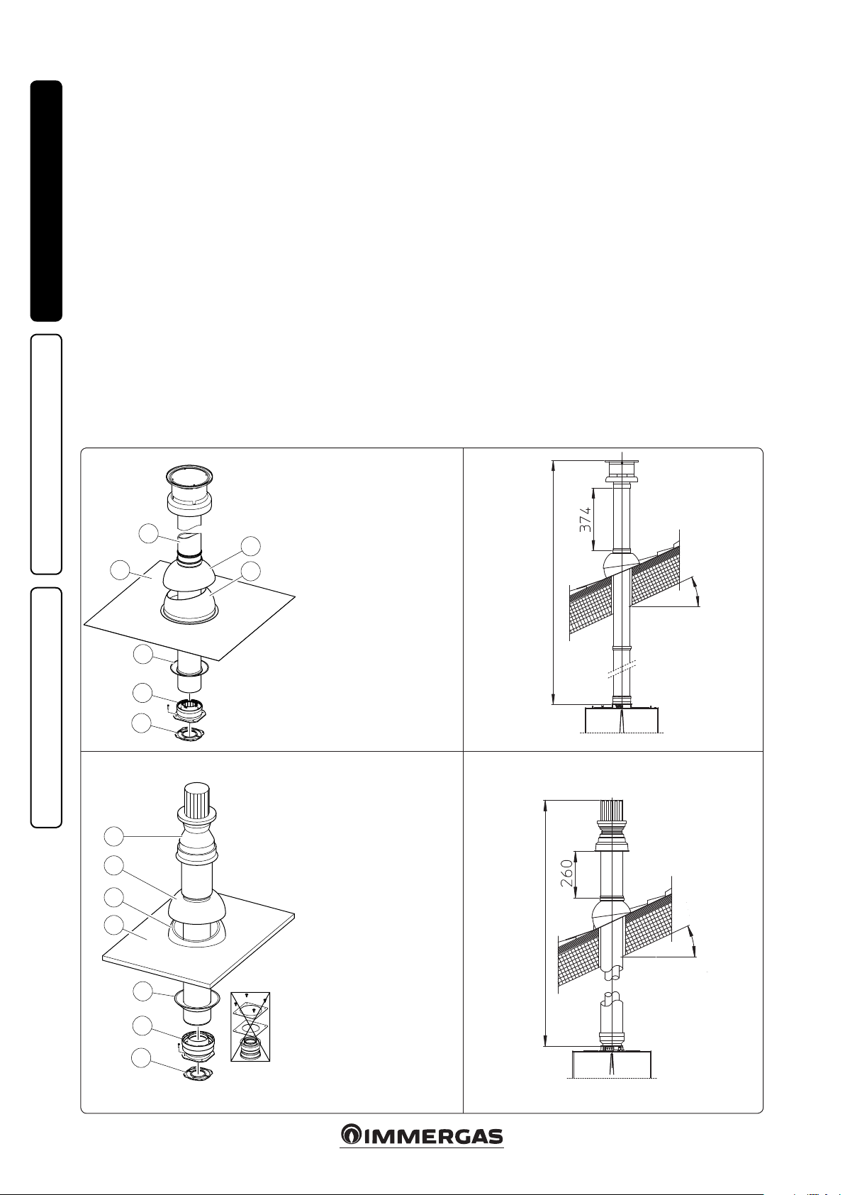
1.12 CONCENTRIC VERTICAL KIT
INSTALLATION.
Type C configuration, sealed chamber and
fan assisted.
Concentric vertical intake and exhaust kit. is
vertical terminal is connected directly to the outside of the building for air intake and ue exhaust.
N.B.: the vertical kit with aluminium tile enables
installation on terraces and roofs with a maximum slope of 45% (approx 25°) and the height
between the terminal cap and half-shell (374 mm
INSTALLERUSER
for Ø 60/100 and 260 mm for Ø 80/125) must
always be observed.
Vertical kit with aluminium tile Ø 60/100.
Kit assembly (Fig. 1-14): install the concentric
ange (2) on the central hole of the boiler, positioning gasket (1) with the circular projections
downwards in contact with the boiler ange, and
tighten using the screws contained in the kit.
Installation of the fake aluminium tile: replace
the tiles with the aluminium sheet (4), shaping
it to ensure that rainwater runs o. Position
the xed half-shell (6) on the aluminium tile
and insert the intake-exhaust pipe (5). Fit the
Ø 60/100 (3) concentric terminal pipe with the
male side (5) (smooth) into the ange (2) up to
the end stop; making sure that the wall sealing
plate has been tted (3), this will ensure sealing
and joining of the elements making up the kit.
NOTE: when the boiler is installed in areas where
very cold temperatures can be reached, a special
anti-freeze kit is available that can be installed as
an alternative to the standard kit.
• Extensions for vertical kit Ø 60/100 (Fig. 1-15).
e kit with this conguration can be extended
to a max. straight vertical length of 14.4 m,
including the terminal. This configuration
corresponds to a resistance factor of 100. In
this case specic extensions must be requested.
Vertical kit with aluminium tile Ø 80/125.
Kit assembly (Fig. 1-16): to install the kit Ø
80/125 one must use the anged adapter kit in
order to install the ue system Ø 80/125. Install
the anged adaptor (2) on the central hole of the
boiler, positioning gasket (1) with the circular
projections downwards in contact with the boiler
ange and tighten using the screws contained
in the kit. Installation of the fake aluminium
tile: replace the tiles with the aluminium sheet
(4), shaping it to ensure that rainwater runs o.
Position the xed half-shell (5) on the aluminium
tile and insert the intake-exhaust pipe (7). Fit the
Ø 80/125 concentric terminal pipe with the male
side (smooth) to the female side of the adapter (1)
(with lip gaskets) up to the end stop; making sure
that the wall sealing plate (3) has been tted, this
will ensure sealing and joining of the elements
making up the kit.
• Extensions for vertical kit Ø 80/125 (Fig. 1-17).
e kit with this conguration can be extended
up to a max. length of 32 m including the terminal. If additional components are assembled,
the length equivalent to the maximum allowed
must be subtracted. In this case specic extensions must be requested.
MAINTENANCE TECHNICIAN
1-14
1-15
C
33
5
4
3
2
1
7
6
5
4
3
7
6
e Kit includes:
N° 1 - Gasket (1)
N° 1 - Female concentric ange (2)
N° 1 - Wall sealing plate (3)
N° 1 - Aluminium tile (4)
N° 1 - Int./exhaust concentric pipe Ø
60/100 (5)
N° 1 - Fixed half-shell (6)
N° 1 - Mobile half-shell (7)
e adaptor kit includes:
N° 1 - Gasket (1)
N° 1 - Adaptor Ø 80/125 (2)
e Kit Ø 80/125 includes:
N° 1 - Wall sealing plate (3)
N° 1 - Aluminium tile (4)
N° 1 - Fixed half-shell (5)
N° 1 - Mobile half-shell (6)
N° 1 - Int./exhaust concentric
pipe Ø 80/125 (7)
e remaining kit components
must not be used
Max. 45%
Max. 14400 mm)
C
1-171-16
33
Max. 45%
Max. 32000 mm)
C
33
C
33
2
1
14
Page 15

1.13 SEPARATOR KIT INSTALLATION.
Type C configuration, sealed chamber and
fan assisted.
Separator kit Ø 80/80. is kit allows air to come
in from outside the building and the fumes to exit
from the chimney or ue through divided ue
exhaust and air intake pipes. Combustion products are expelled from pipe (S) (in plastic, so as
to resist acid condensate). Air is taken in through
duct (A) for combustion (this is also in plastic).
e intake pipe (A) can be installed either on the
right or le hand side of the central exhaust pipe
(S). Both ducts can be routed in any direction.
• Kit assembly (Fig. 1-18): install ange (4) on
the central hole of the boiler, positioning gasket
(1) with the circular projections downwards
in contact with the boiler ange, and tighten
using the hex screws with at tip contained in
the kit. Remove the at ange present in the
lateral hole with respect to the central one (according to needs) and replace it with the ange
(3), positioning the gasket (2) already present in
the boiler and tighten using the supplied selfthreading screws. Fit the male end (smooth) to
the bends (5) in the female end of the anges
(3 and 4). Fit the intake terminal (6) with the
male side (smooth) in the female side of the
bend (5) up to the end stop, ensuring that the
internal and external wall sealing plates are
tted. Fit the exhaust pipe (9) with the male
side (smooth) to the female side of the bend
(5) up to the end stop; making sure that the
internal wall sealing plate has been tted, this
will ensure sealing and joining of the elements
making up the kit.
• Installation clearances (Fig. 1-19). e minimum installation clearance measurements of
the Ø 80/80 separator terminal kit have been
stated in some limit conditions.
• Extensions for separator kit Ø 80/80. The
maximum vertical straight length (without
bends) that can be used for Ø 80 intake and
exhaust pipes is 41 metres, regardless from
whether they are used for intake or exhaust.
e maximum horizontal straight length (with
bend in suction and in exhaust) that can be
used for Ø 80 intake and exhaust pipes is 36
metres, regardless from whether they are used
for intake or exhaust.
N.B.: to favour the removal of possible condensate forming in the exhaust pipe, tilt the pipes
towards the boiler with a minimum slope of
1.5% (Fig. 1-20).
INSTALLERUSER
C53* - C
5
5
7
S
9
4
1
e kit includes:
N° 1 - Exhaust gasket (1)
N° 1 - Flange seal gasket (2)
N° 1 - Female intake ange (3)
N° 1 - Female drain ange (4)
* to er complete C53 conguration also provide for a roof discharge termi-
nal.
6
7
8
A
3
2
N° 2 - Bend 90° Ø 80 (5)
N° 1 - Intake terminal Ø 80 (6)
N° 2 - Internal wall sealing plates (7)
N° 1 - External wall sealing plate (8)
N° 1 - Drain pipe Ø 80 (9)
1-191-18
83
C
43
MAINTENANCE TECHNICIAN
C
83
minimum slope 1.5%
1-20
15
Page 16

1.14 ADAPTOR C9 KIT INSTALLATION.
is kit allows an Immergas boiler to be installed
in "C
" conguration, with combustion air intake
93
directly from the sha where the ue gas exhaust
is, obtained by means of a ducting system.
System composition.
e system must be combined with the following
components (sold separately) to be functional
and complete:
- kit C93 Ø 100 or Ø125 version
- ducting kit Ø 60 or Ø 80
INSTALLERUSER
- fumes exhaust kit Ø 60/100 or Ø 80/125 congured according to the installation and type
of boiler.
Kit Assembly.
- Mount the components of kit "C9" on the door
(A) of the ducting system (Fig. 1-22).
- (Version Ø 125 only) mount the anged adaptor (11) interposing the concentric gasket (10)
on the boiler, tting it with the screws (12).
- Mount the ducting system as described in the
relative instructions sheet.
- Calculate the distances between the boiler drain
and the bend of the ducting system.
- Prepare the boiler ue system, making sure that
the internal pipe of the concentric kit is tted
properly in the bend of the ducting system
(quota "X" g. 1-23), while the external pipe
must be tted on the adaptor until it stops (1).
N.B.: to encourage the removal of possible
condensate forming in the exhaust pipe, tilt
the pipes towards the boiler with a minimum
slope of 1.5%.
- Mount the cover (A) complete with adaptor (1)
and caps (6) on the wall and assemble the ue
system to the ducting system.
N.B.: (version Ø 125 only) before assembly
check the gaskets are in the right position. In
the event component lubrication (already carried out by the manufacturer) is not sucient,
remove the residual lubricant using a dry cloth,
then to ease tting coat the parts with common
or industrial talc.
Once all components have been assembled properly, the exhaust fumes will be expelled via the
ducting system; the combustion air for normal
boiler operation will be aspirated directly by the
sha (Fig. 1-23).
Technical data.
- e dimensions of the shas must ensure a
minimum gap between the outer wall of the
smoke duct and the inner wall of the sha: 30
mm for circular section shas and 20 mm in
the event of a square section sha (Fig. 1-21).
- Maximum 2 changes of direction are allowed
on the vertical section of the ue system with
a maximum clearance angle of 30° with respect
to the vertical.
- e maximum vertical extension using a Ø 60
ducting system is 13 m, the maximum extension includes 1 bend Ø 60/10 at 90°, 1 m of
horizontal pipe 60/100, 1 90° ducted bend Ø
60 and the roof terminal for ducting.
To determine the C
tions other than that described (Fig. 1-23)
one must consider that 1 metre of ducted pipe
according to the indications described has a
resistance factor equal to 4.9.
- e maximum vertical extension using a Ø 80
ducting system is 28 m, the maximum extension includes 1 adapter 60/100 to 80/125, 1 87°
bend Ø 80/125, 1 m of horizontal pipe 80/125,
1 90° ducted bend Ø 80 and the roof terminal
for ducting.
To determine the C93 ue system in congura-
tions other than that described (Fig. 1-23) one
must consider the following pressure drops:
- 1 m of concentric pipe Ø 80/125 = 1 m of
ducted pipe;
- 1 87° bend = 1.4 m of ducted pipe;
Consequently one must subtract the equivalent
length of the part added to the 28 m available.
ue system in congura-
93
1-21
A
B
Kit composition:
Ref. Qty Description
MAINTENANCE TECHNICIAN
1 1 Door adaptor Ø 100 or Ø 125
2 1 Door gasket made of neoprene
3 4 Screws 4.2 x 9 AF
4 1 Hex headed screw M6 x 20
5 1 Flat nylon washer M6
6 2 Door hole closure metal-sheet plate
7 1 Plug gasket made of neoprene
8 1 Toothed washer M6
9 1 Nut M6
10 1 (kit 80/125) Concentric gasket Ø 60-100
11 1 (kit 80/125) Flanged adapter Ø 80-125)
12 4 (kit 80/125) Hex headed screws M4 x 16 slotted
- 1 (kit 80/125) Bag of lubricating talc
Supplied separately:
Ref. Qty Description
A 1 Ducting kit door
plug
1
4
Rigid Ø 80
ducting (A)
mm
86 126 146
Flexible Ø 80
ducting (A)
mm
90 130 150
2
3
6
5
SHAFT
(B) mm
SHAFT
(B) mm
7
SHAFT
(C) mm
SHAFT
(C) mm
A
6
8
9
1-22
Rigid Ø 60
ducting (A)
mm
66 106 126
A
C
SHAFT
(B) mm
Installation drawings key:
Unique identication of the component in
1
the kit
Identication of the component not supplied
in this kit
A
12
SHAFT
(C) mm
3
3
12
11
10
16
Page 17

C
93
X
C
53
INSTALLERUSER
1.15 DUCTING OF FLUES OR
TECHNICAL SLOTS.
Ducting is an operation through which, via
the introduction of one or more relevant pipes,
one achieves a system for the evacuation of the
combustion products of a gas appliance, made up
from the coupling of an existing or new ducting
pipe with a chimney, ue or technical slot (also
in new buildings) (Fig. 1-24). Ducting requires
ducts declared to be suitable for the purpose by
the manufacturer, following the installation and
user instructions, provided by the manufacturer
and the requirements of the standards in force.
Immergas ducting system. e Ø 60 rigid and
Ø 80 exible “Green Range” ducting systems must
only be used for domestic use and with Immergas
condensing boilers.
In any case, ducting operations must respect
the provisions contained in the standard and in
current technical regulations. e instructions in
the project or technical report must likewise be
followed, in cases provided for by the standard
and current technical regulations. e system or
components of the system have a technical life
complying with current standards, provided that:
- it is used in average atmospheric and environ-
mental conditions, according to current regulations (absence of fumes, dusts or gases that can
alter the normal thermophysical or chemical
conditions; existence of temperatures coming
within the standard range of daily variation,
etc.).
- Installation and maintenance must be per-
formed according to the indications supplied
by the manufacturer and in compliance with
the provisions in force.
- e max. possible length of the Ø 60 exible
ducting vertical section is equal to 22 m. is
length is obtained considering the complete
Ø 80 exhaust terminal, 1m of Ø 80 pipe in
exhaust, two 90° Ø 80 bends at boiler outlet.
1-23
- e max. possible length of the Ø 80 exible
ducting vertical section is equal to 30 m. is
length is obtained considering the complete
exhaust terminal, 1m of Ø 80 pipe in exhaust,
two 90° Ø 80 bends at boiler outlet for connecting to the ducting system and two direction
changes of the exible hose inside the chimney/
technical slot.
- e maximum possible length of the Ø 80 rigid
ducting vertical section is equal to 30 m. is
length is obtained considering the complete
Ø 80 exhaust terminal, 1m of Ø 80 pipe in exhaust, two 90° Ø 80 bends on the boiler outlet.
1.16 CONFIGURATION TYPE B, OPEN
CHAMBER AND FAN ASSISTED FOR
INDOORS.
e appliance can be installed inside buildings
in 23 or B53 mode; in this case, all technical rules
and national and local regulations in force, must
be complied with.
- type B open chamber boilers must not be
installed in places where commercial, artisan
or industrial activities take place, which use
products that may develop volatile vapours
or substances (e.g. acid vapours, glues, paints,
solvents, combustibles, etc.), as well as dusts
(e.g. dust deriving from the working of wood,
coal nes, cement, etc.), which may be harmful for the components of the appliance and
jeopardise operation.
- in B23 and B53 conguration, the boilers must
not be installed in bedrooms, bathrooms or in
studio ats unless otherwise provided by local
regulations.
- e installation of appliances in B23 and B53 congurations are only recommended outdoors (in
a partially-protected place) or in places that
are not lived in and which are permanently
ventilated.
e suitable kit referred to in paragraph 1.10
must be used for installation.
1-24
1.17 FLUE EXHAUST TO FLUE/CHIMNEY.
Flue exhaust does not necessarily have to be
connected to a branched type traditional ue.
e ue exhaust, for boiler clots installed in C
configuration, can be connected to a special
LAS type multiple ue. For B congurations,
exhaust is only allowed into individual chimney
or directly into the external atmosphere via a
relevant terminal, unless otherwise provided by
local regulations. e multiple ues and the combined ues must also only be connected to type C
appliances of the same type (condensing), having
nominal heat inputs that do not dier by more
than 30% less with respect to the maximum that
can be attached and powered by the same fuel.
e thermo-uid dynamic features (ue ow
rate, % of carbon dioxide, % humidity etc....) of
the appliances attached to the same multiple ues
or combined ues, must not dier by more than
10% with respect to the average boiler attached.
Multiple and combined ues must be specially
designed according to the calculation method
and requirements of the technical standards in
force, by a professionally qualied company (e.g.
EN 13384). Chimney or ue sections for connection of the ue exhaust pipe must comply with
requisites of technical standards in force.
MAINTENANCE TECHNICIAN
17
Page 18

1.18 FLUES, CHIMNEYS, CHIMNEY POTS
AND TERMINALS.
e ues, chimneys and chimney pots for the
evacuation of combustion products must be in
compliance with applicable standards. Chimneys
and roof-installed exhaust terminals must comply with the outlet height and with the distance
from technical volumes set forth by the technical
standards in force.
Positioning the wall ue exhaust terminals. e
wall ue exhaust terminals must:
INSTALLERUSER
- be installed on external perimeter walls of the
building;
- be positioned according to the minimum dis-
tances specied in current technical standards.
Combustion products exhaust of natural
draught or fan assisted appliances in open-top
closed environments. In spaces closed on all
sides with open tops (ventilation pits, courtyards etc.), direct combustion product exhaust
is allowed for natural draught or fan assisted gas
appliances with a heat input range from 4 to 35
kW, provided the conditions as per the current
technical standards are respected.
1.19 SYSTEM FILLING.
Once the boiler and the heat pump have been
connected, ll the system via the lling valve (Fig.
1-27 and 2-6). Filling is performed at low speed
to ensure release of air bubbles in the water via
the boiler, heat pump and heating system vents.
e boiler incorporates an automatic vent valve tted on the circulator pump and one on the system
vent tank. Check if the cap is loose. Open the radiator
vent valves.
Close radiator vent valves when only water
escapes from them.
Close the lling cock when the boiler pressure
gauge indicates approx. 1.2 bar.
N.B.: during these operations activate the automatic vent functions featured on the boiler
(active upon initial ignition) and on the heat
pump (see relative instructions booklet). Vent
the boiler circulation pump by loosening the front
cap and keeping the motor running. Tighten the
cap aer the operation.
1.21 GAS SYSTEM STARTUP.
To start up the system, refer to the technical
standard in force.
In particular, for new gas systems:
- open windows and doors;
- avoid presence of sparks or open ames;
- bleed all air from the pipelines;
- check that the internal system is properly sealed
according to the specications set forth by
technical regulations in force.
1.22 BOILER START UP IGNITION.
To commission the boiler (the operations listed
below must only be performed by qualied personnel and in the presence of professionals only):
- check that the internal system is properly sealed
according to the specications set forth by
technical regulations in force;
- make sure that the type of gas used corresponds
to boiler settings;
- Check that there are external factors that may
cause the formation of fuel pockets;
- switch the boiler on and check correct ignition;
- make sure that the gas ow rate and relevant
pressure values comply with those given in the
manual (Par. 3.20);
- ensure that the safety device intervenes in the
event of gas supply failure and check the relative
intervention time;
- check the intervention of the main switch
located upstream from the boiler and in the
boiler;
- check that the intake/exhaust concentric terminal (if tted) is not blocked.
e boiler must not be started up even if only
one of the checks should be negative.
1.20 CONDENSATE TRAP FILLING.
On rst lighting of the boiler combustion products may come out the condensate drain; aer a
few minutes’ operation check that this no longer
occurs. is means that the trap is lled with
MAINTENANCE TECHNICIAN
condensate to the correct level preventing the
passage of combustion products.
18
Page 19

1.23 CIRCULATION PUMP.
e boilers are supplied with 2 circulator pumps,
both equipped with speed regulator.
ese settings are suitable for most systems.
• Boiler circulator pump. e boilers are sup-
plied with a variable speed circulator pump.
When the boiler operates in heating mode, the
pump speed is dened according to the “P57”
parameter setting in the M5 menu (Par. 3.9), in
domestic hot water mode the circulator pump
always runs at maximum speed.
During the heating stage the Auto and Fixed
operating modes are available.
NOTE.: the ∆T can be controlled compatibly
with the characteristics of the central heating
system and of the boiler.
• Auto: automatic pump speed. In this mode one
can choose between the “Proportional head”
and “Constant ∆T” option.
- Proportional head (∆T = 0): the circulator
speed varies according to the power emitted by the burner, the greater the power the
greater the speed. Within the parameter one
can also adjust the pump operating range,
by setting the maximum speed (adjustable
from 100 % ÷ 30 %) and the minimum speed
(adjustable from 30% to the max. set speed).
- ∆T Constant (∆T = 5 ÷ 25 K): the pump
speed varies to maintain the ∆T constant
between the system ow and return according to set value K. Within the parameter one
can also adjust the pump operating range,
by setting the maximum speed (adjustable
from 100 % ÷ 30 %) and the minimum speed
(adjustable from 30% to the max. set speed).
• Fixed (100 % ÷ 30 %): in this mode, the pump
operates at constant speed, the operating range
is dened between minimum (30 %) and maximum (100 %).
Pump release. If, aer a prolonged period of
inactivity, the circulation pump is blocked,
unscrew the front cap and turn the motor sha
using a screwdriver. Take great care during this
operation to avoid damage to the motor.
• System circulator pump. e system circulator
pump controls the room heating or cooling requests downstream of the hydraulic manifold.
In fact, the pump is equipped with electronic
control that allows to set advanced functions..
For proper operation one must select the most
suitable type of operation for the system and
select a speed between 2 and 7.
- Constant head program (P C) (4 fig.
1-25). e circulator pump maintains the
pressure level (head) constant as the system
heat demand decreases (ow rate reduction).
With these settings, the circulator pump is
suitable for all oor systems where all the
circuits must be balanced for the same drop
in head. One can select the power level from a
minimum one to a maximum one by turning
the selector switch clockwise in the relative
power scale.
- Proportional head program (P V) (3 g.
1-25). is allows the pressure level (head)
to be proportionally reduced as the system
heat demand decreases (flow rate reduction). anks to this function, the electric
power consumption of the circulator pump
is reduced further: the energy (power) used
by the pump decreases according to the pressure level and ow rate. With this setting, the
pump guarantees optimal performance in
most heating systems, proving particularly
suitable in single-pipe and two-pipe installations. Any noise of the water ow in the pipes,
valves and radiators is eliminated by reducing
the head. Optimal conditions for thermal
comfort and acoustic well-being. One can select the power level from a minimum one to a
maximum one by turning the selector switch
counterclockwise on the relative power scale.
Adjustments. Turn the selector and set it on
the desired curve to adjust the circulator pump.
Automatic vent function (1 g. 1-25). e
circulator pump is equipped with a function
that activates its operation for 10 minutes,
alternating the speed between minimum and
maximum, so that the air contained in the circulator pump is expelled by the air vent valve.
Diagnostics in real time: a light ring (2 g.
1-25) supplies, with dierent colours, information relating to the circulator pump operating
status, see table below.
1-25
Key:
1 - Automatic vent mode
operation
2 - Light ring to indicate the
operating status
3 - Proportional head opera-
tion
4 - Constant head operation
5 - Operating mode selector
switch
INSTALLERUSER
LED Description Diagnostics Cause Remedy
Green (on) Normal functioning
Green
(fast ashing)
Red (on)
Green (ashing)
Red (ashing) Circulator pump blocked
LED (o) circulator pump not working electronics not powered
Automatic vent in operation
Abnormal situation
Circulator pump working but
stationary
e circulator pump vents for
10 minutes
e circulator pump restarts
once the abnormal situation
has been solved
the circulator pump cannot
restart automatically due to an
anomaly
Air in circulator pump
a) voltage out of range
(160 ÷ 253V)
b) circulator pump tempera-
ture high
check the circulator pump
a) circulator pump not con-
nected
b) LED damaged
c) electronics damaged
If the circulator pump requires
the automatic vent function
oen, one must adjust the operating mode properly.
a) check power supply
b) check temperature of room
and of the water contained
in the system
if the problem persists replace
the circulator pump
a) check the electrical connec-
tions
b) check that the circulator
pump is working
c) replace the circulator pump
19
MAINTENANCE TECHNICIAN
Page 20

Head available to the system.
INSTALLERUSER
Constant head (ΔP C).
Head (kPa)Head (kPa)
Proportional head (ΔP V).
1-26
A
A
Speed 7
B
Speed 2
Circulator pump absorbed power (W)Circulator pump absorbed power (W)
Flow rate (l/h)
Key:
A = Head available at speed 2 ÷ 7
B = Power absorbed by the system
circulator pump (dotted area)
Speed 7
1.24 KITS AVAILABLE ON REQUEST.
• System shut-off valve kits with or without
inspection lter (on request). e boiler is
designed for installation of system interception
cocks to be placed on ow and return pipes
of the connection assembly. is kit is very
useful for maintenance because it allows to
MAINTENANCE TECHNICIAN
empty just the boiler without having to empty
the entire system. Moreover, the version with
lter preserves the functioning characteristics
of the boiler thanks to its inspectionable lter.
• Kit with two motorised areas (on request). In
the event one wants to divide the thermal system in two areas to interlock them separately
with independent adjustments, on request Immergas can supply the kit with two motorised
areas.
B
Speed 2
Flow rate (l/h)
• Polyphosphate dispenser kit (on request). e
polyphosphate dispenser reduces the formation
of lime-scale and preserves the original heat
exchange and domestic hot water production
conditions. e boiler is prepared for application of the polyphosphate dispenser kit.
• Cover kit (on request). If installed outdoors in a
partially protected place with direct air intake,it
is compulsory to mount the appropriate top
protection cover for the correct functioning
of the boiler and to protect it from adverse
weather conditions.
e above-mentioned kits are supplied complete
with instructions for assembly and use.
20
Page 21

1.25 BOILER COMPONENTS.
1-27
INSTALLERUSER
Key:
1 - System lling valve
2 - Condensate drain trap
3 - Gas valve
4 - Domestic hot water probe
5 - Domestic hot water ow rate adjuster
6 - Safety thermostat
7 - Gas nozzle
8 - Delivery probe
9 - Venturi
10 - Detection electrode
11 - System expansion vessel
12 - Air intake pipe
13 - Condensation module
14 - Manual air vent valve
15 - Negative signal pressure point
16 - Positive signal pressure point
MAINTENANCE TECHNICIAN
17 - Sample points (air A) - (ue gas F)
18 - Flue safety thermostat
19 - Heat exchanger safety thermal fuse
20 - System vent tank air valve
21 - System vent tank
22 - Ignition electrodes
23 - Fan
24 - Igniter
25 - Burner
26 - Return probe
27 - System pressure switch
28 - Vent valve
29 - System probe
30 - Boiler circulator pump
31 - system circulator pump
32 - DHW heat exchanger
33 - 3-way valve (motorised)
34 - 3 bar safety valve
35 - System draining valve
36 - hydraulic manifold
21
Page 22

USE AND MAINTENANCE
2
INSTRUCTIONS
2.1 CLEANING AND MAINTENANCE.
Attention: to preserve the boiler's integrity
and keep the safety features, performance and
reliability, which distinguish it, unchanged over
time, you must execute maintenance operations
on a yearly basis in compliance with what is stated
in the relative point at “annual check and maintenance of the appliance”, in compliance with
national, regional, or local standards in force.
INSTALLERUSER
2.2 GENERAL WARNINGS.
Never expose the wall-mounted boiler to direct
vapours from a cooking surface.
Use of the boiler by unskilled persons or children
is strictly prohibited.
For safety purposes, check that the concentric
air intake/flue exhaust terminal (if fitted), is
not blocked.
If temporary shutdown of the boiler is required,
proceed as follows:
a) drain the heating system if antifreeze is not
used;
b) shut-o all electrical, water and gas supplies.
In the case of work or maintenance to structures
near ducting or devices for ue extraction and the
relative accessories, switch o the appliance and
on completion of the operations make sure that
an authorised company veries the eciency of
the ducting or the devices.
Never clean the appliance or connected parts
with easily ammable substances.
Never leave containers or ammable substances
in the same environment as the appliance.
• Attenzione: the use of components involving
use of electrical power requires some fundamental rules to be observed:
- do not touch the appliance with wet or moist
parts of the body; do not touch when barefoot;
- never pull electrical cables or leave the appliance exposed to weathering (rain, sunlight,
etc.);
- the appliance power cable must not be replaced by the user;
- if the cable is damaged, switch o the appliance and solely contact an authorised
company to replace it;
- if the appliance is not to be used for a certain
period, disconnect the main power switch.
N.B.: the temperatures indicated by the display
have a tolerance of +/- 3°C due to environmental
conditions that cannot be attributed to the boiler.
At the end of its service life the appliance must
not be disposed of like normal household waste
nor abandoned in the environment, but must
be removed by a professionally authorised
company. Contact the manufacturer for disposal
instructions.
2.3 CONTROL PANEL.
Key:
- Stand-by - On Button
A - Summer ( ) and winter ( ) operating mode button
B - Not used on this model
C - Reset (RESET) / exit menu (ESC) button
D - Menu entry button (MENU)/ data conrmation (OK) button
1 - Domestic hot water temperature selector
2 - Domestic hot water temperature set
3 - Central heating temperature selector
4 - Central heating temperature set
4 - Presence of anomalies
MAINTENANCE TECHNICIAN
6 - Display of boiler functioning status
8 - Flame presence symbol and relative power scale
9 and 7 - Primary heat exchanger outlet water temperature
10 - Boiler in stand-by
11 - Boiler connected to remote control (Optional)
12 - Functioning in summer mode
13 - Antifreeze function in progress
14 - Functioning in winter mode
15 - Not used on this model
16 - Connection to external tools for technician
17 - Display of menu items
18 - Functioning with external temperature probe active
19 - Display of data conrmation or menu access
20 and 7 - Outside temperature display
with external probe connected (optional)
21 - Display of reset or exit menu request
22 - Chimney sweep function in progress
23 - Boiler manometer
24 - Multi-function display
25 - Functioning in winter mode
26 - Heat pump operation in progress
22
2-1
Page 23

2.4 DESCRIPTION OF FUNCTIONING
STATES
Below nd a list of boiler functioning states that
appear on the multifunction display (24) by
means of the indicator (6) with a brief description. Refer to the instruction book for a complete
explanation.
Display (6) Description of functioning states
SUMMER
WINTER
CHILLER
DHW ON
CH ON
COOLING
F3
CAR OFF Remote Control o.
F4
F5
P33
STOP
ERR xx
SET
SET
SET
F8
Summer functioning mode without request in progress.
Boiler in stand-by for domestic hot water request.
Winter functioning mode without request in progress.
Boiler in stand-by for domestic hot water or central heating request.
Cooling operating mode without requests in progress.
Boiler awaiting domestic hot water request and heat pump awaiting room cooling.
Domestic hot water mode in progress.
Boiler functioning, domestic hot water heating in progress.
Central heating mode in progress.
Boiler or heat pump in operation, room heating is in progress.
Cooling mode in progress.
Heat pump in operation, room cooling is in progress.
Antifreeze mode in progress.
Boiler functioning to restore the minimum safety temperature against boiler freezing.
Postventilation in progress.
Fan in function aer a request for domestic hot water or central heating in order to evacuate residual ue gas.
Postcirculation in progress.
Pump in function aer a request for domestic hot water or central heating in order to cool the primary circuit.
With Remote Control in block, the boiler works equally in central heating mode. (Can be activated through the “M3” menu. It allows
to activate the central heating even if the Remote Control is out of order).
Reset attempts nished
Wait for 1 hour to re-acquire 1 attempt.
(Error code 08).
Anomaly present with relative error code.
e boiler does not work. (see troubleshooting paragraph).
When the domestic hot water temperature selector switch is turned (1 Fig. 2-1) it displays the control status of the domestic hot
water temperature in progress.
When the central heating temperature selector switch is turned (1 Fig. 2-1) it displays the control status of the boiler ow temperature for room central heating.
In presence of the external probe it replaces the “SET” item.
e value that appears is the correction of the ow temperature with respect to the functioning curve set by the external probe. See
OFFSET on external probe graphics (Fig. 1-5).
System deaeration in progress.
During this phase, which lasts 18 hours, the boiler circulator pump is started at preset intervals, thus allowing deaeration of the
central heating system.
INSTALLERUSER
23
MAINTENANCE TECHNICIAN
Page 24

2.5 USING THE BOILER.
Attention: the boiler only works properly if it is
connected to the CAR
V2
, to the external probe supplied as standard and combined with the Immergas
heat pump supplied separately.
Consequently, all controls and adjustments are requested to the CAR
while the Standby button “
V2
(refer to the relative manual),
”, Reset button “C”
and the menu access button “D” on the boiler still
remain active.
Before ignition make sure the central heating sys-
INSTALLERUSER
tem is lled with water and that the manometer
(23) indicates a pressure of 1 - 1.2 bar;
Open the gas valve upstream of the boiler; it is
then possible to switch the boiler on.
When the boiler is switched o, the boiler display
only indicates the Stand-by symbol (10) the
V2
CAR
will show the connection error symbol
“ERR>CM” the CAR
V2
is in any case still powered
without losing the stored programs by pressing
the button (
) one switches the boiler on.
Connection to the CARV2 is detected automatically and the boiler display indicates the symbol
).
(
Once the boiler is switched on, the display indicates all operating information
• Summer ( ): in this mode the boiler only
operates for domestic hot water heating.
During domestic hot water heating, “DHW
ON” appears on the display (24) on the status
indicator (6) and at the same time as the burner
ignites, the ame presence indicator switches
on (8) with the relative power scale and the indicator (9 and 7) with the instantaneous outlet
temperature from the primary heat exchanger.
Summer mode operation with domestic hot
water heating
• Winter ( ): in this mode the boiler func-
tions both for heating domestic hot water and
heating the environment. Depending on the
climatic conditions and on the set-point, the
control electronics establish whether it is more
convenient to use the boiler, the heat pump or
both to heat the environment.
- Room heating with boiler: during the request
“CH ON” appears on the display (24) on the
status indicator (6) and at the same time as
the burner ignites the ame presence indicator switches on (8) with the relative power
scale and the indicator (9 and 7) with the
instantaneous outlet temperature from the
boiler. During the heating stage, if the water
temperature is sucient to heat the system,
the boiler can operate just with the activation
of water circulation.
Winter operation mode with room central
heating with boiler
2-3
- Room heating with heat pump: during the
request “CH ON” appears on the display (24)
on the status indicator (6) and at the same
time as the heat pump starts-up the indicator
switches on (26) as well as the indicator (7)
with the instantaneous outlet temperature
from the boiler.
Winter operation mode with room central
heating with heat pump
• External probe operation (part. 18). The
boiler flow temperature for room central
heating is managed by the external probe depending on the external temperature measured
(Parag. 1.7 and par. 3.9 under item “P66”). One
can modify the operation curve by acting on
the central heating selector of the CAR
V2
(see
relative manual).
From this moment the boiler functions automatically. With no demand for heat (central heating
or domestic hot water production) the boiler
goes to “standby” function, equivalent to the
boiler being powered without presence of ame.
N.B.: it is possible that the boiler may start-up
automatically if the antifreeze function is activated (13). Moreover, the boiler can function
for a brief period of time aer a withdrawal of
domestic hot water in order to take the domestic
hot water temperature back into temperature.
• Air conditioning ( ): in this mode the boiler
works both for domestic hot water heating as
well as cooling, the boiler manages solely the
system circulator pump and the heat pump for
room cooling starts to work depending on what
has been set on the CARV2.
During cooling “COOLING” appears on the
display (24) on the status indicator (6) and at
the same time when the heat pump starts-up
the indicator switches on (26) as well as the
indicator (7) with the instantaneous outlet temperature from the boiler. e ow temperature
will be xed at the “cooling set point” (SPC)
value set on the heat pump.
Cooling mode operation with heat pump
MAINTENANCE TECHNICIAN
2-2
• Stand-by ( ): Attention: with the boiler in
2-4
stand-by mode, hot water cannot be produced
and the following safety functions are not ensured: pump anti-block device, antifreeze and
three-way anti-block device and the cooling
function is also inhibited.
• CAR O: with CARV2 o, the boiler display
indicates the “CAR OFF” operating status;
the boiler safety functions remain in any case
active.
2-5
24
Page 25

2.6 TROUBLESHOOTING.
e boiler signals any anomalies via the ashing
symbol (5) along with the “ERRxx” indication on
the indicator (6) where “xx” corresponds to the
error code described in the following table. e
error code will be displayed on the remote panel
via the same numeric code represented according
to the following example: CAR
V2
= Exx.
Error
Code
(1) If the shutdown or fault persists, contact an authorised company (e.g. Authorised Technical Aer-Sales Service).
(2) e boiler does not start, the heat pump stays active to satisfy the room heating and cooling requests
(3) e heat pump does not start, the boiler stays active to satisfy the room heating and domestic hot water production requests
Anomaly signalled Cause Boiler status / Solution
In the event of request of room central heating or domestic hot
01 No ignition block
Safety thermostat
block (overheating),
02
ame control or
fumes thermofuse
anomaly
Contacts resistance
04
block
05 Flow probe anomaly e board detects an anomaly on the ow NTC probe. e boiler does not start (1) (2).
Domestic hot water
06
probe anomaly
08 Maximum N° of reset Number of allowed resets that have already performed.
Insucient system
10
pressure
15 Conguration error
16 Fan anomaly is occurs if the fan has a mechanical or electrical fault. Press the Reset button (1) (2)
20 Parasite ame block
23 Return probe anomaly e board detects an anomaly on the system return NTC probe. e boiler does not start (1) (2).
Push button control
24
panel anomaly
Insucient circula-
27
tion
IMG Bus communica-
36
tion failure or CAR
absent
Low power supply
37
voltage
38 Loss of ame signal
45 T high
48 System probe anomaly e board detects an anomaly on the system ow NTC probe. (1) (3)
High temperature
49
block on return probe
water production, the boiler does not switch on within the preset
time. Upon appliance commissioning or aer extended downtime,
it may be necessary to eliminate the block.
During normal operation, if a fault causes excessive overheating
internally, the boiler goes into overheating block.
Safety thermostat fault (overheating) or ame control anomaly. e boiler does not start (1) (2).
e board detects an anomaly on the domestic hot water NTC probe.
In this case the antifreeze function is also inhibited
Water pressure inside the central heating circuit that is sucient to
guarantee the correct operation of the boiler is not detected.
If the board detects an anomaly or incongruity on the electric wiring,
the boiler will not start.
is occurs in the event of a leak on the detection circuit or anomaly
in the ame control unit.
e board detects an anomaly on the pushbutton panel.
is occurs if there is overheating in the boiler due to insucient water
circulating in the primary circuit; the causes can be:
- low system circulation; check that no shut-o devices are closed on
the heating circuit and that the system is free of air (deaerated);
- pump blocked; free the pump.
Communication between the control units is interrupted due to an
V2
anomaly on the boiler control unit or on the IMG Bus. Or CARV2
not connected.
is occurs when the power supply voltage is lower than the allowed
limits for the correct boiler operation.
is occurs when the boiler is ignited correctly and the burner ame
switches o unexpectedly; a new ignition attempt is performed and
if normal conditions are restored, the boiler does not need to be reset
(this fault can be checked in the list of errors in the “M1” menu only).
If the board detects a sudden and unexpected rise in ΔT between
the system ow probe and return probe, the boiler limits the burner
output to prevent damaging the condensation module; when the
correct ΔT has been restored, the boiler resumes normal operation.
is occurs when the heat exchanger return circuit reaches a temperature that is too high.
Press the Reset button (1) (2)
Press the Reset button (1) (2)
In this case the boiler continues to produce
domestic hot water but not with optimal
performance (1)
Attention: the anomaly can be reset 5 times
consecutively, aer which the function in
inhibited for at least one hour. One attempt
is gained every hour for a maximum of 5
attempts. By switching the appliance on and
o the 5 attempts are re-acquired.
Check on the boiler pressure gauge (1) that
the system pressure is between 1÷1.2 bar
and restore the correct pressure if necessary.
If normal conditions are restored the boiler
restarts without having to be reset (1) (2).
Press the Reset button (1) (2)
If normal conditions are restored the boiler
restarts without having to be reset (1).
Press the Reset button (1) (2).
e boiler does not satisfy the room heating
and cooling requests (1) (2).
If normal conditions are restored the boiler
restarts without having to be reset (1) (2).
If normal conditions are restored the boiler
restarts without having to be reset (1) (2).
If normal conditions are restored the boiler
restarts without having to be reset (1) (2).
Make sure that water circulates properly in
the boiler and that the three-way valve works
proper ly. Press the Reset button (1) (2).
INSTALLERUSER
MAINTENANCE TECHNICIAN
25
Page 26

Error
Code
INSTALLERUSER
(1) If the shutdown or fault persists, contact an authorised company (e.g. Authorised Technical Aer-Sales Service).
(2) e boiler does not start, the heat pump stays active to satisfy the room heating and cooling requests
(3) e heat pump does not start, the boiler stays active to satisfy the room heating and domestic hot water production requests
Anomaly signalled Cause Boiler status / Solution
External probe miss-
50
ing or faulty
58 Heat pump anomaly
In the event the external probe is not connected or is faulty, the
anomaly is indicated.
In the event of a heat pump anomaly, room heating is ensured by
the boiler. All heat pump functions (room heating and cooling) are
inhibited.
Check the external probe connection (1)
(3).
Check the type of anomaly directly on the
remote panel display (see relative instructions manual).
In the event the heat pump does not feature any anomaly, check that the domestic
hot water inlet probe is working properly
(1) (3).
MAINTENANCE TECHNICIAN
26
Page 27

2.7 PARAMETERS AND INFORMATION
MENU.
By pressing the button "D" it is possible to access
a menu divided into three main parts:
- “M1” information;
- “M3” customisations;
- “M5” congurations: menu reserved to the
Information menu (“M1”). is menu contains the various information relative to boiler functioning:
1st
Button 2nd Level Button 3rd Level Button Description
Level
P11
P12 View the total functioning hours of the boiler
P13 View the number of burner ignitions
D
C
technician and for which a password is required
(See “Maintenance” chapter).
By turning the central heating temperature selector switch (3) scroll through the menu items.
By pressing button “D” access the various levels
of the menu and the choice of parameters is
conrmed. Press button “C” to go back one level.
View the management soware version of the P.C.B. installed in the boiler
INSTALLERUSER
P14
(with optional
external probe
present)
D
M1
C
Customisations Menu (“M3”). This menu
contains all functioning options that can be
customised. (e rst item of the various options
that appears inside the parameter is that selected
by default).
Attention: if the international language is to be
restored (A1), proceed as follows:
- - -
(without external
probe (optional)
P15
P17 View the fan instantaneous rotation percentage speed (in RPM)
P18 View the circulator pump instantaneous speed (in %)
P19
D
C
D
C
P14/A View the current external temperature (if optional external probe present)
P14/B
P14/C
RESET
- press button "D" to enter the conguration
menu.
- turn selector switch "3" to “PERSONAL”.
- press button "D" to conrm.
- turn selector switch "3" to “DAT I”.
- press button "D" to conrm.
- turn selector switch "3" to “LINGUA”.
View the minimum external temperature recorded (if optional external
probe present)
View the maximum external temperature recorded (if optional external
probe present)
D
x
By pressing button “D” the MIN and MAX temperatures are brought to the
select
default value of 25 °C
C
View the value of the domestic hot water ow rate from the ow meter
View the last 5 events that caused boiler shutdown. Indicator (6) shows the
sequential number from 1 to 5 and on indicator (7) the relative error code.
By pressing button "D" repeatedly it is possible to view the functioning
time and the number of ignitions at which the anomaly occurred
- press button "D" to conrm.
- turn selector switch "3" to “A1”.
- press button "D" to conrm.
At this point, the items indicated in the menu
tables appear on the display.
1st
Button 2nd Level Button 3rd Level Button 4th Level Button Description
Level
M3
D
C
P31
P32
P33
RESET
D
C
D
C
D
C
D
x
select
C
AUTO
(Default)
ON e display is always lit up
OFF
P32/B
OFF
(Default)
ON
D
x
select
C
D
C
D
x
select
C
ITALIANO
A1
(Default)
select
e display lights up when the burner is ignited
and when the controls are accessed, it remains on
for 5 seconds aer the last operation performed
e display only lights up when the controls are
accessed and remains on for 5 seconds aer the
last operation performed
D
All descriptions are given in Italian
x
All descriptions are given in alphanumerical
format
C
In winter mode, by activating this function it is
possible to activate the room central heating function even if the eventual Remote Control or TA
are out of service.
By pressing “D”, the customisations are reset, restoring the default values of P31 in “ILL. AUTO”
and P32/B in “ITALIANO” set by default.
27
MAINTENANCE TECHNICIAN
Page 28

3
4
2.8 BOILER SHUTDOWN
Switch the boiler o by pressing the “ ” button, disconnect the onmipolar switch outside of
the boiler and close the gas cock upstream of the
appliance. Never leave the boiler switched on if
le unused for prolonged periods.
2.9 RESTORE CENTRAL HEATING
SYSTEM PRESSURE.
Periodically check the system water pressure.
e boiler pressure gauge should read a pressure
between 1 and 1.2 bar.
INSTALLERUSER
If the pressure falls below 1 bar (with the circuit
cold) restore normal pressure via the valve located
at the bottom of the boiler (Fig. 2-6).
N.B.: close the valve aer the operation.
If pressure values reach around 3 bar the safety
valve may be activated.
In this case, remove water from an air vent valve
of a radiator until 1 bar is reached or ask for assistance from an authorised company.
If frequent pressure drops should occur, ask an
authorised company for assistance to eliminate
the possible system leakage.
2.10 SYSTEM DRAINAGE.
To drain the boiler, use the special draining
valve (Fig. 2-6).
Before draining, ensure that the lling valve is
closed.
2.11 ANTIFREEZE PROTECTION.
e “Magis Victrix ErP” series boiler features
an anti-freeze function that lights the burner
automatically when the temperature falls below
4°C (standard protection up to minimum temperature of -3°C). All information relative to
the anti-freeze protection is stated in Par. 1.3. In
order to guarantee the integrity of the appliance
and the domestic hot water heating system in
zones where the temperature falls below zero,
we recommend the central heating system is
protected using anti-freeze liquid and installation
of the Immergas Anti-freeze Kit in the boiler. In
the case of prolonged inactivity (second case),
we also recommend that:
- disconnect the electric power supply;
- the central heating circuit and boiler domestic
hot water circuit must be drained. In systems
that are drained frequently, lling must be carried out with suitably treated water to eliminate
hardness that can cause lime-scale.
2.12 CASE CLEANING.
Use damp cloths and neutral detergent to clean
the boiler casing. Never use abrasive or powder
detergents.
2.13 DECOMMISSIONING.
In the event of permanent shutdown of the
boiler, contact an authorised company for the
suitable procedures and also ensure the electrical, water and fuel supply lines are shut o and
disconnected.
MAINTENANCE TECHNICIAN
Key:
1 - 3 bar safety valve
2 - Gas cock
3 - Domestic cold water inlet valve
4 - System lling valve
5
5 - System draining valve
1
2
2-6
28
Page 29

BOILER COMMISSIONING
3
INITIAL CHECK
To commission the boiler:
- make sure that the type of gas used corresponds
to boiler settings;
- check connection to a 230V-50Hz power
mains, correct L-N polarity and the earthing
connection;
- make sure the central heating system is lled
with water and that the manometer indicates
a pressure of 1÷1.2 bar.
- check that the heat pump is connected and
powered properly (see relative instructions
manual);
3.1 WIRING DIAGRAM.
3-1
12
11
9
10
4
5
4
8
8
8
6
6
13
11
5
- check that the common parameters between
the heat pump and the boiler are congured
properly;
- switch the boiler on and check correct ignition;
- check the ∆p gas values in domestic hot water
and central heating modes;
- check the CO2 in the fumes at maximum and
minimum ow rate;
- check activation of the safety device in the event
of no gas, as well as the relative activation time;
- check the intervention of the main switch
located upstream of the boiler and in the boiler;
- check that the intake and/or exhaust terminals
are not blocked;
5
5
458867445
4
- ensure activation of all adjustment devices;
- seal the gas ow rate regulation devices (if settings are modied);
- check the production of domestic hot water;
- check sealing eciency of water circuits;
- check ventilation and/or aeration of the installation room where provided.
If even only a single safety check oers a negative
result, do not commission the system.
6
7
INSTALLERUSER
8
7144
13
13
6
8
4
13
11613
Key:
A3 - Integrated P.C.B
A4 - Display board
A7 - Relay P.C.B.
A19 - Relay P.C.B. 2
B1-1 - Boiler ow probe
B1-2 - System ow probe
B2 - Domestic hot water probe
B4 - External probe
B5 - Return probe
B6 - Domestic hot water ow meter
B9 - Domestic hot water inlet probe
CARV2 - Comando Amico Remoto remote
control
V2
E1 - Ignition electrodes
E2 - Detection electrode
E4 - Safety thermostat
E6 - Flue safety thermostat
E13 -
Heat exchanger safety thermofuse
F1 - Phase fuse
G2 - Igniter
K1 - O/On forcing relay
K51 - Central heating / cooling selector
relay
K52 - Anomaly relay
M1-1 - Boiler circulator pump
1
5
4
3
5
7
15
14
15
M1-2 - System circulator pump
M20 - Fan
M30 - ree-way valve
M40 - Domestic ow rate regulator
S5 - System pressure switch
S34 - System supervisor connection
selector
R14 - Boiler conguration resistance
T1 - Low voltage power supply unit
Y1 - Gas valve
4
5
2
5
4
5
4
CH ON
1 - 230 Vac 50 Hz power supply
2 - Status signal
3 - Yellow/green
MAINTENANCE TECHNICIAN
4 - Blue
5 - Brown
6 - Red
7 - White
8 - Black
9 - Central heating
10 - Domestic hot water
11 - Yellow
12 - Purple
13 - Green
14 - Orange
15 - Pink
e connector X6 is for connection to a personal
computer.
e connector X8 is used for soware updating
operations.
Selector S34 denes boiler operation with the
external probe and must always be set = On.
Relays K2 and K3 can be congured.
29
Page 30

3.2 BOILER HYDRAULIC DIAGRAM.
INSTALLERUSER
Key:
1 - Condensate drain trap
2 - Water inlet lter*
3 - Domestic hot water ow meter
4 - Domestic hot water ow rate adjuster
5 - Domestic hot water probe
6 - Gas valve
7 - Gas valve outlet pressure point (P3)
8 - Boiler circulator pump
9 - Vent valve
10 - Venturi positive sign (P2)
11 - Venturi negative sign (P2)
12 - Air/gas Venturi manifold
13 - Fan
14 - Gas nozzle
15 - Detection electrode
16 - Air intake pipe
17 - Condensation module
18 - Manual vent valve
19 - Heat exchanger safety thermal fuse
20 - Air sample point
21 - ∆p gas pressure point
22 - Flue sample point
23 - Fumes hood
24 - Heat exchanger safety thermal fuse
25 - Delivery probe
26 - Safety thermostat
27 - Ignition electrodes
28 - Burner
29 - Condensation module cover
30 - Return probe
31 - System expansion vessel
32 - System draining valve
33 - System pressure switch
34 - DHW heat exchanger
35 - ree-way valve (motorised)
36 - System vent tank air valve
37 - 3 bar safety valve
38 - System vent tank
39 - System lling valve
40 - Hydraulic manifold
41 - System probe
42 - System circulator pump
MAINTENANCE TECHNICIAN
* = Attention: check the presence and
cleanliness of the water inlet lter,
which guarantees the eciency of the
boiler
G - Gas supply
AC - Domestic hot water outlet
AF - Domestic cold water inlet
SC - Condensate drain
RHT - Return to heat pump
MHT - Flow from heat pump
M - System ow
R - System return
3-2
30
Page 31

3.3 INSTALLATION EXAMPLE HYDRAULIC DIAGRAM .
3-3
WATER-DHW NETWORK
INSTALLERUSER
SYSTEM
CENTRAL HEATING
COOLING
Key:
1 - Boiler
2 - External temperature probe
3 -
Comando amico remoto remote control V2 (CARV2)
4 - Heat pump
5 - Heat pump remote panel
3.4 TROUBLESHOOTING.
N.B.: maintenance operations must be carried
out by an authorised company (e.g. Authorised
Aer-Sales Technical Assistance Service).
- Smell of gas. Caused by leakage from gas circuit
pipelines. Check sealing eciency of gas intake
circuit.
- Repeated ignition blocks. No gas, check the
presence of pressure in the network and that
the gas adduction cock is open. Incorrect
adjustment of the gas cock, check the correct
calibration of the gas valve.
- Irregular combustion or noisiness. It may be
caused by: a dirty burner, incorrect combustion
parameters, intake-exhaust terminal not correctly installed. Clean the above components
and ensure correct installation of the terminal,
check correct setting of the gas valve (O-Set
setting) and correct percentage of CO2 in ue
gas.
- Frequent interventions of the overheating
safety thermostat. It can depend on the lack
of water in the boiler, little water circulation
in the system or blocked pump. Check on the
manometer that the system pressure is within
established limits. Check that the radiator
valves are not closed and also the functionality
of the pump.
AC - Domestic hot water outlet
AF - Domestic cold water inlet
RHT - Return to heat pump
MHT - Flow from heat pump
M - System ow
R - System return
- Drain trap clogged. is may be caused by
dirt or combustion products deposited inside.
Check, by means of the condensate drain cap,
that there are no residues of material blocking
the ow of condensate.
- Heat exchanger clogged. is may be caused
by the drain trap being blocked. Check, by
means of the condensate drain cap, that there
are no residues of material blocking the ow of
condensate.
- Noise due to air in the system. Check opening of the special air vent valve cap (Part. 28
Fig. 1-27). Make sure the system pressure and
expansion vessel pre-charge values are within
the set limits; e factory-set pressure values of
the expansion vessel must be 1.0 bar, the value
of system pressure must be between 1 and 1.2
bar.
- Noise due to air inside the condensation
module. Use the manual air vent valve (Part.
14 Fig. 1-27) to eliminate any air present in the
condensation module. When the operation has
been performed, close the manual vent valve.
- System low circulation. Check the boiler,
system and heat pump circulator pumps is
working properly.
- Heat pump not working. Check that the heat
pump is powered and the presence of errors
on the relative control panel (see heat pump
instructions manual).
MAINTENANCE TECHNICIAN
31
Page 32

Gas Valve 8205 Gas Valve 848
P3
+
P1
2
+
12
INSTALLERUSER
1
3
P.C.B.
P1
P3
2
1
Key:
4 - Fuse 3.15 AF
5 - Selector S34: must be set on On
Key:
1 - Gas valve inlet pressure
point
2 - Gas valve outlet pressure
+
+
12
point
3 - O/Set adjustment screw
12 - Outlet gas ow rate regu-
lator
3
3-4
3.5 CONVERTING THE BOILER TO
OTHER TYPES OF GAS.
If the boiler has to be converted to a dierent gas
type to that specied on the data plate, request
the relative conversion kit for quick and easy
conversion.
e gas conversion operation must be carried
out by an authorised company (e.g. Authorised
Technical Aer-Sales Service).
To convert to another type of gas the following
operations are required:
- disconnect the appliance;
- replace the nozzle located between the gas pipe
and gas/air mixing sleeve (Part. 7 Fig. 1-27),
MAINTENANCE TECHNICIAN
taking care to disconnect the appliance during
this operation;
- re-power the appliance;
- calibrate the number of fan revolutions (parag.
3.6):
- adjust the correct air/gas ratio (parag. 3.7);
- seal the gas ow rate regulation devices (if set-
tings are modied);
- after completing the conversion, apply the
sticker, contained in the conversion kit, near
the data nameplate. Using an indelible marker
pen, delete the data relative to the old type of
gas.
ese adjustments must be made with reference
to the type of gas used, following that given in
the table (Par. 3.20).
3.6 CALIBRATION OF NUMBER OF FAN
REVS.
Attention: verication and calibration is neces-
sary, in the case of transformation to other types
of gas, in the extraordinary maintenance phase
with replacement of the PCB air/gas circuit components or in the case of installations with ue
extraction systems, with horizontal concentric
pipe measuring more than 1 metre.
e boiler heat output is correlated to the length
of the air intake and ue exhaust pipes. is
decreases with the increase of pipe length. e
boiler leaves the factory adjusted for minimum
pipe length (1m). It is therefore necessary, especially in the case of maximum pipe extension, to
check the ∆p gas values aer at least 5 minutes
of the burner operating at nominal heat output,
when the temperatures of the intake air and exhaust ue gas have stabilised. Adjust the nominal
and minimum heat output in the domestic hot
water and central heating modes according to
the values in the table (Par. 3.19) using the differential manometers connected to the ∆p gas
pressure points (15 and 16 Fig. 1-27).
Access the congurations menu (Par. 3.9) and
adjust the ignition power “P50”, while within
item “SERVICE” adjust the following parameters:
3-5
- boiler maximum heat output “P62”;
- boiler minimum heat output “P63”;
- maximum central heating output “P64”;
- minimum central heating output “P65”;
Below nd the default settings present on the
boiler:
Magis Victrix ErP
P50 36 % 40%
P62
P63
P64
P65
G20:
5500 (rpm)
G20:
1000 (rpm)
G20:
5000 (rpm)
G20:
1000 (rpm)
LPG:
5000 (rpm)
LPG:
1000 (rpm)
LPG:
4500 (rpm)
LPG:
1000 (rpm)
32
Page 33

3.7 ADJUSTMENT OF THE AIRGAS
RAT IO.
Attention: the CO
be carried out with the casing mounted, while the
verication operations must
2
gas valve calibration operations must be carried
out with the casing open and disconnecting the
boiler from the power supply.
Calibration of the minimum CO
heating power).
(minimum
2
Enter the chimney sweep phase without withdrawing domestic hot water and take the selector switches to minimum (turn them in an
anti-clockwise direction until "0" is seen on the
display). To have an exact value of CO
gases the technician must insert the sampling
in the ue
2
probe to the bottom of the sample point, then
check that the CO2 value is that specied in the
table, otherwise adjust the screw (3 Fig. 3-4) (OSet adjuster). To increase the CO2 value, turn the
adjustment screw (3) in a clockwise direction and
vice versa to decrease it.
Calibration of the maximum CO2 (nominal
central heating power).
On completion of the adjustment of the minimum CO2 keeping the chimney sweep function
active, take the heating selector switch to maximum (turn it in a clockwise direction until “99”
is seen on the display). To have an exact value of
CO2 in the ue gases the technician must insert
the sampling probe to the bottom of the sample
point, then check that the CO2 value is that specied in the table, otherwise adjust the screw (12
Fig. 3-4) (gas ow rate regulator).
To increase the CO2 value one must turn the
adjustment screw (12) clockwise for gas valve
8205 and counterclockwise for gas valve 848 and
vice versa is one wants to decrease it.
At every adjustment variation on the screw 12 it
is necessary to wait for the boiler to stabilise itself
at the value set (about 30 sec.).
3.8 CHECKS FOLLOWING
CONVERSION TO ANOTHER TYPE
OF GAS.
Aer making sure that conversion was carried
out with a nozzle of suitable diameter for the
type of gas used and the settings are made at the
correct pressure, check that the burner ame is
not too high or low and is stable (does not detach
from burner);
N.B.: all boiler adjustment operations must be
carried out by a qualied company (e.g. Authorised Aer-Sales Assistance).
INSTALLERUSER
Magis Victrix ErP
at nominal
CO
2
output
(central heating)
CO2 at minimum
output
(central heating)
G 20 9.50% ± 0.2 8.95% ± 0.2
G 30 12.30% ± 0.2 11.80% ± 0.2
G 31 10.40% ± 0.2 10.00% ± 0.2
MAINTENANCE TECHNICIAN
33
Page 34

3.9 PROGRAMMING THE P.C.B.
e Magis Victrix ErP boiler is set up for possible
programming of several operating parameters.
By modifying these parameters as described
below, the boiler can be adapted according to
specic needs.
Attention: If the international language is to be
restored (A1), see the instructions described in
Par. 2.7 (customisations menu - M3).
By pressing the button "D" it is possible to access
the main menu, divided into three main parts:
INSTALLERUSER
- Information“M1” (See “User” Chapter)
- customisations “M3” (See “User” Chapter)
1st Level 2nd Level Options Description Default value
P50 25 ÷ 50
P53
P54
- “M5” congurations, menu reserved for the
technician and for which a password is required.
To access programming, press button “D”, turn
the heating temperature selector switch (3) and
scroll through the menu items until reaching
“M5”, press button “D”, enter the password and
set the parameters according to requirements.
Listed below are the items in the “F5” menu
with default parameters and possible options
indicated.
M5 menu
(password must be entered)
Set the boiler power in the ignition stage. e value is in percentage
with respect to parameter P62
P53 1
P53 2
P53 3
P54.1
P54.2
P54.3 Displays the temperature read on the return probe - -
Identies the power of the boiler on which the P.C.B. is installed
P53 1 = Not used
P53 2 = 26 kW
P53 3 = 32 kW
Displays the temperature read on the domestic hot water probe on
entry to the boiler
Displays the temperature read on the domestic hot water probe on exit
from the boiler
By turning the central heating temperature selector switch (3) scroll through the menu items.
By pressing button “D” access the various levels
of the menu and the choice of parameters is
conrmed. Press button “C” to go back one level.
(e rst item of the various options that appears
inside the parameter is that selected by default).
Value
set by the
technician
(See par. 3.6)
Equal to boiler
power
- -
- -
Equal to
boiler
power
MAINTENANCE TECHNICIAN
P55
SERVICE
P54.4 Displays the temperature read on the system ow probe - -
AUTO
P57
FIX Fixed circulator pump speed (adjustable between 100% and 54%)
P62 4000 ÷ 5900
P63 900 ÷ 1500
P64 ≤ P62
P65 ≥ P63
P66/A
P66/B
P66
P66/C
P66/D
Displays the central heating ow temperature at which the boiler functions, calculated by the controls active on the system heat adjustment
- DELTA T = 0:proportional head (see parag. 1.23)
- DELTA T = 5 ÷ 25 K: constant ∆T (see par. 1.23)
Set the maximum output depending on the domestic hot water, setting
the speed of the fan (in RPM)
Set the minimum output depending on the domestic hot water, setting
the speed of the fan (in RPM)
Set the maximum output depending on room heating. e value must
be less than or equal to P62
Set the minimum output according to room heating. e value must
be greater than or equal to P63
With the external probe present it denes the minimum ow temperature corresponding to operation with maximum external temperature
(see graph Fig. 1-5) (it can be set between 20°C and 50°C)
N.B.: to continue one must conrm the parameter (press “D” or exit
adjustment “P66” by pressing “C”)
With the external probe present it denes the maximum ow temperature corresponding to operation with minimum external temperature
(see graph Fig. 1-5) (it can be set between 50°C and 85°C)
N.B.: to continue one must conrm the parameter (press “D” or exit
adjustment “P66” by pressing “C”)
With the external probe present it denes at which minimum external
temperature the boiler must operate at the maximum ow temperature
(see graph Fig. 1-5) (can be set between -20°C and 0°C)
N.B.: to continue one must conrm the parameter (press “D” or exit
adjustment “P66” by pressing “C”)
With the external probe present it denes at which maximum external
temperature the boiler must operate at the minimum ow temperature
(see graph Fig. 1-5) (can be set between 5°C and +25°C)
N.B.: to continue one must conrm the parameter (press “D” or exit
adjustment “P66” by pressing “C”)
- -
AUTO
0
(See par. 3.6)
(See par. 3.6)
(See par. 3.6)
(See par. 3.6)
25 °C
55 °C
-5°C
25°C
34
Page 35

M5 menu
(password must be entered)
1st Level 2nd Level Options Description
P67.1
P67
P67.3
P68 0s ÷ 500s
P69 0s ÷ 255s
P70 0s ÷ 840s
P71.1
P71
P71.2
AUTO
P72
OFF
09 L/M
12 L/M
15 L/M
RELE1-0 Relay 1 not used
In winter mode the pump is always powered and so functions continuously
In winter mode the pump is managed by the room thermostat or by the
remote control
In winter mode the pump is managed by the room thermostat or by the
remote control and by the boiler ow probe
e boiler is set to ignite the burner immediately aer a request for central heating. In the case of particular systems (e.g. area systems with motorised thermostatic valves etc.) it could be necessary to delay switch-on
e boiler has an electronic timing device that prevents the burner from
igniting too oen in the central heating phase.
e boiler performs an ignition ramp to arrive from minimum power to
nominal heat output.
OFF domestic hot water “correlated” to the switch-o of the boiler takes
place on the basis of the temperature set using the domestic hot water
adjustment selector switch. Solar function active, if the input domestic
hot water has a sucient temperature the boiler does not switch on
"xed" domestic hot water OFF; the boiler switches o at 65°C.
Solar function deactivated
e boiler allows to set the ow rate adjuster on the various levels.
Auto (automatic functioning, therefore with variable ow rate)
Open (adjuster completely open therefore maximum ow rate available)
09 L/M, 12 L/M and 15 L/M (operation with dened ow)
Default
value
P67.2P67.2
0 seconds
180 seconds
180 seconds
(3 minutes)
P71.2
AUTO
Value
set by the
technician
INSTALLERUSER
SERVICE
RELAY1
RELAY2
RELE1-1 Heat pump control relay; it switches operation from heating to cooling
RELE1-2
RELE1-3
RELE1-4
RELE1-5
RELE2-0 Relay 2 not used
RELE2-1 In a system divided into zones, relay 2 controls the secondary zone
RELE2-2
RELE2-3
RELE2-4
RELE2-5 Function not available on this boiler model
RELE2-6
e relay signals the intervention of a boiler block (Can be coupled to an
external signalling device, not supplied)
e relay signals that the boiler is in heating or cooling request mode (the
status of the system circulator pump is replicated)
(Can be coupled with an external circulator pump, not supplied)
Controls the opening of an external gas valve in concomitance with an
ignition request of the boiler burner
In the event the boiler circulator pump is replaced with a traditional xed
speed circulator pump one must connect the new circulator pump to the
relay board.
e relay signals the intervention of boiler block ( Can be coupled to an
external signalling device, not supplied)
e relay signals that the boiler is in heating or cooling request mode (the
status of the system circulator pump is replicated)
(Can be coupled with an external circulator pump, not supplied)
Controls the opening of an external gas valve in conjunction with an ignition
request of the boiler burner
In the event the boiler circulator pump is replaced with a traditional xed
speed circulator pump one must connect the new circulator pump to the
relay board.
RELE1-1
RELE2-0
MAINTENANCE TECHNICIAN
35
Page 36

INSTALLERUSER
M5 menu
(password must be entered)
1st Level 2nd Level Options Description
RELE3-0 Relay 3 not used
Check the storage tank recirculation pump
(not used on this model)
e relay signals the intervention of boiler block ( Can be coupled to an
external signalling device, not supplied)
e relay signals that the boiler is in heating or cooling request mode (the
status of the system circulator pump is replicated)
(Can be coupled with an external circulator pump, not supplied)
Controls the opening of an external gas valve in concomitance with an
ignition request of the boiler burner
In the event the boiler circulator pump is replaced with a traditional xed
speed circulator pump one must connect the new circulator pump to the
relay board
With S34 = On. If the reading of the external probe is not correct it is possible
to correct it in order to compensate any environmental factors
With S34 = O. Setting not used
Heat pump set point value during the heating mode.
Attention: set the same value selected on the heat pump.
By setting the parameter = 0, the functions relating to the heat pump are
disabled and the boiler can operate normally, without taking into account
the activation delays due to combined operation with the heat pump.
Activation band.
Temperature interval to establish the intervention or non-intervention of
the boiler as integration
Activation delay.
Time interval relating to the activation, disabling and reactivation of the
boiler integrating the heat pump.
MAGIS
RELE3-1
RELE3-2
RELAY3
P76
PAR. 1 0 ÷ 55°C
PAR. 2
PAR. 3 0 ÷ 20’
RELE3-3
RELE3-4
RELE3-5 Function not available on this boiler model
RELE3-6
-15°C ÷
+14°C
CE
20 ÷ 100
(tenths of °C)
Default
value
RELE3-0
0°C
45
50
20
Value
set by the
technician
MAINTENANCE TECHNICIAN
36
Page 37

3.10 CENTRAL HEATING OPERATION IN
COMBINATION WITH THE HEAT
PUMP.
Following a request during the room heating
mode, the electronics decide, according to the
external temperature, whether to activate the
heat pump, or (with cold or high temperatures)
the boiler (g. 3-6):
Boiler and heat pump can even operate simultaneously: in fact, if only the heat pump is active,
but it cannot bring the water to temperature
within a certain time, the boiler starts in parallel.
e boiler electronics select which heat source
to be used according to the combination of
“MAGIS” parameters.
e heating mode is equipped with a timer that
prevents the generators from restarting too frequently. One can modify this value via parameter
“P69”. e heat pump is equipped with its own
timer that that prevents the frequent start-ups,
set at a xed value (3 minutes).
INSTALLERUSER
Set Risc
Set Risc
Max
Max
Funzionamento
55 °C
Min
Min
Exclusive boiler
esclusivo
operation
caldaia
Funzionamento
Heat pump opera-
pompa di calore
tion
Se dopo il tempo di
If aer activa-
attivazione non si
tion time the set
raggiunge la temp.
temperature is not
impostata parte
reached, the boiler
anche la caldaia
also starts
Values Te1 and Te2 are determined by the logic of the boiler board
37
Funzionamento
Heat pump operation
pompa di calore
If aer activation time
Se dopo il tempo di
multiplied by 2 the
attivazione moltiplicato
set temperature is not
per 2 non si raggiunge
reached, the boiler also
la temp. impostata
anche la caldaia
Te2 25Te1-15
starts
parte
External
Temp
temp
esterna
MAINTENANCE TECHNICIAN
3-6
Page 38

3.11 "CHIMNEY SWEEP" FUNCTION.
If this function is activated it takes boiler functioning to the adjustable power of the central
heating selector switch.
In this state all adjustments are excluded and only
the safety thermostat and the limit thermostat
remain active. To activate the chimney sweep
function press the Reset button "C" for 8 to 15
seconds in absence of domestic hot water and
heating requests. Its activation is signalled by
the relative symbol (22 Fig. 2-1). is function
allows the technician to check the combustion
INSTALLERUSER
parameters. Aer the checks deactivate the function, switching the boiler o and then on again
using the Stand-by button.
3.12 PUMP ANTIBLOCK FUNCTION.
e boiler features a function that starts the
pump at least once every 24 hours for 30 seconds
in order to reduce the risk of the pump becoming
blocked due to prolonged inactivity.
3.13 THREEWAY ANTIBLOCK
FUNCTION.
Both in “domestic hot water” and in “domestic
hot water-central heating” phase the boiler is
equipped with a function that starts the threeway motorised group 24 hours aer it was last
in operation, running it for a full cycle so as to
reduce the risk of the three-way group becoming
blocked due to prolonged inactivity.
3.14 RADIATORS ANTIFREEZE
FUNCTION.
If the system return water is close to freezing,
the boiler starts up until it reaches a safety
temperature.
3.15 P.C.B. PERIODICAL SELFCHECK.
During functioning in heating mode or with
boiler in standby, the function activates every 18
hours aer the last boiler check/power supply. In
case of functioning in domestic hot water mode
the self-check starts within 10 minutes aer the
end of the withdrawing in progress, for duration
of approx. 10 seconds.
N.B.: during self-check, the boiler remains o.
3.16 AUTOMATIC VENT FUNCTION.
In the case of new heating systems and in particular mode for oor systems, it is very important
that dearation is performed correctly. To activate
function “F8” press buttons “A and B” at the same
time (Fig. 2-1) for 5 seconds with the boiler in
MAINTENANCE TECHNICIAN
stand-by. The function consists of the cyclic
activation of the pump (100 s ON, 20 s OFF)
and the 3-way valve (120 s domestic hot water,
120 s central heating). e function ends aer
18 hours or by switching the boiler on using the
ignition button “
”.
3.17 SOLAR PANELS COUPLING
FUNCTION.
e boiler is set-up to receive pre-heated water
from a solar panels system up to a maximum
temperature of 65 °C. If used with greater
temperatures, it is recommended to install a
mixing valve on the hydraulic circuit upstream
of the boiler. Set the “P71” function on “P71.1”
(Par. 3.9).
When the boiler inlet water is at a temperature
that is equal or greater than that set by the domestic hot water selector switch “SET”, the boiler
does not switch on.
3.18 YEARLY APPLIANCE CHECK AND
MAINTENANCE.
e following checks and maintenance should
be performed at least once a year.
- Clean the ue side of the heat exchanger.
- Clean the main burner.
- If deposits are detected in the combustion
chamber one must remove them and clean the
heat exchanger coils using nylon or sorghum
brushes; it is forbidden to use brushes made of
metal or other materials that may damage the
combustion chamber itself.
- Check the integrity of the insulating panels
inside the combustion chamber and if damaged
replace them.
- Visually check for water leaks or oxidation
from/on fittings and traces of condensate
residues inside the sealed chamber.
- Check contents of the condensate drain trap.
- Via the condensate drain cap check that there
are no residues of material that clog condensate
passage; also check that the entire condensate
drain circuit is clear and ecient.
In the event of obstructions (dirt, sediment,
etc.) with consequent leakage of condensate
in the combustion chamber, one must replace
the insulating panels.
- Check that the burner seal gaskets and the lid
are intact and perfectly ecient, otherwise
replace them. In any case the gaskets must be
replaced at least every two years, regardless of
their state of wear.
- Check that the burner is intact, that it has no
deformations or cuts and that it is properly
xed to the combustion chamber lid; otherwise
it must be replaced.
- Visually check that the water safety drain valve
is not clogged.
- Check that, aer discharging system pressure
and bringing it to zero (read on boiler pressure
gauge), the expansion vessel pressure is at 1.0
bar.
- Check that the system static pressure (with
system cold and aer relling the system by
means of the lling valve) is between 1 and 1.2
bar.
- Visually check that the safety and control
devices have not been tampered with and/or
shorted, in particular:
- temperature safety thermostat;
- Check the condition and integrity of the electrical system and in particular:
- supply voltage cables must be inside the
fairleads;
- there must be no traces of blackening or
burning.
- Check ignition and operation.
- Check correct calibration of the burner in
domestic hot water and central heating phases.
- Check the operation of the appliance control
and adjustment devices and in particular:
- intervention of the main electrical switch on
the boiler;
- system regulation probes intervention;
- domestic hot water control thermostat inter-
vention.
- Check sealing eciency of the gas circuit and
the internal system.
- Check the intervention of the device against
no gas ionisation ame control. e relative
intervention time must be less than 10 seconds.
N.B.: in addition to yearly maintenance, one
must also check the thermal system, with frequency and procedures that comply with the
indications of the technical regulations in force.
38
Page 39

3.19 CASING REMOVAL.
To facilitate boiler maintenance the casing can
be completely removed as follows:
- Remove the lower protection plate (10) by
loosening the two screws (11);
- disassemble the front (1) of the boiler by loosening the screw (2) by 1/4 turn, push the front
upwards while pulling it towards you at the
same time to release it from the side (3) and
upper (4) hooks;
- undo the 2 screws (5) of the control panel (6);
- tilt the control panel (6) pulling it towards you
(see gure);
- remove the sides (7) loosening the screws (8),
push slightly upwards in order to release the
side from the seat (9) and pull towards yourself
(see gure);
Part. B
Part. B
4
4
INSTALLERUSER
8
B
9
7
1
B
5
A
6
5
8
A
2
A
MAINTENANCE TECHNICIAN
A
X4
7
8
10
11
Part. A
Part. A
3
3-7
39
Page 40

3.20 VARIABLE HEAT OUTPUT.
N.B.: the pressures indicated in the table repre-
sent the dierences of pressures at the ends of
the Venturi mixer and can be measured from the
pressure points in the upper part of the sealed
INSTALLERUSER
THERMAL
POWER
(kW) (kcal/h) (m3/h) (mbar) (mm H2O) (kg/h) (mbar) (mm H2O) (kg/h) (mbar) (mm H2O)
THERMAL
POWER
26.0 22360
25.0 21500 2.71 5.32 54.3 2.02 5.23 53.3 1.99 6.77 69.0
D.H.W.
24.0 20640 2.60 4.91 50.1 1.94 4.82 49.2 1.91 6.28 64.0
23.6 20296
22.0 18920 2.37 4.16 42.4 1.77 4.07 41.5 1.74 5.36 54.7
21.6 18594 2.33 4.02 41.0 1.74 3.94 40.2 1.71 5.20 53.0
20.0 17200 2.16 3.48 35.5 1.61 3.40 34.7 1.58 4.54 46.3
19.0 16340 2.05 3.17 32.3 1.53
18.0 15480 1.94 2.87 29.3 1.45 2.81 28.6 1.42 3.79 38.7
17.0 14620 1.84 2.59 26.5 1.37 2.53 25.8 1.35 3.45 35.1
16.0 13760 1.73 2.33 23.8 1.29 2.28 23.2 1.27 3.12 31.8
15.0 12900 1.63 2.09 21.3 1.21 2.03 20.7 1.19 2.81 28.6
14.0 12040 1.52 1.85 18.9 1.13 1.81 18.4 1.12 2.51 25.6
13.0 11180 1.42 1.64 16.7 1.06 1.59 16.3 1.04 2.23 22.8
12.0 10320 1.31 1.43 14.6 0.98 1.40 14.2 0.96 1.97 20.1
11.0 9460 1.21 1.24 12.7 0.90 1.21 12.3 0.89 1.72 17.5
CEN.
HEAT.
+
D.H.W.
10.0 8600 1.10 1.06 10.8 0.82 1.04 10.6 0.81 1.49 15.1
9.0 7740 1.00 0.90 9.2 0.74 0.88 9.0 0.73 1.26 12.9
8.0 6880 0.89 0.75 7.6 0.67 0.74 7.5 0.65 1.06 10.8
7.0 6020 0.78 0.61 6.2 0.59 0.60 6.2
6.0 5160 0.68 0.49 5.0 0.51 0.49 5.0 0.50 0.69 7.0
5.0 4300 0.57 0.38 3.9 0.42 0.38 3.9 0.42 0.52 5.3
4.0 3440 0.46 0.28 2.9 0.34 0.29 3.0 0.34 0.37 3.8
3.0 2580 0.35 0.20 2.0 0.26 0.22 2.2 0.25 0.24 2.4
chamber (see pressure test 15 and 16 Fig. 1-27).
e adjustments must be made with a digital
dierential pressure gauge with scale in tenths
of a mm or Pascal. e power data in the table
has been obtained with an intake-exhaust pipe
measuring 0.5 m in length. Gas ow rates refer
to the lower caloric value at a temperature of
15°C and at a pressure of 1013 mbar. e burner
pressure values refer to the use of gas at a temperature of 15°C.
METHANE (G20) BUTANE (G30) PROPANE (G31)
BURNER GAS
FLOW RATE
PRESS. BURNER
NOZZLES
BURNER GAS
FLOW RATE
PRESS. BURNER
NOZZLES
BURNER GAS
FLOW RATE
PRESS. BURNER
NOZZLES
2.83 5.76 58.7 2.11 5.66 57.7 2.08 7.29 74.3
2.55 4.75 48.5 1.90 4.66 47.6 1.87 6.08 62.1
3.10 31.6 1.50 4.15 42.4
0.58 0.87 8.8
3.21 COMBUSTION PARAMETERS.
G20 G30 G31
Supply pressure mbar (mm H
O) 20 (204) 29 (296) 37 (377)
2
Gas nozzle diameter (Gas valve 8205) mm 5.50 4.00 4.00
Gas nozzle diameter (Gas valve 848) mm 5.40 4.00 4.00
Flue ow rate at nominal heat output kg/h 42 38 43
Flue ow rate at min heat output kg/h 5 5 6
CO
at Q. Nom./Min. % 9.50 / 8.95 12.30 / 11.80 10.40 / 10.00
2
CO with 0% O
NO
at 0% of O2 at Q. Nom./Min. mg/kWh 25 / 1 107 / 19 20 / 3
X
at Nom./Min. Q. Nom./Min. ppm 170 / 3 630 / 4 160 / 1
2
Flue temperature at nominal output °C 62 70 63
MAINTENANCE TECHNICIAN
Flue temperature at minimum output °C 54 60 54
40
Page 41

3.22 TECHNICAL DATA.
Domestic hot water nominal heat input kW (kcal/h) 26.7 (22980)
Central heating nominal heat input kW (kcal/h) 24.1 (20738)
Minimum heat input kW (kcal/h) 3.3 (2815)
Domestic hot water nominal heat output (useful) kW (kcal/h) 26.0 (22360)
Central heating nominal heat output (useful) kW (kcal/h) 23.6 (20296)
Minimum heat output (useful) kW (kcal/h) 3.0 (2580)
* Eective thermal eciency 80/60 Nom./Min. % 97.9 / 91.6
* Eective thermal eciency 50/30 Nom./Min. % 106.0 / 103.7
* Eective thermal eciency 40/30 Nom./Min. % 107.0 / 104.7
Heat loss at casing with burner On/O (80-60°C) % 0.48 / 0.80
Heat loss at ue with burner On/O (80-60°C) % 0.02 / 1.90
Central heating circuit max. operating pressure bar 3
Maximum heating temperature °C 90
Adjustable heating temperature (max operation eld) °C 20 - 85
System expansion vessel total volume l 5.8
Expansion vessel factory-set pressure bar 1.0
Appliance water content l 4.46
Head available with 1000 l/h ow rate kPa (m H
O) 55.8 (5.69)
2
Hot water production useful heat output kW (kcal/h) 26.0 (22360)
Domestic hot water adjustable temperature °C 30 - 60
Domestic hot water ow limiter l/min Automatic
Domestic circuit min. pressure (dynamic) bar 0.3
Domestic hot water circuit max. operating pressure bar 10
** Specic ow rate “D” according to EN 625 l/min 13.4
Flow rate capacity in continuous duty (∆T 30°C) l/min 13.3
Domestic hot water performance classication according to N 13203-1
Weight of full boiler kg 48.96
Weight of empty boiler kg 44.5
Electrical connection V/Hz 230 / 50
Nominal power absorption A 1.0
Installed electric power W 150
Pump absorbed power W 48
EEI - ≤ 0.23 - Part. 3
Fan power absorbed power W 22
Equipment electrical system protection - IPX5D
Max temperature of combustion products °C 75
class - 5
NO
X
Weighted NO
X
mg/kWh 26
Weighted CO mg/kWh 15
Type of appliance
C13 / C13x / C33 / C33x / C43 / C43x / C53 /
C83 / C93 / C93x / B53p / B33
Category II 2H3B/P
INSTALLERUSER
- e ue temperature values refer to an air inlet
temperature of 15°C and ow temperature of
50°C.
- e data relating to domestic hot water performance refer to a dynamic inlet pressure of 2 bar
and an inlet temperature of 15°C; the values
are measured immediately at the boiler outlet,
considering that to obtain the data declared,
mixing with cold water is required.
- * Eciencies refer to the lower heating value.
- ** Specic ow rate ''D'': domestic hot water
ow rate corresponding to an average temperature increase of 30K, which the boiler can
supply in two subsequent withdrawals.
MAINTENANCE TECHNICIAN
41
Page 42

3.23 KEY FOR DATA NAMEPLATE.
Md Cod. Md
Sr N° CHK Cod. PIN
Type
Qnw/Qn
min. Qnw/Qn max.
Pn
min. Pn max.
PMS PMW D TM
x Class
NO
N.B.: the technical data is provided on the data plate on the boiler
IE
Md Model
Cod. Md Model code
Sr N° Serial Number
CHK Check
Cod. PIN PIN code
Typ e Type of installation (ref. CEN TR 1749)
nw min. Minimum DHW heat input
Q
n min. CH minimum heat input
Q
nw max. DHW maximum heat input
Q
n max. CH maximum heat input
Q
Pn min. Minimum heat output
n max. Maximum heat output
P
PMS Maximum system pressure
PMW Maximum domestic hot water pressure
D Specic ow rate
TM Maximum operating temperature
x Class NOx Class
NO
CONDENSING Condensing boiler
CONDENSING
42
Page 43

3.24 TECHNICAL PARAMETERS FOR COMBINATION BOILERS IN COMPLIANCE WITH REGULATION 813/2013.
Eciencies in the following tables refer to the gross caloric value.
Model/s: Magis Victrix ErP
Condensing Boilers: SI
Low temperature boiler: NO
Boiler type B1: NO
Co-generation appliance for central heating: NO Fitted with supplementary heating system: NO
Mixed heating appliance: SI
Element Symbol Value Unit Element Symbol Val ue Unit
Nominal heat output P
n
24 kW
Seasonal energy eciency of central
heating
η
s
90 %
For central heating only and combination boilers: useful heat output For central heating only and combination boilers: useful eciency
At nominal heat output in high tempera-
ture mode (*)
At 30% of nominal heat output in a low
temperature mode (**)
4
1
23.6 kW
7.1 kW
P
P
At nominal heat output in high temperature mode (*)
At 30% of nominal heat output in a low
temperature mode (**)
η
η
4
1
87.9 %
95.0 %
Auxiliary electricity consumption Other items
At full load el
At partial load el
In standby mode P
0.020 kW Heat loss in standby P
max
0.010 kW Ignition burner energy consumption P
min
0.005 kW Emissions of nitrogen oxides NO
SB
stby
ign
X
0.071 kW
0.000 kW
23
For mixed central heating appliances
mg /
kWh
Stated load prole XL Domestic hot water production eciency η
Daily electrical power consumption Q
0.239 kWh Daily gas consumption Q
elec
WH
fuel
86 %
22,233 kWh
Contact information IMMERGAS S.p.A. VIA CISA LIGURE, 95 - 42041 BRESCELLO (RE) ITALY
(*) High temperature mode means 60°C on return and 80°C on ow.
(**) Low temperature mode for condensation Boilers means 30°C , for low temperature boilers 37°C and for other appliances 50°C of return temperature.
3.25 PRODUCT FICHE IN COMPLIANCE WITH REGULATION 811/2013.
Parameter value
Annual energy consumption for the heating function (Q
Annual electricity consumption for the domestic hot water function
(AEC)
MAGIS VICTRIX ERP
XL
++
A
+
A
A
A
B
C
D
E
F
G
D
E
F
G
A
B
C
A
Annual fuel consumption for the domestic hot water function (AFC) 17 GJ
Seasonal space heating energy eciency (η
Water heating energy eciency ( η
) 90 %
s
) 86 %
wh
For proper installation of the appliance refer to chapter 1 of this booklet (for the installer) and current installation regulations. For proper maintenance refer to chapter
3 of this booklet (for the maintenance technician) and adhere to the frequencies and
methods set out herein.
) 42.4 GJ
HE
52 kWh
51 dB
24
kW
43
Page 44

3.26 PARAMETERS FOR FILLING IN THE
PACKAGE FICHE.
In case you should wish to install an assembly,
starting from the Magis Victrix ErP boiler, use
the package che in g. 3-10 and 3-12.
For correctly lling in, enter the gures shown in
tables g. 3-9 and 3-12 (as shown in the facsimile
assembly sheet g. 3-8 and 3-11) .
e remaining values must be obtained from
the technical data sheets of the products used
to make up the assembly (e.g. solar devices, in-
Facsimile for lling in the package che for preferential boiler space heaters.
Seasonal space heating energy efciency of boiler
tegration heat pumps, temperature controllers).
Use sheet g. 3-10 for “assemblies” related to
the heating function (e.g.: boiler + temperature
controller).
Use sheet g. 3-13 for “assemblies” related to the
domestic hot water function (e.g.: boiler + solar
thermal system).
1
‘I’
%
Temperature control
From che of
temperature control
Supplementary boiler
From che of boiler
Solar contribution
From che of solar device
Collector size
(in m2)
( ‘III’ x + ‘IV’ x ) x (0.9 x ( / 100) x =
Supplementary heat pump
From che of heat pump
Solar contribution and Supplementary heat pump
Select smaller value
Seasonal space heating energy efciency of package
Class I ) 1 %, Class II ) 2 %,
Class III ) 1.5 %, Class IV ) 2 %,
Class V ) 3 %, Class VI ) 4 %,
Class VII ) 3.5 %, Class VIII ) 5 %
Seasonal space heating energy efciency
( - ‘I’ ) x 0.1 =
Tank volume
(in m3)
0.5 x OR 0.5 x =
Collector efciency
Seasonal space heating energy efciency
(in %)
( - ‘I’ ) x ‘II’ =
4 5
(in %)
(in %)
Tank
rating
A* = 0.95, A = 0.91,
B = 0.86, C = 0.83,
D-G = 0.81
+
±
+
+
-
2
%
3
%
4
%
5
%
6
%
7
%
Seasonal space heating energy efciency class of package
+++
++
G F E D C B A A
< 30 % ≥ 30 % ≥ 34 % ≥ 36 % ≥ 75 % ≥ 82 % ≥ 90 % ≥ 98 % ≥ 125 %≥ 150 %
Boiler and supplementary heat pump installed with low temperature heat emitters at 35°C?
From che of heat pump
The energy efciency of the package of products provided far in this che may not correspond to
its actual energy efciency once installed in a building, as the efciency is inuenced by further
factors such as heal loss in the distribution system and the dimensioning of the products in relation to building size and characteristics.
7
+ ( 50 x ‘II’ ) =
+
A
A
%
44
3-8
Page 45

Parameters for lling in the assembly chart.
Parameter Magis Victrix ErP
‘I’ 90
‘II’ *
‘III’ 1,11
‘IV’ 0,43
* to be established by means of table 5 of Regulation 811/2013 in case of “assembly” including a heat
pump to integrate the boiler. In this case the boiler must be considered as the main appliance of the
assembly.
Room heating system package che.
Seasonal space heating energy efciency of boiler
1
___
3-9
%
Temperature control
From che of
temperature control
Supplementary boiler
From che of boiler
Solar contribution
From che of solar device
Collector size
(in m2)
( ___ x + ___ x ) x (0.9 x ( / 100) x =
Supplementary heat pump
From che of heat pump
Solar contribution and Supplementary heat pump
Select smaller value
Seasonal space heating energy efciency of package
Class I ) 1 %, Class II ) 2 %,
Class III ) 1.5 %, Class IV ) 2 %,
Class V ) 3 %, Class VI ) 4 %,
Class VII ) 3.5 %, Class VIII ) 5 %
Seasonal space heating energy efciency
( - ___ ) x 0.1 =
Tank volume
(in m3)
0.5 x OR 0.5 x =
Collector efciency
Seasonal space heating energy efciency
(in %)
( - ___ ) x ___ =
4 5
(in %)
(in %)
Tank
rating
A* = 0.95, A = 0.91,
B = 0.86, C = 0.83,
D-G = 0.81
+
±
+
+
-
2
%
3
%
4
%
5
%
6
%
7
%
Seasonal space heating energy efciency class of package
+++
++
G F E D C B A A
< 30 % ≥ 30 % ≥ 34 % ≥ 36 % ≥ 75 % ≥ 82 % ≥ 90 % ≥ 98 % ≥ 125 %≥ 150 %
Boiler and supplementary heat pump installed with low temperature heat emitters at 35°C?
From che of heat pump
The energy efciency of the package of products provided far in this che may not correspond to
its actual energy efciency once installed in a building, as the efciency is inuenced by further
factors such as heal loss in the distribution system and the dimensioning of the products in relation to building size and characteristics.
7
+ ( 50 x ___ ) =
45
+
A
A
%
3-10
Page 46

Facsimile for lling in domestic hot water production system package che.
Water heating energy efciency of combination heater
Declared load prole:
Solar contribution
From che of solar device
( 1,1 x ‘I’ - 10 % ) x ‘II’ - ‘III’ - ‘I’ =
Water heating energy efciency of package under average climate
Water heating energy efciency class of package under average climate
G F E D C B A A
M
L
XL
XXL
< 27 %
< 27 %
< 27 %
< 28 %
≥ 27 %
≥ 27 %
≥ 27 %
≥ 28 %
≥ 30 %
≥ 30 %
≥ 30 %
≥ 32 %
Auxiliary electricity
≥ 33 %
≥ 36 %
≥ 34 %
≥ 37 %
≥ 35 %
≥ 38 %
≥ 36 %
≥ 40 %
≥ 39 %
≥ 50 %
≥ 55 %
≥ 60 %
≥ 65 %
≥ 75 %
≥ 80 %
≥ 85 %
+
A
≥ 100 %
≥ 115 %
≥ 123 %
≥ 131 %
+
++
A
≥ 130 %
≥ 150 %
≥ 160 %
≥ 170 %
1
‘I’
2
3
+++
≥ 163 %
≥ 188 %
≥ 200 %
≥ 213 %
%
%
%
Water heating energy efciency under colder and warmer climate conditions
3 2
Colder: - 0.2 x =
3 2
Warmer: + 0.4 x =
The energy efciency of the package of products provided far in this che may not correspond to
its actual energy efciency once installed in a building, as the efciency is inuenced by further
factors such as heat loss in the distribution system and the dimensioning of the products in relation to building size and characteristics.
%
%
3-11
46
Page 47

Parameters for lling in DHW package assembly chart.
Parameter Magis Victrix ErP
‘I’ 86
‘II’ *
‘III’ *
* to be determined according to Regulation 811/2013 and transient calculation methods
as per Notice of the European Community no. 207/2014.
Domestic hot water production system package che.
3-12
Water heating energy efciency of combination heater
Declared load prole:
Solar contribution
From che of solar device
( 1,1 x ___ - 10 % ) x ___ - ____ - ____ =
Water heating energy efciency of package under average climate
Water heating energy efciency class of package under average climate
G F E D C B A A
M
L
XL
XXL
< 27 %
< 27 %
< 27 %
< 28 %
≥ 27 %
≥ 27 %
≥ 27 %
≥ 28 %
≥ 30 %
≥ 30 %
≥ 30 %
≥ 32 %
Auxiliary electricity
≥ 33 %
≥ 36 %
≥ 34 %
≥ 37 %
≥ 35 %
≥ 38 %
≥ 36 %
≥ 40 %
≥ 39 %
≥ 50 %
≥ 55 %
≥ 60 %
≥ 65 %
≥ 75 %
≥ 80 %
≥ 85 %
+
A
≥ 100 %
≥ 115 %
≥ 123 %
≥ 131 %
+
++
A
≥ 130 %
≥ 150 %
≥ 160 %
≥ 170 %
1
___
2
3
+++
≥ 163 %
≥ 188 %
≥ 200 %
≥ 213 %
%
%
%
Water heating energy efciency under colder and warmer climate conditions
3 2
Colder: - 0.2 x =
3 2
Warmer: + 0.4 x =
The energy efciency of the package of products provided far in this che may not correspond to
its actual energy efciency once installed in a building, as the efciency is inuenced by further
factors such as heat loss in the distribution system and the dimensioning of the products in relation to building size and characteristics.
%
%
47
3-13
Page 48

Follow us
Immergas Italia
immergas.com
Immergas S.p.A.
42041 Brescello (RE) - Italy
Tel. 0522.689011
Fax 0522.680617
Certified company ISO 9001
ИЗКЛЮЧИТЕЛЕН ПРЕДСТАВИТЕЛ И СЕРВИЗ
АМАКС ГАЗ ООД
1261 Мрамор, София ул В. Левски 148
Tel. 0700 112 66
Fax 02 902 46 70
www.amaxgas.com
is instruction booklet is made of ecological paper Cod. 1.038946ENG - rev. ST.002042/000 - 12/15 - Inglese per IRLANDA (IE)
 Loading...