

Immergas MAGIS PRO 5 ERP, MAGIS PRO ERP Series, MAGIS PRO 8 ERP, MAGIS PRO 10 ERP Instruction And Recommendation Booklet
Page 1
Instruction and
*1.039356ENG*
recommendation booklet
IE
MAGIS PRO ERP
Mono-phase hydronic module to
pair with an outdoor condensing
unit
Page 2

Page 3

Dear Customer,
Our compliments for having chosen a top-quality Immergas product, able to assure well-being and safety for a long period of time. As an Immergas customer
you can also count on a qualied aer-sales service, prepared and updated to guarantee constant eciency of your boiler. Read the following pages carefully: you
will be able to draw useful suggestions regarding the correct use of the appliance, the respect of which, will conrm your satisfaction for the Immergas product.
Contact our area authorised aer-sales centre as soon as possible to request commissioning. Our technician will verify the correct functioning conditions; he
will perform the necessary calibrations and will demonstrate the correct use of the generator.
For assistance and scheduled maintenance contact Authorised Immergas Aer-Sales centres: they have original spare parts and are specically trained directly
by the manufacturer.
General recommendations
All Immergas products are protected with suitable transport packaging.
e material must be stored in dry environments protected from bad weather.
e instruction book is an integral and essential part of the product and must also be given to the new user in the case of transfer or succession of ownership.
It must be stored with care and consulted carefully, as all of the warnings provide important safety indications for installation, use and maintenance stages.
is instructions manual provides technical information for installing Immergas products. As for the other issues related to the installation of products (e.g.
safety at the workplace, environmental protection, accident prevention), it is necessary to comply with the provisions of the standards in force and the principles
of good practice.
In compliance with the legislation in force, the systems must be designed by qualied professionals, within the dimensional limits established by the Law.
Installation and maintenance must be performed in compliance with the regulations in force, according to the manufacturer's instructions and by professionally
qualied sta, intending sta with specic technical skills in the plant sector, as envisioned by the Law.
Improper installation or assembly of the Immergas appliance and/or components, accessories, kit and devices can cause unexpected problems for people, animals
and objects. Read the instructions provided with the product carefully to ensure proper installation.
Maintenance must be carried out by skilled technical sta. e Immergas Authorised Aer-sales Service represents a guarantee of qualications and
professionalism.
e appliance must only be destined for the use for which it has been expressly declared. Any other use will be considered improper and therefore potentially
dangerous.
If errors occur during installation, operation and maintenance, due to non-compliance with technical laws in force, standards or instructions contained in
this book (or however supplied by the manufacturer), the manufacturer is excluded from any contractual and extra-contractual liability for any damages and
the appliance warranty is invalidated.
For further information regarding legislative and statutory provisions relative to the installation of gas heat generators, consult the Immergas site at the
following web address: www.immergas.com
CE DECLARATION OF CONFORMITY
(according to ISO/IEC 17050-1)
e company IMMERGAS S.p.A., with registered oce in via Cisa Ligure 95 42041 Brescello (RE), whose design, manufacturing and aer-sales assistance
processes comply with the requirements of standard UNI EN ISO 9001:2008,
MAGIS PRO ERP hydronic units comply with the following European Directives and European Commission Delegated Regulations:
“Eco-design” Directive 2009/125/EC, “Energy labelling” Directive 2010/30/EC, EU Regulation 811/2013, EU Regulation 813/2013, “Electromagnetic
Compatibility” Directive 2004/108/EC, “Eciency” Directive 92/42/EC and “Low-Voltage” Directive 2006/95/EC.
Immergas S.p.A. declines all liability due to printing or transcription errors, reserving the right to make any modications to its technical and commercial
documents without prior notice.
DECLARES that:
Mauro Guareschi
Research & Development Director
Signature:
Page 4

INDEX
USER page INSTALLER page MAINTENANCE TECHNICIAN page
1 Hydronic module installation. ..........................5
1.1 Installation recommendations. ......................... 5
1.2 Main dimensions. ..............................................6
1.3 Antifreeze protection. ........................................6
1.4 Hydronic module connection unit. ..................7
1.5 Hydraulic connection. ........................................7
1.6 Connecting the chiller line. ............................... 7
1.7 Electric connection. ........................................... 8
1.8 Remote controls and room chrono-thermostats
(Optional). ........................................................... 9
1.9 External temperature probe...............................9
1.10 Heat regulation setting. .................................... 10
1.11 Filling the system. ............................................. 11
1.12 Operating limits. ............................................... 11
1.13 Commissioning the hydronic module
(ignition). ...........................................................11
1.14 Circulation pump. .............................................12
1.15 Hydronic module components. ......................13
1.16 Kits available on request. .................................13
2 Use and maintenance instructions ................. 14
2.1 Cleaning and maintenance. .............................14
2.2 General warnings. ............................................. 14
2.3 Control panel. ....................................................14
2.4 System use. .........................................................15
2.5 Troubleshooting. ...............................................16
2.6 Parameters and information menu. ...............18
2.7 Switching o the hydronic module. ................. 19
2.8 Restoring central heating system pressure. ... 19
2.9 System draining................................................19
2.10 Anti-freeze protection. ..................................... 19
2.11 Case cleaning. .................................................... 19
2.12 Decommissioning. ............................................19
3 Commissioning the package (initial check) ..20
3.1 Hydronic module Hydraulic Diagram .............20
3.2 Wiring diagram. ................................................21
3.3 System lter. ........................................................ 23
3.4 Troubleshooting. ...............................................23
3.5 Programming the P.C.B....................................24
3.6 Pump anti-lock function ..................................28
3.7 3-way anti-lock function ..................................28
3.8 Radiator antifreeze function. ...........................28
3.9 Solar function. ................................................... 28
3.10 Outdoor unit disable function. ....................... 28
3.11 Diverter valve management (summer / winter).
...................................................................... 28
3.12 Anti-Legionalla function. ................................ 28
3.13 Automatic vent function. .................................28
3.14 Yearly appliance check and maintenance. .....28
3.15 Casing removal. ................................................. 29
3.16 Technical data. ...................................................31
3.17 Product che (in compliance with regulation
811/2013). .......................................................... 32
3.18 Parameters for lling in the package che. ....53
Page 5
HYDRONIC MODULE IN
1
STALLATION.
1.1 INSTALLATION
RECOMMENDATIONS.
e Magis Pro ErP hydronic module was designed solely for wall mounted installation for
heating and air conditioning and to produce
domestic hot water for domestic use and similar
purposes.
In order to operate properly, it must be paired
with an Audax Pro condensing unit; as such, all
the provisions regarding the safety and use of
both appliances must be respected.
e place of installation of the appliance and
relative Immergas accessories must have suitable
features (technical and structural), such as to allow for (always in safe, ecient and comfortable
conditions):
- installation (according to the provisions of the
technical legislation and technical regulations);
- maintenance operations (including scheduled,
periodic, routine and special maintenance);
- removal (to outdoors in the place for loading
and transporting the appliances and components) as well as their eventual replacement
with appliances and/or equivalent components.
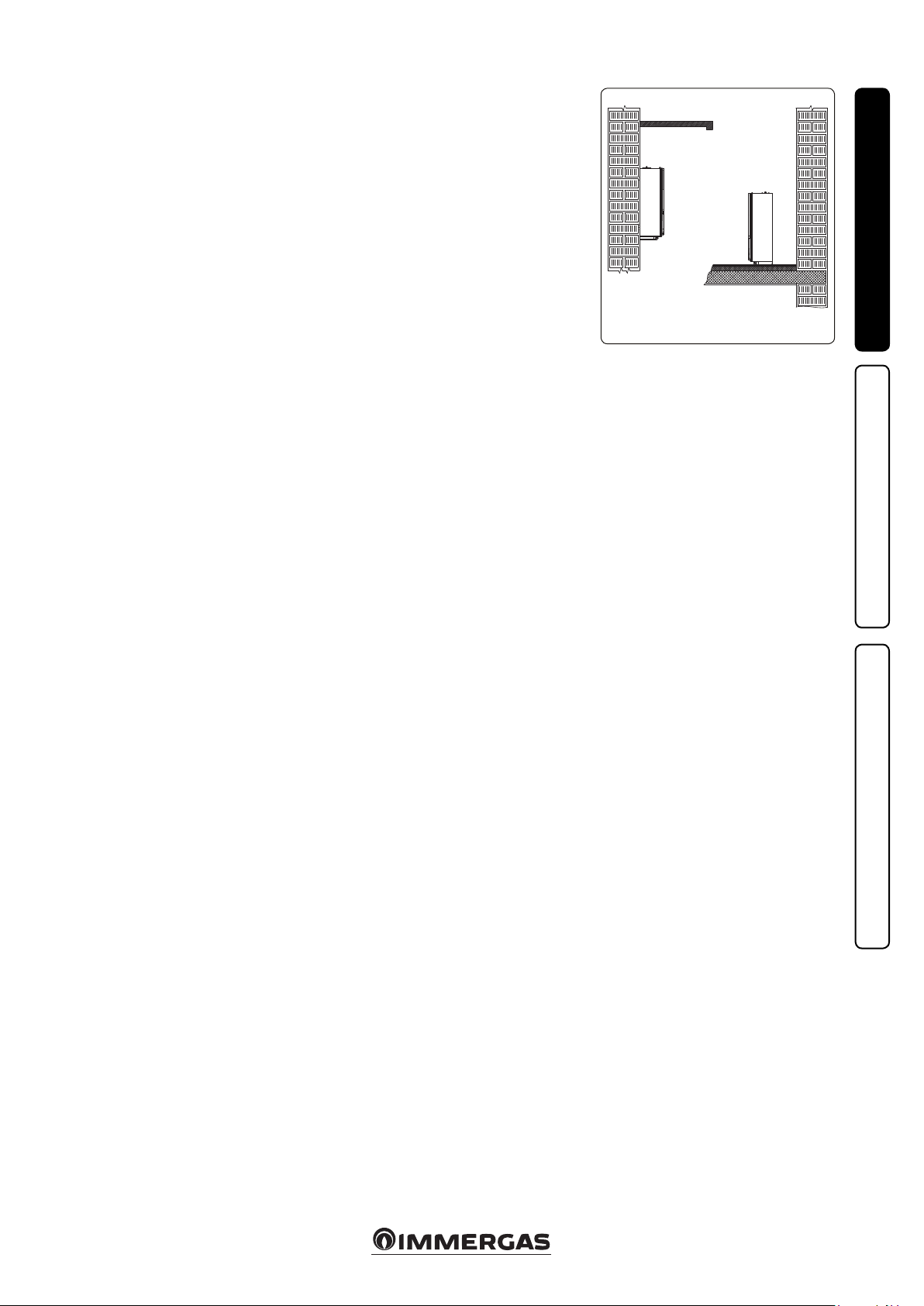
e wall surface must be smooth, without any
protrusions or recesses enabling access to the
rear part. ey are not designed to be installed
on plinths or oors (Fig. 1-1).
Only professionally enabled companies are authorised to install Immergas appliances.
Installation must be carried out according to the
provisions of the laws in force and in compliance
with local technical regulations and the required
technical procedures.
Before installing the appliance, ensure that it is
delivered in perfect condition; if in doubt, contact
the supplier immediately. Packing materials (staples, nails, plastic bags, polystyrene foam, etc.)
constitute a hazard and must be kept out of the
reach of children.
Should the appliance be contained inside or between pieces of furniture, there must be enough
space for routine maintenance; therefore, it is
recommendable to leave at least 3 cm between the
unit casing and the vertical walls of the furniture.
At least 25 cm of free space must be le above, in
order to be able to carry out maintenance and,
if necessary, install an additional resistance (optional). Leave space under the hydronic module
to allow the hydraulic connections to be serviced.
Keep all ammable objects away from the appliance (paper, rags, plastic, polystyrene, etc.).
Do not put household appliances under the hydronic module as they could be damaged if the
safety valve trips or if the hydraulic ttings leak.
Otherwise, the manufacturer cannot be held liable for any damage to the household appliances.
For the same reasons, it is also recommendable
not to put furnishings, furniture, etc. under the
hydronic module.
In the event of malfunctions, faults or incorrect
operation, turn the appliance o immediately
and contact an authorised company (e.g. the
Immergas Technical Assistance centre, which
has specically trained sta and original spare
parts). Do not attempt to modify or repair the
appliance alone.
Failure to comply with the above implies personal
responsibility and invalidates the warranty.
• Installation regulations:
- this hydronic module can be installed outdoors in a partially protected area. By partially protected area, we mean one in which the
unit is not directly exposed to the elements
(rain, snow, hail, etc.).
- Installation is prohibited on the vertical
projection of cooking hobs.
- Installation is also prohibited in places/environments that constitute common parts of
oce condominiums such as stairs, cellars,
entrance halls, attics, los, escape routes,
etc. if they are not located inside technical
compartments under the responsibility of
each individual building and only accessible
to the user (for the features of the technical
compartments, see the technical standards in
force).
- Using specic kits, the hydronic module can
be paired with other Immergas products
and installed inside an outdoor wall using
the specic Solar Container recessed frame
or mounted on an indoor wall in the Domus
Container.
Attention: Installing the wall recessed frame
kit must guarantee the hydronic module stable, ecient support. e recessed frame kit
ensures appropriate support only if installed
correctly (according to the rules of good
practice), following the instructions on its
instructions leaet. e recessed frame for
the hydronic module is not a load-bearing
structure and cannot replace the removed
wall. erefore, correct positioning inside
the wall must be checked. For safety reasons
to prevent leaks, the compartment that will
house the hydronic module in the masonry
wall must be plastered.
Attention: installing the hydronic module
mounted on the wall must ensure the generator
itself stable, ecient support.
e dowels (standard supplied with the unit) must
only be used to secure the unit to the wall; they can
only ensure sucient support if inserted properly
(according to the rules of good practice) on walls
built with solid or semi-hollow bricks. In the
case of walls made from hollow brick or block,
partitions with limited static properties, or in any
case walls other than those indicated, a static test
must be carried out to ensure adequate support.
ese hydronic units are used to heat water to below boiling temperature at atmospheric pressure.
ey must be connected to a central heating
system and domestic hot water circuit suited to
their performance and capacity.
Attention:e storage tank unit must also be
installed in an environment in which the temperature cannot fall below 0°C.
"Anti-Legionella" treatment of the Immergas
storage tank (function enabled when there is
an additional electrical resistance for domestic
hot water). During this phase, the temperature
of the water inside the tank exceeds 60°C with
the subsequent risk of burns. Keep this domestic water treatment under control (and inform
the users) to prevent unforeseeable damage
to people, animals, things. If required install a
thermostatic valve on the domestic hot water
outlet to prevent scalding.
INSTALLERUSERMAINTENANCE TECHNICIAN
YES NO
1-1
5
Page 6
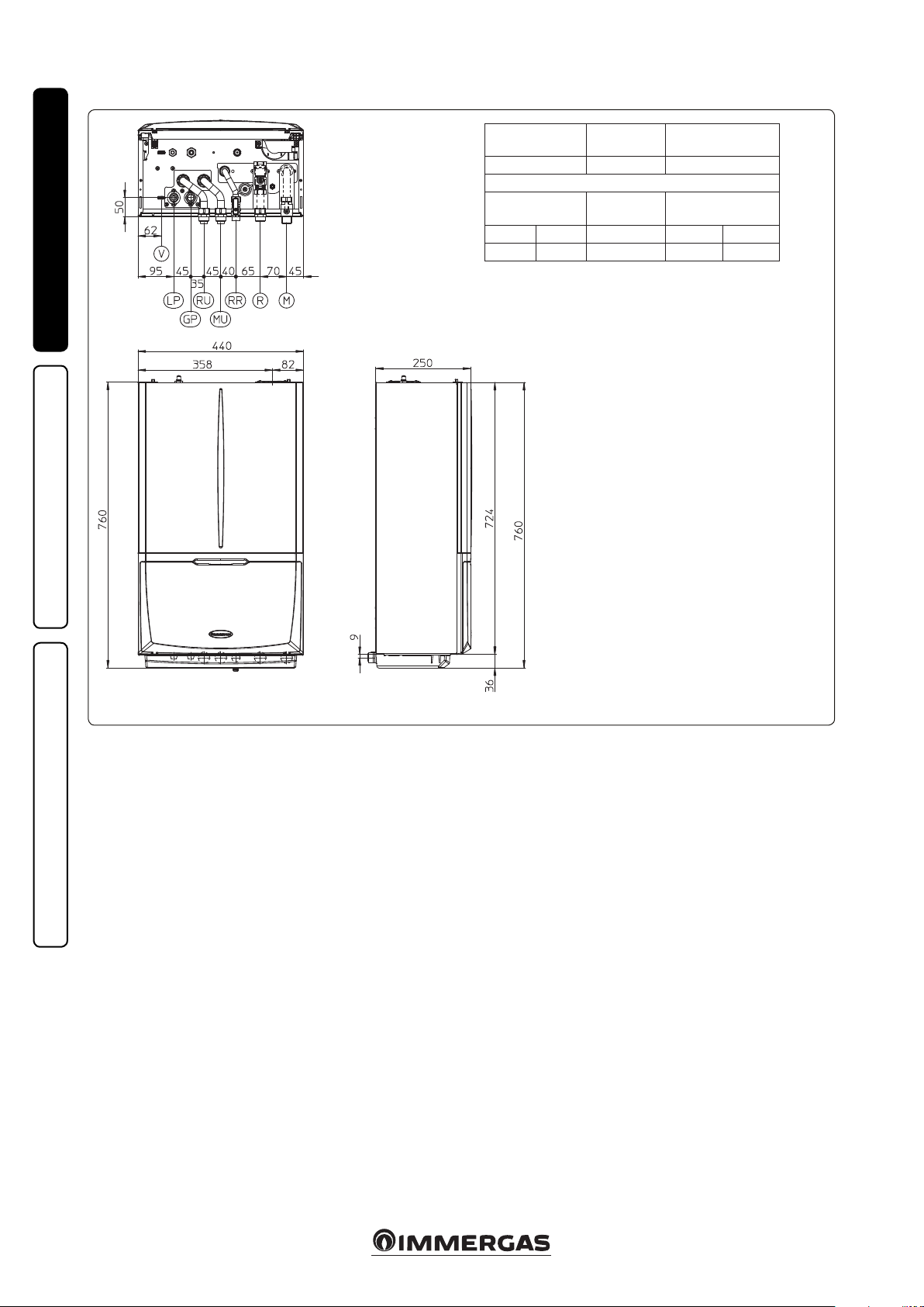
1.2 MAIN DIMENSIONS.
INSTALLERUSERMAINTENANCE TECHNICIAN
Height
(mm)
760 440 250
CHILLER LINE
LG GP RR R - M RU - MU
G 3/8” G 5/8” 1/2” 3/4” 3/4”
Width
(mm)
CONNECTIONS
DOMESTIC
HOT WATER
Key:
V - Electrical connection
RR - System lling
RU - Storage tank unit return
MU - Storage tank unit ow
R - System return
M - System ow
LP - Chiller line - liquid phase
GP - Chiller line - gaseous phase
Depth
(mm)
SYSTEM
1-2
1.3 ANTIFREEZE PROTECTION.
Minimum temperature -5°C. e hydronic unit
comes standard with an anti-freeze function that
activates the condensing unit when the temperature of the water inside of it falls below 4°C.
In these conditions, the hydronic unit is protected
against freezing up to an ambient temperature
of -5℃.
Minimum temperature -15°C. In the event the
hydronic unit is installed in a place where the
temperature falls below -5°C, it is possible for
the appliance to freeze.
To prevent the risk of freezing follow the instructions below:
- protect the central heating circuit from freezing
by inserting a good-quality antifreeze liquid
into this circuit, which is specially suited for
central heating systems and which is manufacturer guaranteed not to cause damage to
the heat exchanger or other components of
the hydronic module. e antifreeze liquid
must not be harmful to one's health. e instructions of the manufacturer of this liquid
must be followed scrupulously regarding
the percentage necessary with respect to the
minimum temperature at which the system
must be kept. An aqueous solution must be
made with potential pollution class of water 2
(EN 1717:2002).
e materials used for the hydraulic circuits of
Immergas hydronic units resist ethylene and
propylene glycol based antifreeze liquids (if the
mixtures are prepared perfectly).
For life and possible disposal, follow the sup-
plier's instructions.
- Protect the domestic hot water circuit against
freezing by using an accessory that is supplied
on request (antifreeze kit) comprising two
electric heating elements, the relevant cables
and a control thermostat (carefully read the
installation instructions contained in the accessory kit pack).
In these conditions, the hydronic unit is protected
against freezing up to a temperature of -15°C.
Hydronic unit anti-freeze protection (both -5°C
and -15°C) is only ensured if:
- e hydronic unit and the condensing unit are
properly connected to each other and to the
electrical supply voltage circuits;
- e units are continuously powered;
- e units are not in "o" mode.
- e units are not in anomaly (parag. 2.5);
- e unit and/or kit essential components are not
faulty.
e warranty does not cover damage due to interruption of the electrical power supply and failure
to comply with that stated on the previous page.
N.B.: if the hydronic unit is installed in places
where the temperature drops below 0°C, the
domestic hot water connection pipes must be
insulated.
6
Page 7
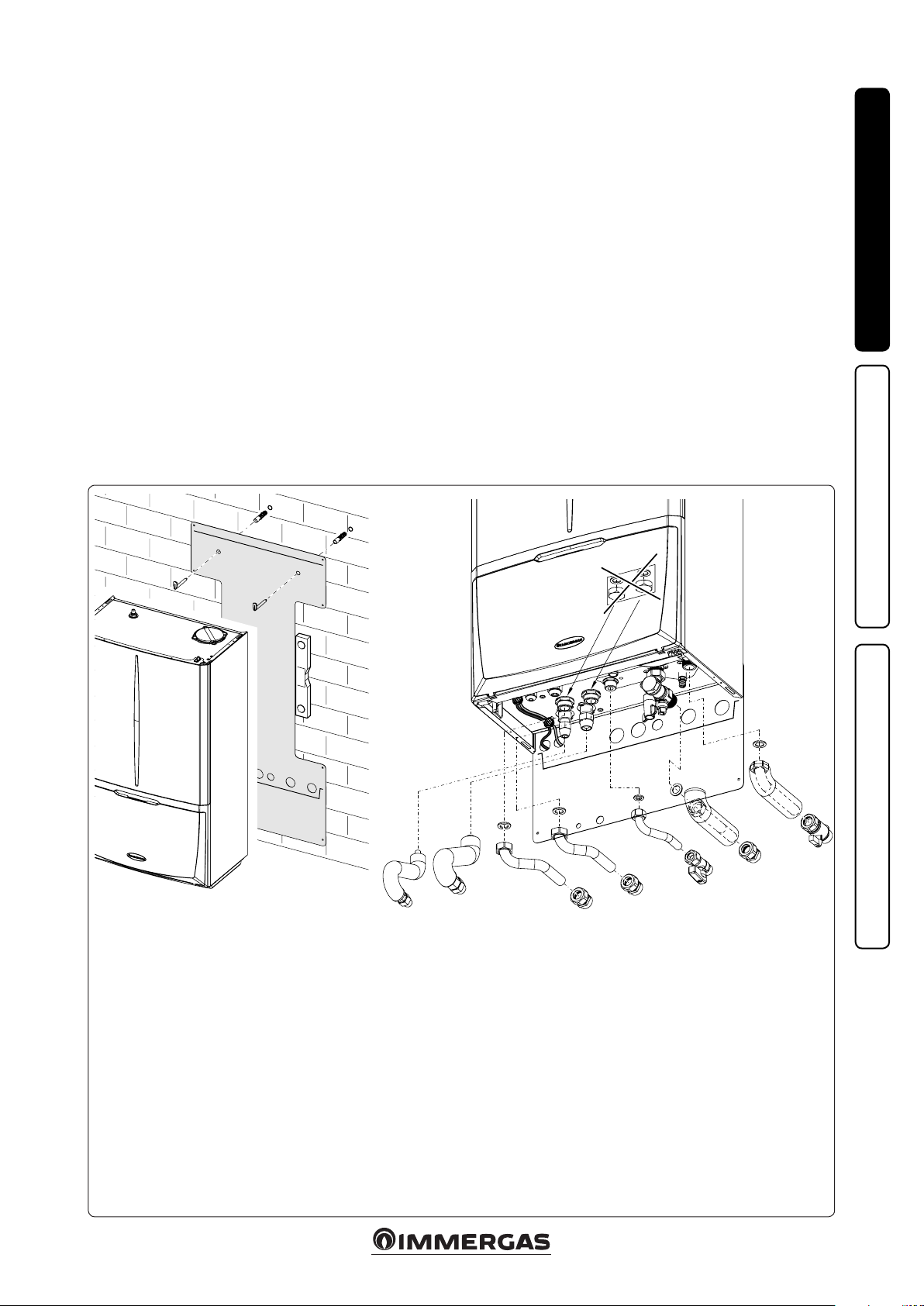
1.4 HYDRONIC MODULE
CONNECTION UNIT.
- e hydraulic connection unit is standard sup-
plied with Magis Pro ErP. Make the hydraulic
connection as shown below, making sure to
protect the system ow and return pipes with
their supplied insulating sheaths.
- The R410A circuit wall connection unit is
supplied as an extra kit. Connect the circuit,
following the instructions provided in the
condensing unit instructions booklet.
1.5 HYDRAULIC CONNECTION.
Attention: in order not to void the product war-
ranty, before making unit connections, carefully
clean the heating system (pipes, radiators, etc.)
with special pickling or de-scaling products to
remove any deposits that could jeopardise proper
hydronic module operation.
A chemical treatment of the heating system water
is required, in compliance with the technical
standards in force, in order to protect the system
and the appliance from deposits (e.g. scale),
slurry or other hazardous deposits.
Hydraulic connections must be made rationally,
using the couplings on the hydronic module
template.
Attention: Immergas declines all liability in the
event of damage caused by the inclusion of automatic lling that is not its own brand.
In order to meet the system requirements established by EN 1717 regarding the pollution
of drinking water, we recommend installing the
IMMERGAS anti-backow kit upstream of the
hydronic unit cold water inlet connection. We
also recommend using a category 1, 2 or 3 heat
transfer uid (ex: water + glycol) in the hydronic
unit primary circuit (CH circuit), as dened in
the EN 1717 standard.
Attention: to preserve appliance duration and
eciency features, we recommend installing a
suitable water treatment device if the water has
features that can lead to limescale deposits.
1.6 CONNECTING THE CHILLER LINE.
As far as connecting the chiller line is concerned,
all the instructions contained in the Audax Pro
condensing unit instructions booklet must be
followed.
Make the connections directly on the hydronic
module couplings, or use the rear outlet kit
(optional).
INSTALLERUSERMAINTENANCE TECHNICIAN
e hydraulic connection kit includes:
2 - adjustable expansion bolts
2 - hydronic module support hooks
1 - 3/4” storage tank unit return pipe (RU)
1 - 3/4” storage tank unit ow pipe (MU)
1 - 1/2” system lling pipe (RR)
1 - 1/2” ball valve (RR)
1 - 3/4” system return pipe (R)
1 - 3/4” system ow pipe (M)
1 - 3/4” ball valve (M)
2 - Insulating sheath for system pipes (R - M)
4 - 3/4” telescopic ttings (RU - MU - R)
Gaskets, screws and seal O-Ring
e R410A circuit wall connection kit (optional) includes:
1 - G 3/8” liquid phase chiller line pipe (LP)
1 - G 5/8” gaseous phase chiller line pipe (GP)
MU
RU
V
V
GP
LP
LP
GP
RU
MU
M
R
RR
M
R
RR
Key:
V - Electrical connection
RR - System lling
RU - Storage tank unit return
MU - Storage tank unit ow
R - System return
M - System ow
LP-Chiller line - liquid phase
GP-Chiller line - gaseous phase
Already installed on the module:
1 - System interception tap with 3/4” lter (R)
1-3
7
Page 8
1.7 ELECTRIC CONNECTION.
e appliance has an IPX4D degree of protection;
electrical safety of the appliance is achieved only
when it is properly connected to an ecient
earthing system, as specied by current safety
standards.
Attention: Immergas S.p.A. declines any responsibility for damage or physical injury caused by
failure to connect the hydronic module to an
ecient earthing system or failure to comply
with the reference standards.
INSTALLERUSERMAINTENANCE TECHNICIAN
- Connection cables must respect the prear-
ranged routes. Use 3 clips (c) (not supplied)
to group the individual cables (max. 1.5 mm2
into the lower terminal board. Use the specic
fairleads (d) on the le side, making sure to put
at most 2 multi-polar cables (max 3 x 1 mm2)
in each fairlead.
As an example, gure 1-5 shows cables in a
hypothetical connection. To make the connections based on your own requirements, see the
instructions below.
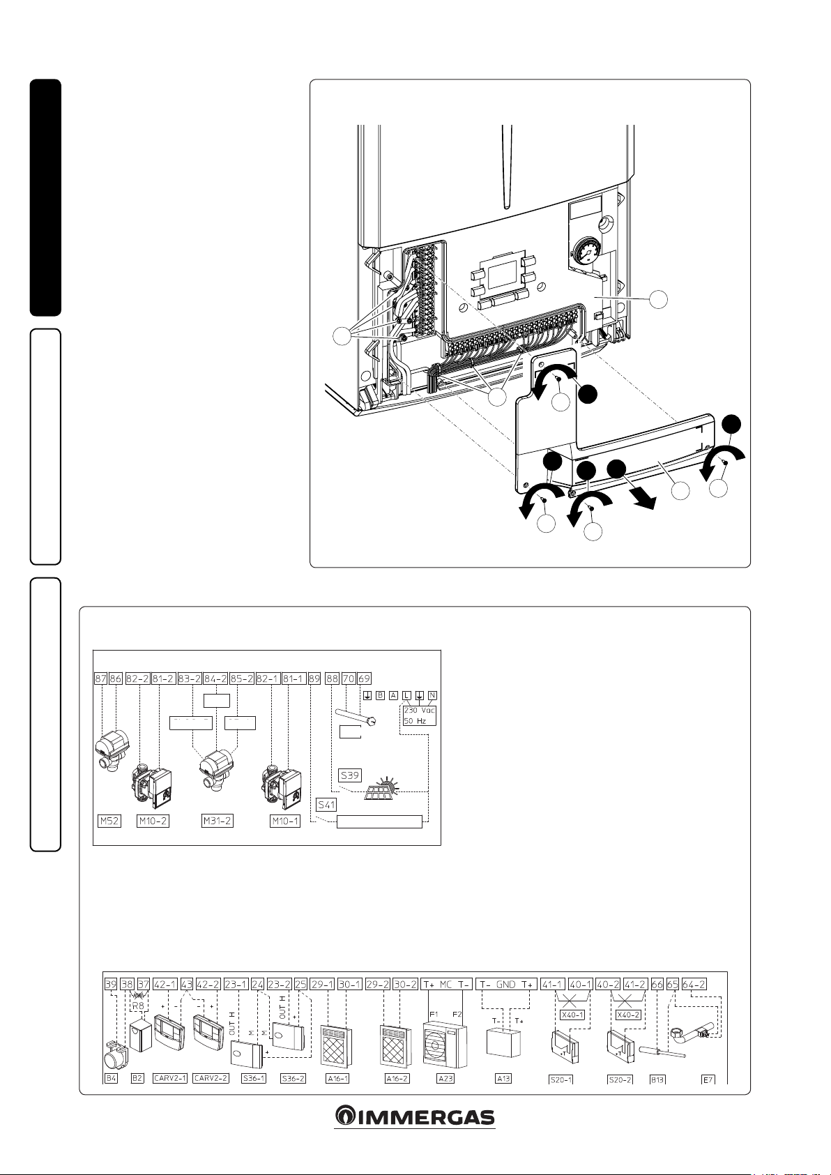
• Open the control panel connections compart-
ment (Fig. 1-5).
To carry out electrical connections, all you have
to do is open the connections compartment as
follows.
- Remove the front panel (Fig. 3-5b).
- Remove the cover (b g. 1-4).
1) Loosen the screws (a).
2) Remove the cover (b) from the control
panel (c).
- At this point, you can access the terminal board.
Also ensure that the electrical installation corresponds to the maximum absorbed power speci-
1-4
c
d
c
1
a
1
1
a
2
1
a
b
a
1-5
COM.
CLOSED OPEN
DHW
DIS. AUDAX PRO
Key:
86 /87 - Summer winter switch 3-way valve
81-2 / 82-2 - Zone 2 circulator
83-2 / 84-2 / 85-2 - Zone 2 mixing valve
82-1 / 81-1 - Zone 1 circulator
89 / L - Audax Pro disabling contact
88 / L - Solar inlet
69 / 70 - Domestic hot water integrated resistance control
38 / 39 - External Probe
37 / 38 - Domestic hot water probe (eliminate R8)
42-1 / 43 - Zone 1 CAR
42-2 / 43 - Zone 2 CARV2
23-1 / 24 - Zone 1 humidistat or humidity probe
23-2 / 24 - Zone 2 humidistat or humidity probe
25 - Humidity sensor supply voltage
29-1 / 30-1 - Zone 1 dehumidier
29-2 / 30-2 - Zone 2 dehumidier
T+ / T- (MC) - Audax Pro communication bus
T+ / T- (RS485) - Other Immergas appliance communication
bus
41-1 / 40-1 - Zone 1 room thermostat
41-2 / 40-2 - Zone 2 room thermostat
66 / 65 - Puer central heating probe
65 / 64-2 - Zone 2 ow probe
V2
8
Page 9
45
cations shown on the hydronic unit data plate.
e hydronic units are supplied complete with
a special “X”-type power cable without a plug.
e power supply cable must be connected to a
230V ±10% / 50Hz mains supply respecting L-N
polarity and earth connection; this network
must also have a multi-pole circuit breaker with
class III over-voltage category.
To protect from possible dispersions of DC voltage, it is necessary to provide a type A dierential
safety device.
When replacing the power supply cable, contact a
qualied company (e.g. the Immergas Authorised
Aer-Sales Technical Assistance Service). e
power cable must be laid as shown (Fig. 1-3).
If the fuses on the electronic boards must be
replaced, use:
- P.C.B.: a T 3.5 A fuse
- heat pump communication board: a T 5.0 A
fuse
For the main power supply to the appliance,
never use adapters, multiple sockets or extension leads.
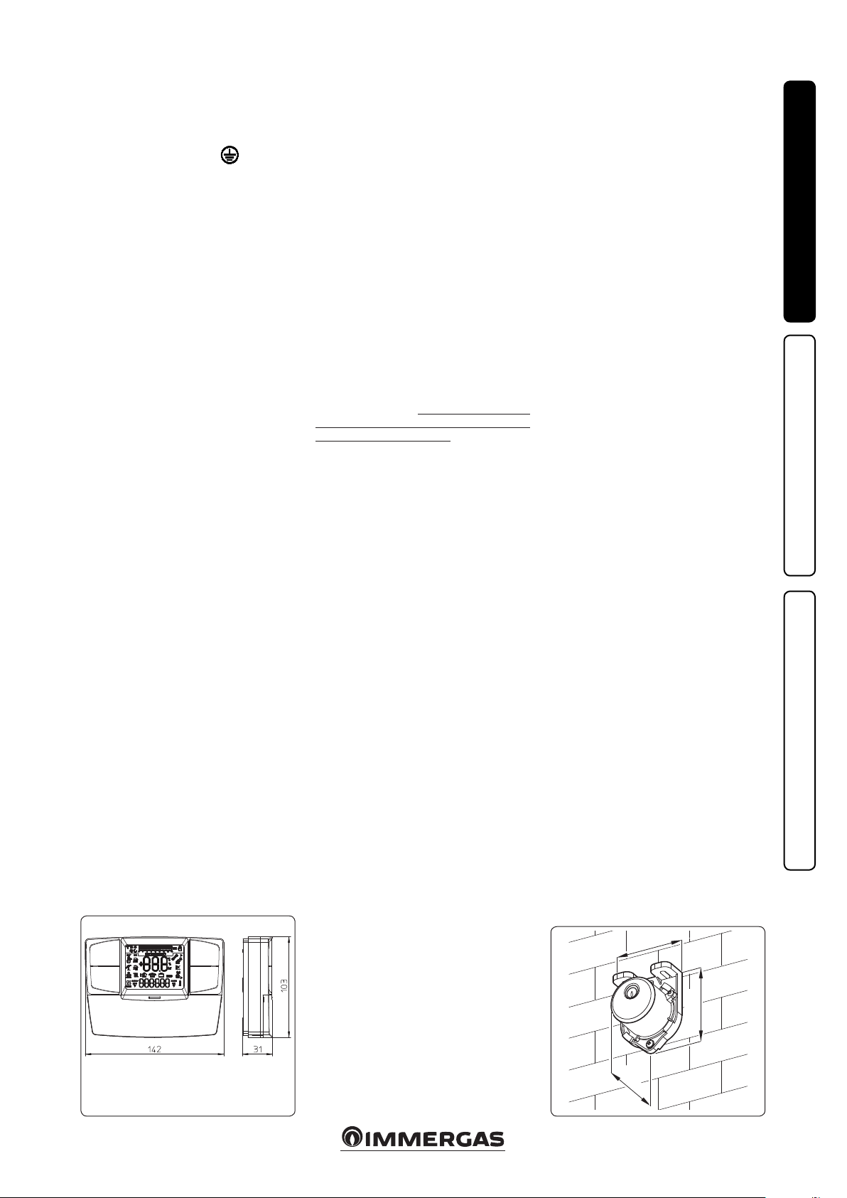
1.8 REMOTE CONTROLS AND
ROOM CHRONOTHERMOSTATS
OPTIONAL.
The hydronic module is set up for room
chrono-thermostats or remote controls, available as optional kits (Fig. 1-6). A maximum of
2 thermo-regulators can be applied directly to
the appliance.
All Immergas chrono-thermostats are connected
with 2 wires only. Carefully read the user and
assembly instructions contained in the accessory kit.
• On/O Immergas digital chrono-thermostat.
e chrono-thermostat allows:
- set two room temperature value: one for
daytime (comfort temperature) and one for
night-time (reduced temperature);
- set a weekly program with four daily switch
on and switch o times;
- select the required operating mode from the
various possible alternatives:
• manual operation (with adjustable tempera-
ture).
• automatic operation (with set programme).
• forced automatic operation (momentarily
changing the temperature of the automatic
programme).
e chrono-thermostat is powered by two 1.5V
LR 6 type alkaline batteries.
• Comando Amico Remoto Remote Control
Device V2 (CARV2) with climate chrono-thermostat function. In addition to the functions
described in the previous point, the CARV2
panel enables the user to control all the important information regarding operation of
the appliance and the heating system with the
opportunity to easily intervene on the previously set parameters, without having to go
to where the appliance is installed. e panel
is equipped with self-diagnosis to show any
appliance operating anomalies on the display.
e climate chrono-thermostat incorporated
into the remote panel enables the system ow
temperature to be adjusted to the actual needs
of the room being heated or cooled, in order
to obtain the desired room temperature with
extreme precision and therefore with evident
savings in running costs. e CARV2 is powered
directly by the hydronic module by the same
2 wires used to transmit data between the
hydronic module and the device.
Important: the hydronic module is set up to be
able to work with two CARV2 used to control two
separate hydraulic zones.
Comando Amico Remoto Remote Control V2
or On/O chrono-thermostat electrical connections (Optional). e operations described
below must be performed aer having removed
the voltage from the appliance.
-On/O ambient thermostat or chrono-thermostat: must be connected to the 40-1 / 41-1
terminals, eliminating the X40-1 jumper for
zone 1 and 40-1 / 41-1 for zone 2. Make sure
that the On/O thermostat contact is of the
“clean” type, i.e. independent of the mains voltage, otherwise the P.C.B. would be damaged.
- V2 Comando Amico Remoto remote control
must be connected to terminals 42-1 / 43 for
zone 1 and 42-2 / 43 for zone 2, keeping the
X40-1 jumper for the CARV2 in zone 1 and adding another one for zone 2 on terminals 40-2
and 41-2, being careful not to invert polarity
in the connections.
e connections must be made on the terminal
board inside the appliance control panel as described in gure 1-5.
Important: if the Comando Amico Remoto Remote Control V2 or any other On/Off
chrono-thermostat is used, arrange two separate
lines in compliance with current regulations regarding electrical systems. e hydronic module
pipes must never be used to earth the electrical
or telephone system. Make sure this does not
happen before making the hydronic module
electrical connections.
1.9 EXTERNAL TEMPERATURE PROBE.
In general, Magis Pro ErP uses the probe standard supplied on the condensing unit to read the
outdoor temperature.
If the condensing unit is positioned in an area
that is not suitable for temperature reading, it
is advisable to use an additional external probe
(Fig. 1-7), which is available as an optional kit.
Refer to the relative instruction sheet to position
the optional external probe.
e probe can be connected directly to the hydronic module electrical system and allows the
system ow temperature to be set automatically
based on the outdoor temperature in order to
adapt the heat or cooling provided to the system.
e external probe always operates when connected, regardless of the presence or type of room
chrono-thermostat used and can work in combination with Immergas chrono-thermostats.
e correlation between system ow temperature
and outdoor temperature is managed dierently
based on whether the system is managed directly
by the hydronic module or by the CARV2; the
parameters set on the chrono-thermostat take
priority over those set on the hydronic module.
- Hydronic module: the system ow temperature
is determined by the setting on the "Heat regulation" menu and by the "User" menu for the
oset values based on the curves shown in the
diagram (Fig. 1-8).
- CARV2: the system ow temperature is determined by the setting on the central heating
selector (which can be adjusted from 0 to 9)
and by the "Oset" value on the "Regulat." menu
based on the curves shown in the corresponding instructions booklet.
N.B.: if the system is divided into two zones,
the ow temperature is calculated based on the
zone with the higher temperature in central
heating mode and with the lower temperature
in cooling mode.
e electric connection of the external probe
must be made on terminals 38 and 39 on the
terminal board on the hydronic module control
panel (Fig. 1-5).
INSTALLERUSERMAINTENANCE TECHNICIAN
1-6
58
31
1-7
9
Page 10
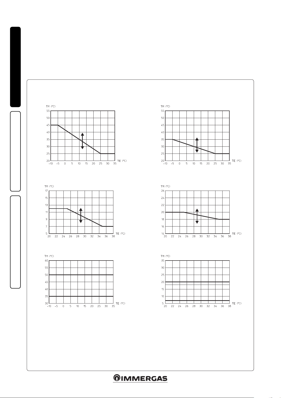
1.10 HEAT REGULATION SETTING.
By setting the parameters in the "Heat regulation"
menu, you can adjust how the system operates.
e curves (Fig. 1-8) show the default settings in
the various operating modes available both with
external probe and without.
INSTALLERUSERMAINTENANCE TECHNICIAN
Zone 1 ow temperature in central heating mode, with
R04
R05
R02 R03
Zone 1 ow temperature in cooling mode, with exter-
R13
R12
external probe
U03
nal probe
U05
Zone 2 mixed ow temperature in central heating
mode, with external probe
U04
R08
R09
R06 R07
Zone 2 mixed ow temperature in cooling mode, with
external probe
U06
R17
R16
R11 R10
Flow temperature in central heating mode without
Set Risc
U01
Key:
Rxx - "Heat regulation" menu parameter
TE - Outdoor temperature
TM - Flow temperature
U01 - Zone 2 ow temperature in "User" menu central
heating mode
1-8
external probe
Z1
Z2
R15 R14
Flow temperature in cooling mode without external
U02
Set Raresc
U02 - Zone 2 ow temperature in "User" menu cooling
mode
U03÷06 - Oset value compared to the curve set by the
external probe
Zx - Heating system zone
probe
Z2
Z1
10
Page 11
1.11 FILLING THE SYSTEM.
Once the hydronic module is connected, ll the
heating system using the lling cock (Fig. 1-33
and 1-4). Filling must be done slowly to allow
the air bubbles in the water to escape through
the vents in the hydronic module and the heating
and air conditioning system.
e hydronic module has one incorporated automatic
vent valve located on the circulator and another on
the central heating manifold. Make sure that the hoods
are loosened.
e lling cock must be closed when the hydronic module pressure gauge indicates approximately 1.2 bar.
N.B.: during these operations, enable the "Venting" functions by setting the "M01" parameter to
ON, which lasts about 18 hours (see the "P.C.B.
programming" paragraph).
System minimum water content.
Minimum water content is mainly important to
provide proper execution of defrosting cycles.
To this end, the minimum amount of water to
guarantee is 7 l/kW for any type of system.
N.B.: it is also important to check that the
dehumidier line has a minimum of 3 l/kW
(dehumidier hydraulic circuit connection).
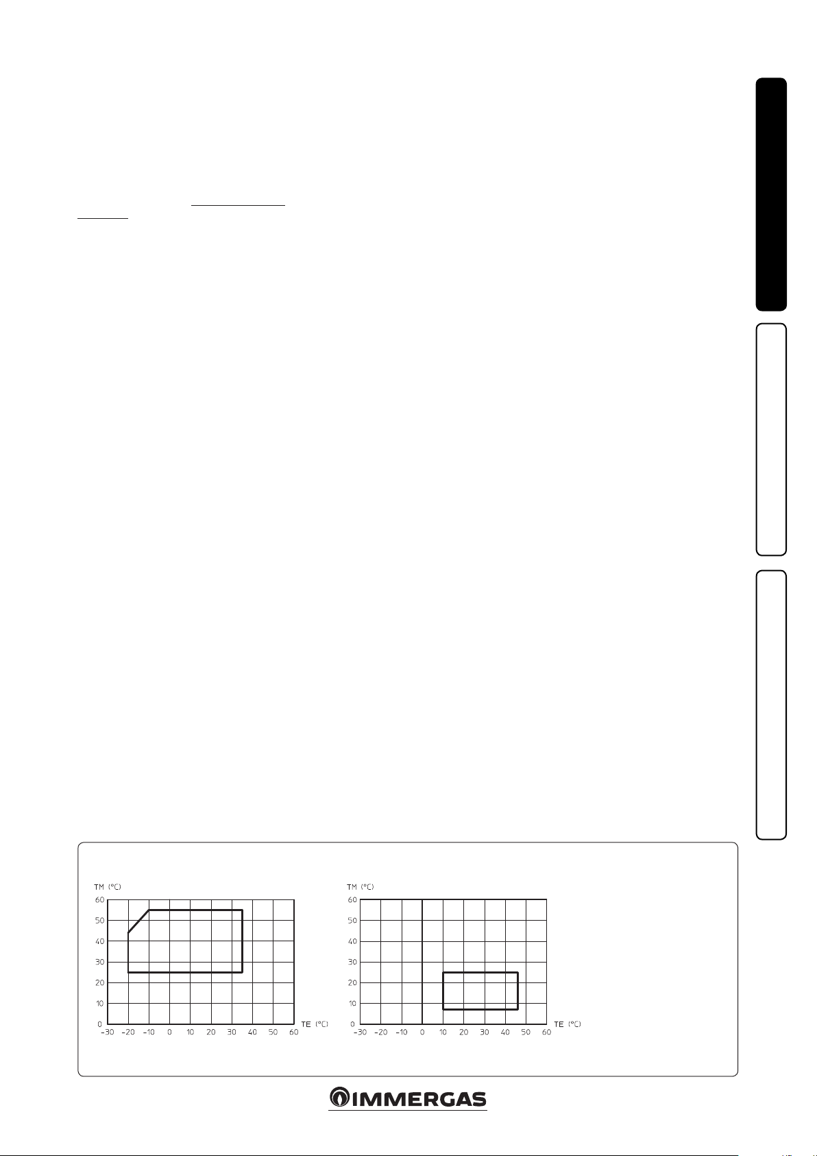
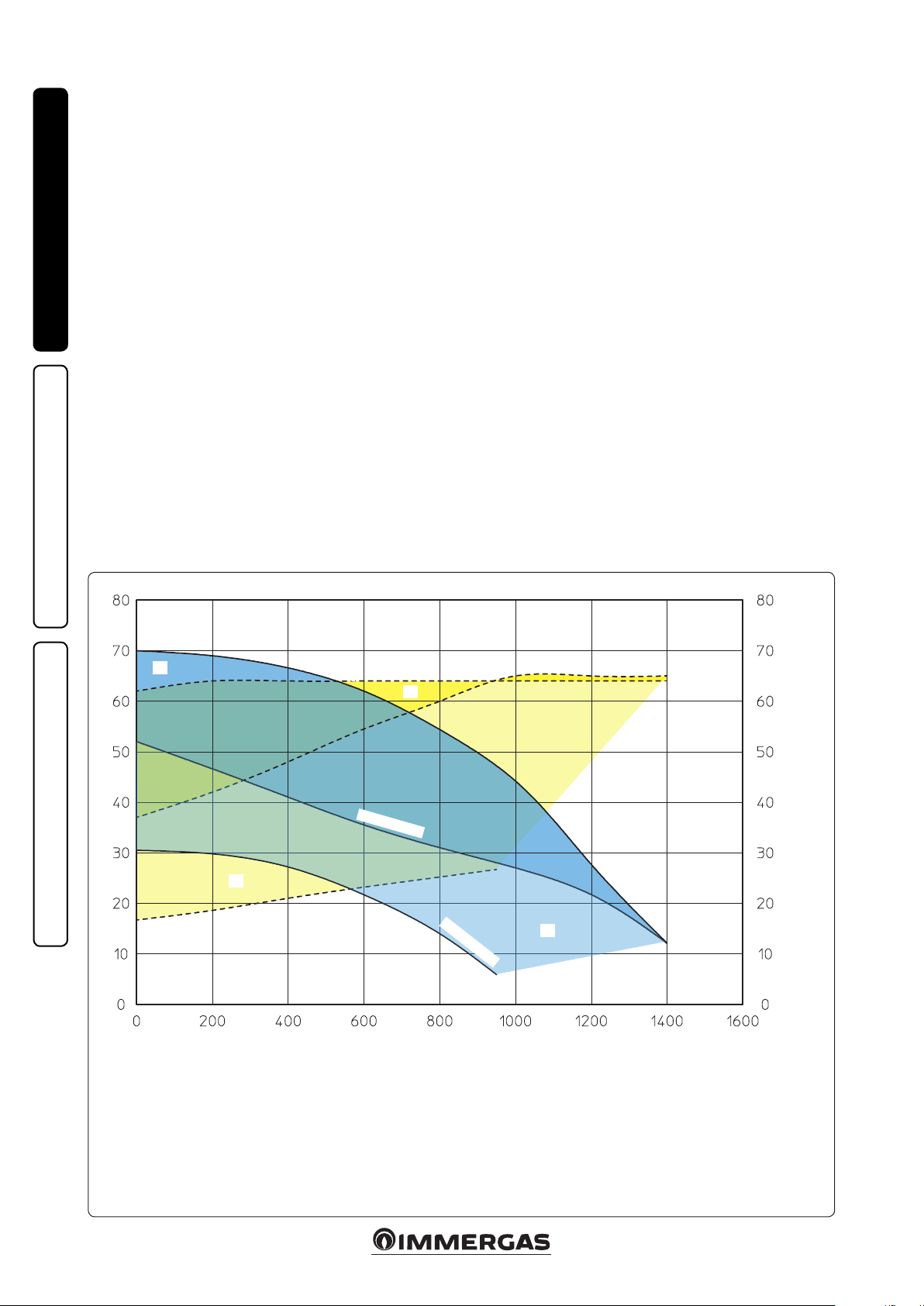
1.12 OPERATING LIMITS.
e system was designed to work in a specic
range of temperatures and at a specic maximum
ow temperature. e graphic (Fig. 1-9) shows
these limits.
1.13 COMMISSIONING THE HYDRONIC
MODULE IGNITION.
The following requirements must be met to
commission the hydronic module in order to
issue the Declaration of Conformity, if required
by the technical standards in force (the following
operations must be done only by professionally
qualied personnel and in the presence of professionals only):
- check that the internal system is properly sealed
according to the specications set forth by
technical regulations in force;
- check connection to a 230V-50Hz power
mains, correct L-N polarity and earthing
connection;
- switch on the hydronic module and check for
proper ignition;
- check the operation of the main switch located
upstream of the hydronic module and on the
module itself;
Should even just one of these checks have a
negative outcome, the system must not be
commissioned.
INSTALLERUSERMAINTENANCE TECHNICIAN
Operating limits in central heating mode Operating limits in cooling mode
1-9
11
Key:
TE = Outdoor temperature.
TM = Flow temperature
Page 12
1.14 CIRCULATION PUMP.
e hydronic modules are supplied with a variable speed circulator, which operates at the speed
set in the "A04" parameter (which can be set
between 55% and 100%). e minimum speed
set on the "A03" parameter is used for special
functions (e.g. pump anti-locking function).
Attention: for proper system operation, make
sure that the minimum ow in operating conditions never drops below 500 l/h.
Pump release. If, aer a prolonged period of
INSTALLERUSERMAINTENANCE TECHNICIAN
inactivity, the circulation pump is blocked, turn
the motor sha using a screwdriver. Take great
care during this operation to avoid damage to
the motor.
By-pass Regulation (part. 17 Fig. 1-11). e
hydronic module comes out of the factory with
the by-pass closed.
If necessary, the by-pass can be regulated to
system requirements from minimum (by-pass
closed) to maximum (by-pass open). Adjust
using a at head screwdriver, turn clockwise
and open the by-pass, anticlockwise it is closed.
Total head available to the system.
A
Head (kPa)
D
Max. speed
Max. speed
C
Circulator pump absorbed power (W)
Min. speed
B
1-10
Flow rate (l/h)
A+B = Head available with by-pass closed
B = Head available with by-pass open
C+D = Power absorbed by the pump with by-pass open (dotted area)
D = Power absorbed by the pump with by-pass closed (dotted area)
12
Page 13
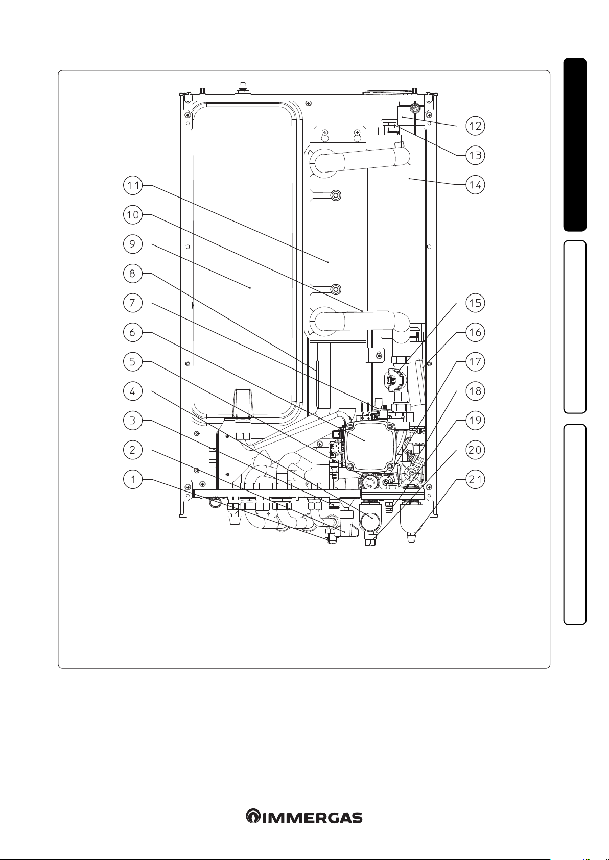
1.15 HYDRONIC MODULE COMPONENTS.
1-11
INSTALLERUSERMAINTENANCE TECHNICIAN
Key:
1 - Domestic hot water inlet valve
2 - System lling valve
3 - 3-bar safety valve drain tting
4 - Inspectable lter
5 - 3 bar safety valve
6 - Hydronic unit circulator
7 - Vent valve
8 - Liquid phase detection probe
1.16 KITS AVAILABLE ON REQUEST.
• 3 kW heating system integrated resistance
kit. Should it be necessary, you can install an
electrical resistance to supplement the central
heating system; this resistance can be installed
directly inside the hydronic module.
• 2 zone kit (1 direct and 1 mixed). Should it be
necessary, you can install the zone kit, which
allows you to divide the heating system into
two separate zones - one direct and one mixed.
• Congurable relay interface kit. e module
is set up for a relay board, which amplies the
9 - System expansion vessel
10 - Flow probe
11 - Plate heat exchanger
12 - Vent valve
13 - Central heating integrated electrical
resistance cap (optional)
14 - Central heating manifold
15 - System ow meter
16 - Return probe
17 - By-pass
appliance features and, thus, the operating
possibilities.
• 2 relay board kit. e hydronic module can
manage up to two dehumidiers. A 2 relay
board that manages dehumidier enabling is
available to pair the appliances.
• R410A circuit connection kit. For R410A
circuit wall connections, there is a kit with the
two pipes necessary to create the circuit.
13
18 - ree-way valve (motorised)
19 - System draining valve
20 - System cut-o tap
21 - System cut-o tap
e above-mentioned kits are supplied complete
with instructions for assembly and use.
Page 14

USE AND MAINTENANCE
2
INSTRUCTIONS
2.1 CLEANING AND MAINTENANCE.
Attention: to preserve system integrity and keep
the distinguishing safety features, performance
and reliability unchanged over time, you must
execute maintenance operations at least on a
yearly basis in compliance with what is stated in
the point regarding “annual appliance check and
maintenance”. Annual maintenance is essential to
validate the conventional warranty of Immergas.
INSTALLERUSERMAINTENANCE TECHNICIAN
We recommend stipulating a yearly cleaning and
maintenance contract with your zone Immergas
Authorised Aer-sales Service.
2.2 GENERAL WARNINGS.
Do not expose the hydronic module to direct
steam from cooking surfaces.
Children and unskilled persons are not allowed
to use the hydronic module.
Should you decide to temporarily shut down the
hydronic module, you must:
a) drain the heating system if antifreeze is not
used;
b) shut o the electrical and water supply.
Never clean the appliance or connected parts
with easily ammable substances.
Never leave containers or ammable substances
in the same environment as the appliance.
• Attention: using any components that use
electrical power requires some fundamental
rules to be observed:
- do not touch the appliance with wet or moist
parts of the body; do not touch when barefoot;
- never pull electrical cables or leave the appliance exposed to weathering (rain, sunlight,
etc.);
- the appliance power cable must not be replaced by the user;
- in the event of damage to the cable, switch
off the appliance and contact exclusively
qualied sta for replacement;
- if the appliance is not to be used for a certain
period, disconnect the main power switch.
N.B.: the temperatures shown on the display
have a tolerance of +/- 3°C due to environmental conditions that cannot be attributed to the
hydronic module.
At the end of its service life, the appliance must
not be disposed of like normal household waste
nor abandoned in the environment, but must
be removed by a professionally authorised
company. Contact the manufacturer for disposal
instructions.
2.3 CONTROL PANEL.
2-1
ESC OK
Key:
1 - Operating mode (winter - heating/air
conditioning - summer - stand-by - o)
and parameter conrm button
2 - Menu selection button
3 - Reset and exit menu button
4 - Domestic hot water temperature selec-
tion buttons
5 - Heating system temperature selection
buttons
6 - Hydronic module pressure gauge
7 - Remote control connection (optional)
8 - Condensing unit operation in progress
bar
9 - Not used
10 - Dispensed output level
11 - Operation with external temperature
probe active (optional)
12 - Connection to other Immergas units
13 - Room central heating mode active
14 - Temperature indicator, hydronic module
info and error codes
15 - Room cooling mode operation active
16 - Operation in cooling mode
17 - Operation in winter mode
18 - Operation in summer mode
19 - Stand-by mode
20 - Not used
21 - Hydronic module locked, requiring
release by "RESET" button
22 - Operation in dehumidication mode
23 - DHW production phase operating mode
active
14
Page 15
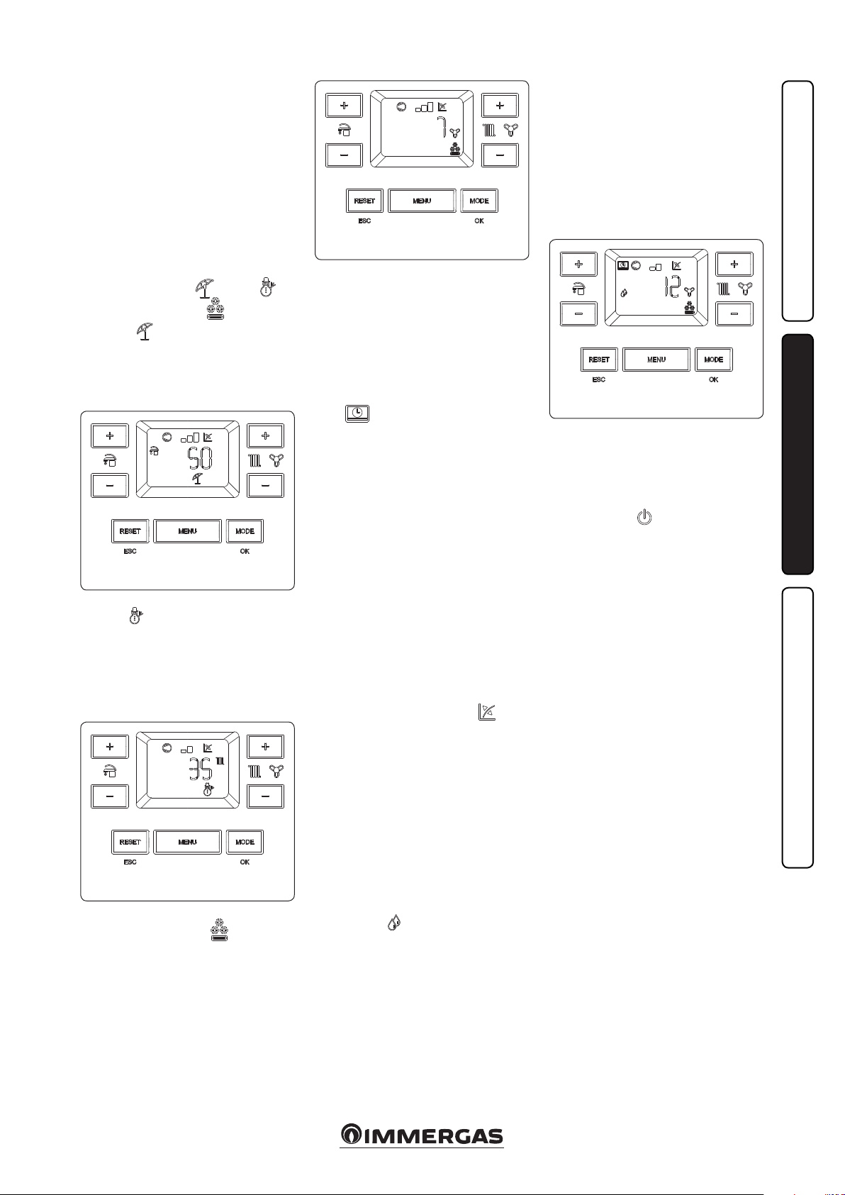
2.4 SYSTEM USE.
Before ignition, make sure the system is full of
water, checking that the pressure gauge needle
(6) points to a value between 1 and 1.2 bar and
make sure that the chiller circuit has been lled
as described in the condensing unit instructions
booklet.
- Press the button (1) until the display switches
on. e system now goes back to the state prior
to switch-o.
- If the hydronic module is in stand-by, press the
button (1) again to activate it. Otherwise, go to
the next point.
- en press the button (1) in sequence and set
the system to summer ( ), winter ( ) or
heating/air conditioning ( ) position.
• Summer ( ): in this mode, the system only
works to produce domestic hot water, the
temperature is set using the buttons (4) and
the corresponding temperature is shown on
the display by the indicator (14).
Summer and DHW heating in
progress mode
• Winter ( ): in this mode, the system works
both to product domestic how water and room
central heating. e temperature of the DHW
is always regulated via buttons (4), the central
heating temperature is regulated via buttons
(5) and the relative temperature is shown on
the display by the indicator (14).
Winter and room central heating in
progress mode
• Heating/air conditioning ( ): in this mode,
the system works both to produce DHW and to
cool the room. e temperature of the DHW
is always regulated via buttons (4), the cooling
temperature is regulated via buttons (6) and the
relative temperature is shown on the display by
the indicator (14).
2-2
2-3
Heating/Air conditioning and room
cooling in progress mode
From here on, the system works automatically.
If there are no requests (room central heating,
DHW production or cooling), the system goes
into the "stand-by" function. Each time the
condensing unit ignites, the display shows the
corresponding symbol (8) with the corresponding power scale (10).
• Operation with Comando Amico RemotoV2
(CARV2) (Optional). If the CARV2 is connected,
the ( ) symbol will appear on the display.
e system regulation parameters can be set via
the CARV2 control panel and the reset button
(3) remains active on the hydronic module
control panel, along with the switch-o button
(1) (“o ” mode only) and the display showing
the functioning state.
e system is set up to manage two CARV2.
e CARV2 connected to the main zone (zone
2 or low temperature) is considered as the
hydronic module mount panel, while the
CARV2 connected to the secondary zone (zone
1 or high temperature) manages the requests
in the corresponding zone. Consequently, the
"secondary" CARV2 is not to be considered as
the hydronic module mount panel.
Attention: if the hydronic module is switched
“o” the CARV2 will display the connection
error symbol “ERR>CM”. e CARV2 is still
powered constantly so as not to lose the saved
programs.
•Operation with external probe ( ). e
system is set up to use the condensing unit
external probe or an optional external probe.
With the external probe connected, the system
ow temperature for room heating and air
conditioning is managed by the external probe
based on the outdoor temperature measured
(Parag. 1.9). You can change the ow temperature by choosing the oset value in the specic
user menu. If the CARV2 is connected, you can
change the operating curve using the controls
on it, selecting a value from "0 to 9" (See CARV2
instructions). In this case, any settings made
on the hydronic module will not aect system
operation.
• Dehumidify ( ). If the system is paired with
a humidistat (optional) or a humidity temperature sensor (optional), you can manage the
2-4
room humidity in summer air conditioning
mode.
- If paired with a humidistat, set the degree
of humidity on the humidistat itself (see the
instructions booklet).
- If paired with a humidity temperature sensor,
set the humidity percentage in the corresponding user menu or, if there is a CARV2,
you can set it on the remote control itself from
the "S UR %" parameter.
Heating/Air conditioning and
Dehumidication active mode
• In central heating or cooling request mode,
if the temperature of the water in the system
meets the request, the system can work simply
by activating the circulator.
• “Stand-by” mode. Press button (1) repeatedly
until the symbol ( ) appears. From then on,
the system remains inactive and the antifreeze
function, pump anti-block function and 3-way
and signalling of any anomalies is guaranteed.
N.B.: in these conditions the system must still
be considered powered.
• “O” mode. By holding the button (1) down
for 8 seconds, the display switches o and the
hydronic module is completely o. e safety
functions are not guaranteed in this mode.
N.B.: in these conditions, the hydronic module
must still be considered powered even if there
are no functions active.
• “Automatic vent” mode. Every time the
hydronic module is electrically powered, the
system automatic vent function is activated
(lasting 8 minutes). is function is displayed
via a countdown signalled by the indicator (14).
During this period the DHW and CH functions
are not active.
e “automatic vent” can be annulled by press-
ing the “reset” button (3).
• Display operation. e display lights up while
the control panel is being used; aer a set inactivity period, the brightness drops until only
the active symbols are displayed. e lighting
mode can be varied via parameter t8 in the
P.C.B. programming menu.
2-5
INSTALLERUSERMAINTENANCE TECHNICIAN
15
Page 16
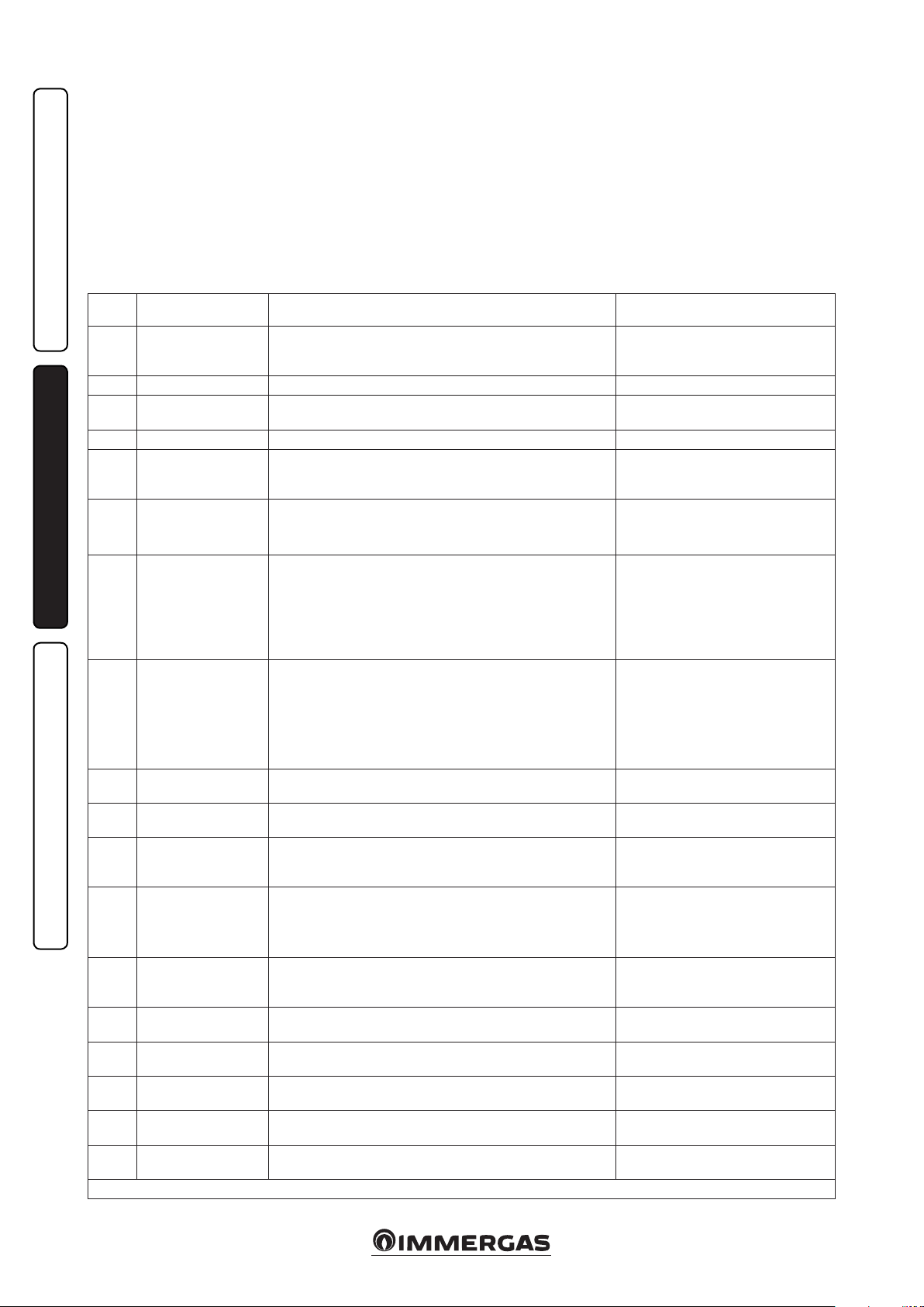
2.5 TROUBLESHOOTING.
e hydronic module signals any anomalies by
ashing a code on the display (14) according to
the following table.
Hydronic module error codes are preceded by
the letter "E", while error codes referring to
the condensing unit are preceded by the letter
"A". For the latter, refer to the condensing unit
booklet for the complete list of all the anomalies.
e CARV2 displays error codes with only the
last two digits (e.g. E184 = ERR 84).
INSTALLERUSERMAINTENANCE TECHNICIAN
Error
Code
E 2
E 5 Flow probe anomaly e board detects an anomaly on the ow NTC probe. e system does not start (1).
E 12
E 23 Return probe anomaly e board detects an anomaly on the return NTC probe e system does not start (1).
E 24
E 26
E 27 Insucient circulation
E 31
E 32
E 37
46
E 50
E 54
E 129
E 130
E177
E178
E179
(1) If the block or anomaly persists, contact an authorised company (e.g. Immergas Technical Aer-Sales Service).
Anomaly signalled Cause Hydronic module status / Solution
Safety thermostat
block (over-temperature)
Storage tank probe
anomaly
Push button control
panel anomaly
System owmeter
anomaly
Loss of communication with the CARV2
(zone 1)
Low temperature zone 2
probe anomaly
Low power supply
voltage
Low temperature safety
thermostat (optional)
External probe missing
or faulty
Central heating storage
tank probe anomaly
(optional)
Zone 1 humidity probe
anomaly
Zone 2 humidity probe
anomaly
DHW maximum time
alarm
Anti-Legionella cycle
not successful
Liquid phase probe
anomaly
During normal operation, if a fault causes excessive overheating
internally, the boiler goes into overheating block.
e board detects an anomaly on the storage tank probe
e board detects an anomaly on the pushbutton panel.
e board detects an anomaly on the system owmeter.
Return pump (optional) always working.
is happens when the hydronic module overheats due to poor water
circulation in the primary circuit. e causes can be:
- low system circulation; check that no shut-o devices are closed on
the central heating circuit and that the system is free of air (deaerated);
- pump blocked; free the pump.
is happens when an incompatible remote control is connected or
when communication between the hydronic module and CARV2 is lost.
If the board detects an anomaly on the low temperature zone 2 probe,
the system cannot work in the aected area.
is occurs when the power supply voltage is lower than the allowed
limits for correct system operation.
During normal operation, if an anomaly causes excessive overheating
of the ow temperature in the low temperature zone, the unit indicates
the malfunction.
In the event the external probe is not connected or is faulty, the
anomaly is indicated.
e central heating storage tank has an out of range resistive value Puer mode is disabled. (1)
Anomaly on the zone 1 humidity probe (optional). Zone humidity
cannot be checked.
Anomaly on the zone 2 humidity probe (optional). Zone humidity
cannot be checked.
Domestic hot water production is not met within the pre-established time
e anti-Legionella cycle is run without success within the pre-established time
e board detects an anomaly on the liquid phase NTC probe. e system does not start (1).
Press the Reset button (1)
e hydronic module is unable to produce domestic hot water (1).
If normal conditions are restored, the
system restarts without having to be reset
(1).
e system does not start (1).
Make sure the return pump (optional) only
activates when requested.
Press the Reset button (1).
Cut power to the hydronic module then
power it back on. If the Remote Control is
still not detected at restart, the system will
switch to local operating mode, i.e. using
the controls on the control panel. In this
case the “Central Heating” (1) mode cannot
be activated.
(1)
If normal conditions are restored, the system restarts without having to be reset (1)
e unit does not meet the zone central
heating requirement. (1)
Check the external probe connection.
e system continues to operate with the
external probe integrated in the condensing
unit (1).
In addition to the humidity, the dew point
is not calculated for the zone (1) either
In addition to the humidity, the dew point
is not calculated for the zone (1) either
e system continues to operate with
non-optimal performance (1)
(1)
16
Page 17
Error
Code
E181
E182 Condensing unit alarm An anomaly appears on the condensing unit
E183
E184
E188
E189
(1) If the block or anomaly persists, contact an authorised company (e.g. Immergas Technical Aer-Sales Service).
Anomaly signalled Cause Hydronic module status / Solution
Cut power to the hydronic module then
Loss of communication with the CARV2
(zone 2)
Condensing unit in test
mode
Communication error
with condensing unit
Request with temperature out of range
Time out alarm with
communication board
is happens when an incompatible remote control is connected
or when communication between the hydronic module and second
zone CARV2 is lost.
A signal noties that the condensing unit is in test mode
A signal noties an anomaly due to a communication problem
between the hydronic module and the condensing unit.
A request is made with the outdoor temperature exceeding the
operating limits (parag. 1.12)
If communication between the printed circuit boards is lost, an
anomaly is signalled.
power it back on. If the Remote Control is
still not detected at restart, the system will
switch to local operating mode, i.e. using
the controls on the control panel. In this
case the “Central Heating” (1) mode cannot
be activated.
e system does not work, see the
anomaly on the condensing unit and its
instructions booklet (1)
During this time, room heating/air conditioning and domestic hot water production requirements cannot be met
Have the electrical connection between
the units checked.
e system does not start (1).
e system does not start (1).
(1)
INSTALLERUSERMAINTENANCE TECHNICIAN
17
Page 18

2.6 PARAMETERS AND INFORMATION
MENU.
Pressing the "MENU" button (2), the display
cyclically shows the "Data" menu, "User" menu
and a menu protected by a "0000" access code
with the rst ashing digit reserved for a qualied
technician.
Data Menu.
To access an individual menu, once it appears,
press the "OK" button (1).
To scroll through the menu items and to edit the
values, use the DHW temperature regulation buttons (4). Pressing the "OK" button (1) conrms
the parameter, pressing the "ESC" button (3) goes
back to the previous menu or exits.
A minute aer the last operation, the system
automatically exits any of the menus.
INSTALLERUSERMAINTENANCE TECHNICIAN
Id
Parameter
D 03 Storage tank unit temperature 0 ÷ 99 °C
D 04 Value calculated for system setting 0 ÷ 99 °C
D 05 Value set for DHW setting 0 ÷ 99 °C
D 06
D 08 System return water temperature 0 ÷ 99 °C
D 09
D 10
D 14 Circulator ow rate
D 20 System ow temperature 0 ÷ 99 °C
D 22 DHW 3-way (DHW = domestic hot water, CH = central heating) DHW - CH
D 24 Chiller circuit liquid temperature - 20 ÷ 99 °C
D 25 Zone 2 ow temperature (if congured) 0 ÷ 99 °C
D 26 Probe for primary solar storage (puer) 0 ÷ 99 °C
D 28 System circulator instantaneous speed 0 ÷ 100 %
D 31 DHW integration function OFF - ON
D 32 System integration function OFF - ON
D 35 Solar system inlet OFF - ON
D 41 Zone 1 relative humidity 0 ÷ 99 %
D 42 Zone 2 relative humidity 0 ÷ 99 %
D 43 Zone 1 humidistat OFF - ON
D 44 Zone 2 humidistat OFF - ON
D 45 Dehumidier zone 1 OFF - ON
D 46 Dehumidier zone 2 OFF - ON
D 47 Zone 1 circulator pump OFF - ON
D 48 Zone 2 circulator pump OFF - ON
D 49 Central heating / cooling system separation 3-way (CL = cooling, HT = heating) CL - HT
D 51 Zone 1 remote control OFF - ON
D 52 Zone 2 remote control OFF - ON
D 53 System setting with remote connection in zone 1 0 ÷ 99 °C
D 54 System setting with remote connection in zone 2 0 ÷ 99 °C
D 55 Zone 1 thermostat OFF - ON
D 56 Zone 2 thermostat OFF - ON
D 61 Appliance model denition MP
D 62 Communication with outdoor condensing unit OFF - ON
D 63 Communication with other Immergas devices OFF - ON
D 71 Condensing unit operating frequency 0 ÷ 150 Hz
D 72 Condensing unit compressor temperature 0 ÷ 200 °C
D 73 Compressor outlet instantaneous temperature 0 ÷ 100 °C
D 74 Evaporator coil temperature 0 ÷ 100 °C
D 75 Condensing unit compressor absorption 0 ÷ 10 A
D 76 Condensing unit fan speed 0 ÷ 100 rpm
D 77 Electronic expansion valve position 0 ÷ 500
D 78 4-way side (CL = cooling, HT = heating) HT / CL
D 91 Soware version
Outdoor temperature (if the condensing unit external probe is connected or if the optional external probe is available)
List of the last ve anomalies.
(to scroll through the list, press the "OK" button (1))
Anomaly list reset. Once "D 10" is displayed, press the "OK" button. Deletion is conrmed via the "88" symbols
ashing for two seconds.
Description Range
- 20 ÷ 50 °C
D91 ÷ D95
0 ÷ 9999
(x 100 l/h)
-
18
Page 19

User Menu.
Id
Parameter
U 01 Zone 2 central heating setting 25 ÷ 55 °C 25
U 02 Zone 2 cooling setting 7 ÷ 25 °C 20
U 03 Zone 1 central heating oset
U 04 Zone 2 central heating oset - 15 ÷ + 15 °C 0
U 05 Zone 1 central heating oset
U 06 Zone 2 central heating oset - 15 ÷ + 15 °C 0
U 07 Zone 1 humidity setting
U 08 Zone 2 humidity setting 30 ÷ 70 °C 50
U 11 Night function
U 12 Night function enabling time 0 ÷ 23 0
U 13 Night function disabling time 0 ÷ 23 0
N.B.: the parameters referring to zone 2 can only be displayed if there is a zone 2 on the system and it is congured correctly.
2.7 SWITCHING OFF THE HYDRONIC
MODULE.
Switch o the hydronic module, putting it in
"o" mode. Switch o the omni-polar switch
outside the unit. Never leave the unit powered if
le unused for prolonged periods.
2.8 RESTORING CENTRAL HEATING
SYSTEM PRESSURE.
Periodically check the system water pressure.
e hydronic module pressure gauge must show
a value between 1 and 1.2 bar.
If the pressure is less than 1 bar (with the system
cold), you must restore it using the cock located at
the bottom of the unit (Fig. 1-3).
N.B.: close the cock aer the operation.
If pressure values reach around 3 bar the safety
valve may be activated.
In this case, remove water from an air vent valve
of a radiator until reaching pressure of 1 bar, or
ask for assistance from professionally qualied
personnel.
In the event of frequent pressure drops, contact
qualified staff for assistance to eliminate the
possible system leakage.
2.9 SYSTEM DRAINING.
To drain the hydronic mdule, use the special
drain tap (Fig. 1-3).
Before draining, ensure that the lling cock is
closed.
Description Range Default
You can edit the ow temperature with respect to the
external probe regulation curve in central heating
mode (Fig. 1-xx Oset value)
You can edit the ow temperature with respect to the
external probe regulation curve in cooling mode (Fig.
1-xx Oset value)
e humidity temperature sensor (optional) denes
room humidity in the corresponding area
is function can only be activated if CARV2 (optional)
is available
Activating the function allows you to disable condensing
unit operation during the time slot set in the U 12 and
U 13 parameters.
Make sure the additional power sources needed to meet
potential requirements that may present themselves
during active operation are available (e.g. additional
resistances)
2.10 ANTIFREEZE PROTECTION.
e hydronic module has an anti-freeze function
that automatically switches on the condensing
unit when the temperature drops below 4°C
(standard protection up to a minimum temperature of -5°C). All information relative to the
anti-freeze protection is stated in Par. 1.3. In
order to guarantee the integrity of the appliance
and the domestic hot water heating system in
areas where the temperature drops below zero,
we recommend protecting the central heating
system using anti-freeze liquid and installing the
Immergas Anti-freeze Kit in the hydronic module. In the case of prolonged inactivity (second
case), we also recommend that:
- disconnect the electric power supply;
- completely empty the central heating circuit
and the hydronic module domestic hot water
circuit. In systems that are drained frequently,
lling must be carried out with suitably treated
water to eliminate hardness that can cause limescale.
2.11 CASE CLEANING.
Use damp cloths and neutral detergent to clean
the hydronic module casing. Never use abrasive
or powder detergents.
- 15 ÷ + 15 °C 0
- 15 ÷ + 15 °C 0
30 ÷ 70 °C 50
OFF - ON OFF
2.12 DECOMMISSIONING.
Should the system be shut down permanently,
have professional sta carry out the procedures,
making sure that the electrical and water supply
lines have been previously shut o.
Value
range
INSTALLERUSERMAINTENANCE TECHNICIAN
19
Page 20

COMMISSIONING THE
3
PACKAGE INITIAL
CHECK
To commission the package, you must:
- make sure that the declaration of conformity
for installation is supplied with the appliance;
- check connection to a 230V-50Hz power
mains, correct L-N polarity and the earthing
connection;
- make sure the central heating system is lled
INSTALLERUSERMAINTENANCE TECHNICIAN
with water and the hydronic module pressure
gauge reads a pressure of 1÷1.2 bar;
- make sure the chiller circuit has been lled
3.1 HYDRONIC MODULE HYDRAULIC DIAGRAM
according to what is described in the Audax
Pro condensing unit instructions booklet;
- check the operation of the main switch located
upstream of and on the hydronic module.
- ensure activation of all adjustment devices;
- check the production of domestic hot water;
- check sealing eciency of water circuits;
Even if just one single safety check provides a
negative result, do not commission the system.
Key:
1 - System cut-o tap
2 - 3 bar safety valve
3 - Hydronic unit circulator
4 - Vent valve
5 - System draining valve
6 - Liquid phase detection probe
7 - System ow meter
8 - System expansion vessel
9 - Return probe
10 - Plate heat exchanger
11 - Vent valve
12 - Central heating integrated electric
resistance (optional)
13 - Central heating manifold
14 - Flow probe
15 - System lling cock
16 - ree-way valve (motorised)
17 - By-pass
18 - System with inspectable lter cut-o
tting
19 - System cut-o tap
3-1
LP - Chiller line - liquid phase
GP - Chiller line - gaseous phase
RU - Storage tank unit return
MU - Storage tank unit ow
RR - System lling
R - System return
M - System ow
20
Page 21

3.2 WIRING DIAGRAM.
INSTALLERUSERMAINTENANCE TECHNICIAN
CONDENSING UNIT
230 Vac
230 Vac
SOLAR
DHW
FUNCTION
INTEGRAT-
BLING
HEAT PUMP DISA-
TEMS FROM 3 KW
ANCE KIT FOR SYS-
INTEGRATED RESIST-
50 Hz
RIES
AUXILIA-
CONTROL
ED RESIST.
BUS
ING UNIT
CONDENS-
3-2A
21
Colour code key:
BK - Black
BL - Blue
BR - Brown
G - Green
GY - Grey
OR - Orange
P - Purple
PK - Pink
R - Red
W - White
Y - Yellow
agement (optional)
Key:
A3 - P.C.B.
A7 - Congurable relay board (optional)
A16-1 - Zone 1 dehumidier (optional)
A16-2 - Zone 2 dehumidier (optional)
A19 - Two relay board for dehumidier man-
A22 - Heat pump communication board
M1-2 - System circulator pump
M10-1 - Zone 1 circulator (optional)
M10-2 - Zone 2 circulator (optional)
M31-2 - Zone 2 mixing valve (optional)
M52 - Hot cold three-way (optional)
T1 - Transformer
Page 22

INSTALLERUSERMAINTENANCE TECHNICIAN
BL - Blue
BR - Brown
G - Green
GY - Grey
OR - Orange
P - Purple
PK - Pink
R - Red
W - White
Y - Yellow
is disconnected, the
V2
also be connected, put in a
V2
connecting the S20-1 room thermostat.
X40-1 jumper must be kept available
jumper between terminals 40-2 and 41-2
connect the congurable relay board.
relay board.
with other Immergas appliances.
R8 - Storage tank function unabling resistance
R14 - Conguration resistance
S20-1 - Zone 1 room thermostat (optional)
S20-2 - Zone 2 room thermostat (optional)
S36-1 - Zone 1 humidistat (optional)
S36-2 - Zone 2 humidistat (optional)
X40-1 - Zone 1 room thermostat jumper
Notes: - Eliminate the X40-1 jumper before
- When the CAR
- Should CAR
- e Y3 and Y5 connectors can be used to
- e Y6 connector is used to connect the 2
- T+ / T- (RS485): bus for communication
Colour code key:
BK - Black
remote control (optional)
remote control (optional)
(optional)
-1 - Zone 1 V2 Comando Amico Remoto
-2 - Zone 2 V2 Comando Amico Remoto
V2
V2
Key:
A3 - P.C.B.
A17-1 - Zone 1 humidity sensor (optional)
A17-2 - Zone 2 humidity sensor (optional)
A22 - Heat pump communication board
B1 - Flow probe
B2 - Domestic hot water probe (optional)
B3-2- Zone 2 ow probe (optional)
B4 - External probe (optional)
B5 - Return probe
B13 - Puer central heating probe (optional)
B25 - System ow meter
B27 - Liquid phase probe
CAR
CAR
E7 - Low temperature safety thermostat
M1-2 - System circulator pump
M50 - Priority 3-way valve
COMMUNICATION
OPTIONAL RS485
3-2B
22
Page 23

3.3 SYSTEM FILTER.
e hydronic module has a lter on the system
return tting to keep the system in good operating conditions.
Periodically and when necessary, the lter can be
cleaned as described below (Fig. 3-4).
Close the tap (4) and the tap (3) with a 12mm
spanner, drain the water contents in the hydronic
module using the drain tap (4).
Open the cap (1) and clean the lter (2).
P.C.B.
3.4 TROUBLESHOOTING.
N.B.: maintenance interventions must be carried
out by an authorised company (e.g. Immergas
Aer-Sales Technical Assistance Service).
- Noise due to air in the system. Check opening
of the special air vent valve cap (Part. 7 and 12
Fig. 1-11). Make sure the system pressure and
expansion vessel pre-charge values are within
the set limits; e factory-set pressure values of
the expansion vessel must be 1.0 bar, the value
of system pressure must be between 1 and 1.2
bar.
INSTALLERUSERMAINTENANCE TECHNICIAN
Communication P.C.B.
Key:
1 - T 3.5 A fuse
2 - T 5.0 A fuse
3-3
1
2
3
4
5
23
3-4
Page 24

3.5 PROGRAMMING THE P.C.B.
The water heater is set up for possible programming of several operation parameters.
By modifying these parameters as described
below, the system can be adapted according to
specic needs.
To access the programming phase, press the
INSTALLERUSERMAINTENANCE TECHNICIAN
Id
Parameter
A 03
A 04
A 11
A 12 System vent
A 13
A 16
A 17
A 21
A 22
Parameter Description Range Default
Minimum
speed
Maximum
xed speed
Condensing
unit model
Number of
zones
Zone 1 humid-
ity sensor
Zone 2 humid-
ity sensor
BMS com-
munication
address
BMS com-
munication
setting
Denes the minimum operating speed of the system
circulator
Denes the maximum operating speed of the system
circulator
Establishes the condensing unit model paired with the
hydronic module.
If set to OFF, only the integrated generators are activated.
Enables the automatic vent function.
is function activates as soon as the unit is powered.
Denes the number of zones in the heating system 1 - 2 1
Humidity temperature sensor / Humidistat
Denes the type of control on zone 1 humidity
Humidity temperature sensor / Humidistat
Denes the type of control on zone 2 humidity
Denes the communication protocol between the hydronic module and the condensing unit
OFF = BMS communication protocol on 485; use if connected to optional Immergas devices.
485 = Do not use
UC = Do not use
"MENU" button (2) until the "Password" menu
appears. Enter the password, modify the numerical values using the "DHW regulation" buttons
(5) and conrm with the "OK" button (1).
Once you have accessed programming, you can
scroll through the parameters in the "System"
menu.
Using the "DHW regulation" button, select the
parameter and edit the value.
0 ÷ 99 % 100
0 ÷ 99 % 100
OFF - 5 - 8 - 10 8
OFF - ON ON
SE = Humidity temp. sensor
ST = Humidistat
SE = Humidity temp. sensor
ST = Humidistat
1 ÷ 247 11
OFF - 485 - UC OFF
To save the parameter change, press the "OK"
button.
Wait for 1 minute or press the "ESC" button (3)
to exit programming mode.
Customised
value
ST
ST
Id
Parameter
P 03
P 04
P 05
P 06
P07
Parameter Description Range Default
e hydronic module is set up to operate with a congurable relay
board (optional)
Relay 1
(optional)
Relay 2
(optional)
Relay 3
(optional)
Pump func-
tioning
External probe
correction
0 = O
1 = DHW recirculation
2 =General alarm
3 = Central heating / cooling phase active
4 = Puer mode active
e hydronic module is set up to operate with a congurable relay
board (optional)
0 = O
1 = DHW recirculation
2 =General alarm
3 = Central heating / cooling mode active
4 = Puer mode active
e hydronic module is set up to operate with a congurable relay
board (optional)
0 = O
1 = DHW recirculation
2 =General alarm
3 = Central heating / cooling mode active
4 = Puer mode active
e pump can function in two ways.
IN (intermittent): in "winter" mode, the circulator is managed by the
room thermostat or by the remote control
CO (continuous): in "winter" and "cooling" mode, the circulator is always
powered and is, therefore, always in operation
If the reading of the external probe is not correct it is possible to correct
it in order to compensate any environmental factors.
(Over the value of +9 the display shows “CE”, which enables an external
control function of the boiler for coupling of the same with a system
supervisor)
0 ÷ 4 0
0 ÷ 4 0
0 ÷ 4 0
IN - CO IN
-9 ÷ 9 K 0
Customised
value
24
Page 25

Id
Parameter
T 02 DHW thermostat
T 05
T 07
T 08 Display lighting
T 09 Display
Parameter Description Range Default
Central heating
ignitions timer
Delay request
fr om TA
Establishes the unit ignition and switch-o mode in DHW mode.
It is enabled when the water in the storage tank goes below the DHW set
value and is disabled when the temperature exceeds the DHW set value.
e hydronic module has an electronic timer, which prevents the generator from igniting too oen in central heating mode
e system is set to switch on immediately aer a request for room heating/
air conditioning. For special systems (e.g. zone systems with motorised valves,
etc.), it may be necessary to delay ignition.
Establishes the display lighting mode.
AU: the display lights up during use and lowers aer 15 seconds of inactivity.
In the event of an anomaly, the display ashes.
OFF: the display lighting is always o.
ON: the display lighting is always on.
Establishes what the indicator displays 14 (Fig. 2-1).
"Summer" mode:
ON: circulator active, displays the ow temperature
pump o the indicator is o
OFF: the indicator is always o
"Winter" and "cooling" mode:
ON: circulator active, displays the ow temperature
circulator o, displays the value set on the central heating selector.
OFF: always displays the value set on the central heating selector
0 ÷ 20 °C 4
0 - 10 min-
utes
0 - 240
seconds
(step 10 sec)
AU - OFF
- ON
ON - OFF ON
Customised
value
3
0
INSTALLERUSERMAINTENANCE TECHNICIAN
AU
25
Page 26
Heat regulation menu.
INSTALLERUSERMAINTENANCE TECHNICIAN
Id
Parameter
R 01 External probe
R 02
R 03
R 04
R 05
R 06
R 07
R 08
R 09
R 10
R 11
R 12
R 13
R 14
R 15
R 16
R 17
Parameter Description Range Default
Outdoor temper-
ature for max CH
ow
Outdoor temperature for min CH
ow
Maximum cen-
tral heating
Minimum central
heating
Outdoor tem-
perature for low
temperature zone
max CH ow
Outdoor tem-
perature for low
temperature zone
min CH ow
Low temperature
zone maximum
central heating
Low temperature
zone minimum
central heating
Outdoor
temperature
for minimum
cooling ow
Outdoor
temperature
for maximum
cooling ow
Minimum
cooling
Maximum
cooling
Outdoor
temperature for
low temperature
zone minimum
cooling ow
Outdoor tem-
perature for low
temperature zone
max cooling ow
Low temperature
zone minimum
cooling
Low temperature
zone maximum
cooling
Denes if and which external probe is used to manage the system.
OFF = no external probe used
OU = external probe on the condensing unit
IU = optional external probe connected to the hydronic module
Establishes the outdoor temperature at which to have the maximum ow
temperature.
Establishes the outdoor temperature at which to have the minimum ow
temperature.
Denes the maximum ow temperature in room central heating mode 35 ÷ 55 45
Denes the minimum ow temperature in room central heating mode 25 ÷ 55 25
Establishes the outdoor temperature at which to have the maximum ow
temperature in the low temperature zone
Establishes the outdoor temperature at which to have the minimum ow
temperature in the low temperature zone
Denes the maximum ow temperature in room central heating mode in
the low temperature zone
Denes the minimum ow temperature in room central heating mode in
the low temperature zone
Establishes the maximum outdoor temperature at which to have the minimum ow temperature in cooling mode
Establishes the minimum outdoor temperature at which to have the maximum ow temperature in cooling mode
Denes the minimum ow temperature in room cooling mode 07 ÷ 20 7
Denes the maximum ow temperature in room cooling mode 10 ÷ 25 12
Establishes the outdoor temperature at which to have the minimum ow
temperature in the low temperature zone
Establishes the outdoor temperature at which to have the maximum ow
temperature in the low temperature zone
Denes the minimum ow temperature in room cooling mode in the low
temperature zone
Denes the maximum ow temperature in room cooling mode in the low
temperature zone
OFF - OU
- IU
-15 ÷ 25 °C -5
-15 ÷ 25 °C 25
-15 ÷ 25 °C -5
-15 ÷ 25 °C 25
35 ÷ 55 35
25 ÷ 35 25
20 ÷ 40 35
20 ÷ 40 25
20 ÷ 40 35
20 ÷ 40 25
07 ÷ 20 18
10 ÷ 25 20
OU
Customised
value
26
Page 27
Integration menu.
Id
Parameter
I 01
I 02
I 03
I 04
I 08
Maintenance menu.
Accessing this menu, the unit goes into standby. By selecting every single parameter, you can
activate a specic function for each load.
Parameter Description Range Default
DHW integration
enabling
System integra-
tion enabling
DHW max wait
time
Central heating
max wait time
Activation tem-
perature
Allows you to enable an alternative power source (AL) to integrate domestic
hot water heating.
Using this function, you can enable an alternative (AL) or simultaneous (CO)
power source to integrate heating system central heating.
Establishes the maximum amount of time before activating DHW integration.
Establishes the maximum amount of time before activating central heating
integration.
Establishes the outdoor temperature under which central heating integration
is enabled.
OFF - AL OFF
OFF - AL
- CO
0 - 900
minutes
(10 minute
intervals)
0 - 900
minutes
(10 minute
intervals)
-15 ÷ 20 °C -5
OFF
Customised
value
30
INSTALLERUSERMAINTENANCE TECHNICIAN
45
Id
Parameter
M 01 Venting
M 02
M 03 DHW 3-way Moves the 3-way motor from system to DHW OFF - ON OFF
M 04 Cooling 3-way Moves the cooling circuit 3-way motor OFF - ON OFF
M 08
M 09
M 10 Mixer zone 2 Establishes zone 2 mixing valve positioning
M 11
M 12
M 13
M 14
M 15 Relay 1 Enables relay 1 on the 3-relay board OFF - ON OFF
M 16 Relay 2 Enables relay 2 on the 3-relay board OFF - ON OFF
M 17 Relay 3 Enables relay 3 on the 3-relay board OFF - ON OFF
Parameter Description Range Default
In the case of new central heating systems and in particular mode for oor
systems, it is very important that dearation is performed correctly. e
function consists of the cyclic activation of the pump (100 s ON, 20 s OFF)
System circulator
speed
Zone 1 outdoor
circulator
Zone 2 outdoor
circulator
DHW electrical
resistance
Central heating
electrical resist-
ance
Dehumidier
zone 1
Dehumidier
zone 2
and the 3-way valve (120 s D.H.W., 120 s heating system).
e function lasts for 18 hours and can be interrupted by pressing the "ESC"
button and setting the function to "OFF"
Activation of the function is signalled by the countdown shown on the
indicator (14).
Establishes the system circulator speed 0 - 100% 0
Enables the zone 1 outdoor circulator OFF - ON OFF
Enables the zone 2 outdoor circulator OFF - ON OFF
Enables the DHW integrated electrical resistance OFF - ON OFF
Enables the room central heating integrated electrical resistance OFF - ON OFF
Enables the dehumidier in zone 1 OFF - ON OFF
Enables the dehumidier in zone 2 OFF - ON OFF
OFF - ON OFF
OFF
- OPEN CLOSE
Customised
value
OFF
27
Page 28

3.6 PUMP ANTILOCK FUNCTION
e hydronic module has a function that starts
up the pump at least once every 24 hours for 30
seconds in order to reduce the risk of the pump
locking up due to prolonged inactivity.
3.7 3WAY ANTILOCK FUNCTION
Both in "DHW" and in "DHW-system central
heating" mode, the hydronic module has a function that activates the motorised 3-way unit 24
hours aer the last time it operated by running
a complete cycle in order to reduce the risk of
INSTALLERUSERMAINTENANCE TECHNICIAN
the 3-way locking up due to prolonged inactivity.
3.8 RADIATOR ANTIFREEZE
FUNCTION.
If the system return water is below 4°C, the
hydronic module starts up until it reaches 42°C.
3.9 SOLAR FUNCTION.
If the solar inlet is active, any accumulated DHW
is heated to 50°C.
3.10 OUTDOOR UNIT DISABLE
FUNCTION.
With the inlet active, outdoor unit operation is
inhibited.
3.11 DIVERTER VALVE MANAGEMENT
SUMMER / WINTER.
e unit electronics has a 230V outlet to manage
the summer / winter diverter valves. e switch
occurs when the mode (summer / winter) is
changed from the control panel or from the
CARV2.
3.14 YEARLY APPLIANCE CHECK AND
MAINTENANCE.
e following checks and maintenance should
be performed at least once a year.
- Visually check for water leaks or oxidation
from/on connections.
- Aer discharging system pressure and bringing
it to zero (read on the hydronic module pressure gauge), make sure the expansion vessel
pressure is at 1.0 bar.
- Check that the system static pressure (with
system cold and aer relling the system by
means of the lling cock) is between 1 and 1.2
bar.
- Visually check that the safety and control
devices have not been tampered with and/or
short-circuited.
- Check the condition and integrity of the elec-
trical system and in particular:
- supply voltage cables must be inside the
fairleads;
- there must be no traces of blackening or
burning.
- Check ignition and operation.
- Check the operation of the appliance control
and adjustment devices and in particular:
- system regulation probes intervention;
IMPORTANT NOTE: in addition to yearly
maintenance, you must also check the heating
system and energy eciency, with the frequency
and procedures that comply with the technical
regulations in force.
3.12 ANTILEGIONALLA FUNCTION.
With the integrated DHW resistance, the function can be activated using the CARV2.
See the instructions booklet to congure the
function.
3.13 AUTOMATIC VENT FUNCTION.
In the case of new central heating systems and
in particular mode for oor systems, it is very
important that dearation is performed correctly.
e function consists of the cyclic activation of
the pump (100 s ON, 20 s OFF) and the 3-way
valve (120 s D.H.W., 120 s C.H.).
e function is activated in two dierent ways:
- each time the hydronic module is re-powered;
- by pressing the buttons at the same time (3
and 5 Fig. 2-1) for 5 seconds with the hydronic
module in stand-by.
N.B.: if the hydronic module is connected to
the CARV2, the "stand-by" function can only be
enabled from the remote control panel.
In the rst case, the function has a duration of
8 minutes and it can be interrupted by pressing
the “reset” button (2). In the second case, it has
a duration of 18 hours and it can be interrupted
simply by switching the hydronic module on.
Activation of the function is signalled by the
countdown shown on the indicator (14).
28
Page 29
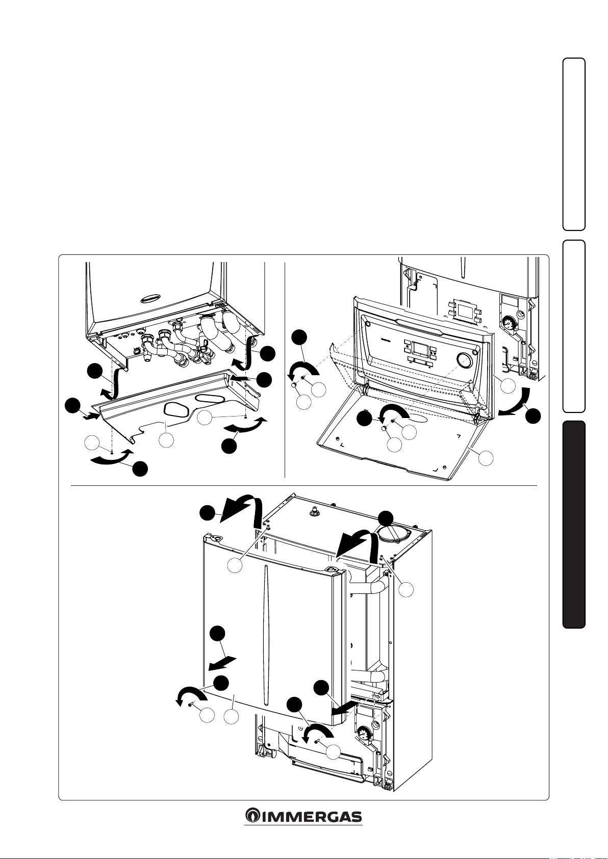
3.15 CASING REMOVAL.
To facilitate hydronic module maintenance, the
casing can be completely removed as follows:
• Lower grid (Fig. 3-5a).
1) Loosen the two screws (a);
2) Press the hooks inwards, which block the
lower grid (b).
3) remove the grid (b).
• Front panel (Fig. 3-5b).
4) Open the protection door (e1) pulling it
towards you.
5) Remove the cover caps (c) and loosen screws
(d).
6) Pull the front panel (e) towards you and
release it from its lower seat.
• Front (Fig. 3-5c).
7) Loosen the two screws (g).
8) Pull the front (f) slightly towards you.
9) Release front (f) from pins (h) pulling it
towards you while pushing it upwards at the
same time.
3
3
2
2
a
a
3-5a 3-5b
b
1
1
INSTALLERUSERMAINTENANCE TECHNICIAN
4
d
c
4
d
c
e
5
e1
3-5c
8
8
h
h
7
6
7
6
g
f
g
29
Page 30
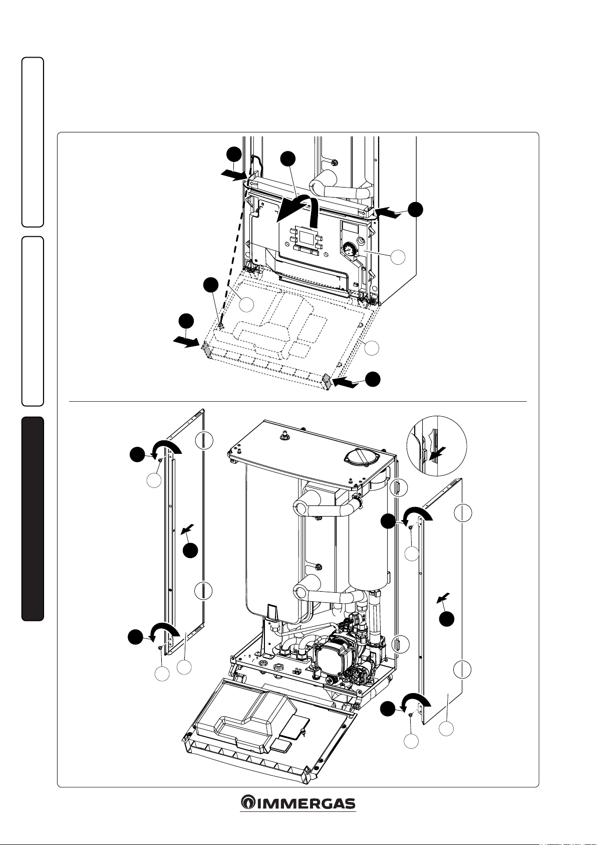
Rif. X
• Control panel (Fig. 3-5d).
9) Press the hooks on the side of the control
panel (i).
10) Tilt the control panel (i) towards you.
e control panel (i) can rotate until the
support cord (j) is completely extended.
11) If the le side needs to be removed, unhook
the support cord (j) from the control panel
and proceed as follows.
• Sides (Fig. 3-5e).
12) Unscrew the side (k) fastening screws (l).
13) Remove the sides by extracting them from
their rear seat (Rif. X).
INSTALLERUSERMAINTENANCE TECHNICIAN
3-5d
9
10
9
i
11
j
9
i
9
Ref. X
12
12
X
l
X
X
12
13
l
X
13
X
A
k
l
12
k
l
3-5e
30
Page 31
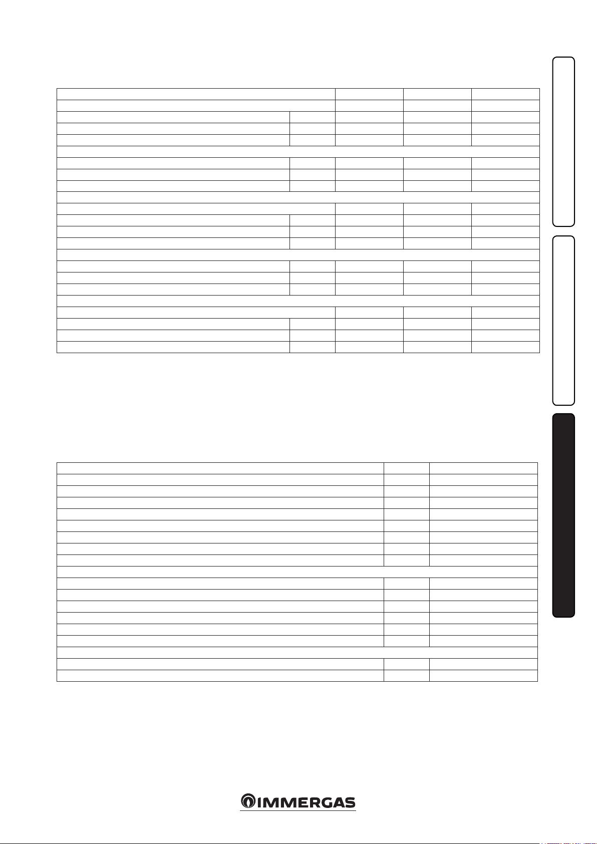
3.16 TECHNICAL DATA.
The data below refer to the pairing between
hydronic module and Audax Pro.
Magis Pro 5 ErP Magis Pro 8 ErP Magis Pro 10 ErP
Nominal data for low temperature applications *
Nominal central heating output kW 5.80 7.71 9.80
Absorption kW 1.28 1.89 2.39
COP kW/kW 4.53 4.08 4.10
Nominal cooling output kW 6.03 7.58 7.58
Absorption kW 1.67 2.01 2.01
EER kW/kW 3.61 3.77 3.77
Nominal output for average temperature applications **
Nominal central heating output kW 5.30 7.26 9.27
Absorption kW 1.55 2.32 2.98
COP kW/kW 3.42 3.13 3.11
Nominal cooling output kW 4.90 5.38 7.31
Absorption kW 1.87 2.26 3.07
EER kW/kW 2.62 2.38 2.38
Nominal output for high temperature applications **
Nominal central heating output kW 4.80 6.17 8.45
Absorption kW 1.82 2.64 3.59
COP kW/kW 2.64 2.34 2.35
* Central heating mode status: heat exchanger water inlet/remains at 30 °C/35 °C, outdoor air temperature 7 °C db/6 °C wb. Performance in compliance
with EN 14511.
Cooling mode status: heat exchanger water inlet/remains at 23 °C/18 °C, outdoor air temperature 35 °C. Performance in compliance with EN 14511.
** Central heating mode status: heat exchanger water inlet/remains at 40 °C/45 °C, outdoor air temperature 7 °C db/6 °C wb.
Cooling mode status: heat exchanger water inlet/remains at 12 °C/7 °C, outdoor air temperature 35 °C. Performance in compliance with EN 14511.
*** Central heating mode status: inlet/remains at 47 °C/55 °C, outdoor air temperature 7 °C db/6 °C wb. Performance in compliance with EN 14511.
INSTALLERUSERMAINTENANCE TECHNICIAN
Hydronic module data.
Hydraulic circuit max. operating pressure bar 3
Maximum central heating temperature °C 70
Adjustable central heating temperature (max operating eld) °C 25 - 55
Head available with 1000 l/h ow rate kPa (m c.a.) 44.2 (4.5)
Domestic hot water adjustable temperature °C 30 - 65
Water content l 4.0
Expansion vessel volume l 12.0
Expansion vessel factory-set pressure bar 1.0
Hydraulic circuit maximum pressure kPa 300
Electrical connection V/Hz 230 / 50
Absorption without additional loads W 65
Maximum absorption with loads W 170
Integrated resistance absorption (optional) kW 3
EEI value - ≤ 0.20 - Part. 3
Equipment electrical system protection - IPX4D
Empty hydronic unit weight kg 33.5
Full hydronic unit weight kg 37.5
31
Page 32

3.17 PRODUCT FICHE IN COMPLIANCE WITH REGULATION 811/2013.
Low temperature (30/35)
Parameter Val ue
Annual energy consumption for the central
heating function (QHE)
Room central heating
seasonal eciency (ηs)
++
A
Nominal heat output kW 7.80 5.50 6.00
Average temperature (47/55)
Parameter Val ue
Annual energy consumption for the central
heating function (QHE)
Room central heating
seasonal eciency (ηs)
Nominal heat output kW 7.70 6.20 5.40
D
E
F
G
MAGIS PRO 5 ERP
55 °C 35 °C
++
A
A
+
A
B
A
C
B
C
D
E
F
G
+
A
7,70 7,80
6,20 5,50
For proper installation of the appliance refer to chapter 1 of this booklet (for the installer)
and current installation regulations. For proper maintenance refer to chapter 3 of this booklet
(for the maintenance technician) and adhere to the frequencies and methods set out herein.
dB
5,40 6,00
kW kW
Colder zones
kWh/year 5870 2891 1559
ηs % 162 154 201
Colder zones
kWh/year 8100 4435 2119
ηs % 91 112 132
Average
zones
Average
zones
Hotter zones
Hotter zones
62
dB
32
32
Page 33

Low temperature table (30/35) colder zones
Model: Magis Pro 5 ErP
Air/water heat pump: yes
Water/water heat pump: no
Brine/water heat pump: no
Low temperature heat pump: yes
With additional central heating device: no
Mixed central heating device with heat pump: no
e parameters are declared for average temperature application, except for low temperature heat pumps. e parameters for low temperature heat
pumps are declared for low temperature application
e parameters are declared for colder climatic conditions.
Element Symbol Va lue Unit Element Symbol Val ue Unit
Nominal heat output
Nominal
output
7.80 kW
Central heating capacity declared with a partial load and indoor
temperature equivalent to 20°C and outdoor temperature Tj
Room central heating seasonal energy eciency
η
s
162 %
Performance coecient declared with indoor temperature equivalent
to 20°C and outdoor temperature TJ
Tj = –7°C Pdh 5.2 kW Tj = –7°C COPd 2.83 -
Tj = +2°C Pdh 4.8 kW Tj = +2°C COPd 4.13 -
Tj = +7°C Pdh 6.3 kW Tj = +7°C COPd 6.07 -
Tj = 12°C Pdh 6.6 kW Tj = 12°C COPd 5.86 -
Tj = bivalent temperature Pdh 4.8 kW Tj = bivalent temperature COPd 2.76 -
Tj = temperature operating
limit
Pdh 4.2 kW
for air/water heat pumps: Tj
= –15°C
Pdh kW
(if TOL < –20°C)
Bivalent temperature T
Central heating capacity cycle
intervals
-8 °C
biv
Pcych kW Cycle intervals eciency
Degradation coecient Cdh 1.0 —
Tj = temperature operating
limit
for air/water heat pumps: Tj
= –15°C
(if TOL < –20°C)
for air/water heat pumps: temperature operating limit
Water heating temperature
operating limit
COPd 2.03 -
COPd -
TOL -20 °C
COPcyc or
PERcyc
-
WTOL 40 °C
Dierent mode of energy consumption from the active mode Additional heating appliance
OFF mode P
OFF
0.000 kW Nominal heat output Psup 7.80 kW
ermostat mode o PTO 0.015 kW
Type of energy supply voltage electricalStandby mode P
Guard heating mode P
SB
CK
0.015 kW
0.015 kW
Other items
Capacity control Var iable
Indoor/outdoor sound level L
Annual energy consumption Q
WA
HE
N/A dB
5870
kWh or
GJ
For air/water heat pumps:
nominal air output to outside
For water or brine/water heat
pumps: nominal ow of brine or
water, outdoor heat exchanger
— m3/h
— m3/h
For mixed central heating appliances with a heat pump
Stated load prole
Daily electrical power consumption
Q
elec
kWh Daily fuel consumption Q
Water central heating energy
eciency
η
wh
fuel
%
kWh
annual energy consumption AEC kWh Annual fuel consumption AFC GJ
Contact information Immergas s.p.a via Cisa Ligure n.95
3333
Page 34

Low temperature table (30/35) average zones
Model: Magis Pro 5 ErP
Air/water heat pump: yes
Water/water heat pump: no
Brine/water heat pump: no
Low temperature heat pump: yes
With additional central heating device: no
Mixed central heating device with heat pump: no
e parameters are declared for average temperature application, except for low temperature heat pumps. e parameters for low temperature heat
pumps are declared for low temperature application
e parameters are declared for average climatic conditions.
Element Symbol Val ue Unit Element Symbol Val ue Unit
Nominal heat output
Nominal
output
5.50 kW
Central heating capacity declared with a partial load and indoor
temperature equivalent to 20°C and outdoor temperature Tj
Room central heating seasonal energy eciency
η
s
154 %
Performance coecient declared with indoor temperature equivalent
to 20°C and outdoor temperature TJ
Tj = –7°C Pdh 5.1 kW Tj = –7°C COPd 2.55 –
Tj = +2°C Pdh 4.7 kW Tj = +2°C COPd 3.77 –
Tj = +7°C Pdh 6.2 kW Tj = +7°C COPd 5.64 –
Tj = 12°C Pdh 6.6 kW Tj = 12°C COPd 5.86 –
Tj = bivalent temperature Pdh 4.9 kW Tj = bivalent temperature COPd 2.54 –
Tj = temperature operating
limit
Pdh 5.5 kW
for air/water heat pumps: Tj
= –15°C
Pdh kW
(if TOL < –20°C)
Bivalent temperature T
Central heating capacity cycle
intervals
-7 °C
biv
Pcych kW Cycle intervals eciency
Degradation coecient Cdh 1.0 –
Tj = temperature operating
limit
for air/water heat pumps: Tj
= –15°C
(if TOL < –20°C)
for air/water heat pumps: temperature operating limit
Water heating temperature
operating limit
COPd 2.36 –
COPd –
TOL -10 °C
COPcyc or
PERcyc
–
WTOL 40 °C
Dierent mode of energy consumption from the active mode Additional heating appliance
OFF mode P
OFF
0.000 kW Nominal heat output Psup 0.62 kW
ermostat mode o PTO 0.015 kW
Type of energy supply voltage electricalStandby mode P
Guard heating mode P
SB
CK
0.015 kW
0.015 kW
Other items
Capacity control Var iable
Indoor/outdoor sound level L
Annual energy consumption Q
WA
HE
62 dB
2891
kWh or
GJ
For air/water heat pumps:
nominal air output to outside
For water or brine/water heat
pumps: nominal ow of brine or
water, outdoor heat exchanger
— m3/h
— m3/h
For mixed central heating appliances with a heat pump
Stated load prole
Daily electrical power consumption
Q
elec
kWh Daily fuel consumption Q
Water central heating energy
eciency
η
wh
fuel
%
kWh
annual energy consumption AEC kWh Annual fuel consumption AFC GJ
Contact information Immergas s.p.a via Cisa Ligure n.95
3434
Page 35

Low temperature table (30/35) hotter zones
Model: Magis Pro 5 ErP
Air/water heat pump: yes
Water/water heat pump: no
Brine/water heat pump: no
Low temperature heat pump: yes
With additional central heating device: no
Mixed central heating device with heat pump: no
e parameters are declared for average temperature application, except for low temperature heat pumps. e parameters for low temperature heat
pumps are declared for low temperature application
e parameters are declared for hotter climatic conditions.
Element Symbol Val ue Unit Element Symbol Val ue Unit
Nominal heat output
Nominal
output
6.00 kW
Central heating capacity declared with a partial load and indoor
temperature equivalent to 20°C and outdoor temperature Tj
Room central heating seasonal energy eciency
η
s
201 %
Performance coecient declared with indoor temperature equivalent
to 20°C and outdoor temperature TJ
Tj = –7°C Pdh - kW Tj = –7°C COPd - –
Tj = +2°C Pdh 4.6 kW Tj = +2°C COPd 3.31 –
Tj = +7°C Pdh 6.0 kW Tj = +7°C COPd 5.06 –
Tj = 12°C Pdh 6.6 kW Tj = 12°C COPd 5.89 –
Tj = bivalent temperature Pdh 5.7 kW Tj = bivalent temperature COPd 3.67 –
Tj = temperature operating
limit
Pdh 4.6 kW
for air/water heat pumps: Tj
= –15°C
Pdh kW
(if TOL < –20°C)
Bivalent temperature T
Central heating capacity cycle
intervals
4 °C
biv
Pcych kW Cycle intervals eciency
Degradation coecient Cdh 1.0 —
Tj = temperature operating
limit
for air/water heat pumps: Tj
= –15°C
(if TOL < –20°C)
for air/water heat pumps: temperature operating limit
Water heating temperature
operating limit
COPd 3.31 –
COPd –
TOL 2 °C
COPcyc or
PERcyc
–
WTOL 55 °C
Dierent mode of energy consumption from the active mode Additional heating appliance
OFF mode P
OFF
0.015 kW Nominal heat output Psup 1.40 kW
ermostat mode o PTO 0.015 kW
Type of energy supply voltage electricalStandby mode P
Guard heating mode P
SB
CK
0.015 kW
0.015 kW
Other items
Capacity control Var iable
Indoor/outdoor sound level L
Annual energy consumption Q
WA
HE
N/A dB
kWh or
1559
GJ
For air/water heat pumps:
nominal air output to outside
For water or brine/water heat
pumps: nominal ow of brine or
water, outdoor heat exchanger
— m3/h
— m3/h
For mixed central heating appliances with a heat pump
Stated load prole
Daily electrical power consumption
Q
elec
kWh Daily fuel consumption Q
Water central heating energy
eciency
η
wh
fuel
%
kWh
annual energy consumption AEC kWh Annual fuel consumption AFC GJ
Contact information Immergas s.p.a via Cisa Ligure n.95
3535
Page 36

Average temperature table (47/55) colder zones
Model: Magis Pro 5 ErP
Air/water heat pump: yes
Water/water heat pump: no
Brine/water heat pump: no
Low temperature heat pump: no
With additional central heating device: no
Mixed central heating device with heat pump: no
e parameters are declared for average temperature application, except for low temperature heat pumps. e parameters for low temperature heat
pumps are declared for low temperature application
e parameters are declared for colder climatic conditions
Element Symbol Val ue Unit Element Symbol Val ue Unit
Nominal heat output
Nominal
output
7.70 kW
Central heating capacity declared with a partial load and indoor
temperature equivalent to 20°C and outdoor temperature Tj
Room central heating seasonal energy eciency
η
s
91 %
Performance coecient declared with indoor temperature equivalent
to 20°C and outdoor temperature TJ
Tj = –7°C Pdh 4.9 kW Tj = –7°C COPd 2.03 –
Tj = +2°C Pdh 4.6 kW Tj = +2°C COPd 3.13 –
Tj = +7°C Pdh 6.0 kW Tj = +7°C COPd 4.62 –
Tj = 12°C Pdh 6.5 kW Tj = 12°C COPd 5.33 –
Tj = bivalent temperature Pdh 4.7 kW Tj = bivalent temperature COPd 2.03 –
Tj = temperature operating
limit
Pdh 4.6 kW
for air/water heat pumps: Tj
= –15°C
Pdh kW
(if TOL < –20°C)
Bivalent temperature T
Central heating capacity cycle
intervals
-7 °C
biv
Pcych kW Cycle intervals eciency
Degradation coecient Cdh 1.0 —
Tj = temperature operating
limit
for air/water heat pumps: Tj
= –15°C
(if TOL < –20°C)
for air/water heat pumps: temperature operating limit
Water heating temperature
operating limit
COPd 1.73 –
COPd –
TOL -10 °C
COPcyc or
PERcyc
–
WTOL 55 °C
Dierent mode of energy consumption from the active mode Additional heating appliance
OFF mode P
OFF
0.000 kW Nominal heat output Psup 7.70 kW
ermostat mode o PTO 0.015 kW
Type of energy supply voltage electricalStandby mode P
Guard heating mode P
SB
CK
0.015 kW
0.015 kW
Other items
Capacity control Var iable
Indoor/outdoor sound level L
Annual energy consumption Q
WA
HE
N/A dB
kWh or
8100
GJ
For air/water heat pumps:
nominal air output to outside
For water or brine/water heat
pumps: nominal ow of brine or
water, outdoor heat exchanger
— m3/h
— m3/h
For mixed central heating appliances with a heat pump
Stated load prole
Daily electrical power consumption
Q
elec
kWh Daily fuel consumption Q
Water central heating energy
eciency
η
wh
fuel
%
kWh
annual energy consumption AEC kWh Annual fuel consumption AFC GJ
Contact information Immergas s.p.a via Cisa Ligure n.95
3636
Page 37

Average temperature table (47/55) average zones
Model: Magis Pro 5 ErP
Air/water heat pump: yes
Water/water heat pump: no
Brine/water heat pump: no
Low temperature heat pump: no
With additional central heating device: no
Mixed central heating device with heat pump: no
e parameters are declared for average temperature application, except for low temperature heat pumps. e parameters for low temperature heat
pumps are declared for low temperature application
e parameters are declared for average climatic conditions
Element Symbol Val ue Unit Element Symbol Val ue Unit
Nominal heat output
Nominal
output
6.20 kW
Central heating capacity declared with a partial load and indoor
temperature equivalent to 20°C and outdoor temperature Tj
Room central heating seasonal energy eciency
η
s
112 %
Performance coecient declared with indoor temperature equivalent
to 20°C and outdoor temperature TJ
Tj = –7°C Pdh 4.8 kW Tj = –7°C COPd 1.73 –
Tj = +2°C Pdh 4.5 kW Tj = +2°C COPd 2.76 –
Tj = +7°C Pdh 5.8 kW Tj = +7°C COPd 4.30 –
Tj = 12°C Pdh 6.4 kW Tj = 12°C COPd 5.04 –
Tj = bivalent temperature Pdh 4.6 kW Tj = bivalent temperature COPd 1.84 –
Tj = temperature operating
limit
Pdh 4.3 kW
for air/water heat pumps: Tj
= –15°C
Pdh kW
(if TOL < –20°C)
Bivalent temperature T
Central heating capacity cycle
intervals
-6 °C
biv
Pcych kW Cycle intervals eciency
Degradation coecient Cdh 1.0 –
Tj = temperature operating
limit
for air/water heat pumps: Tj
= –15°C
(if TOL < –20°C)
for air/water heat pumps: temperature operating limit
Water heating temperature
operating limit
COPd 1.49 –
COPd –
TOL -10 °C
COPcyc or
PERcyc
–
WTOL 55 °C
Dierent mode of energy consumption from the active mode Additional heating appliance
OFF mode P
OFF
0.000 kW Nominal heat output Psup 1.87 kW
ermostat mode o PTO 0.015 kW
Type of energy supply voltage electricalStandby mode P
Guard heating mode P
SB
CK
0.015 kW
0.015 kW
Other items
Capacity control Var iable
Indoor/outdoor sound level L
Annual energy consumption Q
WA
HE
N/A dB
kWh or
4435
GJ
For air/water heat pumps:
nominal air output to outside
For water or brine/water heat
pumps: nominal ow of brine or
water, outdoor heat exchanger
— m3/h
— m3/h
For mixed central heating appliances with a heat pump
Stated load prole
Daily electrical power consumption
Q
elec
kWh Daily fuel consumption Q
Water central heating energy
eciency
η
wh
fuel
%
kWh
annual energy consumption AEC kWh Annual fuel consumption AFC GJ
Contact information Immergas s.p.a via Cisa Ligure n.95
3737
Page 38

Average temperature table (47/55) hotter zones
Model: Magis Pro 5 ErP
Air/water heat pump: yes
Water/water heat pump: no
Brine/water heat pump: no
Low temperature heat pump: no
With additional central heating device: no
Mixed central heating device with heat pump: no
e parameters are declared for average temperature application, except for low temperature heat pumps. e parameters for low temperature heat
pumps are declared for low temperature application
e parameters are declared for hotter climatic conditions
Element Symbol Val ue Unit Element Symbol Val ue Unit
Nominal heat output
Nominal
output
5.40 kW
Central heating capacity declared with a partial load and indoor
temperature equivalent to 20°C and outdoor temperature Tj
Room central heating seasonal energy eciency
η
s
132 %
Performance coecient declared with indoor temperature equivalent
to 20°C and outdoor temperature TJ
Tj = –7°C Pdh - kW Tj = –7°C COPd - –
Tj = +2°C Pdh 4.2 kW Tj = +2°C COPd 2.09 –
Tj = +7°C Pdh 5.3 kW Tj = +7°C COPd 2.74 –
Tj = 12°C Pdh 6.2 kW Tj = 12°C COPd 4.68 –
Tj = bivalent temperature Pdh 4.6 kW Tj = bivalent temperature COPd 2.49 –
Tj = temperature operating
limit
Pdh 4.2 kW
for air/water heat pumps: Tj
= –15°C
Pdh kW
(if TOL < –20°C)
Bivalent temperature T
Central heating capacity cycle
intervals
7 °C
biv
Pcych kW Cycle intervals eciency
Degradation coecient Cdh 1.0 —
Tj = temperature operating
limit
for air/water heat pumps: Tj
= –15°C
(if TOL < –20°C)
for air/water heat pumps: temperature operating limit
Water heating temperature
operating limit
COPd 2.09 –
COPd –
TOL 2 °C
COPcyc or
PERcyc
–
WTOL 55 °C
Dierent mode of energy consumption from the active mode Additional heating appliance
OFF mode P
OFF
0.000 kW Nominal heat output Psup 1.20 kW
ermostat mode o PTO 0.015 kW
Type of energy supply voltage electricalStandby mode P
Guard heating mode P
SB
CK
0.015 kW
0.015 kW
Other items
Capacity control Var iable
Indoor/outdoor sound level L
Annual energy consumption Q
WA
HE
N/A dB
kWh or
2119
GJ
For air/water heat pumps:
nominal air output to outside
For water or brine/water heat
pumps: nominal ow of brine or
water, outdoor heat exchanger
— m3/h
— m3/h
For mixed central heating appliances with a heat pump
Stated load prole
Daily electrical power consumption
Q
elec
kWh Daily fuel consumption Q
Water central heating energy
eciency
η
wh
fuel
%
kWh
annual energy consumption AEC kWh Annual fuel consumption AFC GJ
Contact information Immergas s.p.a via Cisa Ligure n.95
3838
Page 39

D
E
F
G
Low temperature (30/35)
Parameter Val ue
Annual energy consumption for the central
MAGIS PRO 8 ERP
55 °C 35 °C
++
A
A
+
A
B
A
C
B
C
D
E
F
G
+
A
11,10 5,10
heating function (QHE)
Room central heating
seasonal eciency (ηs)
++
A
Nominal heat output kW 5.10 5.70 5.50
Average temperature (47/55)
Parameter Val ue
Annual energy consumption for the central
heating function (QHE)
Room central heating
seasonal eciency (ηs)
Nominal heat output kW 11.10 7.00 6.90
kWh/year 3901 3059 1427
ηs % 125 151 201
kWh/year 11475 5469 2882
ηs % 92 103 114
Colder zones
Colder zones
Average
zones
Average
zones
Hotter zones
Hotter zones
7,00 5,70
For proper installation of the appliance refer to chapter 1 of this booklet (for the installer)
and current installation regulations. For proper maintenance refer to chapter 3 of this booklet
(for the maintenance technician) and adhere to the frequencies and methods set out herein.
dB
6,90 5,50
kW kW
66
dB
39
39
Page 40

Low temperature table (30/35) colder zones
Model: Magis Pro 8 ErP
Air/water heat pump: yes
Water/water heat pump: no
Brine/water heat pump: no
Low temperature heat pump: yes
With additional central heating device: no
Mixed central heating device with heat pump: no
e parameters are declared for average temperature application, except for low temperature heat pumps. e parameters for low temperature heat
pumps are declared for low temperature application
e parameters are declared for colder climatic conditions.
Element Symbol Val ue Unit Element Symbol Val ue Unit
Nominal heat output
Nominal
output
5.10 kW
Central heating capacity declared with a partial load and indoor
temperature equivalent to 20°C and outdoor temperature Tj
Room central heating seasonal energy eciency
η
s
125 %
Performance coecient declared with indoor temperature equivalent
to 20°C and outdoor temperature TJ
Tj = –7°C Pdh 3.2 kW Tj = –7°C COPd 2.67 –
Tj = +2°C Pdh 2.1 kW Tj = +2°C COPd 3.68 –
Tj = +7°C Pdh 3.0 kW Tj = +7°C COPd 5.55 –
Tj = 12°C Pdh 3.4 kW Tj = 12°C COPd 6.07 –
Tj = bivalent temperature Pdh 5.5 kW Tj = bivalent temperature COPd 1.93 –
Tj = temperature operating
limit
Pdh 5.5 kW
for air/water heat pumps: Tj
= –15°C
Pdh kW
(if TOL < –20°C)
Bivalent temperature T
Central heating capacity cycle
intervals
-20 °C
biv
Pcych kW Cycle intervals eciency
Degradation coecient Cdh 1.0 —
Tj = temperature operating
limit
for air/water heat pumps: Tj
= –15°C
(if TOL < –20°C)
for air/water heat pumps: temperature operating limit
Water heating temperature
operating limit
COPd 1.93 –
COPd –
TOL -20 °C
COPcyc or
PERcyc
–
WTOL 55 °C
Dierent mode of energy consumption from the active mode Additional heating appliance
OFF mode P
OFF
0.000 kW Nominal heat output Psup 5.10 kW
ermostat mode o PTO 0.015 kW
Type of energy supply voltage electricalStandby mode P
Guard heating mode P
SB
CK
0.015 kW
0.015 kW
Other items
Capacity control Var iable
Indoor/outdoor sound level L
Annual energy consumption Q
WA
HE
N/A dB
kWh or
3901
GJ
For air/water heat pumps:
nominal air output to outside
For water or brine/water heat
pumps: nominal ow of brine or
water, outdoor heat exchanger
— m3/h
— m3/h
For mixed central heating appliances with a heat pump
Stated load prole
Daily electrical power consumption
Q
elec
kWh Daily fuel consumption Q
Water central heating energy
eciency
η
wh
fuel
%
kWh
annual energy consumption AEC kWh Annual fuel consumption AFC GJ
Contact information Immergas s.p.a via Cisa Ligure n.95
4040
Page 41

Low temperature table (30/35) average zones
Model: Magis Pro 8 ErP
Air/water heat pump: yes
Water/water heat pump: no
Brine/water heat pump: no
Low temperature heat pump: yes
With additional central heating device: no
Mixed central heating device with heat pump: no
e parameters are declared for average temperature application, except for low temperature heat pumps. e parameters for low temperature heat
pumps are declared for low temperature application
e parameters are declared for average climatic conditions.
Element Symbol Val ue Unit Element Symbol Val ue Unit
Nominal heat output
Nominal
output
5.70 kW
Central heating capacity declared with a partial load and indoor
temperature equivalent to 20°C and outdoor temperature Tj
Room central heating seasonal energy eciency
η
s
151 %
Performance coecient declared with indoor temperature equivalent
to 20°C and outdoor temperature TJ
Tj = –7°C Pdh 5.2 kW Tj = –7°C COPd 2.34 –
Tj = +2°C Pdh 3.1 kW Tj = +2°C COPd 3.54 –
Tj = +7°C Pdh 3.0 kW Tj = +7°C COPd 5.77 –
Tj = 12°C Pdh 3.4 kW Tj = 12°C COPd 6.66 –
Tj = bivalent temperature Pdh 6.0 kW Tj = bivalent temperature COPd 2.46 –
Tj = temperature operating
limit
Pdh 5.9 kW
for air/water heat pumps: Tj
= –15°C
Pdh kW
(if TOL < –20°C)
Bivalent temperature T
Central heating capacity cycle
intervals
-12 °C
biv
Pcych kW Cycle intervals eciency
Degradation coecient Cdh 1.0 —
Tj = temperature operating
limit
for air/water heat pumps: Tj
= –15°C
(if TOL < –20°C)
for air/water heat pumps: temperature operating limit
Water heating temperature
operating limit
COPd 1.97 –
COPd –
TOL -10 °C
COPcyc or
PERcyc
–
WTOL 55 °C
Dierent mode of energy consumption from the active mode Additional heating appliance
OFF mode P
OFF
0.000 kW Nominal heat output Psup 0.00 kW
ermostat mode o PTO 0.015 kW
Type of energy supply voltage electricalStandby mode P
Guard heating mode P
SB
CK
0.015 kW
0.015 kW
Other items
Capacity control Var iable
Indoor/outdoor sound level L
Annual energy consumption Q
WA
HE
66 dB
3059
kWh or
GJ
For air/water heat pumps:
nominal air output to outside
For water or brine/water heat
pumps: nominal ow of brine or
water, outdoor heat exchanger
— m3/h
— m3/h
For mixed central heating appliances with a heat pump
Stated load prole
Daily electrical power consumption
Q
elec
kWh Daily fuel consumption Q
Water central heating energy
eciency
η
wh
fuel
%
kWh
annual energy consumption AEC kWh Annual fuel consumption AFC GJ
Contact information Immergas s.p.a via Cisa Ligure n.95
4141
Page 42

Low temperature table (30/35) hotter zones
Model: Magis Pro 8 ErP
Air/water heat pump: yes
Water/water heat pump: no
Brine/water heat pump: no
Low temperature heat pump: yes
With additional central heating device: no
Mixed central heating device with heat pump: no
e parameters are declared for average temperature application, except for low temperature heat pumps. e parameters for low temperature heat
pumps are declared for low temperature application
e parameters are declared for hotter climatic conditions.
Element Symbol Val ue Unit Element Symbol Val ue Unit
Nominal heat output
Nominal
output
5.50 kW
Central heating capacity declared with a partial load and indoor
temperature equivalent to 20°C and outdoor temperature Tj
Room central heating seasonal energy eciency
η
s
201 %
Performance coecient declared with indoor temperature equivalent
to 20°C and outdoor temperature TJ
Tj = –7°C Pdh - kW Tj = –7°C COPd - –
Tj = +2°C Pdh 6.5 kW Tj = +2°C COPd 3.19 –
Tj = +7°C Pdh 3.6 kW Tj = +7°C COPd 4.51 –
Tj = 12°C Pdh 3.3 kW Tj = 12°C COPd 6.30 –
Tj = bivalent temperature Pdh 3.6 kW Tj = bivalent temperature COPd 4.51 –
Tj = temperature operating
limit
Pdh 6.5 kW
for air/water heat pumps: Tj
= –15°C
Pdh kW
(if TOL < –20°C)
Bivalent temperature T
Central heating capacity cycle
intervals
1 °C
biv
Pcych kW Cycle intervals eciency
Degradation coecient Cdh 0.9 —
Tj = temperature operating
limit
for air/water heat pumps: Tj
= –15°C
(if TOL < –20°C)
for air/water heat pumps: temperature operating limit
Water heating temperature
operating limit
COPd 3.20 –
COPd –
TOL 2 °C
COPcyc or
PERcyc
–
WTOL 55 °C
Dierent mode of energy consumption from the active mode Additional heating appliance
OFF mode P
OFF
0.000 kW Nominal heat output Psup 0.00 kW
ermostat mode o PTO 0.015 kW
Type of energy supply voltage electricalStandby mode P
Guard heating mode P
SB
CK
0.015 kW
0.150 kW
Other items
Capacity control Var iable
Indoor/outdoor sound level L
Annual energy consumption Q
WA
HE
N/A dB
1427
kWh or
GJ
For air/water heat pumps:
nominal air output to outside
For water or brine/water heat
pumps: nominal ow of brine or
water, outdoor heat exchanger
— m3/h
— m3/h
For mixed central heating appliances with a heat pump
Stated load prole
Daily electrical power consumption
Q
elec
kWh Daily fuel consumption Q
Water central heating energy
eciency
η
wh
fuel
%
kWh
annual energy consumption AEC kWh Annual fuel consumption AFC GJ
Contact information Immergas s.p.a via Cisa Ligure n.95
4242
Page 43
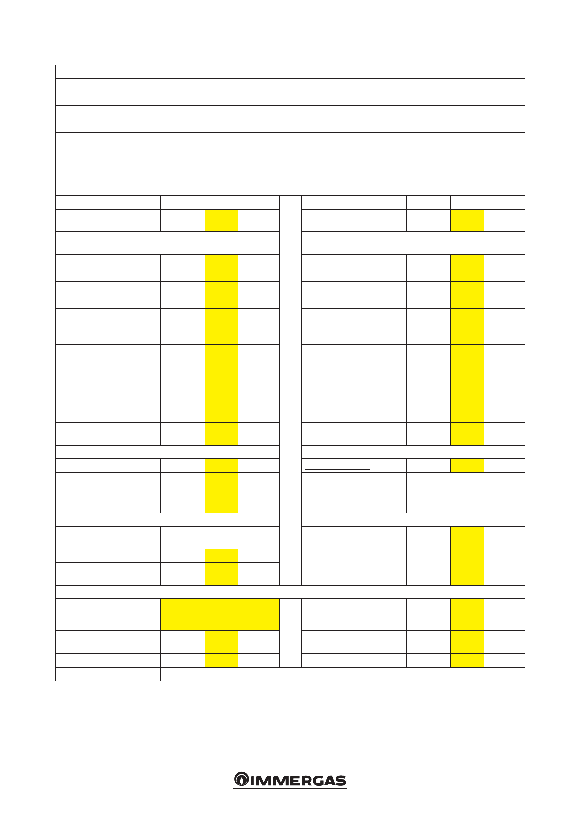
Average temperature table (47/55) colder zones
Model: Magis Pro 8 ErP
Air/water heat pump: yes
Water/water heat pump: no
Brine/water heat pump: no
Low temperature heat pump: no
With additional central heating device: no
Mixed central heating device with heat pump: no
e parameters are declared for average temperature application, except for low temperature heat pumps. e parameters for low temperature heat
pumps are declared for low temperature application
e parameters are declared for colder climatic conditions
Element Symbol Val ue Unit Element Symbol Val ue Unit
Nominal heat output
Nominal
output
11.10 kW
Central heating capacity declared with a partial load and indoor
temperature equivalent to 20°C and outdoor temperature Tj
Room central heating seasonal energy eciency
η
s
92 %
Performance coecient declared with indoor temperature equivalent
to 20°C and outdoor temperature TJ
Tj = –7°C Pdh 8.0 kW Tj = –7°C COPd 2.22 –
Tj = +2°C Pdh 6.4 kW Tj = +2°C COPd 3.03 –
Tj = +7°C Pdh 7.8 kW Tj = +7°C COPd 4.40 –
Tj = 12°C Pdh 9.5 kW Tj = 12°C COPd 5.53 –
Tj = bivalent temperature Pdh 6.7 kW Tj = bivalent temperature COPd 2.22 –
Tj = temperature operating
limit
Pdh 6.0 kW
for air/water heat pumps: Tj
= –15°C
Pdh kW
(if TOL < –20°C)
Bivalent temperature T
Central heating capacity cycle
intervals
-7 °C
biv
Pcych kW Cycle intervals eciency
Degradation coecient Cdh 1.0 —
Tj = temperature operating
limit
for air/water heat pumps: Tj
= –15°C
(if TOL < –20°C)
for air/water heat pumps: temperature operating limit
Water heating temperature
operating limit
COPd 1.75 –
COPd –
TOL -10 °C
COPcyc or
PERcyc
–
WTOL 55 °C
Dierent mode of energy consumption from the active mode Additional heating appliance
OFF mode P
OFF
0.000 kW Nominal heat output Psup 11.10 kW
ermostat mode o PTO 0.015 kW
Type of energy supply voltage electricalStandby mode P
Guard heating mode P
SB
CK
0.015 kW
0.015 kW
Other items
Capacity control Var iable
Indoor/outdoor sound level L
Annual energy consumption Q
WA
HE
N/A dB
11475
kWh or
GJ
For air/water heat pumps:
nominal air output to outside
For water or brine/water heat
pumps: nominal ow of brine or
water, outdoor heat exchanger
— m3/h
— m3/h
For mixed central heating appliances with a heat pump
Stated load prole
Daily electrical power consumption
Q
elec
kWh Daily fuel consumption Q
Water central heating energy
eciency
η
wh
fuel
%
kWh
annual energy consumption AEC kWh Annual fuel consumption AFC GJ
Contact information Immergas s.p.a via Cisa Ligure n.95
4343
Page 44

Average temperature table (47/55) average zones
Model: Magis Pro 8 ErP
Air/water heat pump: yes
Water/water heat pump: no
Brine/water heat pump: no
Low temperature heat pump: no
With additional central heating device: no
Mixed central heating device with heat pump: no
e parameters are declared for average temperature application, except for low temperature heat pumps. e parameters for low temperature heat
pumps are declared for low temperature application
e parameters are declared for average climatic conditions
Element Symbol Val ue Unit Element Symbol Val ue Unit
Nominal heat output
Nominal
output
7.00 kW
Central heating capacity declared with a partial load and indoor
temperature equivalent to 20°C and outdoor temperature Tj
Room central heating seasonal energy eciency
η
s
103 %
Performance coecient declared with indoor temperature equivalent
to 20°C and outdoor temperature TJ
Tj = –7°C Pdh 4.7 kW Tj = –7°C COPd 1.41 –
Tj = +2°C Pdh 6.2 kW Tj = +2°C COPd 2.67 –
Tj = +7°C Pdh 7.7 kW Tj = +7°C COPd 3.86 –
Tj = 12°C Pdh 8.9 kW Tj = 12°C COPd 4.90 –
Tj = bivalent temperature Pdh 5.3 kW Tj = bivalent temperature COPd 1.91 –
Tj = temperature operating
limit
Pdh 4.0 kW
for air/water heat pumps: Tj
= –15°C
Pdh kW
(if TOL < –20°C)
Bivalent temperature T
Central heating capacity cycle
intervals
-4 °C
biv
Pcych kW Cycle intervals eciency
Degradation coecient Cdh 1.0 –
Tj = temperature operating
limit
for air/water heat pumps: Tj
= –15°C
(if TOL < –20°C)
for air/water heat pumps: temperature operating limit
Water heating temperature
operating limit
COPd 0.98 –
COPd –
TOL -10 °C
COPcyc or
PERcyc
–
WTOL 55 °C
Dierent mode of energy consumption from the active mode Additional heating appliance
OFF mode P
OFF
0.000 kW Nominal heat output Psup 3.00 kW
ermostat mode o PTO 0.015 kW
Type of energy supply voltage electricalStandby mode P
Guard heating mode P
SB
CK
0.015 kW
0.015 kW
Other items
Capacity control Var iable
Indoor/outdoor sound level L
Annual energy consumption Q
WA
HE
N/A dB
5469
kWh or
GJ
For air/water heat pumps:
nominal air output to outside
For water or brine/water heat
pumps: nominal ow of brine or
water, outdoor heat exchanger
— m3/h
— m3/h
For mixed central heating appliances with a heat pump
Stated load prole
Daily electrical power consumption
Q
elec
kWh Daily fuel consumption Q
Water central heating energy
eciency
η
wh
fuel
%
kWh
annual energy consumption AEC kWh Annual fuel consumption AFC GJ
Contact information Immergas s.p.a via Cisa Ligure n.95
4444
Page 45

Average temperature table (47/55) hotter zones
Model: Magis Pro 8 ErP
Air/water heat pump: yes
Water/water heat pump: no
Brine/water heat pump: no
Low temperature heat pump: no
With additional central heating device: no
Mixed central heating device with heat pump: no
e parameters are declared for average temperature application, except for low temperature heat pumps. e parameters for low temperature heat
pumps are declared for low temperature application
e parameters are declared for hotter climatic conditions
Element Symbol Val ue Unit Element Symbol Val ue Unit
Nominal heat output
Nominal
output
6.90 kW
Central heating capacity declared with a partial load and indoor
temperature equivalent to 20°C and outdoor temperature Tj
Room central heating seasonal energy eciency
η
s
114 %
Performance coecient declared with indoor temperature equivalent
to 20°C and outdoor temperature TJ
Tj = –7°C Pdh - kW Tj = –7°C COPd - –
Tj = +2°C Pdh 4.9 kW Tj = +2°C COPd 1.54 –
Tj = +7°C Pdh 7.2 kW Tj = +7°C COPd 2.57 –
Tj = 12°C Pdh 8.7 kW Tj = 12°C COPd 4.66 –
Tj = bivalent temperature Pdh 5.8 kW Tj = bivalent temperature COPd 2.40 –
Tj = temperature operating
limit
Pdh 4.9 kW
for air/water heat pumps: Tj
= –15°C
Pdh kW
(if TOL < –20°C)
Bivalent temperature T
Central heating capacity cycle
intervals
4 °C
biv
Pcych kW Cycle intervals eciency
Degradation coecient Cdh 1.0 —
Tj = temperature operating
limit
for air/water heat pumps: Tj
= –15°C
(if TOL < –20°C)
for air/water heat pumps: temperature operating limit
Water heating temperature
operating limit
COPd 1.54 –
COPd –
TOL 2 °C
COPcyc or
PERcyc
–
WTOL 55 °C
Dierent mode of energy consumption from the active mode Additional heating appliance
OFF mode P
OFF
0.000 kW Nominal heat output Psup 2.00 kW
ermostat mode o PTO 0.015 kW
Type of energy supply voltage electricalStandby mode P
Guard heating mode P
SB
CK
0.015 kW
0.015 kW
Other items
Capacity control Var iable
Indoor/outdoor sound level L
Annual energy consumption Q
WA
HE
N/A dB
2882
kWh or
GJ
For air/water heat pumps:
nominal air output to outside
For water or brine/water heat
pumps: nominal ow of brine or
water, outdoor heat exchanger
— m3/h
— m3/h
For mixed central heating appliances with a heat pump
Stated load prole
Daily electrical power consumption
Q
elec
kWh Daily fuel consumption Q
Water central heating energy
eciency
η
wh
fuel
%
kWh
annual energy consumption AEC kWh Annual fuel consumption AFC GJ
Contact information Immergas s.p.a via Cisa Ligure n.95
4545
Page 46
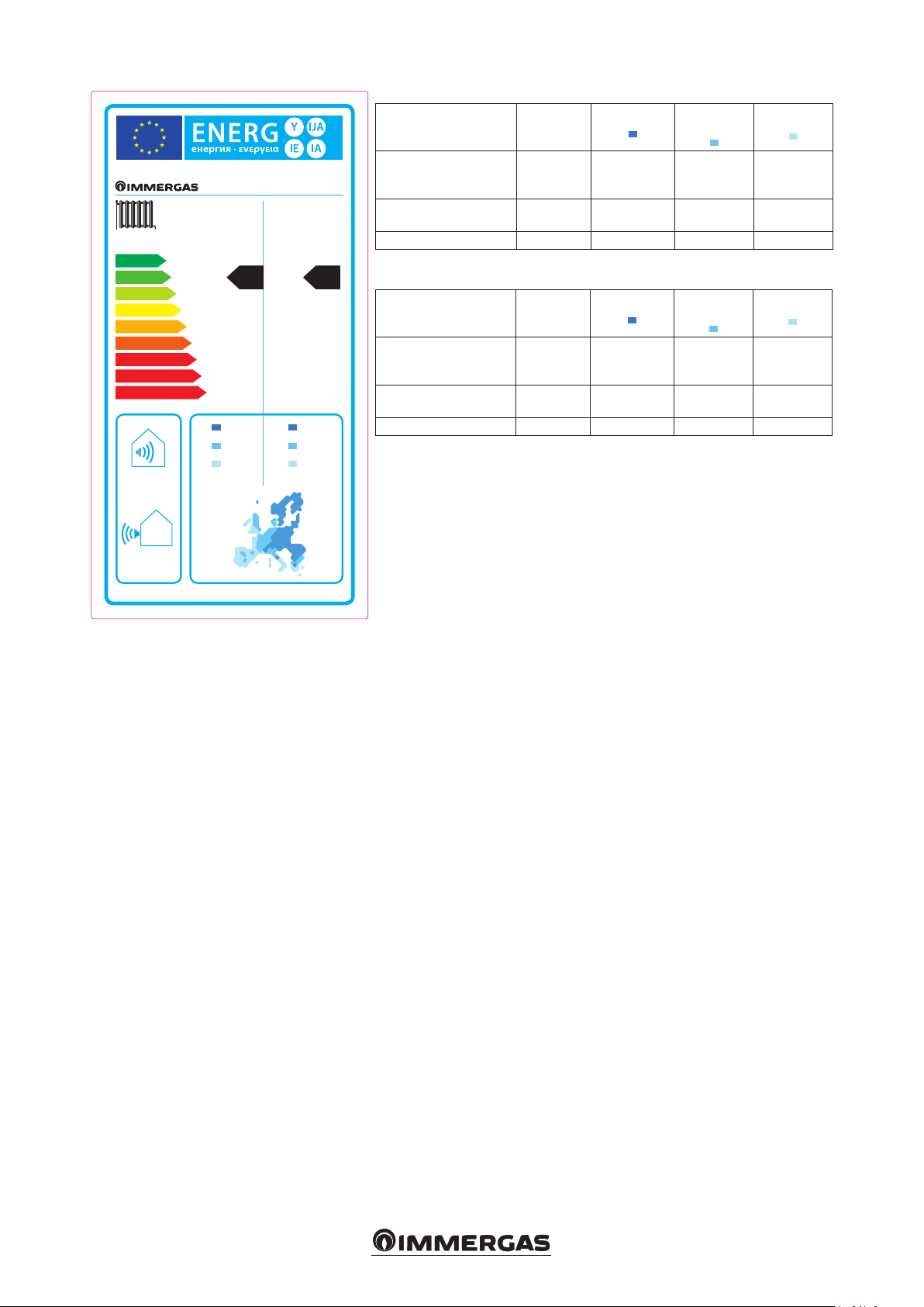
D
E
F
G
Low temperature (30/35)
Parameter Val ue
Annual energy consumption for the heating
MAGIS PRO 10 ERP
55 °C 35 °C
++
A
A
+
A
B
A
C
B
C
D
E
F
G
+
A
12,30 9,00
function (QHE)
Room central heating
seasonal eciency (ηs)
Nominal heat output kW 9.00 10.00 8.80
+
A
Average temperature (47/55)
Parameter Val ue
Annual energy consumption for the heating
function (QHE)
Room central heating
seasonal eciency (ηs)
Nominal heat output kW 12.30 9.30 9.0
kWh/year 6980 5569 2376
ηs % 124 145 194
kWh/year 13274 7214 3765
ηs % 88 104 124
Colder zones
Colder zones
Average
zones
Average
zones
Hotter zones
Hotter zones
9,30 10,00
For proper installation of the appliance refer to chapter 1 of this booklet (for the installer)
and current installation regulations. For proper maintenance refer to chapter 3 of this booklet
(for the maintenance technician) and adhere to the frequencies and methods set out herein.
dB
9,0 8,80
kW kW
66
dB
46
46
Page 47

Low temperature table (30/35) colder zones
Model: Magis Pro 10 ErP
Air/water heat pump: yes
Water/water heat pump: no
Brine/water heat pump: no
Low temperature heat pump: yes
With additional central heating device: no
Mixed central heating device with heat pump: no
e parameters are declared for average temperature application, except for low temperature heat pumps. e parameters for low temperature heat
pumps are declared for low temperature application
e parameters are declared for colder climatic conditions.
Element Symbol Val ue Unit Element Symbol Val ue Unit
Nominal heat output
Nominal
output
9.00 kW
Central heating capacity declared with a partial load and indoor
temperature equivalent to 20°C and outdoor temperature Tj
Room central heating seasonal energy eciency
η
s
124 %
Performance coecient declared with indoor temperature equivalent
to 20°C and outdoor temperature TJ
Tj = –7°C Pdh 8.9 kW Tj = –7°C COPd 2.67 –
Tj = +2°C Pdh 8.3 kW Tj = +2°C COPd 3.72 –
Tj = +7°C Pdh 10.3 kW Tj = +7°C COPd 5.68 –
Tj = 12°C Pdh 12.4 kW Tj = 12°C COPd 6.07 –
Tj = bivalent temperature Pdh 6.9 kW Tj = bivalent temperature COPd 2.25 –
Tj = temperature operating
limit
Pdh 6.6 kW
for air/water heat pumps: Tj
= –15°C
Pdh kW
(if TOL < –20°C)
Bivalent temperature T
Central heating capacity cycle
intervals
-15 °C
biv
Pcych kW Cycle intervals eciency
Degradation coecient Cdh 1.0 —
Tj = temperature operating
limit
for air/water heat pumps: Tj
= –15°C
(if TOL < –20°C)
for air/water heat pumps: temperature operating limit
Water heating temperature
operating limit
COPd 1.93 –
COPd –
TOL -20 °C
COPcyc or
PERcyc
–
WTOL 55 °C
Dierent mode of energy consumption from the active mode Additional heating appliance
OFF mode P
OFF
0.000 kW Nominal heat output Psup 13.10 kW
ermostat mode o PTO 0.015 kW
Type of energy supply voltage electricalStandby mode P
Guard heating mode P
SB
CK
0.015 kW
0.015 kW
Other items
Capacity control Va r iable
Indoor/outdoor sound level L
Annual energy consumption Q
WA
HE
N/A dB
kWh or
6980
GJ
For air/water heat pumps:
nominal air output to outside
For water or brine/water heat
pumps: nominal ow of brine or
water, outdoor heat exchanger
— m3/h
— m3/h
For mixed central heating appliances with a heat pump
Stated load prole
Daily electrical power consumption
Q
elec
kWh Daily fuel consumption Q
Water central heating energy
eciency
η
wh
fuel
%
kWh
annual energy consumption AEC kWh Annual fuel consumption AFC GJ
Contact information Immergas s.p.a via Cisa Ligure n.95
4747
Page 48

Low temperature table (30/35) average zones
Model: Magis Pro 10 ErP
Air/water heat pump: yes
Water/water heat pump: no
Brine/water heat pump: no
Low temperature heat pump: yes
With additional central heating device: no
Mixed central heating device with heat pump: no
e parameters are declared for average temperature application, except for low temperature heat pumps. e parameters for low temperature heat
pumps are declared for low temperature application
e parameters are declared for average climatic conditions.
Element Symbol Val ue Unit Element Symbol Val ue Unit
Nominal heat output
Nominal
output
10.00 kW
Central heating capacity declared with a partial load and indoor
temperature equivalent to 20°C and outdoor temperature Tj
Room central heating seasonal energy eciency
η
s
145 %
Performance coecient declared with indoor temperature equivalent
to 20°C and outdoor temperature TJ
Tj = –7°C Pdh 8.7 kW Tj = –7°C COPd 2.53 –
Tj = +2°C Pdh 8.3 kW Tj = +2°C COPd 3.53 –
Tj = +7°C Pdh 10.2 kW Tj = +7°C COPd 5.27 –
Tj = 12°C Pdh 12.4 kW Tj = 12°C COPd 5.85 –
Tj = bivalent temperature Pdh 8.4 kW Tj = bivalent temperature COPd 2.53 –
Tj = temperature operating
limit
Pdh 8.1 kW
for air/water heat pumps: Tj
= –15°C
Pdh kW
(if TOL < –20°C)
Bivalent temperature T
Central heating capacity cycle
intervals
-6 °C
biv
Pcych kW Cycle intervals eciency
Degradation coecient Cdh 1.0 —
Tj = temperature operating
limit
for air/water heat pumps: Tj
= –15°C
(if TOL < –20°C)
for air/water heat pumps: temperature operating limit
Water heating temperature
operating limit
COPd 2.59 –
COPd –
TOL -10 °C
COPcyc or
PERcyc
–
WTOL 55 °C
Dierent mode of energy consumption from the active mode Additional heating appliance
OFF mode P
OFF
0.000 kW Nominal heat output Psup 1.90 kW
ermostat mode o PTO 0.015 kW
Type of energy supply voltage electricalStandby mode P
Guard heating mode P
SB
CK
0.015 kW
0.015 kW
Other items
Capacity control Va r iable
Indoor/outdoor sound level L
Annual energy consumption Q
WA
HE
66 dB
5569
kWh or
GJ
For air/water heat pumps:
nominal air output to outside
For water or brine/water heat
pumps: nominal ow of brine or
water, outdoor heat exchanger
— m3/h
— m3/h
For mixed central heating appliances with a heat pump
Stated load prole
Daily electrical power consumption
Q
elec
kWh Daily fuel consumption Q
Water central heating energy
eciency
η
wh
fuel
%
kWh
annual energy consumption AEC kWh Annual fuel consumption AFC GJ
Contact information Immergas s.p.a via Cisa Ligure n.95
4848
Page 49

Low temperature table (30/35) hotter zones
Model: Magis Pro 10 ErP
Air/water heat pump: yes
Water/water heat pump: no
Brine/water heat pump: no
Low temperature heat pump: yes
With additional central heating device: no
Mixed central heating device with heat pump: no
e parameters are declared for average temperature application, except for low temperature heat pumps. e parameters for low temperature heat
pumps are declared for low temperature application
e parameters are declared for hotter climatic conditions.
Element Symbol Val ue Unit Element Symbol Val ue Unit
Nominal heat output
Nominal
output
8.80 kW
Central heating capacity declared with a partial load and indoor
temperature equivalent to 20°C and outdoor temperature Tj
Room central heating seasonal energy eciency
η
s
194 %
Performance coecient declared with indoor temperature equivalent
to 20°C and outdoor temperature TJ
Tj = –7°C Pdh - kW Tj = –7°C COPd - –
Tj = +2°C Pdh 8.4 kW Tj = +2°C COPd 3.01 –
Tj = +7°C Pdh 10.0 kW Tj = +7°C COPd 4.73 –
Tj = 12°C Pdh 12.3 kW Tj = 12°C COPd 5.85 –
Tj = bivalent temperature Pdh 10.6 kW Tj = bivalent temperature COPd 4.08 –
Tj = temperature operating
limit
Pdh 8.4 kW
for air/water heat pumps: Tj
= –15°C
Pdh kW
(if TOL < –20°C)
Bivalent temperature T
Central heating capacity cycle
intervals
7 °C
biv
Pcych kW Cycle intervals eciency
Degradation coecient Cdh 1.0 —
Tj = temperature operating
limit
for air/water heat pumps: Tj
= –15°C
(if TOL < –20°C)
for air/water heat pumps: temperature operating limit
Water heating temperature
operating limit
COPd 3.01 –
COPd –
TOL 2 °C
COPcyc or
PERcyc
–
WTOL 55 °C
Dierent mode of energy consumption from the active mode Additional heating appliance
OFF mode P
OFF
0.000 kW Nominal heat output Psup 0.42 kW
ermostat mode o PTO 0.015 kW
Type of energy supply voltage electricalStandby mode P
Guard heating mode P
SB
CK
0.015 kW
0.015 kW
Other items
Capacity control Va r iable
Indoor/outdoor sound level L
Annual energy consumption Q
WA
HE
N/A dB
kWh or
2376
GJ
For air/water heat pumps:
nominal air output to outside
For water or brine/water heat
pumps: nominal ow of brine or
water, outdoor heat exchanger
— m3/h
— m3/h
For mixed central heating appliances with a heat pump
Stated load prole
Daily electrical power consumption
Q
elec
kWh Daily fuel consumption Q
Water central heating energy
eciency
η
wh
fuel
%
kWh
annual energy consumption AEC kWh Annual fuel consumption AFC GJ
Contact information Immergas s.p.a via Cisa Ligure n.95
4949
Page 50

Average temperature table (47/55) colder zones
Model: Magis Pro 10 ErP
Air/water heat pump: yes
Water/water heat pump: no
Brine/water heat pump: no
Low temperature heat pump: no
With additional central heating device: no
Mixed central heating device with heat pump: no
e parameters are declared for average temperature application, except for low temperature heat pumps. e parameters for low temperature heat
pumps are declared for low temperature application
e parameters are declared for colder climatic conditions
Element Symbol Val ue Unit Element Symbol Val ue Unit
Nominal heat output
Nominal
output
12.30 kW
Central heating capacity declared with a partial load and indoor
temperature equivalent to 20°C and outdoor temperature Tj
Room central heating seasonal energy eciency
η
s
88 %
Performance coecient declared with indoor temperature equivalent
to 20°C and outdoor temperature TJ
Tj = –7°C Pdh 8.1 kW Tj = –7°C COPd 2.05 –
Tj = +2°C Pdh 8.4 kW Tj = +2°C COPd 2.97 –
Tj = +7°C Pdh 10.0 kW Tj = +7°C COPd 4.36 –
Tj = 12°C Pdh 12.0 kW Tj = 12°C COPd 5.54 –
Tj = bivalent temperature Pdh 8.1 kW Tj = bivalent temperature COPd 2.05 –
Tj = temperature operating
limit
Pdh 6.9 kW
for air/water heat pumps: Tj
= –15°C
Pdh kW
(if TOL < –20°C)
Bivalent temperature T
Central heating capacity cycle
intervals
-7 °C
biv
Pcych kW Cycle intervals eciency
Degradation coecient Cdh 1.0 —
Tj = temperature operating
limit
for air/water heat pumps: Tj
= –15°C
(if TOL < –20°C)
for air/water heat pumps: temperature operating limit
Water heating temperature
operating limit
COPd 1.75 –
COPd –
TOL -10 °C
COPcyc or
PERcyc
–
WTOL 55 °C
Dierent mode of energy consumption from the active mode Additional heating appliance
OFF mode P
OFF
0.000 kW Nominal heat output Psup 12.30 kW
ermostat mode o PTO 0.015 kW
Type of energy supply voltage electricalStandby mode P
Guard heating mode P
SB
CK
0.015 kW
0.015 kW
Other items
Capacity control Va r iable
Indoor/outdoor sound level L
Annual energy consumption Q
WA
HE
N/A dB
13274
kWh or
GJ
For air/water heat pumps:
nominal air output to outside
For water or brine/water heat
pumps: nominal ow of brine or
water, outdoor heat exchanger
— m3/h
— m3/h
For mixed central heating appliances with a heat pump
Stated load prole
Daily electrical power consumption
Q
elec
kWh Daily fuel consumption Q
Water central heating energy
eciency
η
wh
fuel
%
kWh
annual energy consumption AEC kWh Annual fuel consumption AFC GJ
Contact information Immergas s.p.a via Cisa Ligure n.95
5050
Page 51

Average temperature table (47/55) average zones
Model: Magis Pro 10 ErP
Air/water heat pump: yes
Water/water heat pump: no
Brine/water heat pump: no
Low temperature heat pump: no
With additional central heating device: no
Mixed central heating device with heat pump: no
e parameters are declared for average temperature application, except for low temperature heat pumps. e parameters for low temperature heat
pumps are declared for low temperature application
e parameters are declared for average climatic conditions
Element Symbol Val ue Unit Element Symbol Val ue Unit
Nominal heat output
Nominal
output
9.30 kW
Central heating capacity declared with a partial load and indoor
temperature equivalent to 20°C and outdoor temperature Tj
Room central heating seasonal energy eciency
η
s
104 %
Performance coecient declared with indoor temperature equivalent
to 20°C and outdoor temperature TJ
Tj = –7°C Pdh 5.9 kW Tj = –7°C COPd 1.51 –
Tj = +2°C Pdh 8.4 kW Tj = +2°C COPd 2.61 –
Tj = +7°C Pdh 9.8 kW Tj = +7°C COPd 3.88 –
Tj = 12°C Pdh 11.8 kW Tj = 12°C COPd 5.03 –
Tj = bivalent temperature Pdh 6.8 kW Tj = bivalent temperature COPd 2.37 –
Tj = temperature operating
limit
Pdh 4.5 kW
for air/water heat pumps: Tj
= –15°C
Pdh kW
(if TOL < –20°C)
Bivalent temperature T
Central heating capacity cycle
intervals
-3 °C
biv
Pcych kW Cycle intervals eciency
Degradation coecient Cdh 1.0 –
Tj = temperature operating
limit
for air/water heat pumps: Tj
= –15°C
(if TOL < –20°C)
for air/water heat pumps: temperature operating limit
Water heating temperature
operating limit
COPd 0.98 –
COPd –
TOL -10 °C
COPcyc or
PERcyc
–
WTOL 55 °C
Dierent mode of energy consumption from the active mode Additional heating appliance
OFF mode P
OFF
0.000 kW Nominal heat output Psup 4.80 kW
ermostat mode o PTO 0.015 kW
Type of energy supply voltage electricalStandby mode P
Guard heating mode P
SB
CK
0.015 kW
0.015 kW
Other items
Capacity control Va r iable
Indoor/outdoor sound level L
Annual energy consumption Q
WA
HE
N/A dB
kWh or
7214
GJ
For air/water heat pumps:
nominal air output to outside
For water or brine/water heat
pumps: nominal ow of brine or
water, outdoor heat exchanger
— m3/h
— m3/h
For mixed central heating appliances with a heat pump
Stated load prole
Daily electrical power consumption
Q
elec
kWh Daily fuel consumption Q
Water central heating energy
eciency
η
wh
fuel
%
kWh
annual energy consumption AEC kWh Annual fuel consumption AFC GJ
Contact information Immergas s.p.a via Cisa Ligure n.95
5151
Page 52

Average temperature table (47/55) hotter zones
Model: Magis Pro 10 ErP
Air/water heat pump: yes
Water/water heat pump: no
Brine/water heat pump: no
Low temperature heat pump: no
With additional central heating device: no
Mixed central heating device with heat pump: no
e parameters are declared for average temperature application, except for low temperature heat pumps. e parameters for low temperature heat
pumps are declared for low temperature application
e parameters are declared for hotter climatic conditions
Element Symbol Val ue Unit Element Symbol Val ue Unit
Nominal heat output
Nominal
output
9.0 kW
Central heating capacity declared with a partial load and indoor
temperature equivalent to 20°C and outdoor temperature Tj
Room central heating seasonal energy eciency
η
s
124 %
Performance coecient declared with indoor temperature equivalent
to 20°C and outdoor temperature TJ
Tj = –7°C Pdh - kW Tj = –7°C COPd - –
Tj = +2°C Pdh 6.6 kW Tj = +2°C COPd 1.54 –
Tj = +7°C Pdh 9.2 kW Tj = +7°C COPd 2.79 –
Tj = 12°C Pdh 11.3 kW Tj = 12°C COPd 4.26 –
Tj = bivalent temperature Pdh 7.6 kW Tj = bivalent temperature COPd 2.55 –
Tj = temperature operating
limit
Pdh 6.6 kW
for air/water heat pumps: Tj
= –15°C
Pdh kW
(if TOL < –20°C)
Bivalent temperature T
Central heating capacity cycle
intervals
4 °C
biv
Pcych kW Cycle intervals eciency
Degradation coecient Cdh 1.0 –
Tj = temperature operating
limit
for air/water heat pumps: Tj
= –15°C
(if TOL < –20°C)
for air/water heat pumps: temperature operating limit
Water heating temperature
operating limit
COPd 1.54 –
COPd –
TOL 2 °C
COPcyc or
PERcyc
–
WTOL 55 °C
Dierent mode of energy consumption from the active mode Additional heating appliance
OFF mode P
OFF
0.000 kW Nominal heat output Psup 2.44 kW
ermostat mode o PTO 0.015 kW
Type of energy supply voltage electricalStandby mode P
Guard heating mode P
SB
CK
0.015 kW
0.015 kW
Other items
Capacity control Va r iable
Indoor/outdoor sound level L
Annual energy consumption Q
WA
HE
N/A dB
kWh or
3765
GJ
For air/water heat pumps:
nominal air output to outside
For water or brine/water heat
pumps: nominal ow of brine or
water, outdoor heat exchanger
— m3/h
— m3/h
For mixed central heating appliances with a heat pump
Stated load prole
Daily electrical power consumption
Q
elec
kWh Daily fuel consumption Q
Water central heating energy
eciency
η
wh
fuel
%
kWh
annual energy consumption AEC kWh Annual fuel consumption AFC GJ
Contact information Immergas s.p.a via Cisa Ligure n.95
5252
Page 53
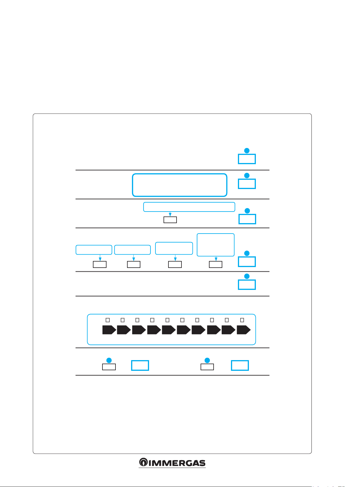
3.18 PARAMETERS FOR FILLING IN
THE PACKAGE FICHE.
Should you wish to install an assembly starting
from the Magis Pro ErP package, use the package
che shown in Fig. 3-11.
To ll it in correctly, enter the gures shown in
tables Fig. 3-9 and 3-10 (as shown in the package
che facsimile Fig. 3-8).
e remaining values must be obtained from
Facsimile for lling in the package che for preferential boiler space heaters.
Room central heating seasonal energy efciency of the heat pump
the technical data sheets of the products used to
make up the assembly (e.g. solar devices, integration boiler, temperature controllers).
Use sheet g. 3-11 for “assemblies” related to
the central heating function (e.g.: heat pump +
temperature controller).
N.B.: since the product is standard supplied with
a temperature controller, the package che must
always be completed.
1
‘I’
%
Temperature control
From temperature
control board
Supplementary boiler
From boiler board
Solar contribution
From the board of the solar device
Dimensions of the
manifold (in m2)
( ‘III’ x + ‘IV’ x ) x 0.45 x ( / 100) x =
Room central heating seasonal energy efciency of the assemble in average climate conditions
Room central heating seasonal energy efciency class of the assemble in average
climate conditions
G F E D C B A A
< 30 % ≥ 30 % ≥ 34 % ≥ 36 % ≥ 75 % ≥ 82 % ≥ 90 % ≥ 98 % ≥ 125 %≥ 150 %
Class I = 1 %, Class II = 2 %,
Class III = 1.5 %, Class IV = 2 %,
Class V = 3 %, Class VI = 4 %,
Class VII = 3.5 %, Class VIII = 5 %
Seasonal central heating energy efciency of the room
( - ‘I’ ) x “II” =
Volume of the
tank (in m3)
Efciency of the
manifold (in %)
(%)
Classication of the
tank
A* = 0.95, A = 0.91,
B = 0.86, C = 0.83,
D-G = 0.81
+
-
+
++
+
A
A
2
%
3
%
4
%
5
%
+++
Room central heating seasonal energy efciency in colder and hotter climate conditions
5 5
Colder: - ‘V’ = Hotter: + ‘VI’ =
The energy efciency of the set of products indicated in this sheet may not reect the actual
energy efciency after installation since such efciency is affected by additional factors, such as
the heat loss in the distribution system and the size of the products compared to the size and
features of the building.
% %
5353
Fig. 3-8
Page 54

Parameters to ll in the low temperature package che (30/35).
Magis Pro 5 ErP
Parameter
‘I’ 162 154 201
‘II’ * * *
‘III’ 3.43 4.86 4.45
‘IV’ 1.34 1.90 1.74
Parameter
‘I’ 124 145 194
‘II’ * * *
‘III’ 2.97 2.67 3.04
‘IV’ 1.16 1.04 1.19
* to be established by means of table 6 of Regulation 811/2013 in case of an “assembly” including a boiler to integrate with the heat pump. In this case, the
heat pump must be considered as the main appliance of the assembly.
Parameter Audax TOP
‘VI’ Remote control class supplied by default
Parameters to ll in the average temperature package che (47/55).
Parameter
Colder zones Average zones Hotter zones
Magis Pro 10 ErP
Colder zones Average zones Hotter zones
Magis Pro 5 ErP
Colder zones Average zones Hotter zones
Parameter
‘I’ 125 151 201
‘II’ * * *
‘III’ 5.24 4.86 4.69
‘IV’ 2.05 1.90 1.83
Parameter
Colder zones Average zones Hotter zones
Colder zones Average zones Hotter zones
Magis Pro 8 ErP
Fig. 3-9
Magis Pro 8 ErP
‘I’ 91 112 132
‘II’ * * *
‘III’ 3.47 4.31 4.95
‘IV’ 1.36 1.69 1.94
Magis Pro 10 ErP
Parameter
‘I’ 88 104 124
‘II’ * * *
‘III’ 2.17 2.87 2.97
‘IV’ 0.85 1.12 1.16
* to be established by means of table 6 of Regulation 811/2013 in case of an “assembly” including a boiler to integrate with the heat pump. In this case, the
heat pump must be considered as the main appliance of the assembly.
Parameter Audax TOP
‘VI’ Remote control class supplied by default
Colder zones Average zones Hotter zones
‘I’ 92 103 114
‘II’ * * *
‘III’ 2.41 3.82 3.87
‘IV’ 0.94 1.49 1.51
Fig. 3-10
5454
Page 55

Room central heating system package che.
Room central heating seasonal energy efciency of the heat pump
1
____
%
Temperature control
From temperature
control board
Supplementary boiler
From boiler board
Solar contribution
From the board of the solar device
Dimensions of the
manifold (in m2)
( ___ x + ____ x ) x 0.45 x ( / 100) x =
Room central heating seasonal energy efciency of the assemble in average climate conditions
Room central heating seasonal energy efciency class of the assemble in average
climate conditions
G F E D C B A A
< 30 % ≥ 30 % ≥ 34 % ≥ 36 % ≥ 75 % ≥ 82 % ≥ 90 % ≥ 98 % ≥ 125 %≥ 150 %
Class I = 1 %, Class II = 2 %,
Class III = 1.5 %, Class IV = 2 %,
Class V = 3 %, Class VI = 4 %,
Class VII = 3.5 %, Class VIII = 5 %
Seasonal central heating energy efciency of the room
( - ______ ) x _____ =
Volume of the
tank (in m3)
Efciency of the
manifold (in %)
(%)
Classication of the
tank
A* = 0.95, A = 0.91,
B = 0.86, C = 0.83,
D-G = 0.81
+
-
+
++
+
A
A
2
%
3
%
4
%
5
%
+++
Room central heating seasonal energy efciency in colder and hotter climate conditions
5 5
Colder: - __ = Warmer: + ___ =
The energy efciency of the set of products indicated in this sheet may not reect the actual
energy efciency after installation since such efciency is affected by additional factors, such as
the heat loss in the distribution system and the size of the products compared to the size and
features of the building.
% %
5555
Fig. 3-11
Page 56

Follow us
Immergas Italia
immergas.com
Immergas S.p.A.
42041 Brescello (RE) - Italy
Tel. 0522.689011
Fax 0522.680617
Certied company ISO 9001
is instruction booklet is made of ecological paper Cod. 1.039356ENG - rev. ST.002317/000 - 01/16 - Inglese per IRLANDA (IE)
 Loading...