

Page 1
Instructions and
recommendations
Installer
User
Maintenance technician
IE
JULIUS ECO 11-14
Wall-hung instantaneous water
heater open chamber (type B) and
natural draught
*1.042033ENG*
*1.042033ENG*
Page 2

Page 3

Dear Customer,
Congratulations for having chosen a top-quality Immergas product, able to assure well-being and safety for a long period of time. As an Immergas Customer,
you can also count on a qualied aer-sales service, prepared and updated to guarantee constant eciency of your water heater. Read the following pages
carefully: you will be able to draw useful tips on the proper use of the device, compliance with which will conrm your satisfaction with the Immergas product.
For assistance and scheduled maintenance contact Authorised Aer-Sales centres: they have original spare parts and are specically trained directly by the
manufacturer.
General warnings
All Immergas products are protected with suitable transport packaging.
e material must be stored in a dry place protected from the weather.
e instruction booklet is an integral and essential part of the product and must be given to the new user in the case of transfer or succession of ownership.
It must be stored with care and consulted carefully, as all of the warnings provide important safety indications for installation, use and maintenance stages.
is instructions manual provides technical information for installing Immergas water heaters. As for the other issues related to water heater installation (e.g.
safety in the work site, environment protection, injury prevention), it is necessary to comply with the provisions of the regulations in force and the principles
of good practice.
Installation and maintenance must be performed in compliance with the regulations in force, according to the manufacturer's instructions and by an authorised
company, which has the specic technical skills in the system sector, as provided for by Law.
Improper installation or assembly of the Immergas appliance and/or components, accessories, kits and devices can cause unexpected problems for people,
animals and objects. Read the instructions provided with the product carefully to ensure proper installation.
Maintenance must be carried out by an authorised company. e Authorised Aer-sales Service represents a guarantee of qualication and professionalism.
e appliance must only be destined for the use for which it has been expressly declared. Any other use will be considered improper and therefore potentially
dangerous.
If errors occur during installation, operation and maintenance, due to non-compliance with technical laws in force, standards or instructions contained in
this book (or however supplied by the manufacturer), the manufacturer is excluded from any contractual and extra-contractual liability for any damage and
the appliance warranty is invalidated.
e company IMMERGAS S.p.A., with registered oce in via Cisa Ligure 95 42041 Brescello (RE), declares that the design, manufacturing and aer-sales
assistance processes comply with the requirements of standard UNI EN ISO 9001:2015.
For further details on the product CE marking, request a copy of the Declaration of Conformity from the manufacturer, specifying the appliance model
and the language of the country.
e manufacturer declines all liability due to printing or transcription errors, reserving the right to make any modications to its technical and commercial documents without forewarning.
Page 4

INDEX
1 Installation water heater. ..........................5
1.1 Installation recommendations. ................5
1.2 Main dimensions. ......................................6
1.3 Gas connection. ......................................... 6
1.4 Hydraulic connection. ..............................7
1.5 Electric power supply. ............................... 7
1.6 Ventilation of the rooms...........................7
1.7 Flue ducts. .................................................. 7
1.8 Flues/Chimneys. ........................................7
1.9 Gas system start-up. ..................................7
1.10 Appliance start-up (ignition). ................... 7
1.11 Kits available on request. .......................... 7
1.12 Water heater components. .......................8
USER page INSTALLER page MAINTENANCE TECHNICIAN page
2 Instructions for use and maintenance. ... 9
2.1 Cleaning and maintenance. .....................9
2.2 Ventilation of the rooms...........................9
2.3 General warnings. ..................................... 9
2.4 Control panel. ............................................9
2.5 Use of the water heater. ............................9
2.6 Description of the anomalies. ................10
2.7 Switch-o of the water heater. ...............11
2.8 Battery replacement. ...............................11
2.9 Emptying the water heater. .................... 11
2.10 Protection against freezing. ...................11
2.11 Cleaning the case. .................................... 11
2.12 Decommissioning. ..................................11
2.13 Gas system not used for periods
over 12 months. .......................................11
3 Control and maintenance. .....................12
3.1 Hydraulic Diagram. ................................12
3.2 Chimney safety thermostat reset. .........13
3.3 Wiring diagram. ......................................13
3.4 Possible problems and their causes. ......14
3.5 Converting the water heater to other
types of gas. .............................................. 14
3.6 Transformation from methane to LPG. 14
3.7 Transformation from LPG to methane. 15
3.8 Possible adjustments. ..............................15
3.9 Yearly appliance check and
maintenance. ............................................16
3.10 Casing removal. .......................................16
3.11 Combustion parameters. ........................16
3.12 Technical data. .........................................17
3.13 Product che (in compliance with
Regulation 812/2013). ............................18
Page 5
INSTALLATION
1
WATER HEATER.
1.1 INSTALLATION
RECOMMENDATIONS.
e Julius Eco 11-14 water heater has been designed for wall installation. It must be used for
the production of domestic hot water and similar
purposes. In the case of wall installation the wall
surface must be smooth, without any protrusions
or recesses enabling access to the rear part. ey
are not designed to be installed on plinths or
oors (Fig. 1-1).
e place of installation of the appliance and
relative Immergas accessories must have suitable
features (technical and structural), such as to allow for (always in safe, ecient and comfortable
conditions):
- installation (according to the provisions of
technical legislation and technical regulations);
- maintenance operations (including scheduled,
periodic, routine and special maintenance);
- removal (outdoors in the place for loading and
transporting the appliances and components)
as well as their eventual replacement with appliances and/or equivalent components.
Only professionally qualified companies are
authorised to install Immergas gas appliances.
Installation must be carried out according to
regulation standards, current legislation and in
compliance with local technical regulations and
the required technical procedures.
Attention: it is forbidden to install appliances
removed from other systems. e manufacturer
declines all liability in the event of damage caused
by water heaters removed from other systems or
for any non-conformities with such equipment.
Installation of the Julius Eco 11-14 water heater
when powered by LPG must comply with the
rules regarding gases with a greater density
than air (remember, as an example, that it is
prohibited to install systems powered with the
above-mentioned gas in rooms where the oor
is at a lower quota that the average external
country one).
Before installing the appliance, ensure it has been
delivered in perfect condition; if in doubt, contact
the supplier immediately. Packing materials (staples, nails, plastic bags, polystyrene foam, etc.)
constitute a hazard and must be kept out of the
reach of children.
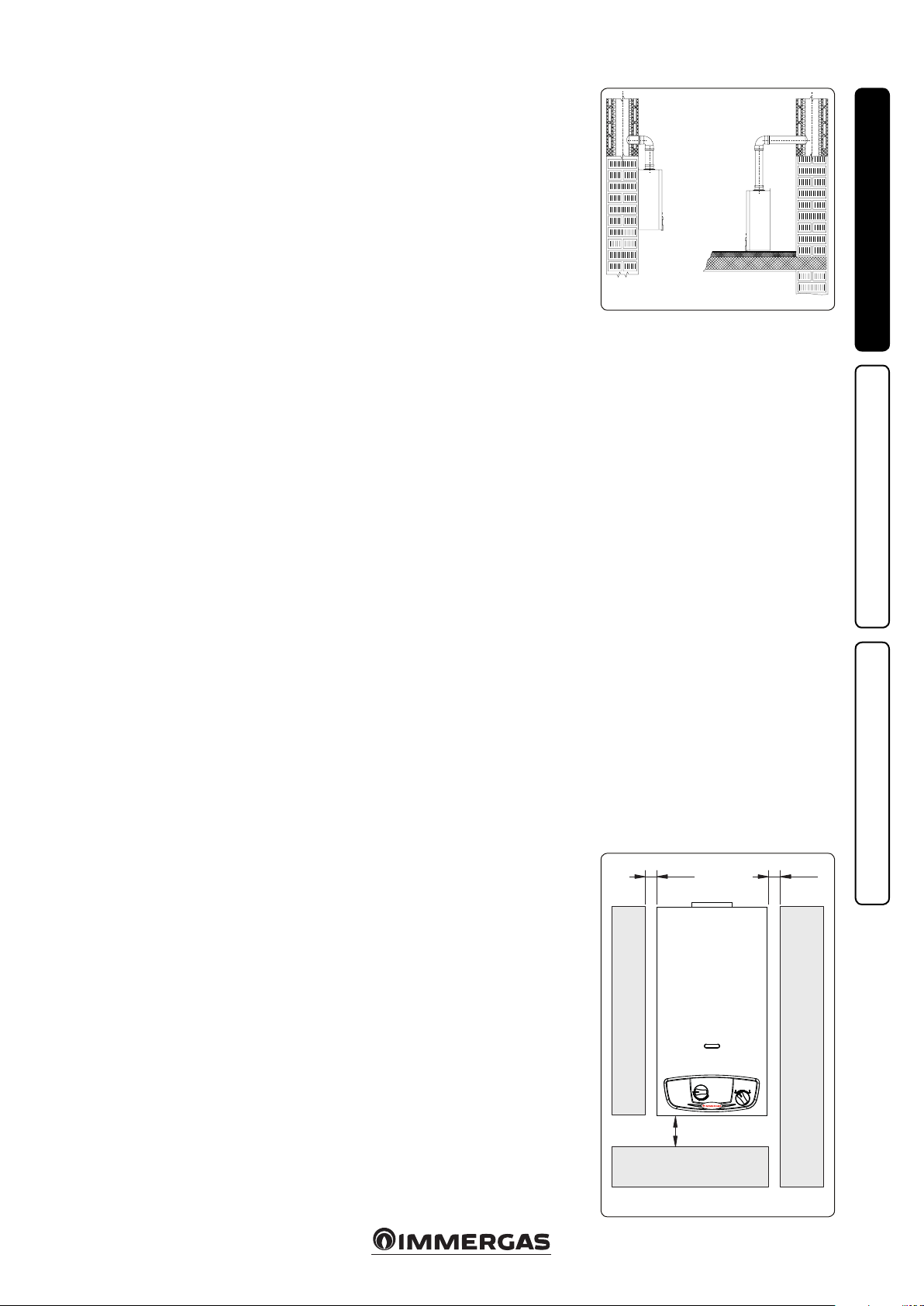
If the appliance is installed inside or between
cabinets, ensure sufficient space for normal
servicing; therefore it is advisable to leave clearance of at least 50 cm between the water heater
casing and the vertical sides of the cabinet (Ref.
Fig. 1-1A). Leave adequate space above the
water heater for possible water and ue removal
connections.
Do not rest objects on the appliance.
Keep all ammable objects away from the appliance (paper, rags, plastic, polystyrene, etc.).
It is recommended not to position household
appliances under the water heater because they
could undergo damage in the case of leaks from
the hydraulic ttings. If this is not the case, the
manufacturer cannot be considered liable for
any damage caused to the household appliances.
For the aforementioned reasons, we recommend
not placing furnishings, furniture, etc. under the
water heater.
In the event of malfunctions, faults or incorrect
operation, turn the appliance o and contact an
authorised company (e.g. the Authorised Technical Assistance centre, which has specically
trained sta and original spare parts). Do not
attempt to modify or repair the appliance alone.
Failure to comply with the above implies personal
responsibility and invalidates the warranty.
• Installation Standards:
- these water heaters cannot be installed in
bedrooms, studio ats and bathrooms. ey
also cannot be installed in rooms with wood
(or solid fuel) burning heat generators and in
communicating rooms.
- Installation in places with a re risk is prohibited (for example: underground car parks,
garages), potentially dangerous places, gas
appliances and relative ue ducts.
- Installation on the vertical projection of cooking hobs is forbidden.
- Installation is forbidden in places/rooms that
constitute public areas of apartment buildings, internal stairways or other escape routes
(e.g. oor landings, entrance halls, etc.).
- Installation is also forbidden in places/rooms
that constitute public areas of apartment
buildings such as cellars, entrance halls, attics, los, etc., unless otherwise provided for
by local regulations in force.
- It is forbidden to install the water heater
inside a closed recessed frame (e.g. Omni
Container).
- Type B open chamber water heaters must
not be installed in places where commercial,
artisan or industrial activities take place,
which use products that may develop volatile
vapours or substances (e.g. acid vapours,
glues, paints, solvents, combustibles, etc.),
as well as dusts (e.g. dust deriving from the
working of wood, coal nes, cement, etc.).
ese may be damaging for the components
of the appliance and jeopardise functioning.
- ey must also be installed in an environment in which the temperature cannot fall
below 0°C. They must not be exposed to
atmospheric agents.
YES NO
Attention: wall mounting of the water heater
must guarantee stable and ecient support for
the generator.
e dowels, which come as standard, can only
ensure adequate support if inserted correctly
(according to technical standards) in walls made
of solid or semi-hollow brick or block. In the
case of walls made from hollow brick or block,
partitions with limited static properties, or in any
case walls other than those indicated, a static test
must be carried out to ensure adequate mount.
ese appliances are used to heat water to below
boiling temperature in atmospheric pressure.
ey must be connected to a DHW distribution
network suited to their performance and power.
Minimum installation distances.
Fig. 1-1
50 50
INSTALLERUSER
MAINTENANCE TECHNICIAN
JULIUS ECO
200
Fig. 1-1A
5
Page 6
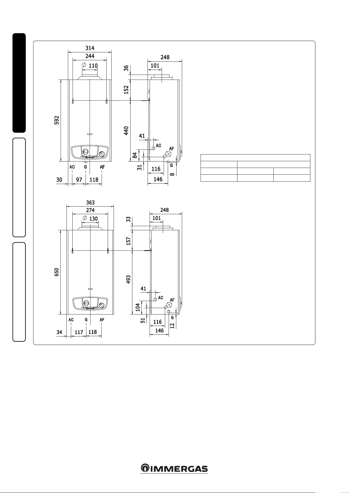
1.2 MAIN DIMENSIONS.
Julius Eco 11
INSTALLERUSER
CONNECTIONS
GAS DOMESTIC HOT WATER
G AC AF
* 1/2” 1/2” 1/2”
* Connection unit optional available with 3/4” cock
Julius Eco 14
MAINTENANCE TECHNICIAN
1.3 GAS CONNECTION.
Our water heaters are designed to operate with
methane gas (G20) and LPG. Supply pipes must
be the same as or larger than the 1/2”G water
heater tting. Before connecting the gas line,
carefully clean inside all the fuel feed system
pipes to remove any residue that could impair
water heater eciency. Also make sure the gas
corresponds to that for which the water heater
is prepared (see water heater data-plate). If different, the water heater must be converted for
operation with the other type of gas (see converting appliance for other gas types). It is also
important to check the dynamic pressure of the
mains (methane or LPG) used to supply the water
heater, which must comply with EN437 and its
attachment, as insucient levels may reduce generator output and cause discomfort to the user.
Key:
AC - Domestic hot water outlet
AF - Domestic cold water inlet
G - Gas supply
A type-approved and certied gas cut-o cock
must be inserted on the gas pipe before connection to the appliance.
Ensure correct gas cock connection, by inserting
a at gasket. e gas supply pipe must be suitably
dimensioned according to current regulations
in order to guarantee correct gas ow rate to the
burner even in conditions of maximum generator output and to guarantee appliance eciency
(technical specications). e coupling system
must conform to standards in force (EN 1775).
Fig. 1-2
Fuel gas quality. e appliance was designed
to operate with combustible gas free of impurities; otherwise it is advisable to t special lters
upstream of the appliance to restore the purity
of the fuel.
Storage tanks (in case of supply from LPG depot).
- New LPG storage tanks may contain residual inert
gases (nitrogen) that degrade the mixture delivered
to the appliance casing functioning anomalies.
- Due to the composition of the LPG mixture, layering of the mixture components may occur during
the period of storage in the tanks. is can cause
a variation in the caloric value of the mixture
delivered to the appliance, with subsequent change
in its performance.
6
Page 7

1.4 HYDRAULIC CONNECTION.
Attention: before connecting the water heater and
so as not to make the warranty null and void on the
DHW heat exchanger, wash the system thoroughly
(piping, etc.) in a way to remove any residue that
could compromise the good functioning of the
water heater. Hydraulic connections must be made
in a rational way following the set-up of the water
heater couplings.
Attention: to preserve the duration of appliance
eciency features, in the presence of water whose
features can lead to the deposit of lime scale, installation of the polyphosphate dispenser is recommended.
1.5 ELECTRIC POWER SUPPLY.
is water heater is powered by direct current via
one 1.5 V “LR 20” alkaline battery.
N.B.: The appliance is supplied by Immergas
with a battery in the packaging box and then not
connected.
In the ignition phase, it is therefore necessary to
connect it, setting it up in the correct position.
e battery is housed in a relevant compartment
organised in the lower le area, near to the hydraulic
couplings (Fig. 1-3).
Attention: water heater pipes must never be used
to earth the electric or telephone lines. Ensure that
this does not occur before the battery is inserted.
1.6 VENTILATION OF THE ROOMS.
In the room in which the water heater is installed
it is necessary that at least as much air ows as
that requested for by normal combustion of the
gas and ventilation of the room. Natural air ow
must take place directly through:
- permanent openings in the walls of the room
to be ventilated that lead towards the outside;
- ventilation pipes, individual or branched type.
e air used for ventilation must be withdrawn
directly from outside, in an area away from
sources of pollution. Natural air flow is also
allowed indirectly by air intake from adjoining rooms. For further information relating to
ventilation of the rooms follow that envisioned
in the current technical regulations.
Evacuation of foul air. In the rooms where the
gas appliances are installed it may also be necessary, as well as the intake of combustion agent air,
to evacuate foul air, with consequent intake of a
further equal amount of clean air.
is must be realised respecting the provisions
of the technical regulations in force.
1.7 FLUE DUCTS.
e gas appliances with attachment for the ue gas discharge pipe must have direct connection to chimneys
or safely ecient ues. e combustion products can
be discharged directly outside only if these are missing,
as long as the current technical regulations for the ue
terminal are respected as well as the existing laws.
Connection to chimneys or ues. e connection
of the appliances to a chimney or ue takes place by
means of ue ducts.
In the event of ttings with pre-existing ues, these
must be perfectly clean because the detachment of any
waste from the walls during functioning, could block the
passage of ue gases, thus causing extremely dangerous
situations for the user.
e ue ducts must be connected to the chimney
or ue in the same room in which the appliance is
installed or, at most, in the adjoining room and must
comply with the requirements indicated by the current
technical regulations.
1.8 FLUES/CHIMNEYS.
For the appliances with natural draught individual
chimneys and branched ues can be used.
Individual chimneys. e individual ues must be
dimensioned with respect to the standard in force.
Branched ues. In buildings with lots of oors,
branched ues can be used for the natural draught
evacuation of combustion products. New ues must
be designed following the calculation method and
provisions of the current technical regulations.
Chimney caps. e chimney cap is a device positioned on the top of an individual chimney or
branched collective ue. is device facilitates the
dispersion of combustion products, even in bad
weather conditions, and prevents the deposit of
foreign bodies.
is must meet the requirements of the current
technical regulations.
In order to prevent the formation of counterpressures that prevent the discharge of combustion
products into the atmosphere, the outlet height
corresponding to the top of the chimney/ue, independently of any caps, must be out of the “respect
area”. It is therefore necessary to use the minimum
heights indicated in the gures stated in current
technical regulations.
Direct exhaust outside. e natural draught appliances to be connected to a chimney or a ue can
discharge the combustion products directly to the
outside, through a pipe passing through the perimeter walls of the building. In this case discharge takes
place through an ue duct, which is connected to a
draught terminal at the outside.
Positioning the draught terminals. e draught
terminals must:
- be installed on external perimeter walls of the
building;
- be positioned according to the minimum distances
specied in current technical standards.
Combustion products exhaust of natural draught
or fan assisted appliances in open-top closed
environments. In spaces closed on all sides with
open tops (ventilation pits, courtyards etc.), direct
combustion product exhaust is allowed for natural
draught or fan assisted gas appliances with a heat
input range from 4 to 35 kW, provided the conditions
as per the current technical standards are respected.
Important: it is prohibited to put the fumes exhaust
control device out of order voluntarily. Every piece
of this device must be replaced using original spare
parts if they have deteriorated. In the case of repeated
interventions of the fumes exhaust control device,
check the ue exhaust pipe and the ventilation of the
room in which the water heater is located.
1.9 GAS SYSTEM STARTUP.
To start up the system, refer to the technical standards in force.
In particular, for new gas systems:
- open windows and doors;
- avoid presence of sparks or naked ames;
- bleed all air from the pipelines;
- check that the internal system is properly sealed
according to technical regulations in force.
1.10 APPLIANCE STARTUP IGNITION.
To commission the water heater (the operations listed
below must only be performed by a qualied rm and
without any unauthorised persons):
- check that the internal system is properly sealed according to the specications set forth by regulations
in force;
- ensure that the type of gas used corresponds to water
heater settings;
- check that there are no external factors that may
cause the formation of fuel pockets;
- switch the appliance on and check correct ignition;
- make sure that the gas ow rate and relevant pressure
values comply with those given in the manual (see
par. 3.11);
- check the correct ventilation of the rooms;
- check the existing draught during normal functioning of the appliance, e.g. a draught gauge positioned
at the exit of the appliance combustion products;
- check that there is no backflow of combustion
products into the room, even during functioning
of fans;
- ensure that the chimney safety device intervenes in
the event of gas supply failure and check the relative
intervention time;
e water heater must not be started up even if only
one of the checks should be negative.
1.11 KITS AVAILABLE ON REQUEST.
• Water/gas connection cock kit (on request).
e gas cock is indispensable and must be typeapproved for the pre-xed use.
• Flexible pipes connection kit. ey can be used for
the DHW circuit connection.
e above-mentioned kits are supplied complete
with instructions for assembly and use.
INSTALLERUSER
MAINTENANCE TECHNICIAN
Fig. 1-3
7
Page 8

1.12 WATER HEATER COMPONENTS.
7
INSTALLERUSER
6
5
4
8
9
3
10
MAINTENANCE TECHNICIAN
2
11
12
1
16 1317 15
Key:
1 - Probe
2 - Economizer
3 - Pilot burner
4 - Ignition electrode
5 - Limit thermostat
6 - Flue gas control device
7 - Exhaust hood
8 - Heat exchanger
9 - Burner
14
10 - Container for battery
11 - Hydraulic valve
12 - Temperature regulator
13 - Gas valve
14 - Gas pressure point
15 - Gas inlet
16 - Electronic appliance
17 - Gas ow rate adjustment screw
Fig. 1- 4
8
Page 9

INSTRUCTIONS FOR USE
2
AND MAINTENANCE.
2.1 CLEANING AND MAINTENANCE.
Attention: to preserve the water heater's integ-
rity and keep its safety features, performance and
reliability unchanged over time, maintenance
operations must be carried out on a yearly basis
in compliance with that stated in the “annual
check and maintenance of the appliance” section,
in compliance with national, regional, or local
standards in force.
2.2 VENTILATION OF THE ROOMS.
In the room in which the water heater is installed
it is necessary that at least as much air ows as that
requested for by normal combustion of the gas and
ventilation of the room. e provisions relating to
ventilation, ue ducts, chimneys and caps are stated
in paragraphs 1.6, 1.7 and 1.8. If in doubt regarding
correct ventilation, contact an authorised company.
2.3 GENERAL WARNINGS.
Never expose the wall-mounted appliance to
direct vapours from a hob.
Use of the water heater by unskilled persons or
children is strictly prohibited.
Whenever temporary deactivation of the water
heater is decided, disconnect the batteries and
the water and gas supplies must be interrupted.
In the event of work or maintenance to structures
near ducting or ue extraction devices and their
accessories, switch o the appliance and on completion of the operations ensure an authorised
company veries the eciency of the ducting
or the devices.
Never clean the appliance or connected parts
with easily ammable substances.
Never leave containers or ammable substances
in the same environment as the appliance.
It is prohibited and dangerous to obstruct the
air intake, even partially, for the ventilation of
the room in which the water heater is installed.
Due to the danger, operation is also prohibited
in the same room as suction devices or the like,
at the same time as the water heater unless there
are additional openings dimensioned in a way to
satisfy the additional requirement for air.
For the dimensioning of these additional openings, refer to qualied technical sta and to the
current technical regulations.
• Attention: using any components that use
electrical power requires some fundamental
rules to be observed:
- never pull electrical cables or leave the ap-
pliance exposed to atmospheric agents (rain,
sunlight, etc.);
- if the appliance is not to be used for a certain
period, it is good practice to disconnect the
power supply batteries.
In the event of permanent shutdown of the
water heater, contact professional sta for the
procedures and ensure that the electrical, water
and gas supply lines are previously shut o and
disconnected.
ATTENTION:
At the end of its service life, the appliance must
not be disposed of like normal household waste
nor abandoned in the environment, but must
be removed by a professionally authorised
company as required by current legislation.
Contact the manufacturer for disposal instructions.
In the event of water leakage close the water supply and inform the Technical Assistance Centre
immediately. If you smell gas, do not use the
electrical switches, the telephone or any other
object that can generate sparks. Ventilate the
room, opening doors and windows, and close
the main gas cock.
INSTALLERUSER
2.4 CONTROL PANEL.
1 2
2.5 USE OF THE WATER HEATER.
Ignition of the water heater. Before ignition,
check that the DHW inlet valve is open.
- Open t he gas cock upstream from the water heater.
- Turn the knob (1) to the big ame ( ), during
rotation,in correspondence with the small ame
( ), it is necessary to slightly press the knob and
keep on turning.
NOTE: with the selector at “=” the gas supply
to the water heater is closed, which thus cannot
ignite.
From this moment the water heater functions
automatically. While there is no request for the
production of DHW, the water heater stays in the
“stand-by” function mode. At every withdrawal
of DHW, the burner ignites and a power that
depends on the size of the withdrawal, with a
maximum value limited by the gas selector (1).
Models 11: for withdrawals of water between
2.5 and 5 l/min, the temperature of the water
supplied remains almost constant around a value
of 60°C, (in this condition the gas valve supplies
the burner with a quantity of gas proportionate
to the quantity of water required); while over 5 l/
min up to 11 l/min the water temperature varies
between 60°C and 40°C.
Models 14: for withdrawals of water between
2.5 and 7 l/min, the temperature of the water
supplied remains almost constant around a value
of 60°C, (in this condition the gas valve supplies
the burner with a quantity of gas proportionate
to the quantity of water required); while over 7 l/
min up to 14 l/min the water temperature varies
between 60°C and 40°C.
If the ignition does not occur in 60 seconds, the
ame detector cuts-o the gas ow and puts the
appliance in blocked status as it recognises that
the ame is missing.
Key:
1 - Gas selector
2 - Temperature/ow rate selector
switch
Fig. 2-1
e blocked status requires a manual intervention; to restart the appliance, close the water cock
and reopen it so as to restart automatically the
ignition sequence.
In case of accidental shut-o of the main burner,
an attempt of restart is foreseen.
If the appliance does not restart in 60 seconds,it
returns to the blocked status previously described.
In case of failures to the ignition electrode, the
gas ow rate is cut-o and the Positive Safety
condition is then set.
Appliances are built to be operated with a normal water pressure; they are also tted with a
temperature selector (2).
With the temperature/ow rate selector fully
turned to le, you can reach the maximum
water supply; if it is fully turned to right, you
reach the minimum water supply.
MAINTENANCE TECHNICIAN
9
Page 10

e appliance decommissioning is reached by
turning the knob (1) to OFF (=).
Regulation of the domestic hot water temperature. e temperature of the hot water supplied
depends on the position of the water selector (2).
By turning the selector clockwise the temperature
decreases and anti-clockwise it increases.
Use of the gas economizer. e appliance is tted
with a device called gas economizer, which is used
to select the appliance output through the selector
switch (1).
INSTALLERUSER
e economizer is inserted by turning the knob
(1) up to reach the position marked by the small
ame ( ) or at a setting that is lower than the
maximum output. The economizer insertion
allows to limit the maximum thermal output
supplied when the needs for use are generally
moderate (low thermal head or reduced withdrawal rates as it occurs during summer).
2.6 DESCRIPTION OF THE ANOMALIES.
Anomaly signalled Cause Water heater status / Solution
No sparks
e pilot does not turn on in case
of spark
e burner does not turn o when
the water is closed
e exchanger blades get dirty fast
MAINTENANCE TECHNICIAN
Smell of gas
Smell of burnt gases
Overheating thermostat block
Chimney thermostat block
Low battery
Electric cable of the electrode disconnected
P.C.B. failure
Low water pressure
Failure to the membrane
Damaged electrode
Damaged control device
Gas supply missing
Air in the gas pipe
Dirty in the gas shutter seat
Piston or stem of the water valve blocked in opening
Lever of the micro blocked in opening
In the LPG version, check the gas supply pressure
Poor draught or too dusty room
Yellow ames
Excessive gas consumption
It is caused by leakage from circuit pipelines, check pipes and
identify the leakage
is can be caused by obstructions in the ue gas circuit
Excessive gas consumption
During normal functioning, if a fault causes excessive overheating
internally, the water heater goes into overtemperature block.
If the ue evacuation pipe does not work properly during functioning, the ue thermostat intervenes by blocking the water heater
Replace
Insert
Check, replace
Work on the system in order to ensure the
pressure, turn the selector fully to right
Replace
Replace
Replace
Open gas
Vent gas
Check, clean
Disassemble, clean and eventually replace
Check
Adjust and in case replace the bottle pressure regulator
Check the ue eciency
Check the type of gas and clean the burner
Check and adjust
Do not enable electric switches or any
other object that generates sparks, aerate
the room
Check the ue and exhaust pipe
Check and adjust
Aer suitable cooling, eliminate the "overtemperature block", interrupting and then
restoring the DHW withdrawal. If this
phenomenon occurs frequently, contact
an authorised company (e.g. Authorised
Aer-Sales Technical Assistance Service)
It can only restart aer a proper cooling,
in case of normal conditions restored and
in correspondence with a new request
for domestic hot water. The chimney
thermostat must be reset as described in
par. 3.2; the operation must be carried out
by an authorised company (for example the
Authorised Technical Assistance Service)
10
Page 11

2.7 SWITCHOFF OF THE WATER
HEATER.
Disconnect the battery and close the gas valve
upstream from the appliance. Never leave the
water heater powered if le unused for prolonged
periods.
2.8 BATTERY REPLACEMENT.
e battery that powers this appliance is located
in the bottom part of the water heater (Fig. 1-3)
close to the hydraulic connections. To replace
the battery, open the relevant compartment by
pulling the lid down and removing the battery
present. Insert the new battery respecting the
polarities indicated on the internal wall of the
lid itself.
N.B.: only use new “LR20” 1.5V alkaline batteries. Dispose of the replaced battery according to
the indications supplied by the manufacturer. Do
not use re-chargeable batteries as they could limit
functioning of the water heater.
- If there are leaks of substances from the battery,
avoid contact with the skin.
- If the liquid escaping from the battery comes into
contact with the eyes, rinse thoroughly with water
and contact a doctor.
- If the liquid comes into contact with the skin,
rinse thoroughly with water and soap.
- Contact the manufacturer of the batteries for
further information.
- Do not throw the batteries in the re.
- Remove the batteries if the water heater remains
unused for a long period.
- Use a dry, rough cloth to clean the battery housing,
every time they are replaced.
- Contact the local authorities for information
regarding the disposal of the batteries.
2.9 EMPTYING THE WATER HEATER.
To empty the water heater, close the cold water
inlet valve and open the hot water valve lower
down in the water network in the room.
2.10 PROTECTION AGAINST FREEZING.
If the appliance remains inactive, in places at risk of
freezing, it must be emptied to prevent possible breakage
of the hydraulic circuit.
To do this, see the previous paragraph (emptying
the water heater).
2.11 CLEANING THE CASE.
Use damp cloths and neutral detergent to clean
the water heater casing. Never use abrasive or
powder detergents.
2.12 DECOMMISSIONING.
In the event of permanent shutdown of the
water heater, contact an authorised company
for the procedures and ensure that the batteries
are disconnected and the water and gas supply
lines are shut o.
2.13 GAS SYSTEM NOT USED FOR
PERIODS OVER 12 MONTHS.
e current regulation provides that gas systems
not used for over 12 months must be checked
prior to being used again, as per regulations in
force, by professionally qualied sta.
If the inspection is successful, the water heater
can be recommissioned according to the instructions specied in point 1.10 herein.
INSTALLERUSER
11
MAINTENANCE TECHNICIAN
Page 12

CONTROL AND
3
MAINTENANCE.
3.1 HYDRAULIC DIAGRAM.
INSTALLERUSER
MAINTENANCE TECHNICIAN
Key:
1 - Chimney safety thermostat
2 - Flue hood
3 - Domestic hot water heat exchanger
4 - Limit thermostat
5 - Burner
6 - Valve/burner pipe pressure point
7 - Water valve
8 - Gas control device
9 - Manifold unit and nozzles
10 - Overheating safety thermostat
11 - Pilot unit (detection, pilot, ignition)
12 - Chimney safety thermostat reset button
AC - Domestic hot water outlet
AF - Domestic cold water inlet
G - Gas supply
12
Fig. 3-1
Page 13

3.2 CHIMNEY SAFETY THERMOSTAT
RESET.
If necessary, remove the casing of the water
heater and manually reset the thermostat using
a screwdriver as shown in Fig. 3-2, then close and
reopen the hot water tap.
3.3 WIRING DIAGRAM.
INSTALLERUSER
Fig. 3-2
G
BK
G
OR
BR
R
BK
BK
Key:
GN3 - Earth
SV2 - Burner solenoid valve
SV1 - Pilot solenoid valve
SW - Contact of the water micro
NC - Not used
V+ - Supply positive
OR
BK
G
OR
BR
R
BK
BK
BR
GN2 - Supply negative
GN1 - Contact of the water micro
T.L. - Water limit thermostat
T.F. - Flue safety thermostat
M.S. - Water micro
B - Battery box
R RBR
BK
MAINTENANCE TECHNICIAN
Colour code key:
BK - Black
G - Green
OR - Orange
BR - Brown
R - Red
13
Fig. 3-3
Page 14

3.4 POSSIBLE PROBLEMS AND THEIR
CAUSES.
N.B.: Maintenance operations must be carried
out by an authorised company (e.g. Authorised
Aer-Sales Technical Assistance Service).
- Smell of gas. Caused by leakage from gas circuit
pipelines. Check tightness of gas intake circuit.
- Irregular combustion (red or yellow ame).
When the burner is dirty or the water heater
lamellar pack is blocked. Clean the burner or
the lamellar pack.
INSTALLERUSER
- e water heater produces condensate. is
can be caused by obstructions of the chimney/
ies with height or section not proportioned to
the appliance. It can also be determined by
functioning at water heater temperatures that
are excessively low. In this case, make the water
heater run at higher temperatures.
- Intervention of the overheating thermostat.
It can depend on an anomaly at the water-gas
valve or on the clogged heat exchanger.
- Ignition block and Chimney thermostat block.
See par. 2.6.
- Frequent trips of the chimney safety thermo-
stat. Can be due to:
- obstructions on the ue gas circuit. Check the
ue. e latter can be blocked or not have a
suitable height/section for the water heater.
- Insucient ventilation (see par. 1.6).
- Poor water ow: if, as a result of limescale (cal-
cium and magnesium), the domestic hot water
system does not work properly contact an authorised company for descaling e.g. Authorised
Technical Assistance Service according to good
practice. To preserve integrity and eciency of
the heat exchanger, a non corrosive descaler
must be used. Cleaning must be carried out
without the use of tools which can damage the
heat exchanger.
3.5 CONVERTING THE WATER HEATER
TO OTHER TYPES OF GAS.
If the appliance has to be converted to a dierent gas type to that specied on the data plate,
request the relative conversion kit for quick and
easy conversion.
e gas conversion operation must be carried
out by an authorised company (e.g. Authorised
Technical Aer-Sales Service).
3.6 TRANSFORMATION FROM
METHANE TO LPG.
e operation of appliance transformation from
a gas family to another can be easily carried out
even if the appliance is installed.
Before any operation, make sure that the gas
supply to the appliance is cut-out.
• In order to replace the pilot injector:
- Disconnect the pilot ame tube (Fig. 3-4).
- Remove the pilot injector (Fig. 3-5).
-
Replace the injector using the one contained
in the kit.
• Replacing the burner manifold:
- Remove the safety clip.
- Remove the clip that fastens the gas pipe to
the manifold (Fig. 3-6).
- Loosen the nut that fastens the gas pipe to
the gas valve.
- Remove the gas ramp.
- Undo the screws that hold the manifold in
place (Fig. 3-7).
- Free the manifold from the side injectors.
- Remove the manifold.
- Replace it with the manifold in the kit.
- Tighten the side screws.
Attention: the manifold is already equipped
with injectors, it is therefore not necessary to
replace them.
• In order to replace the modulation valve:
- Loosen the screws shown in Fig. 3-8.
- Disconnect the water valve from the water
network by operating on the inlet tting.
- Disconnect the cables from the microswitch.
- Loosen the tting
- Undo the 4 screws shown in Fig. 3-10.
-
Turn the water/gas unit to the right as shown in
Figure 3-11.
- Pull out the big spring and the modulation
valve/small spring unit (Fig. 3-12).
- Replace the modulation valve with the one
in the kit.
- Insert the valve and the big spring paying attention to the insertion direction and make
sure that the perforated spring guide disc is
well in place (Fig. 3-12).
- Reassemble the components proceeding in
the reverse order.
- Connect the gas ramp to the burner manifold,
taking care to insert the two xing and safety
clips.
- Tighten the nut fastening the gas pipe to the
gas valve.
• Decommissioning of the ow rate regulator:
- Remove the protection cap (Fig. 3-13).
- Adjust the screw of the ow rate regulator
so as to allow the maximum gas ow (fully
horizontal disc) and check that pressures are
those indicated in the technical data table.
N.B.: Please note that for LPG operation it is necessary to t a pressure regulator on the appliance
supply line, set at a pressure of 30 mbar for Butane
Gas operation and 37 mbar for Propane Gas operation. e values above must be measured with
a pressure gauge whose socket is connected to the
pressure tting on the appliance inlet.
ATTENTION: once the gas transformation is
completed:
• Aer the adjustment, seal the cap with paint,
lake or other material suitable for this purpose.
• Start-up the appliance and check with a soapy
solution the perfect sealing of the gas disassembled parts.
• Write on the adhesive plate provided “Trans-
formed to...”, the date when the transformation
was carried out, the name and signature of the
operator who made the transformation, stick
it close to the existing plate.
shown in Fig.
3-9.
MAINTENANCE TECHNICIAN
14
Page 15

3.7 TRANSFORMATION FROM LPG TO
METHANE.
Perform the “Replacement of the pilot injector”,
“Replacement of the burner manifold” and “Replacement of the modulation valve” descr ibed in
paragraph 3.6 and proceed as follows.
• Commissioning of the ow rate regulator:
- Remove the protection cap (Fig. 3-13).
- Adjust the screw of the ow rate regulator so
that the pressure indicated in the technical
data table is detected on the burner.
NOTE: make sure that the supply gas pressure
is 20 mbar.
ATTENTION: once the gas transformation is
completed:
• Aer the adjustment, seal the cap with paint,
lake or other material suitable for this purpose.
• Start-up the appliance and check with a soapy
solution the perfect sealing of the gas disassembled parts.
• Write on the adhesive plate provided “Transformed to...”, the date when the transformation
was carried out, the name and signature of the
operator who made the transformation, stick
it close to the existing plate.
3.8 POSSIBLE ADJUSTMENTS.
• Regulation of the water heater heat output (see
par. 2.5).
INSTALLERUSER
Fig. 3-4
Fig. 3-7
Fig. 3-10
Fig. 3-5
Fig. 3-8
Fig. 3-11
Fig. 3-6
Fig. 3-9
Fig. 3-12
Fig. 3-13
MAINTENANCE TECHNICIAN
15
Page 16

3.9 YEARLY APPLIANCE CHECK AND
MAINTENANCE.
e following checks and maintenance should
be performed at least once a year.
- Clean the ue side of the heat exchanger.
- Clean the main burner.
- Clean the pilot burner.
- Visually check the draught-breaker/anti-wind
device for deterioration or corrosion.
- Check correct lighting and functioning.
- Check correct burner calibration.
INSTALLERUSER
- Check correct operation of control and adjust-
- Visually check that the safety and control
devices have not been tampered with and/or
shorted, in particular:
- temperature safety thermostat;
- ue exhaust control thermostat.
- Check the condition and integrity of the electrical system and in particular:
- the power cables must be inside the cable
xings;
- there must be no traces of blackening or
burning.
3.10 CASING REMOVAL.
To facilitate water heater maintenance, the casing
can be completely removed by following these
simple instructions (Fig. 3-14):
1) Remove the selector knob (2) and the knob
(1).
2) Loosen the screw (3).
3) Move the casing to the top in order to release
it from the side and upper hooks.
4) Move the casing forward.
5) To reinstall the casing, proceed in reverse
order.
ment devices of the appliance.
- Check that the internal system is properly
sealed according to technical regulations in
force.
- Check the intervention of the device against no
gas carried out by the ionisation ame control.
- Check for water leaks or oxidation from/on the
ttings.
3.11 COMBUSTION PARAMETERS.
G20 G30 G31
Supply pressure mbar 20 28-30 37
Julius Eco 11
Pilot nozzle diameter mm 0.33 0.23 0.23
Diameter of the main burner nozzle (No. of nozzles) (*) mm 0.85 (24) 0.48 (18) - 0.50 (6) 0.48 (18) - 0.50 (6)
Nozzles (*) N. 24 24 24
P.C.I. (15° C 1013 mbar) MJ/m
WI (15° C 1013 mbar) MJ/m
Consumption
3
3
34.02 116.09 88
45.67 80.58 70.69
m3/h 2.30 - kg/h - 1.71 1.69
Burner pressure mbar 10.50 26.40 34.00
Flue ow rate at nominal heat output g/s 13.50 11.80 12.48
Flue temperature at nominal output °C 161 157 173
Julius Eco 14
Pilot nozzle diameter mm 0.33 0.23 0.23
Diameter of the main burner nozzle (No. of nozzles) (*) mm 0.85 0.48 (22) - 0.50 (8) 0.48 (22) - 0.50 (8)
Nozzles (*) N. 30 30 30
P.C.I. (15° C 1013 mbar) MJ/m
WI (15° C 1013 mbar) MJ/m
Consumption
3
3
34.02 116.09 88
45.67 80.58 70.69
m3/h 2.88 - kg/h - 2.15 2.11
Burner pressure mbar 11.20 25.90 33.20
Flue ow rate at nominal heat output g/s 18.62 17.67 18.10
MAINTENANCE TECHNICIAN
Flue temperature at nominal output °C 158 155 162
(*): It is strictly forbidden to replace the nozzles individually. If necessary, replace the entire manifold.
16
Page 17

INSTALLERUSER
2
1
3.12 TECHNICAL DATA.
Julius Eco 11 Julius Eco 14
Nominal heat input kW (kcal/h) 21.7 (18662) 27.2 (23392)
Minimum heat input kW (kcal/h)
Nominal heat output (useful) kW (kcal/h) 19.3 (16591) 24.3 (20936)
Minimum heat output (useful) kW (kcal/h)
Withdrawal range l/min
Water temperature elevation °C ~50 ~25 ~50 ~25
Minimum pressure bar 0.2 0.2
Nominal pressure bar 2 2
Maximum pressure bar 10 10
Emissions of nitrogen oxides mg/kWh 26.0 (G20) 34.0 (G20)
Weight kg
Electric power supply Battery 1 Battery x LR20 1.5 V Alkaline
Type of appliance B11
Category II2H3+
G20
9.8 (8428)
G20
8.7 (7467)
selection switch
min.
from 2.5 to 5
appliance
11.80
LPG
10.8 (9288)
LPG
9.6 (8238)
selection switch
max.
from 5 to 10.8
packed
13.40
BS
G20
10.8 (9288)
G20
9.7 (8331)
selection switch
min.
from 2.5 to 6.7
appliance
13.60
3
13.9 (11954)
12.3 (10603)
selection switch
from 6.7 to 13.6
packed
Fig. 3-14
LPG
LPG
max.
MAINTENANCE TECHNICIAN
15.30
- e data relevant to domestic hot water performance refer to a dynamic inlet pressure of 2
bar and an inlet temperature of 15°C; the values
are measured directly at the water heater outlet
considering that to obtain the data declared
mixing with cold water is necessary.
17
Page 18

3.13 PRODUCT FICHE IN COMPLIANCE WITH REGULATION 812/2013.
Julius Eco 11 Julius Eco 14
INSTALLERUSER
JULIUS ECO 11
"! !
M
+
A
A
A
B
C
D
E
F
0 6
kWh/annum GJ/annum
56 dB
2017 812/2013
JULIUS ECO 14
"! !
L
+
A
A
A
B
C
D
E
F
0 12
kWh/annum GJ/annum
58 dB
2017 812/2013
Parameter value
Annual fuel consumption for the domestic
hot water function (AFC)
Water heating energy eciency ( ηwh) 74%
For proper installation of the appliance refer
to chapter 1 of this booklet (for the installer)
and current installation regulations. For proper
maintenance refer to chapter 3 of this booklet (for
MAINTENANCE TECHNICIAN
the maintenance technician) and adhere to the
frequencies and methods set out herein.
6 GJ
Parameter value
Annual fuel consumption for the domestic
hot water function (AFC)
Water heating energy eciency ( ηwh) 77%
12 GJ
18
Page 19

1919
Page 20

immergas.com
Immergas S.p.A.
42041 Brescello (RE) - Italy
Tel. 0522.689011
Fax 0522.680617
Certied company ISO 9001
is instruction booklet is made of ecological paper Cod. 1.042033ENG - rev. ST.003665/000 - 12/18 - Inglese per IRLANDA (IE)
 Loading...