

Immergas INTEC 30 System External, INTEC 12 System External, INTEC 30 COMBI EXTERNAL Installation Instructions Manual
Page 1
User Installation
Instruction Manual
AU
INTEC 12-30
SYSTEM
EXTERNAL
Wall mounted
heating only boiler
Page 2

Our compliments for having chosen a top-quality Hunt Heating/Immergas product, able to assure well-being and safety for a long period of time, you can also
count on a qualied aer-sales service, prepared and updated to guarantee constant eciency of your boiler. Read the following pages carefully; you will be able
to draw useful suggestions regarding the correct use of the appliance, the respect of which, will conrm your satisfaction for our product.
For any interventions or routine maintenance contact Hunt Heating for Authorised Service Personal.
Dear Client,
All Immergas products are protected with packaging suitable for transport.
e material must be stored in dry environments and protected from bad weather.
e instruction book is an integral and essential part of the product and must be consigned to the new user also in the case of transfer or succession of ownership.
It must be stored with care and consulted carefully, as all of the warnings provide important safety indications for installation, use and maintenance stages.
is instruction booklet contains technical information on how installing Immergas boilers. For other issues related to installation of boilers (i.e.: safety in work
sites, environment protection, injury prevention), comply with the laws in force and technical standards.
In compliance with legislation, the systems must be designed by qualied professionals, within the dimensional limits established by the Law. Installation and
maintenance must be performed in compliance with the regulations in force, according to the manufacturer’s instructions and by qualied professionals.
Improper installation or assembly of Immergas appliance and/or components, accessories, kit and devices can cause unexpected problems to persons, animals
and objects. Read the provided product instructions carefully in order to install the product correctly.
Maintenance must be carried out by Authorised Service Personal.
e appliance must only be destined for the use for which it has been expressly declared. Any other use will be considered improper and therefore potentially
dangerous.
If errors occur during installation, operation and maintenance, due to non compliance with technical laws in force, standards or instructions contained in this
book (or however supplied by the manufacturer), the manufacturer is excluded from any contractual and extra-contractual liability for any damages and the
appliance warranty is invalidated.
e Immergas range of high eciency boilers are wall mounted, fan assisted, room-sealed boilers. e burner is lit electronically and the heat output is
controlled by a modulating gas valve.
e INTEC 12-30 SYSTEM EXTERNAL is a heating only boilers used for hydronic heating. Domestic hot water is an available option (Hunt Heating only)
used in conjunction with a stainless steel hot water storage tank, diverter valve and probe.
e boilers are supplied with a pump, pressure relief valve, expansion vessel and pressure gauge fully assembled and tested. ey are designed for use with
a fully sealed and pressurised central heating system using only Natural Gas and Universal LPG.
General recommendations
Introduction
IMPORTANT
It is the law that all gas appliances are authorised persons and registered technician in accordance with local laws and AS/NZS 5601 and AS/NZS 3500 A.
is appliance meets the requirements of IPX5D.
Failure to install this appliance correctly could lead to prosecution. It is in your own interest and that of safety to ensure that the law is complied with.
Manufacturerís instructions must NOT be taken in anyway as over-riding statutory obligations.
WARNINGS
- Do not spray aerosols in the vicinity of this appliance while it is in operation;
- do not use or store ammable materials in or near this appliance;
- do not place articles on or against this appliance;
- do not modify this appliance.
NOTE
e Boilers MUST only be used with Immergas Condensing ue components.
THIS BOILER IS NOT SUITABLE FOR POOL OR SPA HEATER UNLESS CONNECTED TO A SUITABLE APPROVED HEAT EXCHANGER.
Hydronic System (Australia) Pty Ltd PO Box 294 Braeside VIC 3195.
On conformity to AS/NZS 5263.1.2 and AS 3498.
e manufacturer declines all liability due to printing or transcription errors, reserving the right to make any modications to its technical and commercial documents without forewarning.
Page 3

INDEX
USER pageINSTALLER page MAINTENANCE TECHNICIAN page
1 Boiler installation ...................................... 4
1.1 Installation recommendations. ................4
1.2 Main dimensions. ......................................5
1.3 Anti-freeze protection. .............................5
1.4 connections. ............................................... 5
1.5
Remote control (CARv2) (Optional). .......6
1.6 External probe (Optional). ......................6
1.7 Immergas ue systems. .............................7
1.8 Installation of intake /
exhaust terminals. .....................................8
1.9 System lling. ............................................. 9
1.10 Gas system start-up. ..................................9
1.11 Boiler start up (ignition). ......................... 9
1.12 Circulation pump. .....................................9
1.13 Boiler components. .................................10
2 Instructions for use and maintenance. .11
2.1 Cleaning and maintenance. ...................11
2.2 General warnings. ................................... 11
2.3 Control panel. ..........................................11
2.4 Using the boiler........................................ 11
2.5 Fault and anomaly signals. ..................... 12
2.6 Information menu. .................................. 14
2.7 Boiler shutdown ......................................14
2.8 Restoring central heating system
pressure. .................................................... 14
2.9 Draining the system. ...............................14
2.10 Anti-freeze protection. ...........................14
2.11 Case cleaning. .......................................... 14
2.12 Decommissioning. ..................................14
3 Boiler commissioning (initial check). ..15
3.1 Hydraulic Diagram. ................................15
3.2 Wiring diagram. ......................................16
3.3 Troubleshooting. .....................................17
3.4 Converting the boiler to other types of
gas. .............................................................17
3.5 Calibration of number of fan revs. ........ 17
3.6 Adjustment of the air-gas ratio. .............17
3.7 Checks following conversion to another
type of gas. ................................................17
3.8 Programming the P.C.B. .........................18
3.9 “Chimney sweep” function. ...................20
3.10 Pump anti-block function. .....................20
3.11 Radiators anti-freeze function. ..............20
3.12 P.C.B. periodical self-check. ................... 20
3.13 Automatic vent function. .......................20
3.14 Casing removal. .......................................21
3.15 Variable heat power. ................................ 22
3.16 Appliance check and maintenance. ......23
3.17 Combustion parameters. ........................23
3.18 Technical data. .........................................24
3.19 Exploded boiler diagram INTEC 12
System External. ......................................25
3.20 Spare part list INTEC 12 System
External. ................................................... 26
3.21 Exploded boiler diagram INTEC 30
System External. ......................................27
3.22 Spare part list INTEC 30 System
External. ................................................... 28
3.23 Boiler registration. ..................................29
3.24 Commissioning boiler check list. ..........30
3.25 Service records. ........................................31
Page 4
BOILER
1
INSTALLATION
1.1 INSTALLATION
RECOMMENDATIONS.
e INTEC 12-30 SYSTEM EXTERNAL boiler
has been designed uniquely for wall-installation,
for the heating of rooms for domestic use.
- installation (according to the legislation and
technical standards in force);
- maintenance operations (including those
scheduled, periodical, ordinary and special);
INSTALLERUSER
- removal (to the outdoors in a place suitable
for loading and transporting appliances and
components) as well as any replacement with
equivalent appliances and/or components.
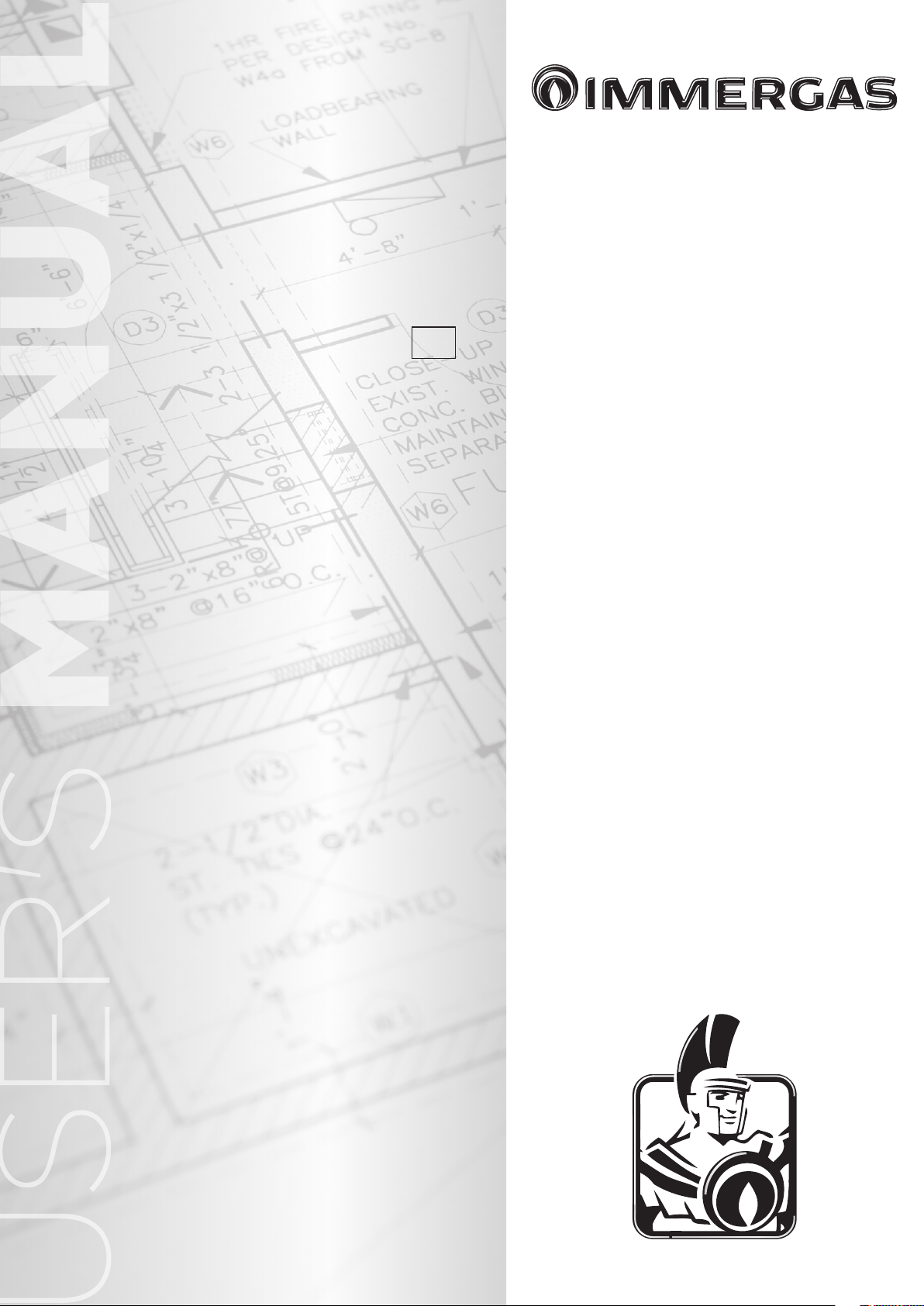
e wall surface must be smooth, without any
protrusions or recesses enabling access to the
rear part. ey are not designed to be installed
on plinths or oors (Fig. 1-1).
By varying the type of installation the
classication of the boiler also varies, precisely:
- Type C boiler Uses concentric or Coaxial pipes
systems Hunt Heating supplies the correct ue
for this application.
Only professionally heating/plumbing
technicians are authorised to install Immergas
gas appliances.
Installation must be carried out according to
regulation standards AS/NZS 5601 or Local
Authority laws.
Installation of the INTEC 12-30 SYSTEM
EXTERNAL boiler when powered by Universal
LPG must also comply with the rules regarding
gases with a greater density and be installed
to meet all local and AS/NZS 5601 LAWS.
Before installing the appliance, ensure that it
is delivered in perfect condition; if in doubt,
contact the supplier immediately. Packing
materials (staples, nails, plastic bags, polystyrene
foam, etc.) constitute a hazard and must be kept
out of the reach of children. Leave adequate
space above the boiler for possible water and
ue removal connections. Keep all ammable
objects away from the appliance (paper, rags,
plastic, polystyrene, etc.). Do not place household
appliances underneath the boiler as they could
be damaged if the safety valve intervenes (if not
conveyed away by a draining funnel), or if there
are leaks from the connections; on the contrary,
the manufacturer cannot be held responsible for
any damage caused to the household appliances.
In the event of malfunctions, faults or incorrect
operation, turn the appliance o immediately and
contact a qualied technician (e.g. Hunt Heating
Service Dept which has specically trained sta
and original spare parts). Do not attempt to
modify or repair the appliance alone.
Failure to comply with the above implies personal
responsibility and invalidates the warranty.
Installation Standards:
- Installations MUST comply with AS/NZS
5601 and Local laws. Use AS/NZS 5601 as
a guide for specic locations see below.
- Installation is prohibited on the vertical
projection of the cooking surface.
- Installation is also prohibited in places/
environments that constitute common parts
of oce condominiums such as stairs, cellars,
entrance halls, attics, los, escape routes,
etc. if they are not located inside technical
compartments under the responsibility of
each individual building and only accessible
to the user (for the features of the technical
compartments, see the technical standards in
force).
Attention: wall mounting of the boiler must
guarantee stable and ecient support for the
boiler.
Use the bracket supplied as standard, xing it
with proper plugs according to the wall type. e
installer is responsible for the choose of the correct
plugs, according to the technical standard. Place
the supplied bracket, following the indications
reported on drawing 1-3 preferring the holes
indicated in the before mentioned draw.
N.B.: to fix the bracket we suggest to use
hexagon screw or countersunk screw for plug.
ese boilers are used to heat water to below
boiling temperature in atmospheric pressure.
ey must be attached to a heating system suitable for their capacity and voltage.
YES NO
1-1
Flue terminal positions
Use as a guide only. Refer to AS/NZS 5601 or gas tting rules for specic location.
h
j
MAINTENANCE TECHNICIAN
j
W
f
c
k
j
D
I
k
Flue terminal positions. Shaded area indicates prohibited area
Ref. Item Min. Clearance mm
Below eaves, balconies and other projections (Appliances over 50MJ/h) 300
a
From the ground, above a balcony or other surface 300
b
From a return wall or external wall 300
c
From a gas meter 1000
d
From an electricity meter or fusebox/breaker panel 500
e
From a drain pipe or soil pipe 75
f
Horizontally from any building structure or obstruction facing a ue terminal 500
g
From any other ue terminal, cowl or combustion air intake 300
h
Horizontally from any opening window, door, non-mechanical air inlet or other opening into a building with the exception of sub-oor ventilation 300
j
From a mechanical air inlet including a spa blower 1000
k
Vertically below an opening window, non-mechanical air inlet or any other opening into a building with the exception of sub-oor ventilation 500
n
• e location of the ue terminal must comply with the clearances shown on this page.
If you are unsure about clearances not indicated here, in general
refer to AS/NZS 5601 or your local autority.
D - Door
a
T
e
h
h
T
g
e
P
c
d
g
M
k
b
T
I - Mechanical air inlet
M - Gas meter
T - Flue Terminal
W - Window
1-2
• All measurements are the minimum clearances required.
• Terminals must be positioned so to aviod combustion products
entering the building.
4
Page 5
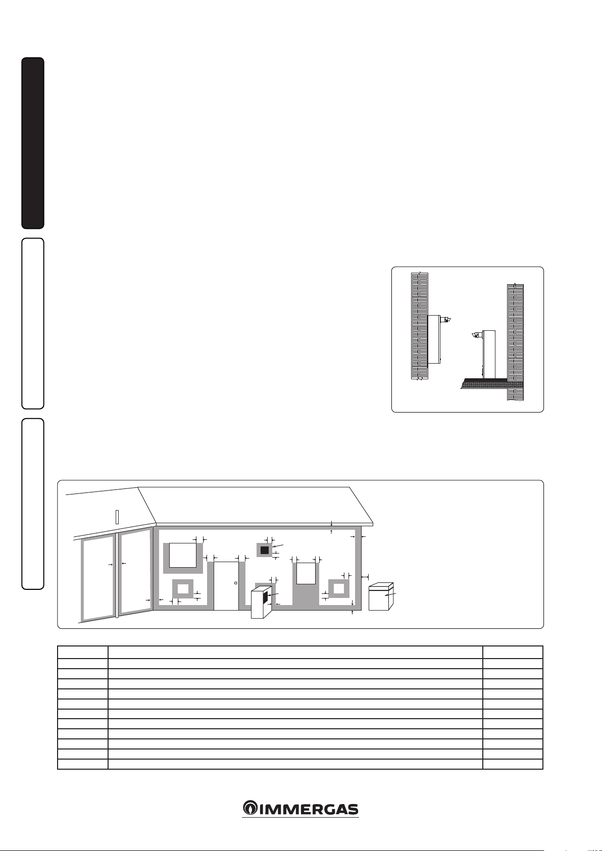
1.2 MAIN DIMENSIONS.
Height
(mm)
990 470 310
CONNECTIONS
CORD INLET GAS SYSTEM
C G R F
1/2” 3/4” 3/4” 3/4”
1.3 ANTIFREEZE PROTECTION.
Minimum temperature -5°C. e boiler comes
standard with an anti-freeze function that
activates the pump and burner when the system
water temperature in the boiler falls below 4°C.
e anti-freeze function is only guaranteed if:
- the boiler is correctly connected to gas and
electricity power supply circuits;
- the boiler is powered constantly;
- the boiler is not in no ignition block (Par. 2.5);
- the boiler essential components are not faulty.
In these conditions the boiler is protected against
freezing to an env ironmental temperature of -5°C.
Minimum temperature -15°C. If the boiler is
installed in a place where the temperature falls
below -5°C and in the event there is no gas, or
the boiler goes into ignition block, the appliance
may freeze.
To prevent the risk of freezing follow the
instructions below:
- Protect the central heating circuit from
freezing by introducing a good quality antifreeze liquid (specically for central heating
systems), (Fernox), carefully following the
manufacturer's instructions regarding the
percentage necessary with respect to the
Key:
G - Gas supply (not supplied as standard)
R - Return - CH
F - Flow - CH
SC - Condensate drain (supplied as standard)
(minimum internal diameter Ø13 mm)
C - Cold ll
Width
(mm)
Depth
(mm)
minimum temperature required for preserving
the system.
The boilers is made from materials that are
resistant to ethylene and propylene glycol-based
anti-freeze liquids.
For life and possible disposal, follow the
supplier's instructions.
- Protect the condensate drain trap and circuit
board against freezing by using an accessory
that is supplied on request (anti-freeze kit)
comprising two electric heating elements,
the relevant cables and a control thermostat
(carefully read the installation instructions
contained in the accessory kit pack).
Boiler anti-freeze protection is thus ensured only if:
- the boiler is correctly connected to gas and
electricity power supply circuits and powered;
- the anti-freezing kit components are ecient.
In these conditions the boiler is protected against
freezing to temperature of -15°C.
e warranty does not cover damage due to interruption of the electrical power supply and failure
to comply with that stated on the previous page.
N.B.: if the boiler is installed in places where the
temperature falls below 0°C the domestic water
and heating attachment pipes must be insulated.
1-3
1.4 CONNECTIONS.
Gas connection.
Our boilers are designed to operate with NG
and Universal LPG. Supply pipes must be sized
correctly to relevant gas codes.
Before connecting the gas line, carefully clean
inside all the supply pipes to remove any residue
that could impair boiler eciency. Also make
sure the gas corresponds to that for which
the boiler is prepared (see boiler data-plate).
If dierent, the appliance must be converted
for operation with the other type of gas (see
converting appliance for other gas types). e
dynamic gas supply (NG or Universal LPG)
pressure must also be checked according to
the type used in the boiler, which must be in
compliance, as insufficient levels can reduce
boiler output and cause malfunctions.
Ensure correct gas isolation valves connection.
e gas supply pipe must be suitably dimensioned
according to current regulations in order to
guarantee correct gas flow to the burner in
conditions of maximum boiler.
N.B.: there is a special adhesive label inside the
built-in frame displaying the layout of the boiler
connections.
Fuel gas quality. The appliance has been
designed to operate with gas free of impurities;
otherwise it is advisable to fit special filters
upstream from the appliance to restore the
purity of the gas.
Cold Water connection.
Attention: Filling the system, Hunt Heating
recommends the use of Auto fill valves sold
as an optional extra. Once satisfactory system
pressure is achieved, Auto ll valve MUST BE
TURNED OFF.
Attention: in order not to void the warranty
before making the boiler connections, carefully
clean the heating system on the primary heat
exchanger (pipes, radiators, etc.) with special
cleaning products (Fernox) to remove any
deposits that could compromise correct boiler
operation.
Chemical treatment of the heating system water
is required, in compliance with the technical
standards in force, in order to protect the system
and the appliance from deposits (e.g., lime scale),
slurry or other hazardous deposits. Products like
Fernox are suitable for this appliacation. Use
of backow devices are maditory when using
chemicals/water treatments or alternatively,
ensure physical air break.
Heating Water connections must be made using
approved valves this helps with maintenance and
servicing. Hunt Heating can provide valves as
optional extras.
e boiler safety valve outlet must be connected
to a Tun Dish or Directly to a suitable overow
outlet.
INSTALLERUSER
MAINTENANCE TECHNICIAN
5
Page 6
Condensate drain. To drain the condensate
produced by the appliance, it is necessary to
connect to the sewer system by means of acid
condensate resistant pipes i.e. p.v.c. having an
internal diameter of at least 13 mm. e system
connecting the appliance to the drainage system
must be carried out in such a way as to prevent
freezing of the liquid contained. Connections
must comply with national and local regulations
on discharging to waste waters, condensate must
not discharge to storm water. Pipes must be on
gradient to drain.
INSTALLERUSER
N.B.: ll the trap with water before operating
the boiler.
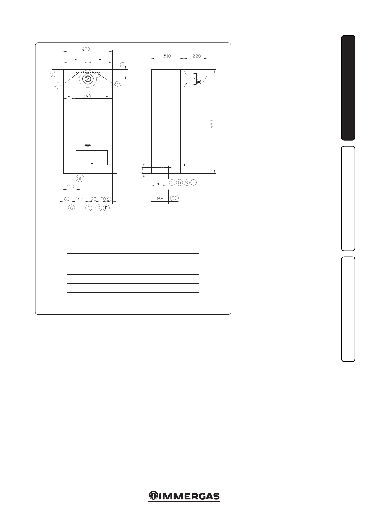
Electrical connection: The “INTEC 12-30
SYSTEM EXTERNAL” boiler has an IPX5D
protection rating for the entire appliance.
Electrical safety of the appliance is reached only
when it is correctly connected to an ecient
earthing system as specied by current safety
standards.
Attention: Immergas/Hunt Heating declines
any responsibility for damage or physical injury
caused by failure to connect the boiler to an
ecient earth system or failure to comply with
the reference standards.
Also ensure that the electrical installation
corresponds to maximum absorbed power
specifications as shown on the boiler dataplate. The boilers come complete with a 1.5
metre power cable that includes an Australian
electrowelded plug. The plug is of type I,
compliant with standard AS 3112. e power
cable must be connected to a 240V ±10% / 50Hz
mains respecting L-N polarity and the earth
connection
. When replacing the power
supply cable, contact a qualied technician (e.g.
Hunt Heating Service Dept) (Fig. 1-4).
In the event of mains fuses replacement on the
connection board, use 3.15A fast fuses. For the
main power supply to the appliance, never use
adapters, multiple sockets or extension leads.
Note: If the condensate cannot be on a gradient
and terminate to drain, then a suitable condensate
neutraliser must be used (available for purchase
from Hunt Heating).
1.5
REMOTE CONTROL CARV2
OPTIONAL.
e boiler is prepared for the application remote
control CAR
(Fig. 1-5).
Immergas remote control CAR
V2
, which is available as optional kit.
V2
is connected
with 2 wires only. Carefully read the user and
assembly instructions contained in the accessory kit.
• In addition to the functions described in the
previous point, the CAR panel
V2
enables the
user to control all the important information
regarding operation of the appliance and the
heating system with the opportunity of easily
intervening on the previously set parameters
without having to go to the place where
the appliance is installed. e CAR
V2
panel
is equipped with self-diagnosis to display
any boiler functioning abnormalities. The
climate chrono-thermostat incorporated into
the remote panel enables the system flow
temperature to be adjusted to the actual needs
of the room being heated, in order to obtain
the desired room temperature with extreme
precision and therefore with evident saving in
running costs. e chrono-thermostat is fed
directly by the boiler by means of the same 2
wires used for the transmission of data between
boiler and chrono-thermostat.
V2
CAR
(Optional). e operations described
below must be performed aer having removed
the voltage from the appliance. Any CARV2 must
be connected by means of terminals IN+ and
IN- (on the CAR
V2
terminal plate), respecting
polarity at boiler PCB, where IN+ connects to
terminal 44 and IN- connects to terminal 41
(See Fig. 1-6).
Attention: if the Comando Amico Remoto
V2
(CARV2) remote control is used, arrange two
separate lines in compliance with current
regulations regarding electrical systems. No
boiler pipes must ever be used to earth the
electric system or telephone lines.
Ensure elimination of this risk before making
the boiler electrical connections (ALL
ELECTRICAL CONNECTION MUST MEET
ALL LOCAL REGULATIONS).
1.6 EXTERNAL PROBE OPTIONAL.
e boiler is prepared for the application of the
external probe (Fig. 1-7), which is available as an
optional kit. Refer to the relative instruction sheet
for positioning of the external probe.
The probe can be connected directly to the
boiler electrical system and allows the max.
system ow temperature to be automatically
decreased when the external temperature
increases, in order to adjust the heat supplied to
the system according to the change in external
temperature. e external probe always operates
when connected, regardless of the presence or
type of room chrono-thermostat used and can
work in combination with Immergas chronothermostats. e correlation between system
flow temperature and external temperature
is determined by the position of the selector
switch on the boiler control panel according to
the curves shown in the diagram (Fig. 1-8). e
electric connection of the external probe must be
made on clamps 38 and 39 on the boiler P.C.B.
(Fig. 3-2).
NB: Thermostat connections if using own
after market thermostat, after removing
manufacturers link, connect to terminals 40
and 41 (Fig. 3-2).
MAINTENANCE TECHNICIAN
31
POWER SUPPLY CABLE
45
58
1-4
1-7
1-5 1-6
Position of the central heating temperature
user adjustment
1-8
6
Page 7

1.7 IMMERGAS FLUE SYSTEMS.
Immergas supplies various solutions separately
from the boilers regarding the installation of air
intake terminals and ue extraction, which are
fundamental for boiler operation.
Attention: the boiler must be installed
exclusively with an original Immergas “Green
Range” air intake and fume extraction system
in plastic, as envisioned by the Standards
in force. is system can be identied by an
identification mark and special distinctive
marking bearing the note: “only for condensing
b oi l er s ”.
• Resistance factors and equivalent lengths.
Each ue component has a Resistance Factor
based on experimental tests and specified
in the table below. e Resistance Factor for
individual components is independent from
the type of boiler on which it is installed
and has a dimensionless size. It is however,
conditioned by the temperature of the uids
that pass through the pipe and therefore,
varies according to applications for air intake
or ue exhaust. Each single component has a
resistance corresponding to a certain length
in metres of pipe of the same diameter; the
so-called equivalent length, obtained from the
ration between the relative Resistance Factors.
All boilers have an experimentally obtainable
maximum Resistance Factor equal to 100.
The maximum Resistance Factor allowed
corresponds to the resistance encountered with
the maximum allowed pipe length for each
type of Terminal Kit. is information allows
calculations to be made to verify the possibility
of setting up various ue congurations.
Positioning of the gaskets (black) for “green
range” ue extraction systems. Position the
gasket correctly (for bends and extensions) :
- gasket with notches, to use for bends;
- gasket without notches, to use for extensions.
N.B.: if component lubrication (already carried
out by the manufacturer) is not sucient, remove
the residual lubricant using a dry cloth, then to
ease tting spread the elements with common
or industrial talc.
With ue gaskets installed correctly, gently push
ue components together fully.
N.B.: considerations need to be made when
sighting/terminating ue extraction system as
an element of plumage will occur when boiler
is in operation.
N.B.: for safety purposes, do not obstruct the
boiler intake-exhaust terminal, even temporarily.
INSTALLERUSER
MAINTENANCE TECHNICIAN
7
Page 8
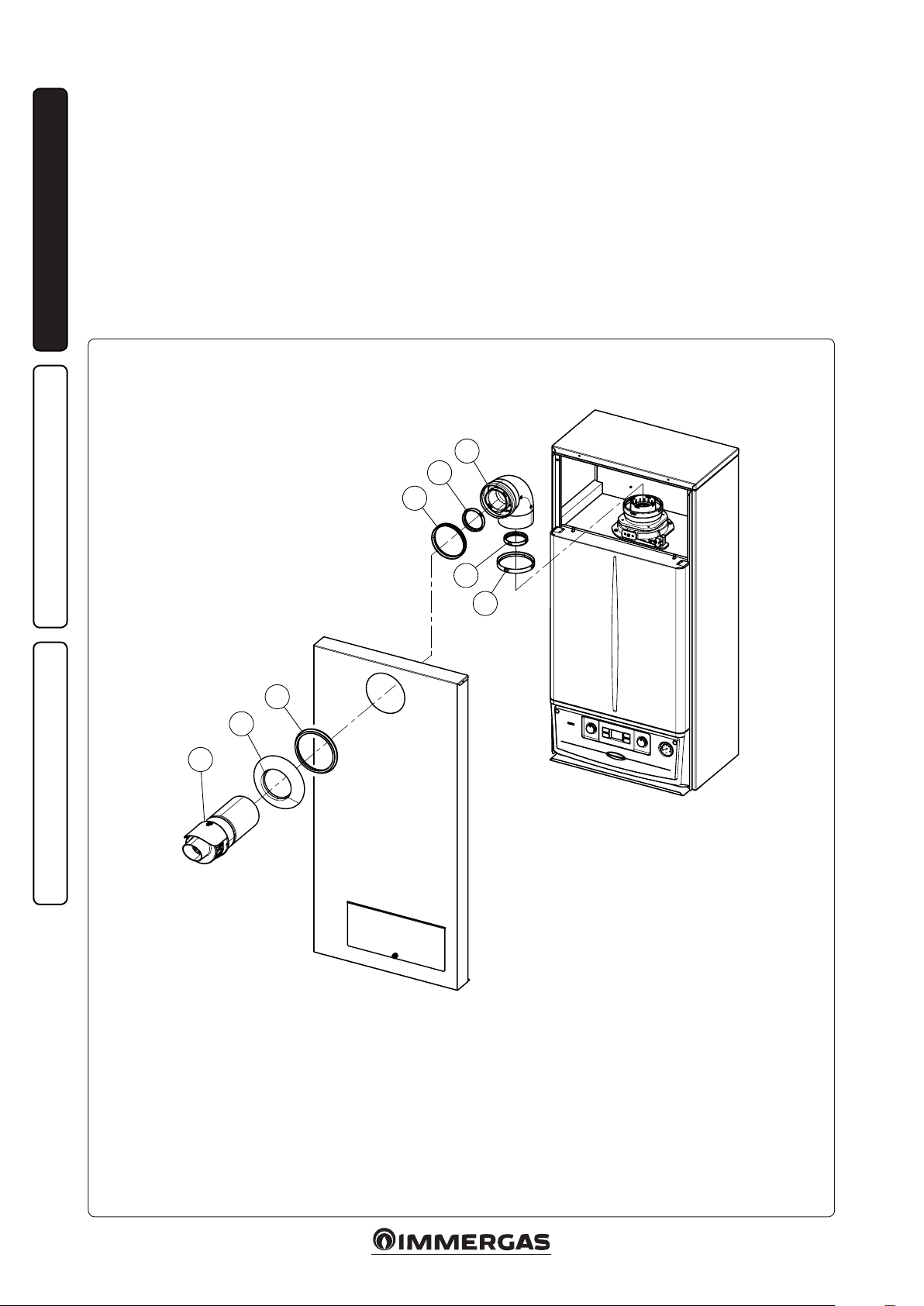
1.8 INSTALLATION OF INTAKE /
EXHAUST TERMINALS.
• Type C conguration, sealed chamber and
fan assisted.
Horizontal intake - exhaust terminal Ø60/100
(supplied as standard). Assembly (Fig. 1-9):
install the gaskets (1) and (2) in the concentric
ange (already installed).
Couple the bend (3) with the concentric ange up
to the stop aer having checked that the gaskets
are tted (4) and (5) in the female end.
Mount the casing front referring to Paragr. 3.14.
INSTALLERUSER
Couple the terminal pipe (8) with the male end
(smooth) into the female end (with lip seals) of
the bend (3) up to the stop, making sure that
the external wall sealing plate (7) has been tted
and checking it is on the casing front and gasket
(6); this will ensure proper sealing and joining
of the elements.
N.B.: Flue conguration supplied standard
with all INTEC external boilers.
6
7
8
C
12
3
4
5
2
1
MAINTENANCE TECHNICIAN
Components:
Concentric ange intake gasket (1)
Concentric ange exhaust gasket (2)
90° concentric bend (3)
90° concentric bend exhaust gasket (4)
90° concentric bend intake gasket (5)
Gasket (6)
External wall sealing plate (7)
Concentric intake/exhaust terminal Ø 60/100 (8)
Flue kit complete 60/100 Australia code: 3.026007
1-9
8
Page 9
1.9 SYSTEM FILLING.
Once the boiler is connected, proceed with
system lling through the arranged lling valve,
which can be connected to the return pipe system
and as close as possible to the boiler (Fig. 1-11),
or ideally via connection ‘C’.
Filling is performed at low speed to ensure release
of air bubbles in the water via the boiler and
heating system vents.
e boiler has a built-in automatic venting valve
on the circulator. Check if the cap is loose. Open
the radiator air vent valves.
Close radiator vent valves when only water
escapes from them.
Close the lling valve when the boiler manometer
indicates approx. 1.2 bar.
N.B.: during these operations, turn on the circulating pump at intervals by means of the main
selector switch on the control panel. Vent the
circulation pump by loosening the front cap and
keeping the motor running. Only open for a few
seconds at a time.
In presence of the automatic lling, the auto ll
valve must necessarily be isolated aer system
is pressurized.
1.10 GAS SYSTEM STARTUP.
To start up the system, make reference to the
Standard: is divides the systems and therefore
the start-up operations into three categories: new
systems, modied systems, re-activated systems.
In particular, for new gas systems:
- open windows and doors;
- avoid presence of sparks or naked ames;
- bleed all air from pipelines;
- check that the internal system is properly sealed
according to specications.
1.11 BOILER START UP IGNITION.
For first ignition, the following must be
performed:
- check that the internal system is properly sealed
according to specications;
- ensure that the type of gas used corresponds
to boiler settings;
- switch the boiler on and ensure correct
ignition;
- make sure that the gas ow rate and relevant
pressure values comply with those given in the
manual;
- ensure that the safety device is engaged in the
event of gas supply failure and check activation
time;
- check activation of the master switch located
upstream from the boiler and in the boiler;
- check that the intake/exhaust concentric
terminal (if tted) is not blocked.
e boiler must not be started up even if only
one of the checks should be negative.
N.B.: the boiler preliminary check must be carried
out by a qualied technician. e conventional
boiler warranty is valid as of the date of testing if
not commissioned by a qualied technician.
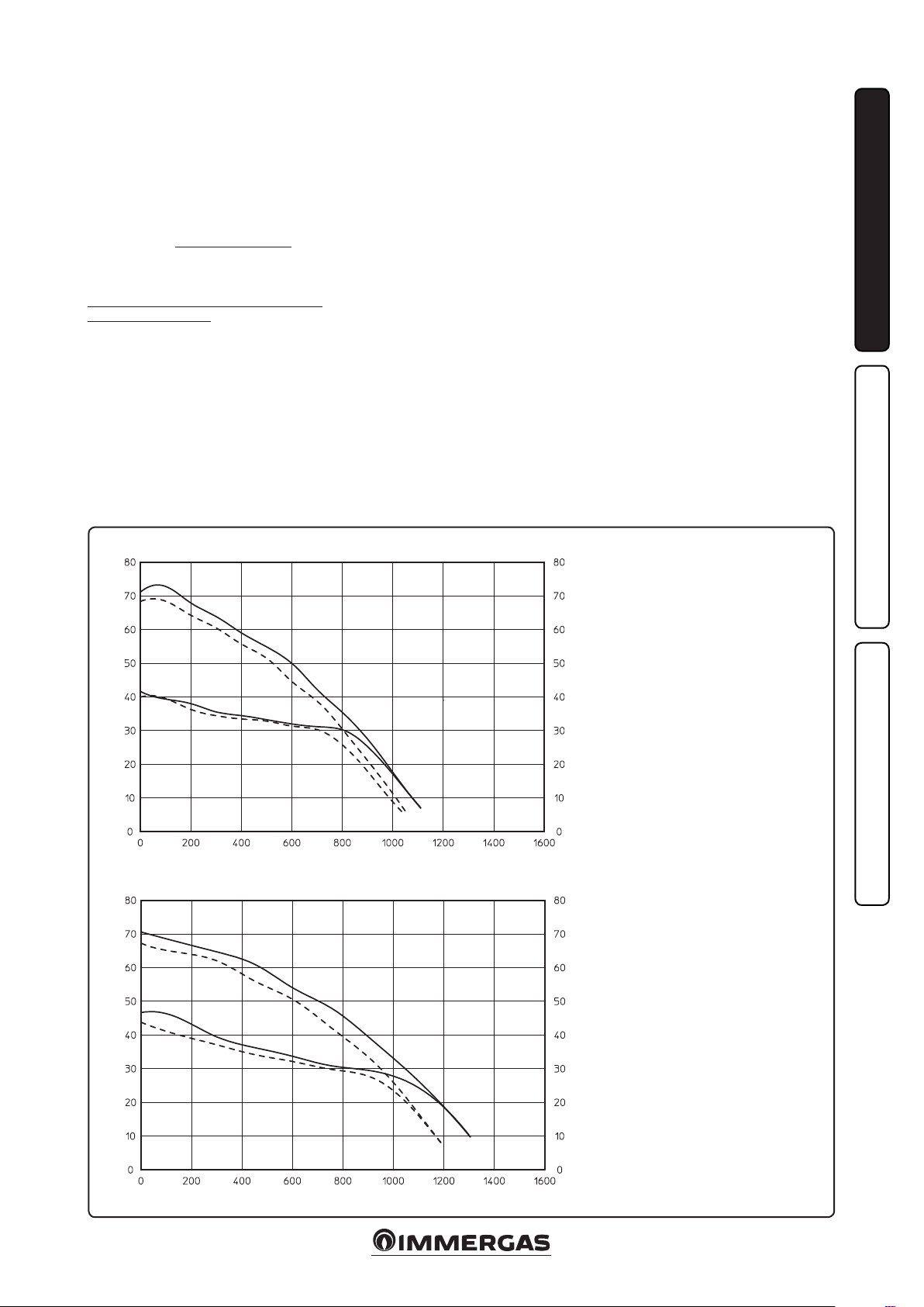
1.12 CIRCULATION PUMP.
e “INTEC 12-30 SYSTEM EXTERNAL” series
boilers are supplied with a built-in circulation
pump with 3-position electric speed control.
e boiler does not operate correctly with the
circulation pump on speed one. To ensure
optimal boiler operation, in the case of new
system it is recommended to use the pump at
maximum speed, position 3.
Pump release. If, aer a prolonged period of
inactivity, the circulation pump is blocked,
unscrew the front cap and turn the motor sha
using a screwdriver. Take great care during this
operation to avoid damage to the motor.
INSTALLERUSER
Head available to the system (INTEC 12).
C
Head (kPa)
Head available to the system (INTEC 30).
A
D
B
C
B
Flow rate (l/h)
A
O)
2
Head (m H
A = Head available to the system at maxi-
mum speed with by-pass closed.
B = Head available to the system at maxi-
mum speed with by-pass open.
C = Head available to the system at second
speed with by-pass closed.
D = Head available to the system at second
speed with by-pass open.
O)
2
1-10
MAINTENANCE TECHNICIAN
Head (kPa)
D
Flow rate (l/h)
Head (m H
9
Page 10
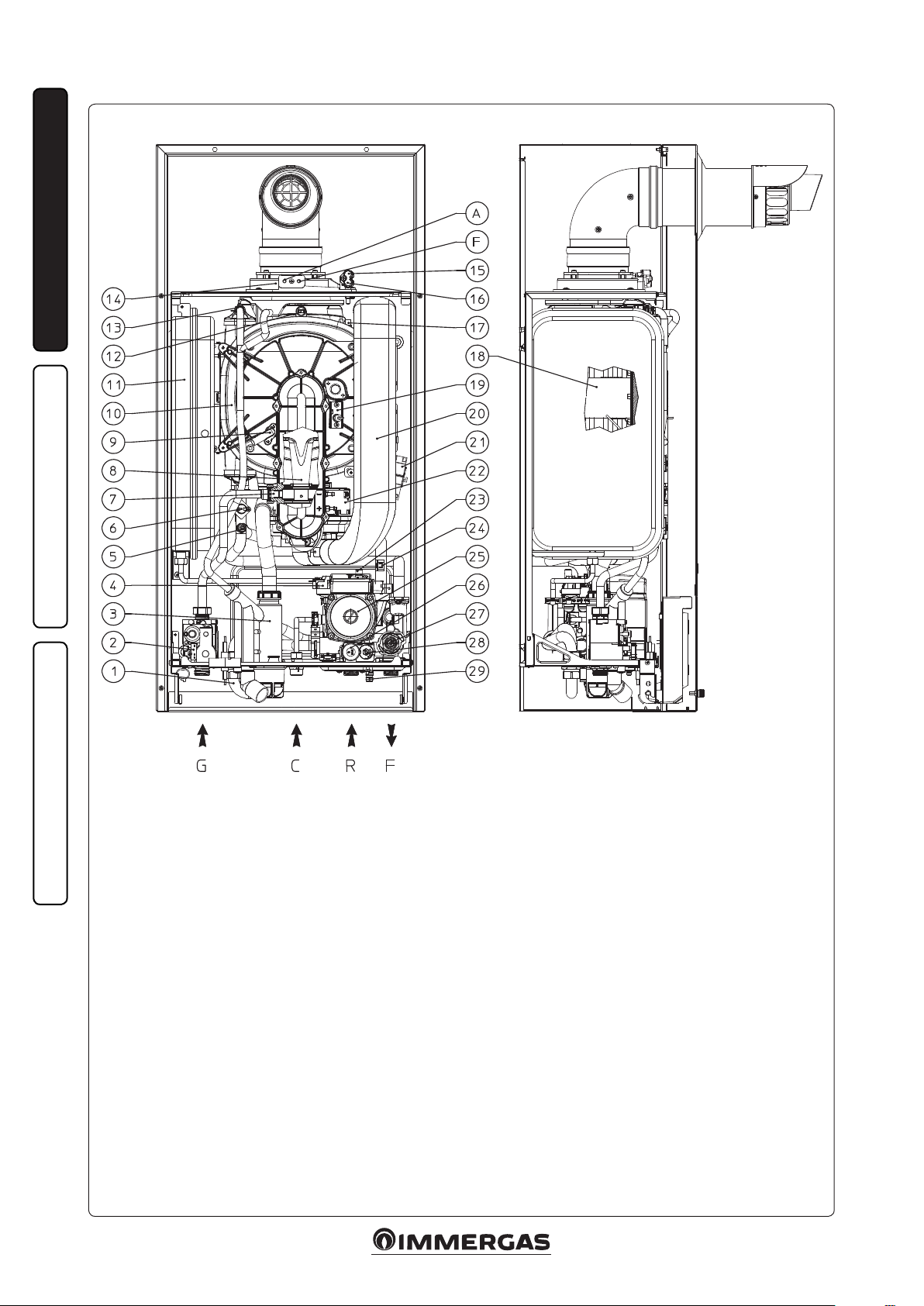
1.13 BOILER COMPONENTS.
INSTALLERUSER
MAINTENANCE TECHNICIAN
Key:
1 - Storage tank unit delivery return by-pass
2 - Gas valve
3 - Condensate drain trap
4 - System pressure switch
5 - Flow probe
6 - Safety thermostat
7 - Gas nozzle
8 - Venturi
9 - Detection electrode
10 - Condensation module
11 - System expansion vessel
12 - Flue probe
13 - Manual air vent valve
14 - Sample points (air A) - (ue gases F)
G - Gas supply
R - Return
F - Flow
C - Cold ll
15 - Negative signal pressure point
16 - Positive signal pressure point
17 - Heat exchanger safety thermofuse
18 - Burner
19 - Ignition electrode
20 - Air intake pipe
21 - Igniter
22 - Fan
23 - Air vent valve
24 - Return probe
25 - Boiler pump
26 - 3 bar safety valve
27 - 3-way valve (motorised)
28 - By-pass
29 - System draining valve
1-11
10
Page 11
INSTRUCTIONS FOR USE
2
AND MAINTENANCE.
2.1 CLEANING AND MAINTENANCE.
Attention: the boiler and heating systems must
undergo periodical maintenance, combustion
and energy eciency checks in compliance with
AS/NZS 5601, by a qualied licensed operative.
this insure that optimal safety performance
and operation of the boiler remains unchanged
over time.
We recommend your appliance is serviced every
24 months (see Par. 3.16).
2.2 GENERAL WARNINGS.
Use of the boiler by unskilled persons or children
is strictly prohibited.
If temporary shutdown of the boiler is required,
proceed as follows:
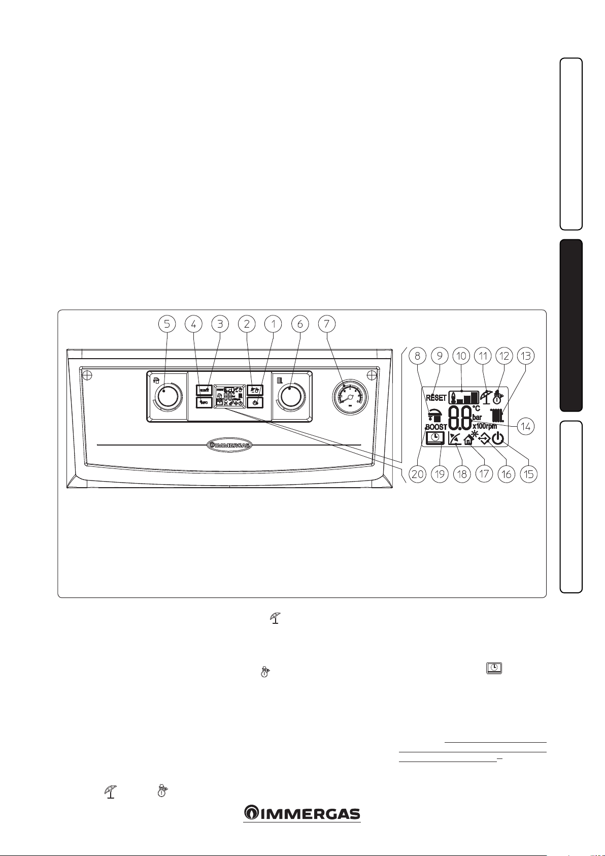
2.3 CONTROL PANEL.
2-1
a) drain the heating system if anti-freeze is not
used;
b) shut-o all electrical, water and gas supplies.
In the case of work or maintenance to structures
located in the vicinity of ducting or devices for
ue extraction and relative accessories, switch o
the appliance and on completion of operations
ensure that a qualied licensed operative checks
eciency of the ducting or other devices.
Never clean the appliance or connected parts
with easily ammable substances.
Never leave containers or ammable substances
in the same environment as the appliance.
• Attention: the use of components involving use
of electrical power requires some fundamental
rules to be observed:
- do not touch the appliance with wet or moist
parts of the body; do not touch it when
barefoot;
- the appliance power cable must not be replaced
by the user;
- in the event of damage to the cable, switch
off the appliance and contact a qualified
technician;
- if the appliance is not to be used for a certain
period, disconnect the main power switch.
INSTALLERUSER
Key:
1 - O/Stand-by/On Button
2 - Summer/Winter Button
3 - Reset button
4 - Information buttons
5 - Domestic hot water temperatureselector
switch
6 - Central heating water temperature selector
switch
7 - Boiler manometer
To access the control panel, remove the protection panel (6) from the casing front by unscrewing the bolt (7) and removing it as shown in
Fig. 3-4a.
2.4 USING THE BOILER.
Before ignition make sure the heating system
is lled with water and that the manometer (7)
indicates a pressure of 1 ÷ 1.2 bar (Fig. 2-1).
- Open the gas cock upstream from the boiler.
- Press the button (1) until the display switches
on. At this point, the boiler goes to the state
previous to switch-o.
- If the boiler is in stand-by, press the button (1)
again to activate it. If this is not the case, go to
the next point.
- Press button (2) in sequence and take the boiler
to summer (
) or winter ( ) position.
8 - DHW production phase functioning active
9 - Boiler in block does not require release via
“RESET” button
10 - Flame presence symbol and relative power
scale
11 - Functioning in summer mode
12 - Functioning in winter mode
13 - Room central heating active phase functio-
ning
• Summer (
functions only to produce the DHW, the
temperature is set via the selector (5) and the
relative temperature is shown on the display
via the indicator (14).
• Winter (
both for producing domestic hot water and
heating the environment. e temperature of
the DHW is always regulated via the selector
(5), the heating temperature is regulated via
selector (6) and the relative temperature is
shown on the display via the indicator (14).
From this moment the boiler functions
automatically. With no demand for heat (heating
or domestic hot water production) the boiler
goes to “standby” function, equivalent to the
boiler being powered without presence of ame.
): in this mode the boiler
): in this mode the boiler functions
14 - Temperature indicator, boiler info and
error codes
15 - Boiler in Stand-by mode
16 - Presence of external connected devices
17 - Solar function active
18 - Functioning with external temperature
probe active (optional)
19 - Boiler connected to remote control V2
(optional)
20 - Not used on this model
Each time the burner ignites, the relative ame
present symbol is displayed (10) with relative
power scale.
• Operation with Comando Amico Remoto
remote control
V2
is connected, the ( ) symbol will
CAR
appear on the display. e boiler regulation
parameters can be set via the CARV2 control
panel and the reset button (3) remains active
on the boiler control panel, along with the
switch-o button (1) (“o ” mode only) and the
display where the functioning state is shown
Important: if the boiler is put into “off ”
mode, the “ERR>CM” connection error
symbol will appear on the CAR
however powered constantly so as not to loose
memorised programs.
V2
(CARV2) (Optional). If the
V2
. e CAR V2is
MAINTENANCE TECHNICIAN
11
Page 12

• Solar functioning mode ( ). is function
is activated automatically if the boiler detects
a probe on the DHW inlet (optional) or if the
“Solar ignition delay” parameter is more than
0 seconds.
During a withdrawal, if the outlet water is
hot enough, the boiler does not switch on,
the DHW withdrawal symbol (
on the display along with the ashing solar
function symbol (
INSTALLERUSER
When the water supplied by the solar system
is at a temperature lower than that at which
the boiler is set, the boiler switches on. At this
point, the solar function symbol will stay on
without ashing.
• Functioning with optional external probe
(
). In the case of a system with optional
external probe, the boiler ow temperature
for room central heating is managed by the
external probe depending on the external
temperature measured (Par. 1.6). The flow
temperature can be modied by selecting the
functioning curve via the selector switch (6)
(or on the CARV2 control panel, if connected
to the boiler) selecting a value from “0 to 9”.
).
) appears
With external probe present, the relative
symbol (18) will appear on the display. In the
central heating phase, if the temperature of the
water contained in the system is sucient to
heat the radiators, the boiler can only function
with the activation of the pump.
• “Stand-by” mode. Press button (1) in
succession until the (
e boiler remains inactive from this moment
and the anti-freeze function, pump anti-block
function and 3-way and signalling of any
anomalies is guaranteed.
N.B.: in these conditions the boiler is
considered still powered.
• “O” mode. By holding the button (1) down
for 8 seconds, the display switches-o and the
boiler is o completely. e safety functions are
not guaranteed in this mode.
N.B.: in these conditions the boiler is considered
still live even if there are no functions active.
• “Automatic vent” mode. Every time power is
supplied to the boiler. the system automatic
vent function is activated (duration 8 minutes).
This function is displayed via countdown
signalled by the indicator (14). During this
period the DHW and CH functions are not
active.
The “automatic vent” can be annulled by
pressing the “reset” button (3).
) symbol appears.
• Display functioning. e display lights up
during the use of the control panel, aer 15
seconds inactivity, the brightness drops until
just the active symbols are displayed. The
lighting mode can be varied via parameter t3
in the circuit board customisation menu.
2.5 FAULT AND ANOMALY SIGNALS.
e INTEC 12-30 SYSTEM EXTERNAL boiler
signals any anomalies using a code shown on
the boiler display (14) according to the following table.
On the CAR
by means of the same numeric code represented
according to the following example (e.g. CARV2
= Exx).
V2
, the error code will be displayed
Error
Code
Anomaly signalled Cause Boiler status / Solution
In the event of request of room central heating or domestic hot water
01 No ignition block
Safety thermostat
02
block (overheating)
Flue safety thermo-
03
stat block
Contacts resistance
04
block
05 Flow probe anomaly e board detects an anomaly on the ow NTC probe. e boiler does not start (1).
Domestic hot water
06
probe anomaly
production, the boiler does not switch on within the preset time. Upon
appliance commissioning or aer extended downtime, it may be necessary to eliminate the block.
During normal operation, if a fault causes excessive overheating internally,
the boiler goes into overheating block.
During normal operation, if a fault causes excessive ue gas overheating,
the boiler blocks
e P.C.B. detects an anomaly on the gas valve supply. Check the connection. (the anomaly is detected and displayed only in the event of a request).
e board detects an anomaly on the domestic hot water NTC probe.
MAINTENANCE TECHNICIAN
Maximum N° of
08
reset
Insufficient system
10
pressure
15 Conguration error
16 Fan anomaly is occurs if the fan has a mechanical or electrical fault. Press the Reset button (1).
20 Parasite ame block
Return probe anom-
23
aly
(1) If the shutdown or fault persists, contact an authorised company (e.g. Authorised Technical Aer-Sales Service).
Number of allowed resets that have already performed.
Water pressure inside the central heating circuit that is sucient to guarantee the correct operation of the boiler is not detected.
If the board detects an anomaly or incongruity on the electric wiring, the
boiler will not start.
is occurs in the event of a leak on the detection circuit or anomaly in
the ame control unit.
e board detects an anomaly on the return NTC probe e boiler does not start (1).
Press the Reset button (1).
Press the Reset button (1).
Press the Reset button (1).
e boiler does not start (1).
In this case the boiler continues to produce
domestic hot water but not with optimal
performance. Moreover, the antifreeze
function (1) is restrained.
Attention: the anomaly can be reset 5 times
consecutively, aer which the function in
inhibited for at least one hour. One attempt
is gained every hour for a maximum of 5
attempts. By switching the appliance on and
o the 5 attempts are re-acquired.
Check on the boiler pressure gauge (1) that
the system pressure is between 1÷1.2 bar
and restore the correct pressure if necessary.
If normal conditions are restored the boiler
restarts without having to be reset. Check
that the boiler is congured correctly (1).
Press the Reset button (1).
12
Page 13

Error
Code
(1) If the shutdown or fault persists, contact an authorised company (e.g. Authorised Technical Aer-Sales Service).
Anomaly signalled Cause Boiler status / Solution
Push button control
24
panel anomaly
Block due to ue gas
25
temperature gradient intervention
Insucient circula-
27
tion
29 Flue probe anomaly
Loss of remote con-
31
trol communication
IMG Bus communi-
36
cation loss
Low power supply
37
voltage
38 Loss of ame signal
Block due to loss
43
of continue flame
signal
Block for exceeding
the maximum accu-
44
mulated time, close
gas valve opening
45 High T
Low temperature
46
safety thermostat
(optional)
Burner power limi-
47
tation
High temperature
49
block on return
probe
e board detects an anomaly on the pushbutton panel
If the board detects a rapid increase in ue gas temperature probably due
to a blocked circulating pump or lack of water in the heat exchanger, the
boiler shuts down due to the ue gas temperature gradient trip.
is occurs if there is overheating in the boiler due to insucient water
circulating in the primary circuit; the causes can be:
- low system circulation; check that no shut-o devices are closed on the
heating circuit and that the system is free of air (deaerated);
- pump blocked; free the pump.
If the board detects an anomaly on the ue gas probe the boiler will not
start
is occurs 1 minute aer communication is lost between the boiler and
the remote control.
Communication between the various components is interrupted due to
an anomaly on the boiler control unit, on the zone control unit or on
the IMG Bus.
is occurs when the power supply voltage is lower than the allowed limits
for the correct boiler operation.
is occurs when the boiler is ignited correctly and the burner ame
switches o unexpectedly; a new ignition attempt is performed and if
normal conditions are restored, the boiler does not need to be reset (this
fault can be checked in the list of errors in the “Information” menu only).
is occurs if the ''Flame signal loss'' error occurs many times in a row
within a preset period (38).
is occurs if the gas valve remains open for longer than required for
normal operation, without the boiler switching on.
If the board detects a sudden and unexpected rise in ΔT between the
system ow probe and return probe, the boiler limits the burner output
to prevent damaging the condensing module; when the correct ΔT has
been restored, the boiler returns to normal operation.
During normal operation, if an anomaly causes excessive overheating of
the ow temperature in low temperature conditions, the boiler blocks.
Should ue high temperature be detected, the boiler reduces power supplied so as not to damage it.
is occurs when the heat exchanger return circuit reaches too high of
a temperature.
If normal conditions are restored the boiler
restarts without having to be reset (1).
Press the Reset button (1).
Press the Reset button (1).
e boiler does not start (1).
Power cycle the boiler. If the Remote
Control is still not detected on re-starting
the boiler will switch to local operating
mode, i.e. using the controls on the control
panel (1).
e boiler does not satisfy the room heating
requests (1).
If normal conditions are restored the boiler
restarts without having to be reset (1).
If normal conditions are restored the boiler
restarts without having to be reset (1).
Press the Reset button, before restarting, the
boiler will run a post-ventilation cycle (1).
Press the Reset button (1).
Make sure there is water circulating in the
boiler, that the pump is congured according to system requirements and that the
return probe works properly (1).
In this case, aer suitable cooling, it is possible to reset the thermostat (see relative
instructions sheet) (1).
(1).
Make sure that water circulates properly
in the boiler and that the three-way valve
works properly. To eliminate it, the Reset
button (C) must be pressed (1).
INSTALLERUSER
MAINTENANCE TECHNICIAN
13
Page 14

2.6 INFORMATION MENU.
By pressing the “Info” button (4), the “Information
menu” is activated, which lists boiler functioning
information.
Press the “Info” button (4) to scroll the various
information.
To exit the menu, press the “Info” button (4) up
to the end of the list, or by pressing the “Reset”
button (3) or by waiting for 15 minutes.
With the menu active, the indicator (14) will
alternately show the indication of the parameter
via the letter “d” plus the number of the
parameter that is being displayed and the value
of the parameter itself.
Id
Parameter
d1 Displays the ame signal (uA x 10 approximate)
INSTALLERUSER
d2 Displays the primary exchanger output instant heating ow temperature
d3 Displays the instant output temperature from the DHW exchanger
d4 Displays the values set for central heating set
d5 Displays the values set for DHW set
Displays the external temperature (if external probe present)
d6
If the temperature is below zero, the value is displayed ashing.
d7 Display the temperature of the inlet DHW (with DHW inlet probe present)
d8 Display the temperature of the return probe.
Displays the list of the last ve anomalies.
d9
(to scroll the list, turn the CH temperature selector (6))
2.7 BOILER SHUTDOWN
Switch the boiler o by pressing the “
disconnect the power supply outside of the boiler
and close the gas cock upstream of the appliance.
Never leave the boiler switched on if le unused
for prolonged periods.
2.8 RESTORING CENTRAL HEATING
SYSTEM PRESSURE.
Periodically check the system water pressure.
e boiler pressure gauge should read a pressure
between 1 and 1.2 bar.
If the pressure falls below 1 bar (with the circuit
cold) restore normal pressure via the ll valve.
N.B.: close the cock aer the operation.
If pressure values reach around 3 bar the safety
valve may be activated.
In the event of frequent pressure drops, contact
original installer or qualied licensed operative
for assistance to eliminate possible system
leakage.
” button,
Description
2.9 DRAINING THE SYSTEM.
To drain the boiler, use the special system
draining valve (Fig. 1-11, Part. 29).
Before draining, ensure that the system lling
valve is closed.
2.10 ANTIFREEZE PROTECTION.
The boiler has an anti-freeze function that
switches on automatically when the temperature
falls below 4°C (standard protection to minimum
temperature of -5°C). All information relative to
the anti-freeze protection is stated in Par. 1.3. In
order to guarantee the integrity of the appliance
and the domestic hot water heating system in
zones where the temperature falls below zero,
we recommend the central heating system is
protected using anti-freeze liquid and installation
of the Immergas Anti-freeze Kit in the boiler. In
the case of prolonged inactivity (second case),
we also recommend that:
- the electric power supply is disconnected;
- the heating circuit and boiler domestic water
circuit must be drained. In systems that are
drained frequently, filling must be carried
out with suitably treated water to eliminate
hardness that can cause lime-scale.
2.11 CASE CLEANING.
Use damp cloths and neutral detergent to clean
the boiler casing. Never use abrasive or powder
detergents.
2.12 DECOMMISSIONING.
In the event of permanent shutdown of the
boiler, contact an authorised company for
the procedures and ensure that the electrical,
water and gas supply lines are shut off and
disconnected.
MAINTENANCE TECHNICIAN
14
Page 15

BOILER COMMISSIONING
3
INITIAL CHECK.
When commissioning the boiler, ensure the
appliance checklist, located at the rear of this
instruction booklet is completed.
To commission the boiler:
- ensure that the type of gas used corresponds to
boiler settings recorded on the appliance data
plate;
- check connection to a 230V-50Hz power
mains, correct L-N polarity and the earthing
connection;
3.1 HYDRAULIC DIAGRAM.
Key:
1 - Condensate drain trap
2 - 3 bar safety valve
3 - Gas valve
4 - Gas valve outlet pressure point (P3)
5 - Venturi positive sign (P1)
6 - Venturi negative sign (P2)
7 - Air/gas Venturi manifold
8 - Fan
9 - Gas nozzle
10 - Detection electrode
11 - Flue probe
12 - Air intake pipe
13 - Condensation module
14 - Manual air vent valve
15 - Heat exchanger safety thermofuse
16 - Air sample point
17 - ∆p gas pressure point
18 - Flue sample point
19 - Flue hood
20 - Safety thermostat
21 - Flow probe
22 - Ignition electrode
23 - Burner
24 - Condensation module cover
25 - Return probe
26 - System expansion vessel
27 - Air vent valve
28 - Boiler pump
29 - System draining valve
30 - System pressure switch
31 - 3-way valve
32 - By-pass
- switch the boiler on and ensure correct ignition;
- ensure the gas inlet working pressure is correct,
1.1 Kpa (Natural Gas), 2.75 Kpa (LPG);
- check and set expansion vessel air pressure to
1 bar;
- pre ll condense trap with clean water;
- ll and set system pressure to 1.2 bar;
- vent air from boiler and system, also allow
automatic vent function to run (Par. 3.13);
- check that the gas maximum and minimum
relative pressure values correspond to those
given in the handbook, Par. 3.15;
- check activation of the safety device in the event
of no gas, as well as the relative activation time;
- check activation of the main switch located
upstream from the boiler and in the boiler;
- check that the intake and/or exhaust terminals
are not blocked;
- ensure activation of all adjustment devices;
- ensure sealing eciency of hydronic circuits;
- check ventilation and/or aeration of the
installation room where provided.
INSTALLERUSER
MAINTENANCE TECHNICIAN
G - Gas supply (not supplied as standard)
R - System return (not supplied as standard)
F - System delivery (not supplied as standard)
SC - Condensate drain (supplied as standard)
(minimum internal diameter Ø13 mm)
C - Cold ll
3-1
15
Page 16

3.2 WIRING DIAGRAM.
INSTALLERUSER
Key:
B1 - Flow probe
B2 - Domestic hot water probe (optional)
B4 - External probe (optional)
B5 - Return probe
B10 - Flue probe
CARV2 - Comando Amico Remoto Version 2
remote control (optional)
E1 - Ignition electrode
E2 - Detection electrode
E4 - Overheating safety thermostat
E13 - Exchanger safety thermofuse
G2 - Igniter
M1 - Boiler pump
M20 - Fan
R5 - Trimmer DHW set
R6 - Trimmer CH set
R8 - Storage tank inhibition resistor
S2 - Functioning knob
S3 - Reset button
S5 - System pressure switch
S20 - Room thermostat (optional)
S31 - On/Stand-by/O button
S33 - Info button
T2 - Voltage transformer
X40 - Room thermostat jumper
Y1 - Gas valve
MAINTENANCE TECHNICIAN
Storage tank unit: the boiler is prepared for the
connection to a storage tank unit, which must
be connected to clamps 36 - 37 of the terminal
board, eliminating resistance R8.
V2
CAR
: the boiler is prepared for the application
of the CARV2 (which must be connected to clamps
41 and 44 of the terminal board respecting the
polarity and eliminating jumper X40.
Room thermostat: the boiler is prepared for the
application of the room thermostat (S20), which
must be connected to clamps 40 and 41 of the
terminal board eliminating jumper X40.
3-2
e connector X5 is used for the connection to
the relay P.C.B..
e connector X6 is used for the connection to
the personal computer.
e connector X8 is used for soware updating
operations.
16
Page 17

3.3 TROUBLESHOOTING.
N.B.: maintenance interventions must be carried
out by a qualied licensed operative.
Smell of gas. Caused by leakage from gas circuit
pipelines. Check sealing eciency of gas intake
circuit.
- Repe ated ignition blocks. is may be caused by:
incorrect electric power supply, check respect of
L and N polarity. No gas, check the presence of
pressure in the network and that the gas intake
pipe is open. Incorrect adjustment of the gas
valve, check the correct calibration of the gas
valve. Also check that the heat exchanger or trap
are not clogged.
- Irregular combustion or noisiness. is may be
caused by: a dirty burner, incorrect combustion
parameters, intake-exhaust terminal not
correctly installed. Clean the above components
and ensure correct installation of the terminal,
check correct setting of the gas valve (O-Set
setting) and correct percentage of CO
gases.
in ue
2
- Frequent activation of the temperature
overload thermostat. It can depend on the lack
of water in the boiler, little water circulation
in the system or blocked pump. Check on the
manometer that the system pressure is within
established limits. Check that the radiator
valves are not closed and also the functionality
of the pump.
- Siphon blocked. is may be caused by dirt or
combustion products deposited inside. Check,
by means of the condensate drain cap, that
there are no residues of material blocking the
ow of condensate.
- Heat exchanger blocked. is may be caused by
the trap being blocked. Check, by means of the
condensate drain cap, that there are no residues
of material blocking the ow of condensate.
- Noise due to air in the system. Check opening
of the hood of the special air vent valve
(Fig. 1-11). Make sure the system pressure and
expansion vessel pre-charge values are within
the set limits; e factory-set pressure values of
the expansion vessel must be 1.0 bar, the value
of system pressure must be between 1 and 1.2
bar.
Boiler conversion must be carried out by a
qualied licensed operative.
To convert to another type of gas the following
operations are required:
- remove the voltage from the appliance;
- replace the nozzle located between the gas pipe
and gas/air mixing sleeve (Part. 7 Fig. 1-11),
taking care to remove the voltage from the
appliance during this operation;
- apply voltage to the appliance;
- calibrate the number of fan revs. (Par. 3.5):
- adjust the correct air/gas ratio (Par. 3.6);
- seal the gas ow rate devices (if adjusted);
- aer completing conversion, apply the sticker,
present in the conversion kit, near the dataplate. Using an indelible marker pen, cancel
the data relative to the old type of gas.
ese adjustments must be made with reference
to the type of gas used, following that given in
the table (Par. 3.15).
3.5 CALIBRATION OF NUMBER OF FAN
REVS.
Important: verification and calibration is
necessary, in the case of transformation to other
types of gas, in the extraordinary maintenance
phase with replacement of the circuit board,
air/gas circuit components or in the case of
installations with ue gas extraction systems,
with horizontal concentric pipe measuring more
than 1 metre.
The boiler heat output is correlated to the
length of the air intake and ue exhaust pipes.
is decreases with the increase of pipe length.
The boiler leaves the factory adjusted for
minimum pipe length (1m). It is therefore
necessary, especially in the case of maximum
pipe extension, to check the ∆p gas values aer at
least 5 minutes of burner functioning at nominal
heat output, when the temperatures of the intake
air and exhaust ue gases have stabilised. Adjust
the nominal and minimum heat output in the
domestic hot water and central heating modes
according to the values in the table (Par. 3.15)
using the dierential manometers connected to
the ∆p gas pressure point (15 and 16 Fig. 1-11).
Enter the congurations menu and regulate the
3.4 CONVERTING THE BOILER TO
OTHER TYPES OF GAS.
If the boiler has to be converted to a dierent gas
type to that specied on the data plate, request
the relative conversion kit for quick and easy
conversion.
following parameters (Par. 3.8):
- DHW minimum power output;
- DHW maximum power output;
- minimum heating output;
- maximum central heating output;
- ignition power.
Gas Valve 848 Key:
+
P1
+
12
P3
2
3
1
1 - Gas valve inlet pressure
point
2 - Gas valve outlet pressure
point
3 - O/Set adjustment screw
12 - Outlet gas ow rate
adjuster
3.6 ADJUSTMENT OF THE AIRGAS
RAT IO.
Important: the verication operations of the CO
must be carried out with the casing mounted,
while the gas valve calibration operations must
be carried out with the casing open and removing
the voltage from the boiler.
Calibration of the minimum CO
heating power).
(minimum
2
Enter the chimney sweep phase without
withdrawing domestic hot water and take the
selector switches to minimum (turn them in an
anti-clockwise direction until “0” is seen on the
display). to have an exact value of CO
gases the technician must insert the sampling
in the ue
2
probe to the bottom of the sample point, then
check that the CO2 value is that specied in the
table, otherwise adjust the screw (3 Fig. 3-3) (OSet adjuster). To increase the CO2 value, turn the
adjustment screw (3) in a clockwise direction and
vice versa to decrease it.
Calibration of the maximum CO
central heating power).
(nominal
2
On completion of the adjustment of the
minimum CO2 keeping the chimney sweep
function active, take the heating selector switch
to maximum (turn it in a clockwise direction
until “99” is seen on the display). To have an exact
value of CO2 in the ue gases the technician must
insert the sampling probe to the bottom of the
sample point, then check that the CO2 value is
that specied in the table, otherwise adjust the
screw (12 Fig. 3-3) (Gas ow adjuster).
To increase the CO2 value, turn the adjustment
screw (12) in a anticlockwise and vice versa to
decrease it.
At every adjustment variation on the screw 12 it
is necessary to wait for the boiler to stabilise itself
at the value set (about 30 sec.).
INTEC 12 SYSTEM EXTERNAL
NG
(G20)
LPG
(G31)
at nominal
CO
2
output
(central heating)
9,60% ± 0,2 8,90% ± 0,2
11,00% ± 0,2 10,30% ± 0,2
CO2 at minimum
output
(central heating)
INTEC 30 SYSTEM EXTERNAL
NG
(G20)
LPG
(G31)
at nominal
CO
2
output
(central heating)
9,45% ± 0,2 8,90% ± 0,2
10,60% ± 0,2 9,70% ± 0,2
CO2 at minimum
output
(central heating)
3.7 CHECKS FOLLOWING
CONVERSION TO ANOTHER TYPE
OF GAS.
Aer making sure that conversion was carried
out with a nozzle of suitable diameter for the
type of gas used and the settings are made at the
correct pressure, check that the burner ame is
not too high or low and is stable (does not detach
from burner);
N.B.:All boiler adjustment operations must be
carried out by a qualied licensed operative.
2
INSTALLERUSER
MAINTENANCE TECHNICIAN
17
3-3
Page 18

3.8 PROGRAMMING THE P.C.B.
e boiler is prepared for possible programming
of several operation parameters. By modifying
these parameters as described below, the boiler
can be adapted according to specic needs.
To access the programming phase, position the
DHW selector (5) (Fig. 2-1) on position “6”, the
CH selector (6) on position “9” and press the
“Reset” (3) and “Summer/Winter” buttons for
about 8 seconds (2).
Once the menu has been accessed, it is possible
INSTALLERUSER
to scroll through the three sub-menus present
(s, p, t) by pressing the “Summer/Winter” (2)
button for 1 second.
Use the “DHW regulator” selector (5), to select
the parameter (inside the same sub-menu) and
rotate the “CH regulator” selector (6) to modify
the value according to the range available.
Press the “Reset” button (3) for 1 second to
memorise the variation of the parameters.
Memorisation is represented via “88” on the
indicator (14) for 2 seconds.
Exit the programming mode by waiting for
15 minutes or by pressing the, “Reset” (3) and
“Summer/Winter” (2) buttons simultaneously.
MAINTENANCE TECHNICIAN
Id
Parameter
S0
S1
S2
S3
S4
S5
S6
S7
S8
Parameter Description Range Default
Minimum DHW
output
Maximum DHW
output
Minimum CH
output
Maximum CH
output
Power
block
Central heating
set point mini-
mum temperature
Central heating
set point maxi-
mum temperature
External probe
correction
Boiler power
e boiler also has electronic modulation that adapts the boiler potentiality to the ef
fective heating demand of the house. erefore the boiler works normally in a variable
gas pressure eld between minimum and maximum power depending on the system
heat load, setting fan speed (in rpm, hundreds of revs are represented on the display).
N.B.:the boiler is produced and calibrated in the central heating phase at nominal
output. Approximately 10 minutes are needed to reach the nominal heat output, which
can be changed using the parameter (S3).
N.B.: selection of parameters in the presence of requests, allows boiler functioning with
current equal to the respective value.
Denes the minimum ow temperature.
Denes the maximum ow temperature.
If the reading of the external probe is not correct it is possible to correct it in order to
compensate any environmental factors.
(Over the value of +9 the display shows “CE”, which enables an external control function
of the boiler for coupling of the same with a system supervisor)
Identies the boiler’s power
(only useful with a coupled storage tank and parameter P0=1).
900 ÷ 1500
-
3500 ÷ 6100
S0 ÷ S3
S2 ÷ S1
1500 ÷ 3500
20 ÷ 50 °C 25
(S5+5) ÷
85 °C
-9 ÷ 9 K 0
0 = 12 kW
1 = 26 kW
2 = 28 kW
3 = 32 kW
12 =1300 (NG/LPG)
30 =1300 (NG/LPG)
12 =4750 (NG/LPG)
30 =5100 (NG/LPG)
12 =1300 (NG/LPG)
30 =1300 (NG/LPG)
12 =4750 (NG/LPG)
30 =5100 (NG/LPG)
12 =2900 (NG/LPG)
30 =2900 (NG/LPG)
85
1
18
Page 19

Id
Parameter
P0 DHW thermostat
P1
P2
P3
P4
P5
Id
Parameter
t0
t1
t2
t3 Display lighting
t4 Display
Parameter Description Range Default
Solar delay
timing
Pump function-
ing
Relay 1
(optional)
Relay 2
(optional)
Relay 3
(optional)
Parameter Description Range Default
Central heating
ignitions timer
Central heating
ramp timer
CH ignition de-
lay from TA and
CR request
Establishes the boiler ignition and switch-o mode in DHW mode.
0 - Ignition occurs when the water contained in the storage tank drops by 7°C with
respect to the temperature set and switches o when the temperature is at -4°C with
respect to the value set (solar deactivated)
1 - Ignition occurs when the water contained in the storage tank drops by 2°C with
respect to the temperature set and switches o when the temperature is at +1°C with
respect to the value set (solar deactivated)
2 - Ignition occurs when the water contained in the storage tank drops by 10°C with
respect to the temperature set and switches o when the temperature is at the value
set (solar deactivated)
e boiler is set to switch-on immediately aer a request for DHW. In the case of
coupling with a solar storage tank positioned upstream from the boiler, it is possible to
compensate the distance between the storage tank and the boiler in order to allow the
water to reach the boiler. Set the time necessary to verify that the water is hot enough
(see par. Solar panels coupling)
e pump can function in two ways.
0 intermittent: In winter "mode" the pump is managed by the room thermostat or by the
remote control
1 continuous: In "winter" mode the pump is always powered and so functions continu-
ously
e boiler is set-up for functioning with the relay board (optional), which can be
congured
0 = O
1 = Main zone control
2 =General alarm
3 = CH phase active
4 = External gas valve power supply
5 = (Do not use on this boiler model)
e boiler is set-up for functioning with the relay board (optional), which can be
congured
0 = O
1 =General alarm
2 = CH phase active
3 = External gas valve power supply
4 = Secondary zone control (from TA on relay board contact
5 = Heat pump
e boiler is set-up for functioning with the relay board (optional), which can be
congured
0 = O
1 = Chiller remote activation
2 =General alarm
3 = CH phase active
4 = External gas valve power supply
5 = heat pump
6 = activation of storage tank pump
e boiler has electronic timing, which prevents the burner from igniting too oen in
central heating mode (with step of 10)
In the ignition phase, the boiler performs an ignition ramp in order to arrive at the
maximum power set (with step of 10)
e boiler is set to switch-on immediately aer a request. In the case of particular systems
(e.g. area systems with motorised thermostatic valves etc.) it could be necessary to delay
switch-on (with 10 step)
Establishes the display lighting mode.
0 Automatic: the display lights up during use and lowers aer 15 seconds of inactivity.
In the case of anomaly the display ashes.
1 Low: the display is always lit with low intensity
2 High: the display is always lit with high intensity.
Establishes what the indicator displays 14 (Fig. 2-1).
"Summer" mode:
0: the indicator is always o
1: pump active displays the ow temperature,
pump o the indicator is o
"Winter" mode:
0: always displays the value set on the CH selector
1: pump active displays the ow temperature,
pump o always displays the value set on the CH selector
0
On = -7°C
O = -4°C
1
On = -2°C
O = +1°C
2
On = -10°C
O = +0°C
0 - 30 seconds 0
0 - 1 0
0 - 5 1
0 - 5 0
0 - 6 0
0 - 600 sec-
onds
0 - 840
seconds
0 - 600 sec-
onds
0 - 2 0
0 - 1 1
2
INSTALLERUSER
18
18
0
MAINTENANCE TECHNICIAN
19
Page 20

3.9 “CHIMNEY SWEEP” FUNCTION.
When activated, this function forces the boiler
to variable output for 15 minutes.
In this state all adjustments are excluded and only
the safety thermostat and the limit thermostat
remain active. To activate the chimney sweep
function, press the “Reset” button (3) until
activation of the function in the absence of
DHW requests.
Its activation is signalled by simultaneous
ashing of the indicators (11 and 12 Fig. 2-1).
INSTALLERUSER
is function allows the technician to check the
combustion parameters.
Once the function is activated, it is possible to
select whether to make the check in CH status
or DHW status by opening any hot water cock
and regulating the power by turning the “CH
regulation” selector (6).
Functioning in CH or DHW mode is visualised
by the relative symbols
After the checks, deactivate the function
switching the boiler o and then on again.
3.10 PUMP ANTIBLOCK FUNCTION.
e boiler has a function that starts the pump at
least once every 24 hours for the duration of 30
seconds in order to reduce the risk of the pump
becoming blocked due to prolonged inactivity.
3.11 RADIATORS ANTIFREEZE
FUNCTION.
If the system return water is below 4°C, the boiler
starts up until reaching 42°C.
or .
3.12 P.C.B. PERIODICAL SELFCHECK.
During functioning in heating mode or with
boiler in standby, the function activates every 18
hours aer the last boiler check/power supply. In
case of functioning in domestic hot water mode
the self-check starts within 10 minutes aer the
end of the withdrawing in progress, for duration
of approx. 10 seconds.
N.B.:during self-check, the boiler remains o.
3.13 AUTOMATIC VENT FUNCTION.
In the case of new heating systems and in
particular mode for floor systems, it is very
important that dearation is performed correctly.
e function consists in the cyclic activation of
the pump (100 s ON, 20 s OFF) and the 3-way
valve (120 s domestic hot water, 120 s central
heating).
e function is activated in two dierent ways:
- at every new power supply of the boiler;
- by pressing buttons at the same time (2 and 4
Fig. 2-1) for 5 seconds with boiler in stand-by.
N.B.: if the boiler is connected to the CAR
the “stand-by” function is only obtained via the
remote control panel.
In the rst case, the function has duration of 8
minutes and it can be interrupted by pressing
the “reset” button (4). In the second case it has
duration of 18 hours and it can be interrupted by
simply switching the boiler on.
Activation of the function is signalled by the
countdown shown on the indicator (14).
V2
,
MAINTENANCE TECHNICIAN
20
Page 21

3.14 CASING REMOVAL.
To facilitate boiler maintenance the casing can
be completely removed as follows:
• Front panel (Fig. 3-4a).
1) Remove the intake / exhaust terminal (1).
2) Unscrew the screws (2) and extract the front
panel (3).
3) Unscrew the screws (4) and remove the lower
protection plate (5).
• Front (Fig. 3-4b).
4) Extract the cover plugs (8) and unscrew the
screws (9).
5) Make the control panel (10) turn over towards
you.
1
• Casing (Fig. 3-4c).
6) Unscrew the screws (11) xing the casing
front (12) and the two sides (16).
7) Slightly pull the casing front (12) in its lower
part towards you and at the same time push
upwards.
8) Unscrew the screws (13) and extract the upper protection (14).
9) Unscrew the screws (15) on the sides (16).
10) Remove the sides pulling them towards you,
in order to extract them from the 2 rear seats
(Ref. X).
9
8
INSTALLERUSER
6
9
14
4
8
10
3-4b3-4a
Ref. X
Rif. X
7
2
4
5
3
2
13
X
13
15
16
X
X
X
15
MAINTENANCE TECHNICIAN
16
X
15
12
11
11
X
15
3-4c
21
Page 22

3.15 VARIABLE HEAT POWER.
N.B.: the pressures indicated in the table repre-
sent the dierences of pressures at the ends of
the Venturi mixer and can be measured from
the pressure point in the upper part of the sealed
chamber (see pressure test 15 and 16 Fig. 1-11).
INTEC 12 SYSTEM EXTERNAL.
INSTALLERUSER
HEAT
OUTPUT
(kW) (MJ/h) (m
GAS
CONS.
12,0 49,2 1,30 0,52 0,96 0,57
11,0 45,0 1,19 0,44 0,87 0,48
10,0 40,8 1,08 0,37 0,79 0,41
9,0 36,8 0,97 0,30 0,71 0,34
8,0 32,7 0,87 0,24 0,64 0,28
7,0 28,7 0,76 0,19 0,56 0,22
6,0 24,8 0,66 0,15 0,48 0,17
5,0 20,8 0,55 0,11 0,40 0,12
4,0 16,8 0,44 0,07 0,33 0,08
3,0 12,7 0,34 0,05 0,25 0,05
2,3 9,8 0,26 0,03 0,19 0,03
e adjustments must be performed using a
digital dierential manometer with a scale in
tenths of mm or Pascal. e power data in the
table has been obtained with intake-exhaust pipe
measuring 0.5 m in length. Gas ow rates refer
NG (G20) Universal LPG (G31)
BURNER
GAS
FLOW RATE
3
/h) (kPa) (kg/h) (kPa)
BURNER
NOZZLES
PRESSURE
BURNER
GAS
FLOW RATE
BURNER
NOZZLES
PRESSURE
to heating values below a temperature of 15°C
and at a pressure of 1013 mbar. Burner pressure
values refer to use of gas at 15°C.
INTEC 30 SYSTEM EXTERNAL.
HEAT
OUTPUT
(kW) (MJ/h) (m
30,0 121,6 3,22 0,41 2,36 0,49
29,0 117,5 3,11 0,39 2,28 0,46
28,0 113,4 3,00 0,36 2,20 0,43
27,0 109,3 2,89 0,34 2,12 0,40
26,0 105,2 2,79 0,32 2,05 0,37
25,0 101,1 2,68 0,30 1,97 0,35
24,0 97,1 2,57 0,28 1,89 0,32
23,0 93,1 2,46 0,26 1,81 0,30
22,0 89,0 2,36 0,24 1,73 0,28
21,0 85,0 2,25 0,22 1,65 0,25
20,0 81,0 2,15 0,20 1,58 0,23
MAINTENANCE TECHNICIAN
19,0 77,0 2,04 0,19 1,50 0,21
18,0 73,0 1,93 0,17 1,42 0,19
17,0 69,0 1,83 0,16 1,34 0,17
16,0 65,0 1,72 0,14 1,26 0,16
15,0 61,0 1,62 0,13 1,19 0,14
14,0 57,0 1,51 0,11 1,11 0,12
13,0 53,0 1,40 0,10 1,03 0,11
12,0 49,0 1,30 0,09 0,95 0,09
11,0 45,0 1,19 0,08 0,87 0,08
10,0 41,0 1,09 0,06 0,80 0,07
9,0 36,9 0,98 0,05 0,72 0,06
8,0 32,9 0,87 0,04 0,64 0,05
7,0 28,8 0,76 0,03 0,56 0,04
6,0 24,8 0,66 0,03 0,48 0,03
5,7 23,6 0,62 0,02 0,46 0,03
GAS
CONS.
NG (G20) Universal LPG (G31)
BURNER
GAS
FLOW RATE
3
/h) (kPa) (kg/h) (kPa)
BURNER
NOZZLES
PRESSURE
BURNER
GAS
FLOW RATE
BURNER
NOZZLES
PRESSURE
22
Page 23

3.16 APPLIANCE CHECK AND
MAINTENANCE.
e following checks and maintenance should
be performed every 24 months.
- Clean the ue side of the heat exchanger.
- Clean the main burner.
- If deposits are detected in the combustion
chamber one must remove them and clean the
heat exchanger coils using nylon or sorghum
brushes; it is forbidden to use brushes made of
metal or other materials that may damage the
combustion chamber itself.
- Check the integrity of the insulating panels
inside the combustion chamber and if damaged
replace them.
- Visually check for water leaks or oxidation
from/on fittings and traces of condensate
residues inside the sealed chamber.
- Check contents of the condensate drain trap.
- Via the condensate drain cap check that there
are no residues of material that clog condensate
passage; also check that the entire condensate
drain circuit is clear and ecient.
In the event of obstructions (dirt, sediment,
etc.) with consequent leakage of condensate
in the combustion chamber, one must replace
the insulating panels.
- Check that the burner seal gaskets and the lid
are intact and perfectly ecient, otherwise
replace them. In any case the gaskets must be
replaced at least every two years, regardless of
their state of wear.
- Check that the burner is intact, that it has no
deformations or cuts and that it is properly
xed to the combustion chamber lid; otherwise
it must be replaced.
- Visually check that the water safety drain valve
is not clogged.
- Check that, aer discharging system pressure
and bringing it to zero (read on boiler pressure
gauge), the expansion vessel pressure is at 1.0
bar.
- Check that the system static pressure (with
system cold and aer relling the system by
means of the lling valve) is between 1 and 1.2
bar.
- Visually check that the safety and control
devices have not been tampered with and/or
shorted, in particular:
- temperature safety thermostat;
- Check the condition and integrity of the electrical system and in particular:
- supply voltage cables must be inside the
fairleads;
- there must be no traces of blackening or
burning.
- Check ignition and operation.
- Check correct calibration of the burner in
domestic hot water and central heating phases.
- Check the operation of the appliance control
and adjustment devices and in particular:
- system regulation probes intervention;
- domestic hot water control thermostat inter-
vention.
- Check sealing eciency of the gas circuit and
the internal system.
- Check the intervention of the device against
no gas ionisation ame control. e relative
intervention time must be less than 10 seconds.
N.B.: in addition to maintenance, one must also
check the thermal system, with frequency and
procedures that comply with the indications of
the technical regulations in force.
INSTALLERUSER
3.17 COMBUSTION PARAMETERS.
INTEC 12 SYSTEM EXTERNAL NG (G20) Universal LPG (G31)
Gas nozzle diameter mm 3,80 2,80
Supply pressure kPa 1,13 2,75
Flue ow rate at nominal heat output kg/h 19 19
Flue ow rate at min heat output kg/h 4 4
CO
at Nom Q./Min. % 9,60 / 8,90 11,00 / 10,30
2
CO with 0% O
NO
with 0% O2 at Nom Q /Min. mg/kWh 30 / 13 35 / 17
X
at Nom Q /Min. - 0,00125 / 0,00003 0,00173 / 0,00003
2
Flue temperature at nominal output °C 63 64
Flue temperature at minimum output °C 60 62
INTEC 30 SYSTEM EXTERNAL NG (G20) Universal LPG (G31)
Gas nozzle diameter mm 6,90 4,80
Supply pressure kPa 1,13 2,75
Flue ow rate at nominal heat output kg/h 48 49
Flue ow rate at min heat output kg/h 10 10
CO
at Nom Q./Min. % 9,45 / 8,90 10,60 / 9,70
2
CO with 0% O
NO
with 0% O2 at Nom Q /Min. mg/kWh 51 / 17 61 / 25
X
at Nom Q /Min. - 0,00153 / 0,00001 0,00160 / 0,00003
2
Flue temperature at nominal output °C 40 40
Flue temperature at minimum output °C 64 63
MAINTENANCE TECHNICIAN
23
Page 24

3.18 TECHNICAL DATA.
Intec 12 Systeme External Intec 30 System External
Nominal heat input (NG / Universal LPG) MJ/h (kW) 49,2 (12,3) 121,6 (30,4)
Minimum heat input (NG / Universal LPG) MJ/h (kW) 9,8 (2,5) 23,6 (5,9)
Nominal heat output (useful) (NG / Universal LPG) kW 12,0 30,0
Minimum heat output (useful) (NG / Universal LPG) kW 2,3 5,7
* Eciency 80/60 Nom./Min. % 97,4 / 93,5 98,6 / 96,7
* Eciency 50/30 Nom./Min. % 107,0 / 102,7 108,0 / 105,9
* Eciency 40/30 Nom./Min. % 107,1 / 107,1 109,0 / 106,0
INSTALLERUSER
Heat loss at casing with burner On/O % 0,3 / 0,88 0,2 / 0,48
Heat loss at ue with burner On/O % 2,3 / 0,02 1,2 / 0,01
Central heating circuit max. operating pressure kPa 300 300
Central heating circuit max. operating temperature °C 90 90
Adjustable central heating temperature °C 20 - 85 20 - 85
System expansion vessel volume l 8,0 8,0
Expansion vessel factory-set pressure bar 1 1
Water content in generator l 2,65 2,30
Head available with 1000 l/h ow rate kPa (m H
O) 17,1 (1,7) 26,4 (2,7)
2
Weight of full boiler kg 35,65 41,1
Weight of empty boiler kg 33,0 38,8
Electrical connection V/Hz 230/50 230/50
Power input A 0,54 0,66
Installed electric power W 120 140
Pump consumption W 89 92
Fan power consumption W 17 27
Equipment electrical system protection - IPX5D IPX5D
NO
class - 5 5
X
Weighted NO
X
mg/kWh 29,0 36,0
Weighted CO mg/kWh 20,4 27,0
Type of appliance C13 /C33 / C43 / C53 / C63
- Flue temperature values refer to an air inlet
temperature of 15°C and ow temperature of
50°C.
- The data relevant to domestic hot water
performance refer to a dynamic inlet pressure
of 2 bar and an inlet temperature of 15°C; the
values are measured directly at the boiler outlet
considering that to obtain the data declared
mixing with cold water is necessary.
MAINTENANCE TECHNICIAN
- * Yields refer to the lower heating value.
24
Page 25

3.19 EXPLODED BOILER DIAGRAM INTEC 12 SYSTEM EXTERNAL.
INSTALLERUSER
198AE
INTEC 12 SYSTEM EXTERNAL
26/05/15
3.025963
OF SERIES
SERIAL NUMBER START
MAINTENANCE TECHNICIAN
25
Page 26

y
(
)
(
)
(
)
y
(
)
(
)
A
A
(
)
(
)
(
)
(
)
(
)
(
)
(
)
(
)
(
)
(
)
(
)
(
)
(
)
y
(
)
(
)
y
(
)
(
)
y
y
(
)
(
)
(
)
Flue probe with O-ring
(
)
A
(
)
y
A
(
)
y
(
)
y
(
)
(
)
y
(
)
y
(
)
(
)
y
(
)
y
(
)
(
)
(
)
(
)
(
)
(
)
(
)
(
)
(
)
y
(
)
(
)
(
)
(
)
(
)
(
)
y
(
)
(
)
(
)
(
)
(
)
(
)
A
(
)
(
)
(
)
y
y
A
A
y
(
)
(
)
(
)
y
(
)
(
)
(
)
A
(
)
(
)
(
)
A
(
)
y
(
)
(
)
(
)
y
A
y
(
)
A
y
y
3.20 SPARE PART LIST INTEC 12 SYSTEM EXTERNAL.
INSTALLERUSER
28x21x1
3,5x6,4
djustment-hole plug
screw
137 1.031572
138 1.1656 Nickel-plated crosshead self-tapping
139 1.038393 Gasket
d.6,5
68 2.015633 Lx-Rx wall, casing
69 1.019751 Silicone fairlead
70 1.031289 Knob
71 1.2268 3.68x1.78 O-ring, nitrile, 70 sh
34x27x1
housing
140 1.024996 Brass pressure point
141 1.031009 5-way terminal block with fuse
142 1.021762 NTC fast immersion probe
143 2.014706 Spark generator bracket
144 1.038394 Gasket
145 1.023554 Door hinge mount
146 nfs Front casing insulating panel
146 3.026423 Front casing, assembl
147 1.025360 Spark generator
M4
72 1.036640 Nut
73 nfs Front casing, seal
M5x16
73 3.026423 Front casing, assembl
74 1.030666 Gasket for flange with sample points
75 nfs Clip
75 3.021696 Clip kit
76 1.010289 Tropicalized hex socket screw
77 1.038389 PCB
78 3.026268 Bezel,control panel with nameplate
44,12x2,62
valve
utomatic vent valve
dhesive for displa
148 1.038395 1/2" M - 3/8" M nipple
149 1.038349 Casing insulating panel
150 1.027016 Seal, sealed safet
151 1.027110
152 2.014014 Bracket for expansion vessel
153 1.031288 Control panel push-button
154 3.020380 Complete cartridge
155 1.034442
156 1.026460 Peroxide edpm O-Ring
d.20
assembl
3x10
79 1.030300 Control panel back cover
80 1.026482 Manometer
81 1.037094 3/4'' M - 3/4'' M nipple
82 1.030301 Connection group cover
83 1.035248 Crossheaded self-tapping screw
84 1.034606 Ceramic glass
85 1.029694 Energy metering coupler fitting 3/4"
M4x8
2,9x9,5
terminal block
screw
157 1.2170 Crossheaded screw
158 1.029697 Siphon tank
159 3.017477 Ignition electrode group
160 1.021892 Siphon plug
161 1.6984 Crossheaded flat pointed self-tapping
162 1.030916 Grommet
163 1.038022 Screen-printed plate
164 1.031293 Screw fixing terminal block
165 1.6804 6-wa
166 1.8532 Crossheaded self-tapping screw
stem
3 bar
valve
M-F
86 1.7908 Black cable clamp
87 1.038185 Sealed chamber gasket
88 1.028650 Return manifold
89 1.028643 Safet
2,57x1,78, 70 sh
hole
90 1.030667 Condensate drain s
91 1.025884 Stud M4
92 1.024898 Gasket for module inspection hole
93 2.013322 Flange for module cover inspection
94 nfs Epdm O-Ring
10x5,2x1
3,5x9,5
63x3 sh
4x8
M4
d.8
nnealed copper washer
3,9x16
167 1.025986 Silicone pipe
168 1.032007 Detection electrode
169 1.011131 Fairlead
M4x8
94 3.021695 Kit of O-rings multi-functions
95 1.016246 Crossheaded self-forming screw
dhesive nameplate
170 1.034610
171 1.4246 Lock washer
172 1.026530 Nitrile O-Ring
173 1.6221 Hose union for silicone pipe
174 1.038478 Plug
175 1.037356
176 1.4066 Self-tapping screw
177 2.015634 Casing cover
178 2.015635 Lx panel fixing plate
d.18
4,2x6,5
tapping screw
96 1.030219 Cone pointed crossheaded self-
97 1.023334 Gas manifold
98 1.024543 Front ceramic fibre panel
99 1.025689 Gas manifold gasket
100 1.028548 Housing, outlet manifold
101 1.038187 Storage tank flow pipe
102 1.024204 Rubber buffer
103 1.6011 Crossheaded flat pointed self-tapping
d.60
little cover
d.100
d.100
ir intake-drain terminal
179 2.015636 Rx panel fixing plate
180 2.015638 Bracket bottom
181 3.026006 Painted cabinet assembl
182 1.011745 D.100 flue sealing collar
183 1.020366 Black peroxide epdm gasket
184 1.020370 Gasket
185 1.025710 Peroxide epdm gasket
186 3.020896 D.100-60 elbow assembl
187 3.024101
188 3.026008 Front exterior casing, assembl
1/2''F
d.18
13,94x2,62, 70 sh
3,5x9,5
3,9x25
screw
104 1.031823 SIT 848 gas valve
105 3.020367 Plastic siphon
106 1.2337 Crossheaded self-tapping screw
107 1.038188 Boiler return pipe
108 nfs Epdm O-Ring
108 3.021695 Kit of O-rings multi-functions
109 1.038336 Lowered brass nut
110 1.031446 Condensation module
M4x12
dapter d.60-100 assembl
189 1.020369 D.60-100 shaped seal
190 1.2369 Crossheaded screw
191 3.025397
192 3.026237 Subframe assembl
9,25x1,78
3,2x7x0,5
7,6x2,62, 70 sh
4,3x12
14,8x8x2
-pass complete cartridge
111 nfs 19.8x3.6 O-ring
111 3.021695 Kit of O-rings multi-functions
112 3.021689 B
113 1.8599 Washer
114 1.024680 Burner gasket
115 1.022362 Peroxide epdm O-Ring
116 1.011163 Tropicalized washer
117 1.023993 Gasket
118 nfs Epdm O-Ring
118 3.021695 Kit of O-rings multi-functions
3/4''F
d.10x50
l.200
119 1.038337 Lowered brass nut
120 1.019654 Flexible hose for siphon
121 1.038018 Screen-printed plate 6 wa
122 1.5899 Wall plug package
123 1.025898 Flexible hose
124 1.028444 Nut for flexible hose
125 1.021452 Gasket for flexible hose
126 1.016967 Spring pipe clamp for silicone pipe
M5x14
d.22
d.22
127 1.024387 "Y" hose union
128 1.024084 Crossheaded screw
129 1.010500 Spring pipe clamp for silicone pipe
130 1.025797 Klixon thermostat 100°C
131 2.014456 Frame
132 1.028554 Pump body133 1.032431 Pump motor
134 2.015642 Valve supporting plate
135 1.027710 Venturi
3,5x19
136 1.7967 Crossheaded self-tapping screw
SERIES
SERIAL NUMBER START OF
M5
MAINTENANCE TECHNICIAN
8 litres
draulic group
expansion tank
- 3.025937 H
- 3.026049 Control panel - complete
1 1.038189 D.8 pipe, hydraulic assembly -
2 1.030996 Expansion vessel
3 3.022550 Pump group
4 1.015258 1/2" F plug
5 1.028394 NTC probe
N. CODE DESCRIPTION
6 nfs Heat exchanger gasket
M5,3x10
d.18
6 3.021695 Kit of O-rings multi-functions
7 nfs Outlet manifold clip
7 3.021696 Clip kit
8 nfs Pipe clip
8 3.021696 Clip kit
9 1.030176 Stainless stell washer
10 1.025910 Graphite gasket for burner
d.14
9,19x2,62
draulic group
ir intake pipe
bsolute pressure switch
d.18
h
11 1.023442 Gas manifold cover
12 1.029156 D.18 pipe, water gas module -
13 1.029157 Condensation module - pump pipe
14 1.038529 Gas valve - manifold pipe
15 1.033901
16 1.027277
17 1.020211 Cord packing
18 1.026455 Red silicone O-ring
19 1.025357 Gas manifold cover gasket
M4x6
M5x65
18,00x2,8, 83sh
20 1.033854 Epdm O-Ring
21 1.0153 Crossheaded screw
22 1.027178 Fan
23 1.024483 Burner
24 1.025690 Pressure point cap
25 1.038304 Hex socket screw
26 1.027108 Drain fitting
M5x25
d.8
24x16x2
d.80
27 1.031531 D.14,2 plug
28 1.023992 Gasket
29 1.023578 Crossheaded screw
30 1.023676 Gasket
31 1.032851 Filling pipe
32 nfs Pressure switch locking clip
M5x8
M4x20
d.9
3x16
32 3.021696 Clip kit
33 1.035250 Crossheaded self-tapping screw
34 1.1176 Crossheaded screw
35 nfs Metal-sheet clip
kit
35 3.021696 Clip kit
36 1.023581 Rubber adapter
37 1.034459 Crossheaded screw
38 nfs Pump coupler fitting
38 3.021694 Two pump coupler fittings with o-ring
39 1.034173 Cap
26
M6
40 1.025911 Nut
's hole
17,86x2,62
3,9x13
41 3.026423 Front casing, assembl
42 1.4139 Crossheaded self-tapping screw
43 1.012468 Stainless steel elastic washer
44 1.033429 M5x10 hex screw
45 1.034324 Seal painted cabinet assembl
kit
46 2.014725 Pipes clamping plate
47 1.4072 Clip with clamp screw hole
48 1.038380 Brass pressure point
49 nfs Peroxide epdm O-Ring
49 3.021694 Two pump coupler fittings with o-ring
M4x10
M6x12
8x12
pass
linder manifold
18,5x11,5x2
49 3.021695 Kit of O-rings multi-functions
50 1.034405 Gasket
51 1.036539 D.18 pipe b
52 1.037089 Outlet c
53 1.7349 Crossheaded screw
d.3,80
54 1.016187 Silicone tube
55 1.0017 Crossheaded screw
56 1.024296
57 1.030251 Ignition electrode gasket
58 2.014523 Module mount bracket
59 1.022050 Gas nozzle
60 1.021483 Silicone hood gasket
d.10x3
d.15x3
d.2
dhesive foam strip
dhesive foam strip
61 1.033902 Fan flange for pipe fixing
62 1.025278 Plug for flange with sample points
63 nfs
63 3.026423 Front casing, assembl
64 nfs
64 3.026423 Front casing, assembl
65 1.027009 Silicone fairlead
66 nfs Front casing
66 3.026423 Front casing, assembl
67 1.037804 Flange with sample points
Page 27

3.21 EXPLODED BOILER DIAGRAM INTEC 30 SYSTEM EXTERNAL.
INSTALLERUSER
194AE
INTEC 30 SYSTEM EXTERNAL
12/03/16
3.0259616275236
OF SERIES
SERIAL NUMBER START
MAINTENANCE TECHNICIAN
27
Page 28

3.22 SPARE PART LIST INTEC 30 SYSTEM EXTERNAL.
3.025937
y
3.026049
1.038189
1.030996
(
)
3.022550
1.015258
1.028394
3.021695
3.021696
(
)
3.021696
1.039282
(
)
1.025910
1.023442
1.029156
y
1.029159
)
1.038529
(
)
1.033901
1.027277
1.020211
1.026455
(
)
1.025357
1.033854
(
)
(
)
1.027178
1.026281
1.025690
3.026237
y
1.027108
1.031531
1.023992
(
)
1.023578
(
)
1.023676
(
)
1.032851
(
)
3.021696
1.035250
)
(
)
(
)
3.021696
1.023581
1.034459
(
)
3.021694
1.034173
1.025911
(
)
3.026423
y
)
1.012468
(
)
1.033429
1.034324
y
2.015657
1.038380
(
)
3.021694
3.021695
1.034405
(
)
1.036539
y
1.037089
y
(
)
1.034614
(
)
(
)
1.024296 Flue probe with O-ring
1.030251
2.014524
1.038379
(
)
1.021483
1.033902
1.025278
(
)
3.026423
y
(
)
3.026423
y
1.027009
(
)
3.026423
y
1.037994
(
)
(
)
y
)
y
)
(
)
y
(
)
y
(
)
)
(
)
(
)
(
)
)
(
)
(
)
(
)
y
(
)
(
)
(
)
(
)
(
)
(
)
y
(
)
(
)
)
(
)
)
)
(
)
(
)
(
)
y
y
y
(
)
(
)
(
)
y
)
(
)
(
)
(
)
(
)
(
)
(
)
y
(
)
(
)
(
)
y
y
(
)
y
INSTALLERUSER
28x21x1
3,5x6,4
djustment-hole plug
screw
137 1.031572
138 1.1656 Nickel-plated crosshead self-tapping
139 1.038393 Gasket
d.6,5
68 2.015633 Lx-Rx wall, casing
69 1.019751 Silicone fairlead
70 1.031289 Knob
71 1.2268 3.68x1.78 O-ring, nitrile, 70 sh
34x27x1
housing
140 1.024996 Brass pressure point
141 1.031009 5-way terminal block with fuse
142 1.021762 NTC fast immersion probe
143 2.014706 Spark generator bracket
144 1.038394 Gasket
145 1.023554 Door hinge mount
146 nfs Front casing insulating panel
146 3.026423 Front casing, assembl
147 1.025360 Spark generator
M4
72 1.036640 Nut
73 nfs Front casing, seal
M5x16
73 3.026423 Front casing, assembl
74 1.030666 Gasket for flange with sample points
75 nfs Clip
75 3.021696 Clip kit
76 1.010289 Tropicalized hex socket screw
77 1.038389 PCB
78 3.026268 Bezel,control panel with nameplate
44,12x2,62
valve
utomatic vent valve
dhesive for displa
148 1.038395 1/2" M - 3/8" M nipple
149 1.038349 Casing insulating panel
150 1.027016 Seal, sealed safet
151 1.027110
152 2.014014 Bracket for expansion vessel
153 1.031288 Control panel push-button
154 3.020380 Complete cartridge
155 1.034442
156 1.026460 Peroxide edpm O-Ring
d.20
assembl
3x10
79 1.030300 Control panel back cover
80 1.026482 Manometer
81 1.037094 3/4'' M - 3/4'' M nipple
82 1.030301 Connection group cover
83 1.035248 Crossheaded self-tapping screw
84 1.034606 Ceramic glass
85 1.029694 Energy metering coupler fitting 3/4"
M4x8
2.9x9.5
terminal block
screw
157 1.2170 Crossheaded screw
158 1.029697 Siphon tank
159 3.017477 Ignition electrode group
160 1.021892 Siphon plug
161 1.6984 Crossheaded flat pointed self-tapping
162 1.030916 Grommet
163 1.038022 Screen-printed plate
164 1.031293 Screw fixing terminal block
165 1.6804 6-wa
166 1.8532 Crossheaded self-tapping screw
stem
3 bar
valve
M-F
86 1.7908 Black cable clamp
87 1.038185 Sealed chamber gasket
88 1.028650 Return manifold
89 1.028643 Safet
2,57x1,78, 70 sh
hole
90 1.030667 Condensate drain s
91 1.025884 Stud M4
92 1.024898 Gasket for module inspection hole
93 2.013322 Flange for module cover inspection
94 nfs Epdm O-Ring
10x5,2x1
4x8
d.8
nnealed copper washer
3,9x16
167 1.034615 Black silicone pipe
168 1.032007 Detection electrode
169 1.011131 Fairlead
170 1.034610
M4x8
94 3.021695 Kit of O-rings multi-functions
95 1.016246 Crossheaded self-forming screw
96 1.030219 Cone pointed crossheaded self-
3,5x9,5
63x3 sh
M4
dhesive nameplate
171 1.4246 Lock washer
172 1.026530 Nitrile O-Ring
173 1.6221 Hose union for silicone pipe
174 1.038478 Plug
175 1.037356
176 1.4066 Self-tapping screw
177 2.015634 Casing cover
d.18
4,2x6,5
tapping screw
97 1.023334 Gas manifold
98 1.024543 Front ceramic fibre panel
99 1.025689 Gas manifold gasket
100 1.028548 Housing, outlet manifold
101 1.038187 Storage tank flow pipe
102 1.024204 Rubber buffer
103 1.6011 Crossheaded flat pointed self-tapping
d.60
little cover
d.100
d.100
ir intake-drain terminal
178 2.015635 Lx panel fixing plate
179 2.015636 Rx panel fixing plate
180 2.015638 Bracket bottom
181 3.026006 Painted cabinet assembl
182 1.011745 D.100 flue sealing collar
183 1.020366 Black peroxide epdm gasket
184 1.020370 Gasket
185 1.025710 Peroxide epdm gasket
186 3.020896 D.100-60 elbow assembl
187 3.024101
1/2''F
d.18
13,94x2,62, 70 sh
3,5x9,5
3,9x25
screw
104 1.031823 SIT 848 gas valve
105 3.020367 Plastic siphon
106 1.2337 Crossheaded self-tapping screw
107 1.038188 Boiler return pipe
108 nfs Epdm O-Ring
108 3.021695 Kit of O-rings multi-functions
109 1.038336 Lowered brass nut
M4x12
dapter d.60-100 assembl
188 3.026008 Front exterior casing, assembl
189 1.020369 D.60-100 shaped seal
190 1.2369 Crossheaded screw
191 3.025397
9,25x1,78
3,2x7x0,5
3/4''F
7,6x2,62, 70 sh
4,3x12
14.8x8x2
-pass complete cartridge
110 1.031448 Condensation module
111 nfs 19.8x3.6 O-ring
111 3.021695 Kit of O-rings multi-functions
112 3.021689 B
113 1.8599 Washer
114 1.024680 Burner gasket
115 1.022362 Peroxide epdm O-Ring
116 1.011163 Tropicalized washer
117 1.023993 Gasket
118 nfs Epdm O-Ring
118 3.021695 Kit of O-rings multi-functions
119 1.038337 Lowered brass nut
d.10x50
l.200
d.22
120 1.019654 Flexible hose for siphon
121 1.038018 Screen-printed plate 6 wa
122 1.5899 Wall plug package
123 1.025898 Flexible hose
124 1.028444 Nut for flexible hose
125 1.021452 Gasket for flexible hose
126 1.016967 Spring pipe clamp for silicone pipe
127 1.024387 "Y" hose union
M5x14
d.22
128 1.024084 Crossheaded screw
129 1.010500 Spring pipe clamp for silicone pipe
130 1.025797 Klixon thermostat 100°C
131 2.014456 Frame
3.5x19
132 1.028554 Pump body133 1.032431 Pump motor
134 2.015642 Valve supporting plate
135 1.038378 Venturi
136 1.7967 Crossheaded self-tapping screw
MAINTENANCE TECHNICIAN
SERIES
SERIAL NUMBER START OF
8 litres
draulic group
H
Control panel - complete
D.8 pipe, hydraulic assembly -
expansion tank
Expansion vessel
Pump group
1/2" F plug
-
-
1
2
3
4
N. CODE DESCRIPTION
M5x65
d.18
NTC probe
Kit of O-rings multi-functions
Clip kit
Clip kit
Hex socket screw
Graphite gasket for burner
5
6 nfs Heat exchanger gasket
6
7 nfs Outlet manifold clip
7
8 nfs Pipe clip
8
9
10
d.14
9,19x2,62
18,00x2,8, 83sh
draulic group
ir intake pipe
bsolute pressure switch
d.18
Gas manifold cover
D.18 pipe, water gas module -
h
Condensation module - pump pipe
Gas valve - manifold pipe
Cord packing
Red silicone O-ring
Gas manifold cover gasket
Epdm O-Ring
11
12
13
14
15
16
17
18
19
20
M4x6
Fan
Burner
Pressure point cap
Subframe assembl
Drain fitting
21 1.0153 Crossheaded screw
22
23
24
25
26
M5x25
d.8
24x16x2
d.80
D.14,2 plug
Gasket
Crossheaded screw
Gasket
Filling pipe
27
28
29
30
31
32 nfs Pressure switch locking clip
M5x8
M4x20
d.9
3x16
Clip kit
Crossheaded self-tapping screw
Clip kit
Rubber adapter
Crossheaded screw
Two pump coupler fittings with o-ring
kit
Cap
32
33
34 1.1176 Crossheaded screw
35 nfs Metal-sheet clip
35
36
37
38 nfs Pump coupler fitting
38
39
28
M5
's hole
17,86x2,62
M6
3.9x13
Nut
Front casing, assembl
Stainless steel elastic washer
M5x10 hex screw
Seal painted cabinet assembl
Pipes clamping plate
Brass pressure point
40
41
42 1.4139 Crossheaded self-tapping screw
43
44
45
46
47 1.4072 Clip with clamp screw hole
48
49 nfs Peroxide epdm O-Ring
M4x10
M6x12
8x12
pass
linder manifold
18.5x11.5x2
Two pump coupler fittings with o-ring
kit
Kit of O-rings multi-functions
Gasket
D.18 pipe b
Outlet c
49
49
50
51
52
53 1.7349 Crossheaded screw
d.6,90
Black silicone pipe
Ignition electrode gasket
Module mount bracket
Gas nozzle
Silicone hood gasket
Fan flange for pipe fixing
54
55 1.0017 Crossheaded screw
56
57
58
59
60
61
d.10x3
d.15x3
d.2
dhesive foam strip
dhesive foam strip
Plug for flange with sample points
Front casing, assembl
Front casing, assembl
Silicone fairlead
Front casing, assembl
Flange with sample points
62
63 nfs
63
64 nfs
64
65
66 nfs Front casing
66
67
Page 29

3.23 BOILER REGISTRATION.
is Commissioning Checklist is to be completed in full by the competent person who
commissioned the boiler as a means of demonstrating compliance with the appropriate
Building Regulations.
Failure to install and commission according to
the manufacturer’s instructions and complete
this Commissioning Checklist may invalidate
the warranty.
Customer name: Telephone number:
Address:
Boiler make and model:
Boiler serial number:
Commissioned by (PRINT NAME): Plumbing license number:
Company name: Telephone number:
Company address:
Commissioning date: Commissioning date:
Certicate of compliance number:
CONTROLS (tick the appropriate boxes)
Time and temperature control to heating
Time and temperature control to hot water Cylinder thermostat and programmer/timer Combination boiler
Heating zone valves Fitted Not required
Hot water zone valves Fitted Not required
ermostatic radiator Fitted Not required
Automatic bypass to system Fitted Not required
Boiler interlock Provided
ALL SYSTEMS
e system has been adequately ushed and cleaned? Yes
What system cleaner was used?
What inhibitor was used? Quantity Litres
Has a system lter been installed? Yes No
Room thermostat and programmer/timer Programmable room thermostat
Weather compensation Optimum start control
INSTALLERUSER
HEATING MODE measure and record:
Burner inlet gas working pressure (at maximum rate) Kpa OR gas inlet pressure Kpa
Central heating ow temperature °C
Central heating return temperature °C
COMBINATION BOILER DOMESTIC HOT WATER MODE measure and record:
Burner inlet gas working pressure (at maximum rate) Kpa OR gas inlet pressure at maximum rate Kpa
Cold water inlet temperature °C
Hot water has been checked at all outlets Yes Temperature °C
Has a DHW tempering valve been tted to sanitary ttings? Yes Temperature °C
Water ow rate I/min
CONDENSING BOILERS ONLY
e condensate drain has been installed in accordance local laws in force? Yes
ALL INSTALLATIONS
Record the following:
e heating and hot water system complies with the appropriate Building Regulations Yes
e boiler and associated products have been installed and commissioned in accordance with the manufacturer’s instruc tions Ye s
e operation of the boiler and system controls have been demonstrated to and understood by the customer Yes
e manufacturer’s literature, including Commissioning Checklist and Service Record, has been explained and le with the customer Ye s
Commissioning Engineer’s Signature
Customer’s Signature
(To conrm satisfactory demonstration and receipt of manufacturer’s literature)
At max. Rate: Co Ppm Co
At min. Rate: (where possible) Co Ppm Co
% Ratio CO/CO Ratio
²
% Ratio CO/CO Ratio
²
MAINTENANCE TECHNICIAN
29
Page 30

3.24 COMMISSIONING BOILER CHECK
LIST.
A suggested method of commissioning the boiler,
actual method can very according to the boiler
make type and the installation. e boiler must
always be installed, and commissioned by an
qualied gas technician. e installer certies
that this Boiler has been installed to the manufacturer’s instructions, has been lled, commissioned and is ready for use.
INSTALLERUSER
No. Description
1 Read carefully the instruction manuals supplied with this boiler.
2 BEFORE INSTALLING THIS BOILER FLUSH OUT THE PIPES UNTIL CLEAN WATER IS ACHIEVED. IF REPLAC-
ING AN OLD BOILER, HUNT HEATING RECOMMENDS A POWER FLUSH
3 Turn o all service to this boiler - water, gas and power. Install the boiler as shown in the instructions following and con-
nect all services.
4 Turn on water to ll system, check for leaks regularly and bleed air from all points.
Bleed the air from all the pumps in the system, and rotate the impeller sha.
5 Check that all radiators valves are open, all lock shields remove the thermostatic valve heads, fully open.
6 Turn ON gas, bleed air out at the isolation valve union. Reseal and check for gas leaks.
7 Turn electricity on at the power point. At the boiler front panel set the temperature setting to the lowest setting, switch
boiler to ON position.
e “Power on” Indicator should light. Turn the boiler o at the front panel.
8 Turn the room thermostat to the manual ON position set the temperature to a high level so that it does not switch o
during the commissioning phase. e thermostat will unusually click and shows an Indicator in the window.
9 Boiler should start fan, pump and ignite gas. If it fails rst few times this may be just residual air in the gas line. A noisy
water pump indicates there is air in the water pipes.
10 Boiler lights and heats the water. Check gas ame is the correct colour and for gas and water leaks as the system heats up.
11 Check that heat is circulating to all radiators through the manual or thermostatic radiator valve located on the ow pipe
(unless reverse ow thermostatic valves).
12 Allow the boiler to heat up to the set temperature and switch o. Re-adjust the boiler temperature to a mid temperature point.
CAUTION, if this is connected to a oor heating system. e boiler should re light and increase the water temperature
to the new setting.
13 Check that all radiators are hot all the way up. If the radiator is cold at the top, then there is usually air in the radiator
Bleed the radiator. Balance the system so that all radiators are hot as according to the radiator installation manual. Adjust
the boiler water temperature.
14 Set the room thermostat to the correct times and temperatures according to the manufacturer’s instructions.
15 On completion of the commissioning phase, complete the information sheet at the front of this manual.
Hand over the installation to the owner and demonstrate how the system works plus basic fault resolution and safety
procedures. Make sure that this important document is kept in a safe accessible place.
when done
IF IN DOUBT ASK
MAINTENANCE TECHNICIAN
No. Description
Handover Instructions
1 Fill in all the details on this Boiler manual.
2 Instruct the owner/users on the correct operation of this heating system, this includes how to turn the system on and o,
adjust the time and temperature settings.
3 How to turn the heating system o in summer and on for winter.
4 Where all the major items are, their functions and how to check and turn them on or o. Simple fault resolution i.e. power on.
5 How to check and remove air in the radiators. Give them a bleed key.
6 e importance of this SERVICE RECORDS, keeping safe & accessible when required.
7 Recommend that the boiler should be serviced anually and that the service is recorded withing the allocated area of the
boiler installation manual.
30
when done
Page 31

3.25 SERVICE RECORDS.
SERVICE 01
Engineer name:
Company name:
Telephone No:
Plumbing Licence No:
Record:
At max. rate: CO ppm CO
At mim. rate: CO ppm CO
Comments:
Signature
SERVICE 03
Engineer name:
Company name:
Telephone No:
Plumbing Licence No:
Record:
Comments:
At max. rate: CO ppm CO
At mim. rate: CO ppm CO
Date:
% CO/CO²Ratio
²
% CO/CO²Ratio
²
Date:
% CO/CO²Ratio
²
% CO/CO²Ratio
²
SERVICE 02
Engineer name:
Company name:
Telephone No:
Plumbing Licence No:
Record:
At max. rate: CO ppm CO
At mim. rate: CO ppm CO
Comments:
Signature
SERVICE 04
Engineer name:
Company name:
Telephone No:
Plumbing Licence No:
Record:
Comments:
At max. rate: CO ppm CO
At mim. rate: CO ppm CO
Date:
% CO/CO²Ratio
²
% CO/CO²Ratio
²
Date:
% CO/CO²Ratio
²
% CO/CO²Ratio
²
INSTALLERUSER
Signature
SERVICE 05
Engineer name:
Company name:
Telephone No:
Plumbing Licence No:
Record:
At max. rate: CO ppm CO
At mim. rate: CO ppm CO
Comments:
Signature
SERVICE 07
Engineer name:
Company name:
Telephone No:
Plumbing Licence No:
Record:
Comments:
At max. rate: CO ppm CO
At mim. rate: CO ppm CO
Date:
% CO/CO²Ratio
²
% CO/CO²Ratio
²
Date:
% CO/CO²Ratio
²
% CO/CO²Ratio
²
Signature
SERVICE 06
Engineer name:
Company name:
Telephone No:
Plumbing Licence No:
Record:
At max. rate: CO ppm CO
At mim. rate: CO ppm CO
Comments:
Signature
SERVICE 08
Engineer name:
Company name:
Telephone No:
Plumbing Licence No:
Record:
Comments:
At max. rate: CO ppm CO
At mim. rate: CO ppm CO
Date:
% CO/CO²Ratio
²
% CO/CO²Ratio
²
Date:
% CO/CO²Ratio
²
% CO/CO²Ratio
²
MAINTENANCE TECHNICIAN
Signature
Signature
31
Page 32

SERVICE 09
Engineer name:
Company name:
Telephone No:
Plumbing Licence No:
Record:
Comments:
INSTALLERUSER
At max. rate: CO ppm CO
At mim. rate: CO ppm CO
Date:
% CO/CO²Ratio
²
% CO/CO²Ratio
²
SERVICE 10
Engineer name:
Company name:
Telephone No:
Plumbing Licence No:
Record:
Comments:
At max. rate: CO ppm CO
At mim. rate: CO ppm CO
Date:
% CO/CO²Ratio
²
% CO/CO²Ratio
²
Signature
Signature
MAINTENANCE TECHNICIAN
32
Page 33

Page 34

Page 35

Page 36

AS/NZS 5263.1.2
Cert. SAI-400175
SAI Global
is instruction booklet is made of ecological paper Cod. 1.038483 - rev. ST.001636/005 - 02/18
 Loading...