

Immergas HERCULES SOLAR 26 2 ErP, Hercules Condensing 26 3 ErP, Hercules Condensing 32 3 ErP Instruction And Recommendation Booklet
Page 1
Instruction and
*1.037974ENG*
recommendation booklet
IE
HERCULES
SOLAR 26 2 ErP
Page 2

Page 3

Dear Customer,
Our compliments for having chosen a top-quality Immergas product, able to assure well-being and safety for a long period of time. As an Immergas customer
you can also count on a qualied aer-sales service, prepared and updated to guarantee constant eciency of your boiler. Read the following pages carefully: you
will be able to draw useful suggestions regarding the correct use of the appliance, the respect of which, will conrm your satisfaction for the Immergas product.
Contact our area authorised aer-sales centre as soon as possible to request commissioning.
Our technician will verify the correct functioning conditions; he will perform the necessary calibrations and will demonstrate the correct use of the generator.
For assistance and scheduled maintenance contact Authorised Aer-Sales centres: they have original spare parts and are specically trained directly by the
manufacturer.
General recommendations
All Immergas products are protected with suitable transport packaging.
e material must be stored in dry environments protected against bad weather.
e instruction book is an integral and essential part of the product and must be consigned to the new user also in the case of transfer or succession of ownership.
It must be stored with care and consulted carefully, as all of the warnings provide important safety indications for installation, use and maintenance stages.
is instructions manual provides technical information for installing Immergas boilers. As for the other issues related to boiler installation (e.g. safety in the work
site, environment protection, injury prevention), it is necessary to comply with the provisions specied in the regulations in force and principles of good practice.
In compliance with legislation in force, the systems must be designed by qualied professionals, within the dimensional limits established by the Law. Installation
and maintenance must be performed in compliance with the regulations in force, according to the manufacturer's instructions and by professionally qualied
sta, intending sta with specic technical skills in the plant sector, as envisioned by the Law.
Improper installation or assembly of the Immergas appliance and/or components, accessories, kit and devices can cause unexpected problems to people, animals
and objects. Read the instructions provided with the product carefully to ensure a proper installation.
Maintenance must be carried out by skilled technical sta. e Authorised Aer-sales Service represents a guarantee of qualications and professionalism.
e appliance must only be destined for the use for which it has been expressly declared. Any other use will be considered improper and therefore potentially
dangerous.
If errors occur during installation, operation and maintenance, due to non compliance with technical laws in force, standards or instructions contained in this
book (or however supplied by the manufacturer), the manufacturer is excluded from any contractual and extra-contractual liability for any damages and the
appliance warranty is invalidated.
For further information regarding legislative and statutory provisions relative to the installation of gas heat generators, consult the Immergas site at the
following address: www.immergas.com
CE DECLARATION OF CONFORMITY
(according to ISO/IEC 17050-1)
e company IMMERGAS S.p.A., with registered oce in via Cisa Ligure 95 42041 Brescello (RE) whose design, manufacturing, and aer sale assistance
processes comply with the requirements of standard UNI EN ISO 9001:2008,
e boiler model Hercules Solar 26 2 ErP complies with European Directives and Delegated European Regulations listed below:
“Eco-design” Directive 2009/125/EC, “Energy labelling” Directive 2010/30/EC, EU Regulation 811/2013, EU Regulation 813/2013, “Gas Appliance” Directive 2009/142/EC, “Electromagnetic Compatibility” Directive 2004/108/EC, “Performance” Directive 92/42/EC and “Low Voltage” Directive 2006/95/EC.
Immergas S.p.A. declines all liability due to printing or transcription errors, reserving the right to make any modications to its technical and commercial
documents without prior notice.
DECLARES that:
Mauro Guareschi
Research & Development Director
Signature:
Page 4

INDEX
USER page INSTALLER page MAINTENANCE TECHNICIAN page
1 Boiler installation .......................................5
1.1 Installation recommendations. ................. 5
1.2 Main dimensions. ......................................6
1.3 Gas connection (Appliance
category II
1.4 Boiler hydraulic connection. .....................7
). ......................................... 7
2H3B/P
1.5 Solar circuit hydraulic connection. ..........7
1.6 Electrical connection. ................................8
1.7 Remote controls and room chrono-
thermostats (Optional). ............................. 8
1.8 External temperature
probe (Optional). ........................................9
1.9 Immergas ue systems. ...........................10
1.10 Tables of resistance factors
and equivalent lengths. ............................10
1.11 Installation of boiler type B with open
chamber and fan assisted (optional). ..... 12
1.12 Concentric horizontal kit installation. ...13
1.13 Concentric vertical kit installation. ........14
1.14 Separator kit installation. ......................... 15
1.15 Adaptor C9 kit installation. ....................16
1.16 Ducting of ues or technical slots. .........17
1.17 Conguration type B, open chamber
and fan assisted for indoors. ....................17
1.18 Flue gas exhaust to ue/chimney. ........... 17
1.19 Flues, chimneys, chimney
pots and terminals. ...................................18
1.20 Central heating circuit lling. .................18
1.21 Condensate trap lling. ............................18
1.22 Gas system start-up. ................................. 18
1.23 Solar circuit start-up. ................................ 18
1.24 Solar circuit lling. ...................................18
1.25 Boiler start up (ignition). .........................19
1.26 DHW mixing valve. ..................................19
1.27 Circulation pump......................................19
1.28 Solar circuit circulation pump. ...............21
1.29 Main circulation unit components. ........22
1.30 Domestic hot water storage tank unit. ...23
1.31 Kits available on request. .........................23
1.32 Boiler components. ...................................24
2 Use and maintenance instructions .........25
2.1 Cleaning and maintenance. .....................25
2.2 General warnings. ..................................... 25
2.3 Control panel.............................................25
2.4 Description of functioning states ..........26
2.5 Using the boiler. ........................................26
2.6 Troubleshooting. .......................................28
2.7 Parameters and information menu. .......30
2.8 Boiler shutdown. .......................................31
2.9 Restore central heating
system pressure.
........................................ 31
2.10 System drainage. ......................................31
2.11 Storage tank draining. ..............................31
2.12 Anti-freeze protection. .............................31
2.13 Case cleaning. ............................................ 31
2.14 Decommissioning. ....................................31
3 Boiler start-up (initial check) ..................32
3.1 Hydraulic diagram. ...................................32
3.2 Wiring diagram. ........................................33
3.3 Troubleshooting. .......................................33
3.4 Converting the boiler
to other types of gas. .................................34
3.5 Calibration of number of fan revs. ......... 34
3.6 Adjustment of the air-gas ratio. ..............34
3.7 Checks following conversion
to another type of gas. ..............................34
3.8 Programming the P.C.B. ............................35
3.9 "Chimney sweep function" ......................37
3.10 Pump anti-block function. ......................37
3.11 three-way anti-block function. ...............37
3.12 Radiators antifreeze function. ................37
3.13 Periodical P.C.B. self-check. .................... 37
3.14 Automatic vent function. .........................37
3.15 Yearly appliance check
and maintenance. ......................................38
3.16 Casing removal. ........................................39
3.17 Variable heat output. ................................43
3.18 Combustion parameters. .........................43
3.19 Technical data. ..........................................44
3.20 Key for Data nameplate. ..........................45
3.21 Technical parameters for mixed
boilers (in compliance
with Regulation 813/2013). .....................46
3.22 Product data sheet (in compliance
with Regulation 811/203). .......................46
3.23 Parameters for lling in the
assembly sheet. ..........................................47
Page 5

BOILER
1
INSTALLATION
1.1 INSTALLATION
RECOMMENDATIONS.
e Hercules Solar 26 2 ErP boiler has been designed uniquely for oor-installation, for heating
and production of DHW in domestic and similar
uses, with the possibility of coupling to a solar
panel system.
In the event the unit is installed in damp places,
one must provide an insulation system underneath it, to insulate it from the ground.
e place of installation of the appliance and
relative Immergas accessories must have suitable
features (technical and structural) such to allow
(always in safety, efficiency and comfortable
conditions):
- installation (according to the provisions of the
technical legislation and technical regulations);
- maintenance operations (including scheduled,
periodic, routine and special maintenance);
- removal (to outdoors in the place for loading
and transporting the appliances and components) as well as their eventual replacement
with appliances and/or equivalent components.
By varying the type of installation the classication of the boiler also varies, precisely:
- Type B 23 or B53 boiler if installed using the
relevant terminal for air intake directly from
the room in which the boiler has been installed.
- Type C boiler if installed using concentric
pipes or other types of pipes envisioned for
sealed chamber boilers for air intake and expulsion of ue gas.
Note: appliance classication is provided in the
depictions of the various installation solutions
shown on the following pages.
Only professionally enabled companies are
authorised to install Immergas gas appliances.
Installation must be carried out according to
regulation standards, current legislation and in
compliance with local technical regulations and
the required technical procedures.
Before installing the appliance, ensure that it is
delivered in perfect condition; if in doubt, contact
the supplier immediately. Packing materials (staples, nails, plastic bags, polystyrene foam, etc.)
constitute a hazard and must be kept out of the
reach of children. If the appliance is installed inside or between cabinets, ensure sucient space
for normal servicing; therefore it is advisable to
leave clearance of at least 40 cm on the right of
the boiler in order to open the lateral hatch and
a space of 3 cm between the remaining sides of
the boiler and the sides of the cabinet. Leave
adequate space above the boiler for possible
water and ue connections. Keep all ammable
objects away from the appliance (paper, rags,
plastic, polystyrene, etc.).
In the event of malfunctions, faults or incorrect
operation, turn the appliance o and contact an
authorised company (e.g. the Authorised Technical Assistance centre, which has specically
trained sta and original spare parts). Do not
attempt to modify or repair the appliance alone.
Failure to comply with the above implies personal
responsibility and invalidates the warranty.
• Installation regulations:
- Installation in places with a re risk is prohibited (for example: garages, closed parking
stalls), gas appliances and relative ue ducts,
ue exhaust pipes and combustion air intake
pipes.
- Installation is also prohibited in places/environments that constitute common parts of
oce condominiums such as stairs, cellars,
entrance halls, attics, los, escape routes,
etc. if they are not located inside technical
compartments under the responsibility of
each individual building and only accessible
to the user (for the features of the technical
compartments, see the technical standards in
force).
Attention: these boilers are used to heat water
to below boiling temperature in atmospheric
pressure.
ey must be connected to a central heating
system and domestic hot water circuit suited to
their performance and capacity. ey must be
installed in rooms where the temperature cannot fall below 0°C and must not be exposed to
atmospheric agents.
"Anti-legionella" heat treatment of the Immergas
storage tank (activated by the specic function
present on the predisposed thermoregulatory
systems): during this stage, the temperature of
the water inside the storage tank exceeds 60°C
with a relative risk of burns. Keep this domestic
water treatment under control (and inform the
users) to prevent unforeseeable damage to people, animals, things.
N.B.: before starting the solar system, the solar
collector must be covered to protect the absorber from overheating and the operator from
scalding. e solar circuit must only be lled
when the hydraulic system has been completely
assembled and cannot be started before it has
been possible to eliminate the heat generated by
the solar collector.
Attention: to size the solar system, contact a
qualied heating engineer.
INSTALLERUSERMAINTENANCE TECHNICIAN
5
Page 6
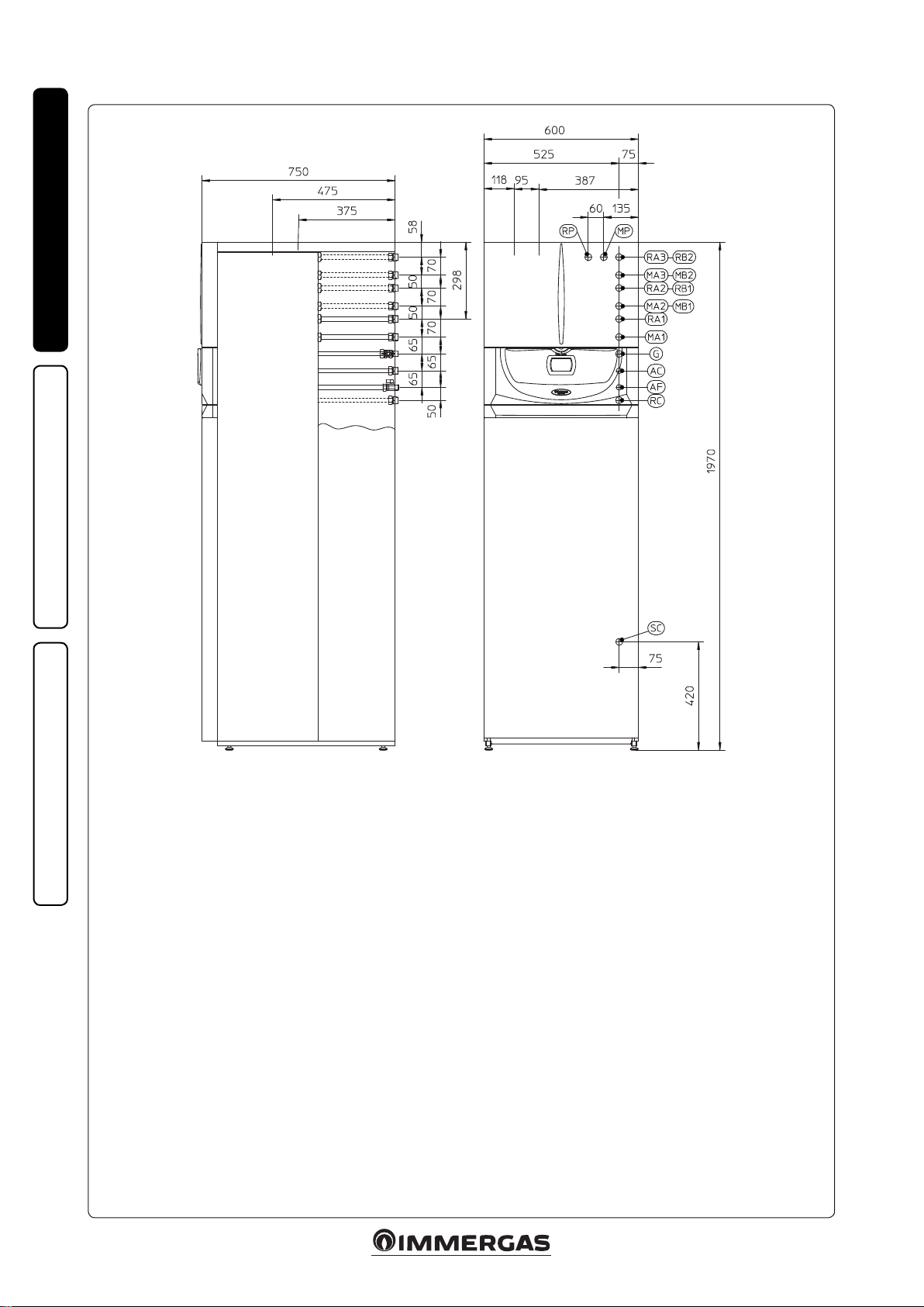
1.2 MAIN DIMENSIONS.
INSTALLERUSERMAINTENANCE TECHNICIAN
Key:
RP - Return to solar panels G 3/4”
MP - Flow from solar panels G 3/4”
RA3 - Zone 3 high temperature system return G 3/4” (optional)
MA3 - Zone 3 high temperature system ow G 3/4” (optional)
RA2 - Zone 2 high temperature system return G 3/4” (optional)
MA2 - Zone 2 high temperature system ow G 3/4” (optional)
RB2 - Zone 2 low temperature system return G 1” (optional)
MB2 - Zone 2 low temperature system ow G 1” (optional)
RB1 - Zone 1 low temperature system return G 1” (optional)
MB1 - Zone 1 low temperature system ow G 1” (optional)
RA1 - Zone 1 high temperature system return G 3/4”
MA1 - Zone 1 high temperature system ow G 3/4”
G - Gas supply G 1/2”
AC - DHW output G 3/4”
AF - DHW inlet G 3/4”
RC - Recirculation G 3/4” (optional)
SC - Condensate drain (min. internal diameter Ø 13 mm)
6
1-1
Page 7

1.3 GAS CONNECTION APPLIANCE
CATEGORY II
Our boilers are designed to operate with methane
gas (G20) and LPG. Supply pipes must be the
same as or larger than the 1/2”G boiler tting.
Before connecting the gas line, carefully clean
inside all the fuel feed system pipes to remove
any residue that could impair boiler eciency.
Also make sure the gas corresponds to that for
which the boiler is prepared (see boiler data
name plate). If different, the appliance must
be converted for operation with the other type
of gas (see converting appliance for other gas
types). e dynamic gas supply (methane or
LPG) pressure must also be checked according to the type used in the boiler, which must
comply with the technical standards in force, as
insucient levels can reduce generator output
and cause malfunctions. Ensure correct gas cock
connection. e gas supply pipe must be suitably
dimensioned according to current regulations
in order to guarantee correct gas ow rate to the
burner even in conditions of maximum generator output and to guarantee appliance eciency
(technical specications). e coupling system
must conform to technical standards in force.
Fuel gas quality. e appliance was designed
to operate with combustible gas free of impurities; otherwise it is advisable to t special lters
upstream of the appliance to restore the purity
of the fuel.
Storage tanks (in case of supply from LPG
depot).
- New LPG storage tanks may contain residual
inert gases (nitrogen) that degrade the mixture
delivered to the appliance casing functioning
anomalies.
- Due to the composition of the LPG mixture,
layering of the mixture components may occur
during the period of storage in the tanks. is
can cause a variation in the heating power of
the mixture delivered to the appliance, with
subsequent change in its performance.
2H3B/P
.
1.4 BOILER HYDRAULIC
CONNECTION.
Attention: in order not to void the condensa-
tion module warranty, before making the boiler
connections, carefully wash the heating system
(pipes, radiators, etc.) with special pickling or
descaling products to remove any deposits that
could compromise correct boiler operation.
A chemical treatment of the thermal system water is required, in compliance with the technical
standards in force, in order to protect the system
and the appliance from deposits (e.g., lime scale),
slurry or other hazardous deposits.
Water connections must be made in a rational
way using the couplings on the boiler template.
e boiler safety valves outlet must be connected
to a draining funnel. Otherwise, the manufacturer declines any responsibility in case of ooding
if the drain valve cuts in.
Attention: Immergas declines all liability in the
event of damage caused by the inclusion of automatic lling that is not its own brand.
In order to meet the system requirements established by the technical regulation in force in
relation to the pollution of drinking water, we
recommend installing the IMMERGAS antibackow kit to be used upstream of the cold
water inlet connection of the boiler. It is also
recommended that the heat transfer uid (e.g.
water + glycol) entered in the primary circuit
of the boiler (heating circuit), complies with the
local regulations in force.
Attention: to preserve the duration and the efciency features of the appliance, in the presence
of water whose features can lead to the deposit of
scale, installation of the “polyphosphate dispenser”
kit is recommended.
1.5 SOLAR CIRCUIT HYDRAULIC
CONNECTION.
Attention: when installing the solar circuit (pipes
and ttings), only use suitable materials that
withstand high temperatures.
e pump unit allows you to connect the storage
tank to the solar collector, making the water circulate according to the request of the control unit.
N.B.: the pipes for connection to the solar col-
lector must be ordered separately.
- Every time the solar system is emptied, the
system must be rinsed well with running water.
- e circulation unit is not designed for use in
direct contact with swimming pool water.
Condensate drain. To drain the condensate
produced by the appliance, it is necessary to
connect to the drainage system by means of acid
condensate resistant pipes, with an internal Ø of
at least 13 mm. e system connecting the appliance to the drainage system must be carried out
in such a way as to prevent freezing of the liquid
contained in it. Before appliance ignition, ensure
that the condensate can be correctly removed.
Aer rst ignition, check that the drain trap is
lled with condensate (para. 1.21). Also, comply
with national and local regulations on discharging waste waters.
INSTALLERUSERMAINTENANCE TECHNICIAN
7
Page 8
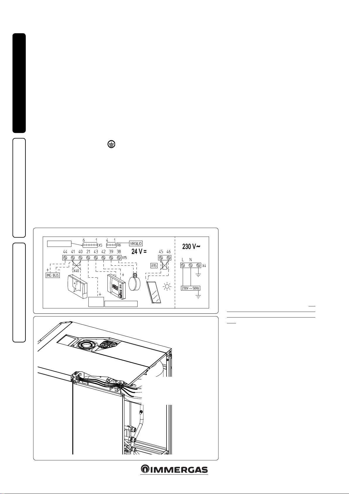
CAVO COMANDO REMOTO
1.6 ELECTRICAL CONNECTION.
e “Hercules Solar 26 2 ErP” boiler has an
IPX5D protection rating for the entire appliance.
Electrical safety of the appliance is reached only
when it is correctly connected to an ecient
earthing system as specied by current safety
standards.
Attention: Immergas S.p.A. disclaims any liability for damage or physical injury caused
by failure to connect the boiler to an ecient
earthing system or failure to comply with the
reference standards.
INSTALLERUSERMAINTENANCE TECHNICIAN
Also ensure that the electrical installation corresponds to maximum absorbed power specications as shown on the boiler data nameplate.
Boilers are supplied complete with an “X” type
power cable without plug.
e power supply cable must be connected to
a 230V ±10% / 50Hz mains supply respecting
L-N polarity and the earth connection
this network must also feature a multi-pole
circuit breaker of class III overvoltage category.
When replacing the power supply cable, contact
a qualied rm (e.g. the Authorised Aer-Sales
Technical Assistance Service).
e power cable must be laid as shown (Fig. 1-3).
In the event of mains fuse replacement on the
P.C.B., use a 3.15A quick-blow fuse. For the main
power supply to the appliance, never use adapters, multiple sockets or extension leads.
Relay (Optional)
DIM (Op-
tional)
Solar panels electrical connection. Only use an
appropriately sized cable to make the connections. Making them follow the same route as the
power supply cable (in the relevant pipe), make
the connections on the control panel on clamps
45 and 46, eliminating the resistance R15 (Fig.
1-2). Connect the supplied probe on the solar
panel and position it in the relevant seat.
Installation with system operating at direct
low temperature. e boiler can directly feed a
low temperature system by acting on parameter
“P66” (Par. 3.8) and setting the delivery temperature adjustment range “P66/A” and “P66/B”. In
this situation it is good practice to insert a safety
device in series with the power supply and boiler.
is device is made up from a thermostat with
a temperature limit of 60°C. e thermostat
must be positioned on the system ow pipe at
a distance of at least 2 metres from the boiler.
on
1.7 REMOTE CONTROLS AND ROOM
CHRONOTHERMOSTATS
OPTIONAL.
The boiler is prepared for the application of
room chrono-thermostats or remote controls,
which are available as optional kits. All Immergas
chrono-thermostats are connected with 2 wires
only. Carefully read the user and assembly instructions contained in the accessory kit.
• On/O digital Immergas chrono-thermostat
(Fig. 1-3). e chrono-thermostat allows:
Super CAR (Optional)
CAVO ALIMENTAZIONE
POWER SUPPLY CABLE
CAVO SONDA SOLARE
SOLAR PROBE CABLE
REMOTE CONTROL CABLE
- set two room temperature value: one for
daytime (comfort temperature) and one for
night-time (reduced temperature);
- set a weekly program with four daily switch
on and switch o times;
- select the required operating mode from the
various possible alternatives:
- manual mode (with adjustable temperature).
- automatic mode (with set program).
- forced automatic mode (momentarily
changing the temperature of the automatic
program).
e chrono-thermostat is powered by two 1.5V
LR 6 type alkaline batteries.
• ere are two types of remote controls availa-
ble: Comando Amico Remoto remote controlV2
V2
) (Fig. 1-4) and Super Comando Amico
(CAR
Remoto remote control (Super CAR) (Fig. 1-5)
both with a climate chrono-thermostat operation. In addition to the functions described in
the previous point, the chrono-thermostat
panels enable the user to control all the important information regarding operation of
the appliance and the central heating system
with the opportunity of easily intervening on
the previously set parameters without having to
go to the place where the appliance is installed.
e panel is provided with self-diagnosis to
display any boiler functioning anomalies.
e climate chrono-thermostat incorporated
into the remote panel enables the system ow
temperature to be adjusted to the actual needs
1-2
of the room being heated, in order to obtain
the desired room temperature with extreme
precision and therefore with evident saving in
running costs. e chrono-thermostat is fed
directly by the boiler by means of the same 2
wires used for transmitting data between boiler
and device.
Important: if the system is subdivided into areas
using the relevant kit, the CAR
CAR must be used with its climate thermostat
function disabled, i.e. it must be set to On/O
mode.
V2
CAR
, Super CAR or On/O chrono-ther-
mostat electrical connection (Optional). e
operations described below must be performed
aer having removed the voltage from the appli-
1-3
ance. Any On/O room chrono-thermostat must
be connected to clamps 40 and 41 eliminating
jumper X40 (Fig. 3-2). Make sure that the On/
O thermostat contact is of the “clean” type, i.e.
independent of the mains voltage, otherwise the
P.C.B. would be damaged. Any CAR V2 or Super
CAR must be connected by means of terminals
IN+ and IN- to terminals 42 and 43 on the
P.C.B. (in the boiler), eliminating jumper X40
and respecting polarity (Fig. 3-2). Connection
with the wrong polarity prevents functioning, but
without damaging the CARV2 e boiler can only
be connected to one remote control.
Important: if the Comando Amico Remoto
remote control
V2
is used, arrange two separate
lines in compliance with current regulations
regarding electrical systems. No boiler pipes
must ever be used to earth the electric system or
telephone lines. Ensure elimination of this risk
before making the boiler electrical connections.
V2
and the Super
8
Page 9
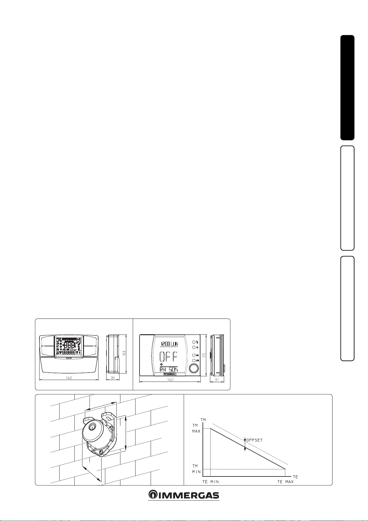
1.8 EXTERNAL TEMPERATURE PROBE
OPTIONAL.
e boiler is designed for the application of the
external temperature probe (Fig. 1-6), which is
available as an optional kit. Refer to the relative
instruction sheet to position the external probe.
e probe can be connected directly to the boiler
electrical system and allows the max. system
ow temperature to be automatically decreased
when the external temperature increases, in
order to adjust the heat supplied to the system
according to the change in external temperature. e external probe always operates when
connected, regardless of the presence or type of
room chrono-thermostat used and can work in
combination with Immergas timer thermostats.
e correlation between system ow temperature
and external temperature is determined by the
parameters set in menu “M5” under item “P66”
according to the curves represented in the diagram (Fig. 1-7). e electric connection of the
external probe must be made on clamps 38 and
39 on the boiler P.C.B. (Fig. 3-2).
INSTALLERUSERMAINTENANCE TECHNICIAN
Comando Amico Remoto remote control
On/O digital chrono-thermostat.
45
31
V2
(CARV2)
1-4 1-5
Super Comando Amico Remoto remote control
(Super CAR)
Correction law of the ow temperature depending on the external tem-
perature and user adjustment of the central heating temperature.
58
1-6
EXTERNAL PROBE
TM-MAX/MIN = Selected ow
temp. range.
TE = External temperature.
1-7
9
Page 10

1.9 IMMERGAS FLUE SYSTEMS.
Immergas supplies various solutions separately
from the boilers regarding the installation of
air intake terminals and ue exhaust, which are
fundamental for boiler operation.
Attention: the boiler must be installed exclusively with an original Immergas “Green
Range” inspectionable air intake device and
fumes extraction system made of plastic, as
required by the regulations in force.
e plastic pipes cannot be installed outdoors,
INSTALLERUSERMAINTENANCE TECHNICIAN
for tracts longer than 40 cm, without suitable
protection from UV rays and other atmospheric agents.
is system can be identied by an identication mark and special distinctive marking
bearing the note: “only for condensing boilers”.
• Resistance factors and equivalent lengths. Each
ue component has a Resistance Factor based
on experimental tests and specied in the table
below. e Resistance Factor for individual
components is independent from the type of
boiler on which it is installed and has a dimensionless size. It is however, conditioned by the
temperature of the uids that pass through the
pipe and therefore, varies according to applications for air intake or ue exhaust. Each single
component has a resistance corresponding to
a certain length in metres of pipe of the same
diameter; the so-called equivalent length,
can be obtained from the ratio between the
relative Resistance Factors. All boilers have an
experimentally obtainable maximum Resistance
Factor equal to 100. e maximum Resistance
Factor allowed corresponds to the resistance
encountered with the maximum allowed pipe
length for each type of Terminal Kit. This
information allows calculations to be made to
verify the possibility of setting up various ue
congurations.
• Positioning the gaskets (black) for “green
range” ue systems. Position the gasket correctly (for bends and extensions) (Fig. 1-8):
- gasket (A) with notches, to use for bends;
- gasket (B) without notches, to use for exten-
sions;
N.B.: if component lubrication (already car-
ried out by the manufacturer) is not sucient,
remove the residual lubricant using a dry cloth,
then to ease tting coat the parts with talc, supplied in the kit.
• Coupling extension pipes and concentric
elbows. To install push-tting extensions with
other elements of the ue, proceed as follows:
Install the concentric pipe or elbow with the
male side (smooth) on the female side (with lip
seal) to the end stop on the previously installed
element in order to ensure sealing eciency of
the coupling.
Attention: if the exhaust terminal and/or
concentric extension pipe needs shortening,
consider that the internal duct must always
protrude by 5 mm with respect to the external
duct.
• N.B.: for safety purposes, do not obstruct the
boiler intake/exhaust terminal, even temporaril y.
• N.B.: when installing horizontal pipes, a mini-
mum inclination of 3% must be maintained and
a section clip with pin must be installed every
3 metres.
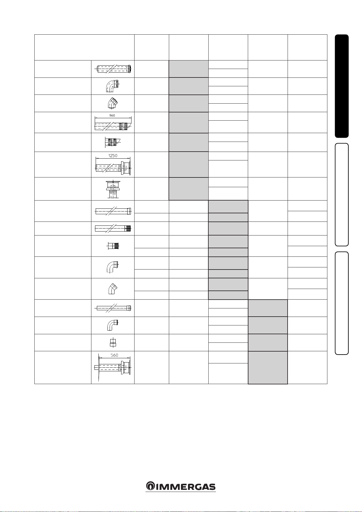
1.10 TABLES OF RESISTANCE FACTORS
AND EQUIVALENT LENGTHS.
TYPE OF DUCT
Concentric pipe Ø 80/125 m 1
Concentric bend 90° Ø 80/125
Concentric bend 45° Ø 80/125
Terminal complete with concentric
horizontal intake-exhaust Ø 80/125
1-8
Resistance
Factor
(R)
2.1
3.0
2.1
2.8
(A)
(B)
Equivalent length
in m of concentric
pipe Ø 80/125
1
1.4
1
1.3
Terminal complete with concentric
vertical intake-exhaust Ø 80/125
Concentric bend 90° Ø 80/125 with
inspection
Stub pipe with inspection Ø 80/125
10
3.6
3.4
3.4
1.7
1.6
1.6
Page 11
TYPE OF DUCT
Resistance
Factor
(R)
Equivalent length
in m of concentric
pipe Ø 60/100
Equivalent length
in metres of pipe
Ø 80
Equivalent length
in metres of pipe
Ø 60
Equivalent length
in m of concentric
pipe Ø 80/125
Concentric pipe Ø 60/100
m 1
Concentric bend 90° Ø
60/100
Concentric bend 45° Ø
60/100
Terminal complete with
concentric horizontal
intake-exhaust Ø 60/100
Concentric horizontal
intake- exhaust terminal
Ø 60/100
Terminal complete with
concentric vertical intakeexhaust Ø 60/100
Concentric vertical intakeexhaust terminal Ø 60/100
Pipe Ø 80 m 1
Complete intake terminal
Ø 80 m 1
Intake terminal Ø 80
Exhaust terminal Ø 80
Bend 90° Ø 80
Bend 45° Ø 80
Pipe Ø 60 m 1 for ducting
Bend 90° Ø 60 for ducting
Reduction Ø 80/60
Intake and
Exhaust 6.4
Intake and
Exhaust 8.2
Intake and
Exhaust 6.4
Intake and
Exhaust 15
Intake and
Exhaust 10
Intake and
Exhaust 16.3
Intake and
Exhaust 9
Intake 0.87 m 0.1 Intake m 1.0
Exhaust 1.2 m 0.2 Exhaust m 1.0
Intake 3 m 0.5 Intake m 3.4 Exhaust m 0.9 m 1.4
Intake 2.2 m 0.35 Intake m 2.5
Exhaust 1.9 m 0.3 Exhaust m 1.6
Intake 1.9 m 0.3 Intake m 2.2
Exhaust 2.6 m 0.4 Exhaust m 2.1
Intake 1.2 m 0.2 Intake m 1.4
Exhaust 1.6 m 0.25 Exhaust m 1.3
Exhaust 3.3 m 0.5
Exhaust 3.5 m 0.55
Intake and
Exhaust 2.6
m 1
m 1.3
m 1
m 2.3
m 1.5
m 2.5
m 1.4
m 0.4
Intake m 7.3
Exhaust m 5.3
Intake m 9.4
Exhaust m 6.8
Intake m 7.3
Exhaust m 5.3
Intake m 17.2
Exhaust m 12.5
Intake m 11.5
Exhaust m 8.3
Intake m 18.7
Exhaust m 13.6
Intake m 10.3
Exhaust m 7.5
Intake 3.8
Exhaust 2.7
Intake 4.0
Exhaust 2.9
Intake m 3.0
Exhaust m 2.1
Exhaust m 1.9 m 3.0
Exhaust m 2.5 m 3.9
Exhaust m 1.9 m 3.0
Exhaust m 4.5 m 7.1
Exhaust m 3.0 m 4.7
Exhaust m 4.9 m 7.7
Exhaust m 2.7 m 4.3
Exhaust m 0.4
Exhaust m 0.6
Exhaust m 0.8
Exhaust m 0.5
Exhaust m 1.0 m 1.5
Exhaust m 1.1 m 1.6
Exhaust m 0.8 m 1.2
INSTALLERUSERMAINTENANCE TECHNICIAN
m 0.4
m 0.5
m 1
m 0.9
m 0.9
m 1.2
m 0.5
0.7
Terminal complete with
exhaust
vertical Ø 60 for ducting
Exhaust 12.2 m 1.9
11
Intake m 14
Exhaust m 3.7 m 5.8
Exhaust m 10.1
Page 12
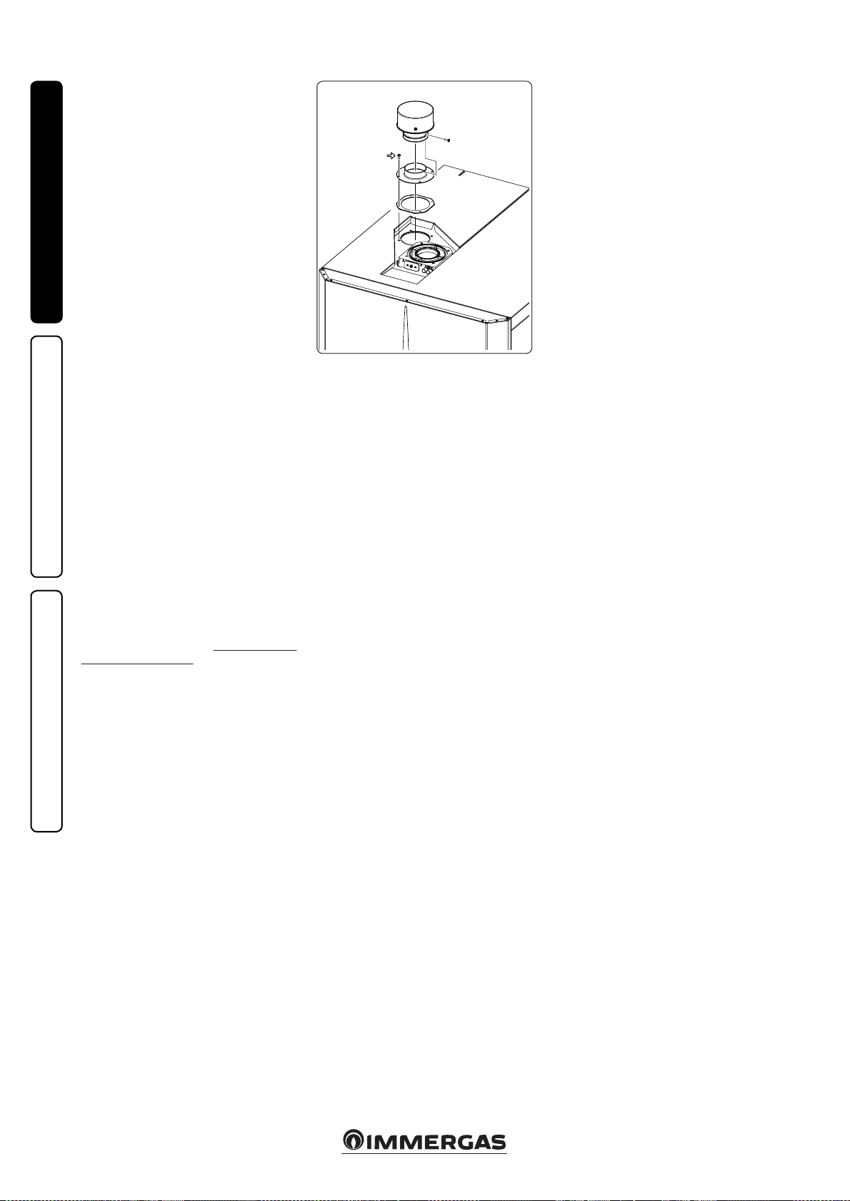
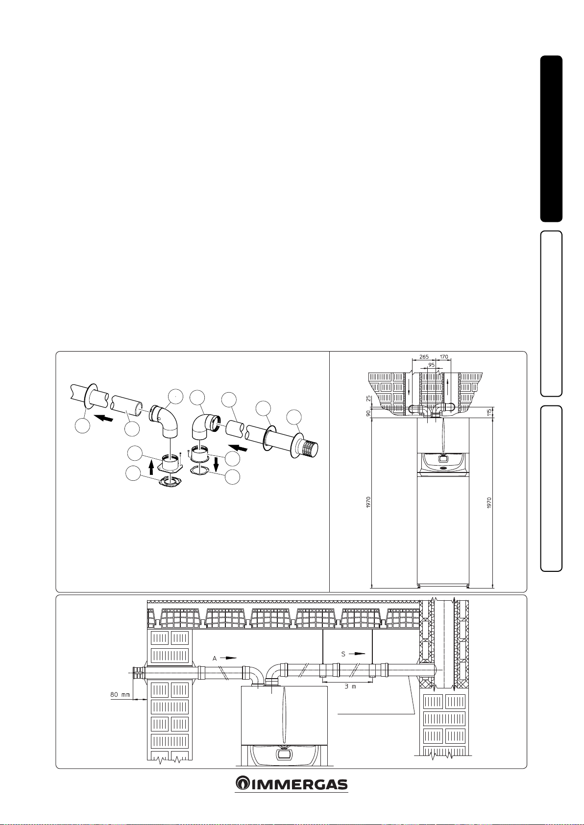
1.11 INSTALLATION OF BOILER TYPE B
WITH OPEN CHAMBER AND FAN
ASSISTED OPTIONAL.
In this conguration the relevant terminal must
be used (present in the intake kit for the installation in question) to be placed on the intake hole
above the sealed chamber (Fig. 1-8). Air intake
takes place directly from the environment and
ue exhaust in individual chimney or to the outside. e boiler in this conguration, following
the assembly instructions stated on the relative
instruction sheet, is classied as type B
INSTALLERUSERMAINTENANCE TECHNICIAN
(according to the applicable regulations).
With this conguration:
air intake takes place directly from the environ-
ment in which the boiler is installed and only
functions in permanently ventilated rooms
- the ue gas exhaust must be connected to its
own individual ue or ducted directly into the
external atmosphere;
- Type B open chamber boilers must not be
installed in places where commercial, artisan
or industrial activities take place, which use
products that may develop volatile vapours
or substances (e.g. acid vapours, glues, paints,
solvents, combustibles, etc.), as well as dusts
(e.g. dust deriving from the processing of
wood, coal dust, cement, etc.), which may be
harmful for the components of the appliance
and jeopardise operation;
- in B23 and B53 conguration, the boilers must
not be installed in bedrooms, bathrooms or in
studio ats;
- installation of appliances in B23 or B53 congura-
tion is recommended in non-residential premises and which are permanently ventilated.
The technical regulations in force must be
respected.
Max. length of exhaust duct. e ue pipe (both
vertical or horizontal) can be extended to a max.
length of 30 linear metres.
or B53
23
1-9
X4
12
Page 13
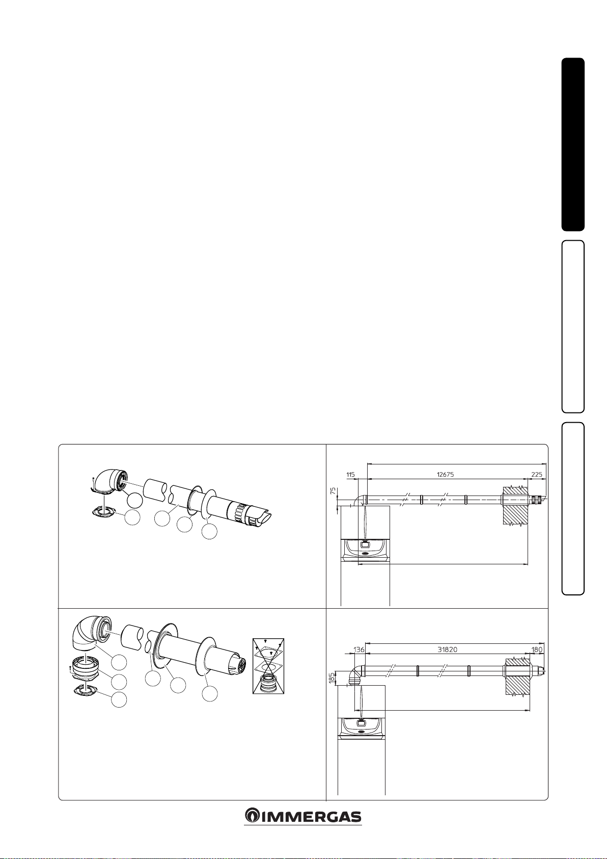
1.12 CONCENTRIC HORIZONTAL KIT
INSTALLATION.
Type C configuration, sealed chamber and
fan assisted.
e installation of this terminal is governed by
the applicable technical standards and subsequent amendments, that enables wall ue exhaust
for condensing boilers with low NOx in the cases
provided. e position of the terminal (in terms
of distances from openings, overlooking buildings, oor, etc.) must be in compliance with the
regulations in force.
is terminal is connected directly to the outside
of the building for air intake and ue exhaust. e
horizontal kit can be installed with the rear, right
side, le side or front outlet. For installation with
frontal outlet, one must use the xing plate and
a concentric bend coupling in order to ensure
sucient space to carry out the tests required
by law upon commissioning.
• External grid. Both the Ø 60/100 and Ø 80/125
intake/exhaust terminal, if properly installed, is
pleasant to look at on the outside of the building. Make sure that the external silicone wall
sealing plate is properly inserted in the wall.
N.B.: for proper system operation the terminal
with grid must be installed correctly ensuring
that, the "high" indication on the terminal is
observed during installation.
Horizontal intake-exhaust kit Ø 60/100 Kit
assembly (Fig. 1-10): install the bend with ange
(2) on the central hole of the boiler, positioning
gasket (1) with the circular projections downwards in contact with the boiler flange, and
tighten using the screws supplied with the kit. Fit
the Ø 60/100 (3) concentric terminal pipe with
the male side (smooth) to the female side of the
bend (2) up to the end stop; making sure that the
internal and external wall sealing plate have been
tted, this will ensure sealing and joining of the
elements making up the kit.
• Extensions for Ø 60/100 horizontal kit (Fig.
1-11). e kit with this conguration can be
extended up to a max. 12.9 horizontal m in-
cluding the terminal with grid and excluding
the concentric bend leaving the boiler. is
conguration corresponds to a resistance factor
of 100. In this case the special extensions must
be requested.
Immergas also provides a Ø 60/100 simplied
terminal, which in combination with its extension kits allows you to reach a maximum extension of 11.9 metres.
Horizontal intake-exhaust kit Ø 80/125 Kit
assembly (Fig. 1-12): to install the kit Ø 80/125
one must use the anged adapter kit in order
to install the ue system Ø 80/125. Install the
anged adaptor (2) on the central hole of the
boiler, positioning gasket (1) with the circular
projections downwards in contact with the boiler
ange and tighten using the screws supplied with
the kit. Engage the bend (3) with the male side
(smooth) to the end stop on the adapter (1). Fit
the Ø 80/125 (5) concentric terminal pipe with
the male side (smooth) to the female side of the
bend (4) (with lip seals) up to the end top; making
sure that the internal (6) and external wall sealing
plate (7) have been tted, this will ensure sealing
and joining of the elements making up the kit.
• Extensions for horizontal kit Ø 80/125 (Fig.
1-13). e kit with this conguration can be
extended up to a max. length of 32 m, including the terminal with grid and excluding the
concentric bend leaving the boiler. If additional components are assembled, the length
equivalent to the maximum allowed must be
subtracted. In this case the special extensions
must be requested.
INSTALLERUSERMAINTENANCE TECHNICIAN
2
1
3
4
e kit includes:
N° 1 - Gasket (1)
N° 1 - Concentric bend Ø 60/100 (2)
N° 1 - Int./exhaust concentric terminal Ø 60/100 (3)
N° 1 - Internal wall sealing plate (4)
N° 1 - External wall sealing plate (5)
5
3
2
1
e adaptor kit includes:
N° 1 - Gasket (1)
N° 1 - Adaptor Ø 80/125 (2)
1-12
4
5
6
e Kit Ø 80/125 includes:
N° 1 - Concentric bend Ø 80/125 a 87° (3)
N° 1 - Int./exhaust concentric terminal Ø
80/125 (4)
N° 1 - Internal wall sealing plate (5)
N° 1 - External wall sealing plate (6)
e remaining kit components must not be
used
C
13
C
13
Max 12900 mm
Max 12790 mm
Max 32000 mm
Max 31956 mm
C
13
1-111-10
C
13
1-13
13
Page 14
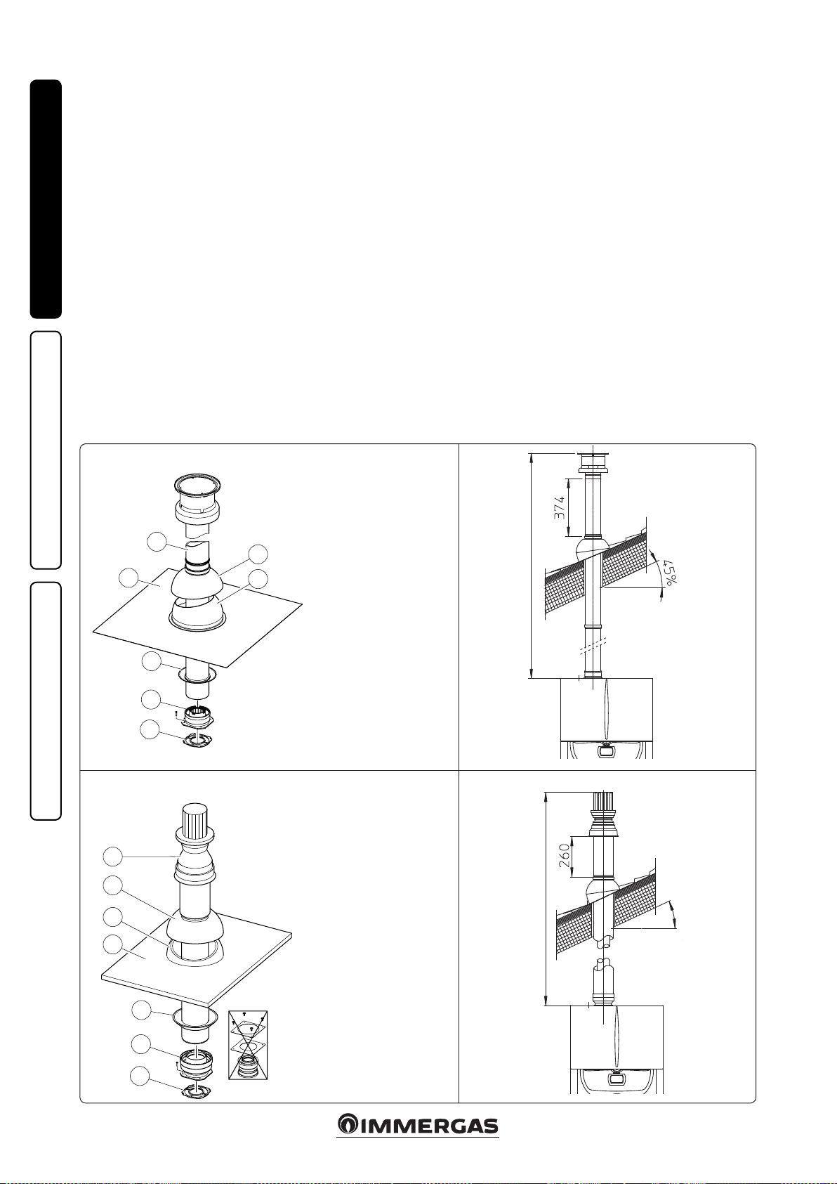
1.13 CONCENTRIC VERTICAL KIT
INSTALLATION.
Type C configuration, sealed chamber and
fan assisted.
Concentric vertical intake and exhaust kit. is
vertical terminal is connected directly to the outside of the building for air intake and ue exhaust.
N.B.: the vertical kit with aluminium tile enables
installation on terraces and roofs with a maximum slope of 45% (approx 25°) and the height
between the terminal cap and half-shell (374 mm
INSTALLERUSERMAINTENANCE TECHNICIAN
for Ø 60/100 and 260 mm for Ø 80/125) must
always be observed.
Vertical kit with aluminium tile Ø 60/100.
Kit assembly (Fig. 1-14): install the concentric
ange (2) on the central hole of the boiler, positioning gasket (1) with the circular projections
downwards in contact with the boiler ange, and
tighten using the screws supplied with the kit.
Installation of the fake aluminium tile: replace
the tiles with the aluminium sheet (4), shaping
it to ensure that rainwater runs o. Position the
xed half-shell (6) on the aluminium tile and insert the intake-exhaust pipe (5). Fit the Ø 60/100
(3) concentric terminal pipe with the male end
(5) (smooth) into the ange (2) up to the stop;
making sure that the wall sealing plate has been
tted (3), this will ensure sealing and joining of
the elements making up the kit.
Note: when the boiler is installed in areas where
very rigid temperatures can be reached, a special
anti-freeze kit is available that can be installed as
an alternative to the standard kit.
• Extensions for vertical kit Ø 60/100 (Fig. 1-15).
e kit with this conguration can be extended
to a max. straight vertical length of 14.4 m,
including the terminal. This configuration
corresponds to a resistance factor of 100. In
this case specic extensions must be requested.
Vertical kit with aluminium tile Ø 80/125.
Kit assembly (Fig. 1-16): to install the kit Ø
80/125 one must use the anged adapter kit in
order to install the ue system Ø 80/125. Install
the anged adaptor (2) on the central hole of the
boiler, positioning gasket (1) with the circular
projections downwards in contact with the boiler
ange and tighten using the screws supplied
with the kit. Installation of the fake aluminium
tile: replace the tiles with the aluminium sheet
(4), shaping it to ensure that rainwater runs o.
Position the xed half-shell (5) on the aluminium
tile and insert the intake-exhaust pipe (7). Fit the
Ø 80/125 concentric terminal pipe with the male
side (smooth) to the female side of the adapter (1)
(with lip gaskets) up to the end stop; making sure
that the wall sealing plate (3) has been tted, this
will ensure sealing and joining of the elements
making up the kit.
• Extensions for vertical kit Ø 80/125 (Fig. 1-17).
e kit with this conguration can be extended
up to a max. length of 32 m including the terminal. If additional components are assembled,
the length equivalent to the maximum allowed
must be subtracted. In this case specic extensions must be requested.
1-14
1-16
C
5
4
3
2
1
7
6
e Kit includes:
N° 1 - Gasket (1)
N° 1 - Female concentric ange (2)
N° 1 - Wall sealing plate (3)
N° 1 - Aluminium tile (4)
N° 1 - Int./exhaust concentric pipe Ø
60/100 (5)
N° 1 - Fixed half-shell (6)
N° 1 - Mobile half-shell (7)
C
e adaptor kit includes:
7
6
5
4
3
N° 1 - Gasket (1)
N° 1 - Adaptor Ø 80/125 (2)
e Kit Ø 80/125 includes:
N° 1 - Wall sealing plate (3)
N° 1 - Aluminium tile (4)
N° 1 - Fixed half-shell (5)
N° 1 - Mobile half-shell (6)
N° 1 - Int./exhaust concentric
pipe Ø 80/125 (7)
e remaining kit components
must not be used
1-15
33
Max 14400 mm
1-17
33
Max 32000 mm
Max 45%
C
33
C
33
2
1
14
Page 15
1.14 SEPARATOR KIT INSTALLATION.
Type C configuration, sealed chamber and
fan assisted.
Separator kit Ø 80/80. is kit allows air to come
in from outside the building and the fumes to exit
from the chimney or ue through divided ue
exhaust and air intake pipes. Combustion products are expelled from pipe (S) (in plastic, so as
to resist acid condensate). Air is taken in through
duct (A) for combustion (this is also in plastic).
e intake pipe (A) can be installed either on the
right or le hand side of the central exhaust pipe
(S). Both ducts can be routed in any direction.
• Kit assembly (Fig. 1-18): install ange (4) on
the central hole of the boiler, positioning gasket
(1) with the circular projections downwards in
contact with the boiler ange, and tighten using
the hex screws with at tip supplied with the
kit. Remove the at ange present in the most
external hole and replace it with the ange (3),
positioning the gasket (2) already present in
the boiler and tighten using the supplied selfthreading screws. Fit the male side (smooth) to
the bends (5) in the female side of the anges
(3 and 4). Fit the intake terminal (6) with the
male side (smooth) in the female side of the
bend (5) up to the end stop, ensuring that the
internal and external wall sealing plates are
tted. Fit the exhaust pipe (9) with the male
side (smooth) to the female side of the bend
(5) up to the end stop; making sure that the
internal wall sealing plate has been tted, this
will ensure sealing and joining of the elements
making up the kit.
• Installation clearances (Fig. 1-19). e minimum installation clearance measurements of
the Ø 80/80 separator terminal kit have been
stated in some limit conditions.
• Extensions for separator kit Ø 80/80. The
maximum vertical straight length (without
bends) that can be used for Ø 80 intake and
exhaust pipes is 41 metres, regardless from
whether they are used for intake or exhaust.
e maximum horizontal straight length (with
bend in suction and in exhaust) that can be
used for Ø 80 intake and exhaust pipes is 36
metres, regardless from whether they are used
for intake or exhaust.
N.B.: to favour the removal of possible condensate forming in the exhaust pipe, tilt the pipes
towards the boiler with a minimum slope of
1.5% (Fig. 1-20).
INSTALLERUSERMAINTENANCE TECHNICIAN
1-18
5
5
6
C53* - C
7
nal.
S
9
4
1
N° 2 - Bend 90° Ø 80 (5)
N° 1 - Intake terminal Ø 80 (6)
N° 2 - Internal wall sealing plates (7)
N° 1 - External wall sealing plate (8)
N° 1 - Drain pipe Ø 80 (9)
A
3
2
7
e kit includes:
N° 1 - Exhaust gasket (1)
N° 1 - Flange seal gasket (2)
N° 1 - Female intake ange (3)
N° 1 - Female drain ange (4)
* to er complete C53 conguration also provide for a roof discharge termi-
1-19
83
C
43
8
C
83
15
Minimum slope 1.5 %
1-20
Page 16
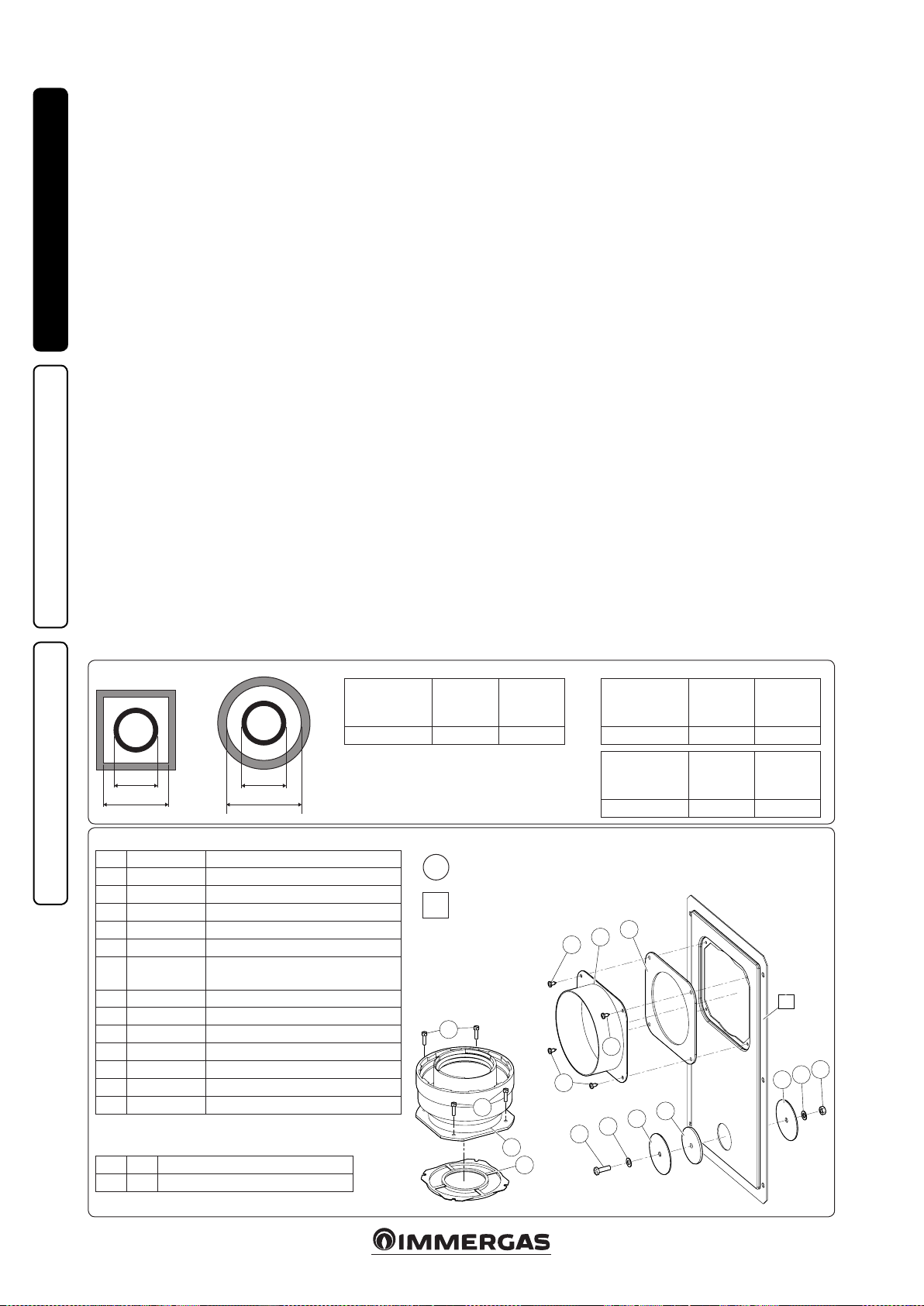
1.15 ADAPTOR C9 KIT INSTALLATION.
is kit allows an Immergas boiler to be installed
in "C
" conguration, with combustion air intake
93
directly from the sha where the ue gas exhaust
is, obtained by means of a ducting system.
System composition.
e system must be combined with the following
components (sold separately) to be functional
and complete:
- kit C93 Ø 100 or Ø125 version
- ducting kit Ø 60 or Ø 80
INSTALLERUSERMAINTENANCE TECHNICIAN
- fumes exhaust kit Ø 60/100 or Ø 80/125 congured according to the installation and type
of boiler.
Kit Assembly.
- Mount the components of kit "C9" on the door
(A) of the ducting system (Fig. 1-22).
- (Version Ø 125 only) mount the anged adaptor (11) interposing the concentric gasket (10)
on the boiler, tting it with the screws (12).
- Mount the ducting system as described in the
relative instructions sheet.
- Calculate the distances between the boiler drain
and the bend of the ducting system.
- Prepare the boiler ue system, making sure that
the internal pipe of the concentric kit is tted
properly in the bend of the ducting system
(quota "X" g. 1-23), while the external pipe
must be tted on the adaptor until it stops (1).
N.B.: to encourage the removal of possible
condensate forming in the exhaust pipe, tilt
the pipes towards the boiler with a minimum
slope of 1.5%.
- Mount the cover (A) complete with adaptor (1)
and caps (6) on the wall and assemble the ue
system to the ducting system.
N.B.: (version Ø 125 only) before assembly
check the gaskets are in the right position. In
the event component lubrication (already carried out by the manufacturer) is not sucient,
remove the residual lubricant using a dry cloth,
then to ease tting coat the parts with common
or industrial talc.
Once all components have been assembled properly, the exhaust fumes will be expelled via the
ducting system; the combustion air for normal
boiler operation will be aspirated directly by the
sha (Fig. 1-23).
Technical data.
- e dimensions of the shas must ensure a
minimum gap between the outer wall of the
smoke duct and the inner wall of the sha: 30
mm for circular section shas and 20 mm in
the event of a square section sha (Fig. 1-21).
- Maximum 2 changes of direction are allowed
on the vertical section of the ue system with
a maximum clearance angle of 30° with respect
to the vertical.
- e maximum vertical extension using a Ø 60
ducting system is 13 m, the maximum extension includes 1 bend Ø 60/10 at 90°, 1 m of
horizontal pipe 60/100, 1 90° ducted bend Ø
60 and the roof terminal for ducting.
To determine the C93 ue system in congu-
rations other than that described (Fig. 1-23)
one must consider that 1 metre of ducted pipe
according to the indications described has a
resistance factor equal to 4.9.
- e maximum vertical extension using a Ø 80
ducting system is 28 m, the maximum extension includes 1 adapter 60/100 to 80/125, 1 87°
bend Ø 80/125, 1 m of horizontal pipe 80/125,
1 90° ducted bend Ø 80 and the roof terminal
for ducting.
To determine the C93 ue system in congura-
tions other than that described (Fig. 1-23) one
must consider the following pressure drops:
- 1 m of concentric pipe Ø 80/125 = 1 m of
ducted pipe;
- 1 87° bend = 1.4 m of ducted pipe;
Consequently one must subtract the equivalent
length of the part added to the 28 m available.
1-21
A
B
Kit composition:
Ref. Qty Description
1 1 Door adaptor Ø 100 or Ø 125
2 1 Door gasket made of neoprene
3 4 Screws 4.2 x 9 AF
4 1 Hex headed screw M6 x 20
5 1 Flat nylon washer M6
6 2 Door hole closure metal-sheet plate
plug
7 1 Plug gasket made of neoprene
8 1 Toothed washer M6
9 1 Nut M6
10 1 (kit 80/125) Concentric gasket Ø 60-100
11 1 (kit 80/125) Flanged adapter Ø 80-125)
12 4 (kit 80/125) Hex headed screws M4 x 16 slotted
- 1 (kit 80/125) Bag of lubricating talc
Supplied separately:
Ref. Qty Description
A 1 Ducting kit door
A
C
Rigid Ø 60
ducting (A)
mm
66 106 126
SHAFT
(B) mm
Installation drawings key:
Unique identication of the component in
1
the kit
Identication of the component not supplied
in this kit
A
12
12
SHAFT
(C) mm
11
10
Rigid Ø 80
ducting (A)
mm
86 126 146
Flexible Ø 80
ducting (A)
mm
90 130 150
2
1
3
3
3
6
5
4
SHAFT
(B) mm
SHAFT
(B) mm
7
SHAFT
(C) mm
SHAFT
(C) mm
A
6
8
1-22
9
16
Page 17

C
93
X
C
53
INSTALLERUSERMAINTENANCE TECHNICIAN
1.16 DUCTING OF FLUES OR
TECHNICAL SLOTS.
Ducting is an operation through which, via
the introduction of one or more relevant pipes,
one achieves a system for the evacuation of the
combustion products of a gas appliance, made up
from the coupling of an existing or new ducting
pipe with a chimney, ue or technical slot (also
in new buildings) (Fig. 1-24). Ducting requires
ducts declared to be suitable for the purpose by
the manufacturer, following the installation and
user instructions, provided by the manufacturer
and the requirements of the standards in force.
Immergas ducting system. e Ø 60 rigid and Ø
80 exible “Green Range” ducting systems must
only be used for domestic use and with Immergas
condensing boilers.
In any case, ducting operations must respect
the provisions contained in the standard and in
current technical regulations; in particular, the
declaration of conformity must be compiled at
the end of work and on commissioning of the
ducted system. e instructions in the project
or technical report must likewise be followed, in
cases provided for by the standard and current
technical regulations. e system or components
of the system have a technical life complying with
current standards, provided that:
- it is used in average atmospheric and environ-
mental conditions, according to current regulations (absence of fumes, dusts or gases that can
alter the normal thermophysical or chemical
conditions; existence of temperatures coming
within the standard range of daily variation,
etc.).
- Installation and maintenance must be per-
formed according to the indications supplied
by the manufacturer and in compliance with
the provisions in force.
- e max. possible length of the Ø 60 exible
ducting vertical section is equal to 22 m. is
length is obtained considering the complete
Ø 80 exhaust terminal, 1m of Ø 80 pipe in
exhaust, two 90° Ø 80 bends at boiler outlet.
1-23
- e max. possible length of the Ø 80 exible
ducting vertical section is equal to 30 m. is
length is obtained considering the complete
exhaust terminal, 1m of Ø 80 pipe in exhaust,
two 90° Ø 80 bends at boiler outlet for connecting to the ducting system and two direction
changes of the exible hose inside the chimney/
technical slot.
- e maximum possible length of the Ø 80 rigid
ducting vertical section is equal to 30 m. is
length is obtained considering the complete
Ø 80 exhaust terminal, 1m of Ø 80 pipe in exhaust, two 90° Ø 80 bends on the boiler outlet.
1.17 CONFIGURATION TYPE B, OPEN
CHAMBER AND FAN ASSISTED FOR
INDOORS.
e appliance can be installed inside buildings
in
or B53 mode; in this case, all technical rules
23
and national and local regulations in force, must
be complied with.
For installation the suitable kit must be used,
referred to in paragraph 1.11.
1-24
1.18 FLUE GAS EXHAUST TO FLUE/
CHIMNEY.
e ue exhaust does not necessarily have to be
connected to a branched type traditional ue.
e ue exhaust, for boiler clots installed in C
configuration, can be connected to a special
LAS type multiple ue. For B23 congurations,
exhaust is only allowed into individual chimney
or directly into the external atmosphere via a
relevant terminal. e multiple ues and the
combined ues must also only be connected to
type C appliances of the same type (condensing),
having nominal heat inputs that do not dier by
more than 30% less with respect to the maximum
that can be attached and powered by the same
fuel. e thermo-uid dynamic features (ue
ow rate, % of carbon dioxide, % humidity etc....)
of the appliances attached to the same multiple
ues or combined ues, must not dier by more
than 10% with respect to the average boiler attached. Multiple and combined ues must be
specially designed according to the calculation
method and requirements of the standards in
force, by professionally qualied technical sta.
Chimney or ue sections for connection of the
ue exhaust pipe must comply with requisites of
technical standards in force.
17
Page 18

1.19 FLUES, CHIMNEYS, CHIMNEY POTS
AND TERMINALS.
e ues, chimneys and chimney pots for the
evacuation of combustion products must be in
compliance with applicable technical standards.
Chimneys and roof-installed exhaust terminals
must comply with the outlet height and with the
distance from technical volumes set forth by the
technical standards in force.
Positioning the wall ue exhaust terminals. e
wall ue exhaust terminals must:
INSTALLERUSERMAINTENANCE TECHNICIAN
- be installed on external perimeter walls of the
building;
- be positioned according to the minimum dis-
tances specied in current technical standards.
Combustion products exhaust of natural
draught or fan assisted appliances in open-top
closed environments. In spaces closed on all
sides with open tops (ventilation pits, courtyards etc.), direct combustion product exhaust
is allowed for natural draught or fan assisted gas
appliances with a heat input range from 4 to 35
kW, provided the conditions as per the current
technical standards are respected.
1.20 CENTRAL HEATING CIRCUIT
FILLING.
Once the boiler is connected, proceed with system lling via the lling cock (Fig. 2-8). Filling
is performed at low speed to ensure release of air
bubbles in the water via the boiler and central
heating system vents.
e pump may be noisy on start-up due to the
presence of air. is noise should stop aer a
few minutes of functioning and however aer
having correctly bled the air contained in the
hydraulic circuit.
e boiler incorporates an automatic vent valve
positioned on the boiler pump and one positioned on the hydraulic manifold. Make sure
that the hoods are loosened. Open the radiator
vent valves.
Close radiator vent valves when only water
escapes from them.
Close the lling cock when the boiler pressure
gauge indicates approx. 1.2 bar.
N.B.: during these operations, turn on the circulating pump at intervals using the main switch
on the control panel. Vent the circulation pump
by loosening the front cap and keeping the motor
running and assuring that the liquid that escapes
cannot cause injury/damage to persons/objects.
Tighten the cap aer the operation.
Attention: to carry out the lling procedure
correctly, activate the "automatic vent" function,
see paragraph 3.14.
1.21 CONDENSATE TRAP FILLING.
On rst lighting of the boiler, ue gas may come
out the condensate drain; aer a few minutes’
operation check that this no longer occurs. is
means that the drain trap is lled with condensate to the correct level preventing the passage
of ue gas.
1.22 GAS SYSTEM STARTUP.
To start up the system, refer to the technical
standard in force: is divides the systems and
therefore the start-up operations into three
categories: new systems, modied systems, reactivated systems.
In particular, for new gas systems:
- open windows and doors;
- avoid presence of sparks or open ames;
- bleed all air from the pipelines;
- check that the internal system is properly sealed
according to the specications set forth by
technical regulations in force.
1.23 SOLAR CIRCUIT STARTUP.
Preliminary checks. Before lling the hydraulic
circuit and starting the system, carry out the
following checks:
- ensure that the declaration of conformity of
installation of the solar system is supplied with
the appliance;
- check the functionality of the safety devices,
particularly:
- safety valve (6 bar)
- expansion vessel
- thermostatic mixing valve
- make sure there are no leaks in the hydraulic
circuit;
- make sure there is an air vent valve positioned
in the highest point of the circuit above the
manifold and that it is operational.
If even only a single safety check oers a negative
result, do not commission the system.
Expansion vessel factory-set pressure of the
solar circuit hydraulic unit.
To compensate the high temperatures that
can be reached by the liquid in the circuit and
therefore its dilation, an expansion vessel has
been envisioned that has sucient capacity to
perform this task.
e expansion vessels are supplied pre-loaded
at 2.5 bar. It is therefore necessary to deate
them and reload them at the pressure required
for the circuit.
e expansion vessel must be charged to:
1.5 bar + 0.1 bar for every metre of the water
column.
“metre of the water column” means the vertical
distance that is present between the expansion
vessel and the solar manifold.
Example:
e circulation unit is found on the ground oor
and the solar manifold is found on the roof at a
hypothetical height of 6 m, the distance to be
calculated is:
6 m x 0.1 bar = 0.6 bar
therefore the expansion vessel must be charged
to:
1.5 + 0.6 = 2.1 bar
Hydraulic unit safety valve.
ere is a safety valve present on the hydraulic
unit that protects the system from an excessive
increase in pressure. is valve intervenes by
discharging the liquid contained in the circuit
when the pressure reaches 6 bar.
If the safety valve intervenes and therefore part of
the liquid contained in the circuit is lost, it must
be re-integrated.
1.24 SOLAR CIRCUIT FILLING.
N.B.: If errors occur during installation, opera-
tion and maintenance, due to non compliance
with the technical laws in force, standards or instructions contained in this manual (or however
supplied by the manufacturer), the manufacturer
accepts no contractual and extra-contractual
liability for any damages and the appliance warranty is invalidated.
e system can only be lled when:
- any operational residues have been eliminated
that may cause obstructions and deteriorate the
features of the glycol over time;
- any presence of water in the system has been
eliminated, which could otherwise cause damage to the system in winter;
- the absence of leaks has been veried by checks
using air;
- the storage tank unit has been lled;
- the expansion vessel has been charged according to system requirements.
e system must be lled only using the glycol
supplied by Immergas via an automatic pump.
e system must be lled with vent valve closed.
Proceed as follows to ll the system:
1 connect the ow pipe of the automatic pump
to the tting of the lling valve (9 Fig. 1-29)
located under the pump and open the valve.
2 connect the return pipe of the automatic pump
to the tting of the draining valve (8 Fig. 1-29)
and open the draining valve.
3 e ow-rate regulator screw (11 Fig. 1-29)
must be orientated horizontally to ensure the
closure of the integrated ball valve. Open the
ball valve with thermometer (2 Fig. 1-29) above
the pump.
4 ll the lling pump tank with the amount of
glycol necessary plus a minimum amount to
be le on the bottom of the tank in order to
prevent air circulating inside the circuit.
5 e lling stage must have a minimum dura-
tion of 20 ÷ 25 minutes. is time is required
to completely remove all air from the circuit.
Every now and again open the ow rate regulator adjustment screw in order to eliminate air
from inside (vertical position).
6 Eliminate any air in the solar circuit preferably
using the so-called "pressure shot" method,
which consists in raising the lling pressure of
the circuit followed by a quick opening of the
return valve (8 Fig. 1-29). is method allows
air to be expelled from the circuit.
7 Close the lling cock and switch the lling
pump o, open the regulator screw of the ow
rate regulator (notch in vertical position).
8 Leave the circuit pressurised. Any pressure
drop indicates a leak in the system.
9 Set the functioning pressure in the circuit
at 1.5 bar + 0.1 bar for every metre in the
distance between the solar manifold and the
expansion vessel (practically, set the same
pressure between expansion vessel and system).
N.B.: Do not exceed 2.5 bar.
18
Page 19

10 Switch the solar pump on at a maximum
speed and make it run for at least 15 minutes.
11 Disconnect the lling pump and close the
ttings using the relevant screw caps.
12 Open the ball valve above the pump com-
pletely.
Do not ll the system in conditions with strong
insolation and with the manifolds at high
temperatures.
Make sure that all air bubbles have been completely eliminated.
Solar circuit vent.
Any air present in the system must be bled:
- on start-up (aer lling);
- if necessary, e.g. in the case of breakdown.
Attention: danger of burns from the liquid
contained in the collectors.
1.25 BOILER START UP IGNITION.
In order to issue the Declaration of Conformity
required by the laws in force, one must full
the following requirements to commission the
boiler (the operations listed below must only
be performed by qualied personnel and in the
presence of professionals only):
- check that the internal system is properly sealed
according to the specications set forth by
technical regulations in force;
- make sure that the type of gas used corresponds
to boiler settings;
- Check that there are external factors that may
cause the formation of fuel pockets;
- switch the boiler on and check correct ignition;
- make sure that the gas ow rate and relevant
pressure values comply with those given in the
manual (Par. 3.17);
- ensure that the safety device intervenes in the
event of gas supply failure and check the relative
intervention time;
- check the intervention of the main switch
located upstream from the boiler and in the
boiler;
- check that the intake/exhaust concentric terminal (if tted) is not blocked.
e boiler must not be started up even if only
one of the checks should be negative.
N.B.: only upon completing commissioning by
an installer, may an authorised rm carry out an
initial inspection of the boiler, which is required to
activate the Immergas warranty. e test certicate
and warranty is issued to the user.
1.26 DHW MIXING VALVE.
e thermostatic mixing valve mixes the cold
water with the hot water and via an internal wax
element, sensitive to the temperature, automatically controls the temperature of the mixed water
set by the user.
N.B.: for excellent management of the temperatures, the mixing valve must be set by the installer
at a safety temperature required by the user. e
outlet temperature of the domestic hot water
can also depend on the value set on the boiler,
however, the upper limit temperature value of
the domestic hot water is always determined by
the position of the mixing valve: knob position 1
= 42°C, 2 = 48°C, 3 = 54°C, 4 = 60°C (standard)
(the values indicated refer to a storage tank with
water at 70°C).
Any release of the three-way mixing valve. If
aer a long period of inactivity the three-way
mixing valve is blocked, it is necessary to act
manually on the knob positioned on the top of
the same in a way to release the shutter of the
valve itself.
1.27 CIRCULATION PUMP.
Boilers in the “Hercules Condensing ErP” series
are supplied with 2 types of circulating pumps.
Set operation modes according to one's installation requirements.
• Boiler circulator pump. e circulating pump
is not equipped with speed selector. To change
operation mode, parameter “Pump sp.” in the
“Congurations” boiler menu must be changed.
Pump release. If the pump should be blocked
aer a long period of inactivity, it must be released. Loosen the front cap, making sure that
the liquid that escapes cannot cause injury/
damage to persons/objects and turn the motor sha very carefully using a screwdriver so
as not to damage the latter. Once the pump is
released, close the vent cap.
• Zone 1 circulator pump. e pump is ideal for
the requirements of each central heating system
in a domestic and residential environment.
In fact, the pump is equipped with electronic
control that allows to set advanced functions.
Adjustments. Turn the selector and set it on
the desired curve to adjust the circulator pump.
Program LED
P 1 lower (ΔP-V)
P 2 upper (ΔP-V)
C 3 lower (ΔP-C) - H=3 m
C 4 upper (ΔP-C) - H=4 m
Min - Max blue
Program P (1 lower 2 upper) (P-V) - Proportional curve (green LED). This allows
the pressure level (head) to be proportionally
reduced as the system heat demand decreases
(flow rate reduction). Thanks to this function, the electric power consumption of the
circulator pump is reduced further: the energy
(power) used by the pump decreases according
to the pressure level and ow rate. With this
setting, the pump guarantees optimal performance in most heating systems, thereby being
green
orange
particularly suitable in single-pipe and twopipe installations. Any noise of the water ow
in the pipes, valves and radiators is eliminated
by reducing the head. Optimal conditions for
thermal comfort and acoustic well-being.
Programs C (3 lower 4 upper) (P-C) - Constant curve (orange LED). The circulator
pump maintains the pressure level (head)
constant as the system heat demand decreases
(ow rate reduction). With these settings, the
circulator pump is suitable for all oor systems
where all the circuits must be balanced for the
same drop in head.
MIN-MAX Program (Blue LED). e pump
is distinguished by adjustable operating curves
by positioning the selector in any point between
the Min and Max positions, thereby satisfying
any installation requirement (from a simple
single-pipe to more modern and sophisticated
systems) and always guarantee optimum performance. e precise working point can be
selected in the entire eld of use by gradually
adjusting the speed.
Real time diagnostics: a lit LED (in various
colours) provides information regarding the
pump operating status, see g. 1-25
Possible pump release. e pump block is
indicated by a xed red LED switching on. Turn
the selector up to the MAX position, disconnect and reconnect the power to restart the
automatic release process. e pump will then
activate the procedure that will last a maximum
of 15 minutes and the LED will ash upon each
restart. It then turns blue for a few seconds and
goes back to red if the attempt to restart is not
successful. Once the process is complete, set
the selector back to the desired curve and if
the problem has not bee resolved, perform the
manual release procedure as described below.
- Disconnect the power to the boiler (the LED
switches o).
- Close the system ow and return and let the
pump cool down.
- Empty the system circuit via the relative cock.
- Remove the motor and clean the impeller.
- Once unblocked, remount the motor.
- Fill the primary circuit; restore boiler power
and set the desired curve.
Attention: there is a burns hazard due to high
uid temperature and pressure. Burns hazard
from coming in contact.
INSTALLERUSERMAINTENANCE TECHNICIAN
19
Page 20

Circulating pump
LED
LED steady on
Flashing white LED Noises during cir-
LED steady on Flow rate too high Reduce rotation speed
INSTALLERUSERMAINTENANCE TECHNICIAN
Head available to the direct zone system xed speed.
LED o
Red LED
Description Diagnostics Remedy
Pump
noisy
culation of the heat
transfer uid
e circulator does
not work
Insucient system pressure, circulating pump
in cavitation
Presence of foreign matter in the impeller Remove the motor and clean the impeller
Presence of air in the system Vent the system
Power outage
Faulty circulating pump Replace the circulating pump
Rotor seized Remove the motor and clean the impeller
Insucient power supply voltage Check boiler power supply voltage
Restore correct thermal circuit pressure
Ensure the boiler is correctly powered, ensure
the circulator is correctly powered
1-25
1-26A
MAX
A
Head (kPa)Head (kPa)
MIN
Flow rate (l/h)
Head available to the direct zone system proportional or constant speed.
C
D
E
H
G
Flow rate (l/h)
B
F
Key:
A = Available head
B = Power absorbed by the circulator
pump (dotted area)
Circulator pump absorbed power (W)Circulator pump absorbed power (W)
1-26B
Key:
C = Head available to the system with circula-
tor pump selector in position C4 (standard
setting)
D = Head available to the system with circula-
tor pump selector in position C3
E = Head available to the system with circula-
tor pump selector in position P2
F = Circulator pump power with selector in
position C4 (standard setting)
G = Circulator pump power with selector in
position C3
H = Circulator pump power with selector in
position P2
20
Page 21

1.28 SOLAR CIRCUIT CIRCULATION
PUMP.
e units are supplied with circulating pumps
tted with speed regulator.
ese settings are suitable for most systems.
In fact, the pump is equipped with electronic
control to set advanced functions. For proper operation one must select the most suitable type of
operation for the system and select a speed in the
available range, with a focus on energy savings.
Display of operation status. During normal
operation the status LED (2) is on green (ashing
(FL) when it is in stand-by), the four yellow LEDs
(3) indicate circulator absorption according to
the following table:
Circulating pump LED Absorption
G Y Y Y Y
FL O O O O
G Y Y Y Y
On On O O O
G Y Y Y Y
On On On O O
G Y Y Y Y
On On On On O
Circulator in
stand-by
0 ÷ 25 %
25 ÷ 50 %
50 ÷ 75 %
- Constant curve: the circulator works maintaining system head constant. e circulator
working point will move up or down according
to the system's demand.
- PWM Prole: do not use this operation mode.
Selection button lock. e button has a feature
that locks its operation to prevent accidental
modications, to lock the control panel it is
necessary to press button (1) longer than 10
seconds (during which the current conguration
ashes), the active lock is signalled by all LEDs of
the control panel ashing. To unlock the button
press again longer than 10 seconds.
Real time diagnostics: in the event of malfunction the LEDs provide information on the
circulator operation status, see table (Fig. 1-29):
INSTALLERUSERMAINTENANCE TECHNICIAN
1-27
Key:
1 - Function selection button
2 - Green (G) / red (R) LED
3 - 4 yellow LEDs (Y)
G Y Y Y Y
On On On On On
Selection of operating mode. To see the current
operation mode it is sucient to press button
(1) once.
To change operation mode press the button
for between 2 to 10 seconds until the current
conguration ashing, each time the button is
pressed all possible functions are scrolled cyclically according to the table (Fig. 1-28). Aer a
few seconds without doing any operation the
circulator memorises the selected mode and goes
back to operation display.
1-29
Circulating pump LED
(rst red LED)
R Y Y Y Y
On O O O On
R Y Y Y Y
On O O On O
75 ÷ 100 %
Description Diagnostics Remedy
Circulator pump blocked
Abnormal situation (the circulator
continues operating).
low power supply voltage
Circulating pump LED Description
G Y Y Y Y
On On On O O
G Y Y Y Y
On On On On O
G Y Y Y Y
On On On On On
G Y Y Y Y
On On On O On
1-28
The circulator pump cannot restart
automatically due to an anomaly
Voltage o range Check power supply
Constant curve
speed 1
Constant curve
speed 2
Constant curve
speed 3
Constant curve
speed 4 (de-
fault)
DO NOT USE
Circulating pump LED Description
R Y Y Y Y
On O On O O
R Y Y Y Y
On O On On O
R Y Y Y Y
On O On On On
R Y Y Y Y
On O On O On
Wait for the circulator to make automatic release attempts or manually
release the motor sha acting on the
screw in the centre of the head.
If the anomaly persists replace the
circulator.
PWM Profile
speed 1
PWM Profile
speed 2
PWM Profile
speed 3
PWM Profile
speed 4
R Y Y Y Y
On O On O O
Electrical fault
(Circulator pump blocked)
e circulator is locked due to power
supply too low or serious malfunction
21
Check the power supply, if the anomaly
persists replace the circulator
Page 22

2
11
4
1.29 MAIN CIRCULATION UNIT COMPONENTS.
1-30
13
2
1
INSTALLERUSERMAINTENANCE TECHNICIAN
10
11
4
8
12
Solar circulation unit available head.
V1
V2
V3
V4
1
IN
7
9
6
5
4
3
2
1
6
5
3
Key:
14
1 - Solar pump
2 - Non-return valve, thermometer
and cock
3 - Safety valve drain tting
4 - Flow meter
5 - 6 bar safety valve
6 -
3/4” connection for expansion vessel
A4
A3
A2
12
8
9
7
5
7 - Manometer
8 - Draining valve
9 - Filling valve
10 - Insulating casing
11 - Flow rate regulator
12 - Inlet
13 - Outlet
14 - Reference for ow rate reading
Key:
Vn = Available head
An = Circulating pump absorbed power
OUT
13
6
1-31
A1
Sarcina hidraulică (kPa)
Circulator pump absorbed power (W)
Flow rate (l/h)
22
Page 23

1.30 DOMESTIC HOT WATER STORAGE
TANK UNIT.
e “Hercules Solar 26 2 ErP” boiler is the storage
tank type with a capacity of 200 litres. It contains
large coiled stainless steel heat exchanger pipes,
which allow to notably reduce hot water production times. ese storage tank units constructed
with stainless steel casing and bottoms, guarantee
long duration through time. e assembly concepts and welding (T.I.G.) are implemented to the
minimum detail to ensure maximum reliability.
e upper inspection ange ensures practical
control of the storage tank unit and the coiled
heat exchanger and easy internal cleaning.
e DHW and the DHW pump connection couplings are positioned on the lid of the ange (cold
inlet and hot outlet). e Magnesium Anode
holder cap including the same, supplied as per
standard for the internal protection of the storage
tank from possible corrosion, is positioned on the
side of the cylinder (part. 52 Fig. 1-33).
Storage tank unit disassembly. For easy maintenance or particular handling requirements,
remove the cylinder as described below.
To disassemble the storage tank unit, empty the
boiler system by acting on the relevant drain
tting. Before carrying out this operation, make
sure that the system lling valves are closed.
Close the cold water inlet valve and open any
domestic hot water cock. Loosen the nuts on the
system ow and return pipes (3) and the cold
inlet and hot outlet nuts present on the storage
tank unit (1). Empty the solar system via its drain
tting. Loosen the nuts (6) on the solar system
ow and return pipes present on the cylinder.
Loosen the nut (4) on the connection pipe to
the DHW expansion vessel. Loosen the bracket
xing screws (2) Remove the screws (5) with the
relative retainer brackets and slide the cylinder
outwards on the relevant guides. Work in reverse
order to assemble the storage tank unit.
N.B.: have the eciency of the storage tank Magnesium Anode checked annually by a qualied
rm. e storage tank unit is prepared for introduction of the domestic hot water pump tting.
1.31 KITS AVAILABLE ON REQUEST.
• Recirculation kit (on request). The boiler
storage tank unit is prepared for application
of the pump kit. Immergas supplies a series of
ttings and attachments that allow connection
between the storage tank unit and domestic hot
water system. e pump probe tting is already
inserted on the storage unit kit and the indication of the pump kit attachment is envisioned
on the installation template.
• System cut-off valves kit (on request). The
boiler is designed for installation of system
interception cocks to be placed on ow and
return pipes of the connection assembly. is
kit is particularly useful for maintenance as
it allows the boiler to be drained separately
without having to empty the entire system.
• Polyphosphate dispenser kit (on request). e
polyphosphate dispenser reduces the formation of lime-scale and preserves the original
heat exchange and domestic hot water production conditions. e boiler is prepared for
application of the polyphosphate dispenser kit.
• Zone pumps kit (on request). If the central
heating system is to be divided into several
zones (max. three) in order to interlock them
with separate adjustments and to keep water
ow rate high for each zone, Immergas supplies
zone pump kits on request.
• Low temperature kit (on request). If the central
heating system is to be divided into high temperature zones (radiators) and low temperature
zones (oor plants) in order to interlock them
with separate adjustments and to keep water
ow rate high for each zone, Immergas supplies
the low temperature kit on request.
• Low temperature safety thermostat kit. With
the boiler functioning in direct low temperature (no control downstream from the boiler),
to prevent problems to the low temperature
system a safety thermostat must be inserted
onto the ow pipe.
e above-mentioned kits are supplied complete
with instructions for assembly and use.
INSTALLERUSERMAINTENANCE TECHNICIAN
Solar circuit draining
valve
23
System draining valveStorage tank draining valve
1-32
Page 24

1.32 BOILER COMPONENTS.
1-33
INSTALLERUSERMAINTENANCE TECHNICIAN
Key
1 - Stainless steel storage tank unit
2 - DHW recirculation pump (optional)
3 - ree-way valve (motorised
4 - Zone 1 one-way valve
5 - Zone 1 pump
6 - Safety thermostat (Low temperature)
(optional)
7 - Flow probe (Low temperature)
(optional)
8 - Zone 2 pump (optional)
9 - Mixing valve (optional)
10 - Solar expansion vessel
11 - Flue probe
12 - Burner
13 - Ignition electrode
14 - Detection electrode
15 - Venturi
16 - Gas nozzle
17 - Fan
18 - Manual air vent valve
19 - Cold water inlet cock
20 - 8 bar safety valve
21 - Air intake pipe
22 - Safety valve with manometer
23 - 3 bar safety valve
24 - DHW mixing valve
25 - System lling valve
26 - Shut-o valve with thermometer
27 - Solar pump
28 - Flow meter
29 - Domestic hot water probe
30 - Condensate drain trap
31 - Polyphosphate dispenser (optional)
32 - D.H.W. expansion vessel
33 - Solar system drain tting
34 - Storage tank unit draining valve
35 - Sample points (air A) - (ue gas F)
24
36 - Positive signal pressure point
37 - Negative signal pressure point
38 - Manual air vent valve
39 - Vent valve
40 - Zones management electrical connec-
tion box (optional)
41 - Condensation module
42 - Hydraulic manifold
43 - System expansion vessel
44 - Delivery probe
45 - Safety thermostat
46 - Manifold draining cock
47 - System pressure switch (absolute)
48 - Boiler Circulator
49 - Sealed Chamber
50 - Gas valve
51 - System draining valve
52 - Magnesium anode
53 - Cylinder solar probe
Page 25

USE AND MAINTENANCE
2
INSTRUCTIONS
2.1 CLEANING AND MAINTENANCE.
Attention: to preserve the boiler's integrity
and keep the safety features, performance and
reliability, which distinguish it, unchanged over
time, you must at least execute maintenance
operations on a yearly basis in compliance with
what is stated in the relative point at “annual
check and maintenance of the appliance”. Annual maintenance is essential to validate the
Immergas warranty. We recommend stipulating
a yearly cleaning and maintenance contract with
an authorised rm.
2.2 GENERAL WARNINGS.
Use of the boiler by unskilled persons or children
is prohibited.
For safety purposes, check that the concentric
air intake/ue exhaust terminal (if tted), is not
blocked, even just temporarily.
If temporary shutdown of the boiler is required,
proceed as follows:
a) drain the water system if antifreeze is not used;
b) shut-o all electrical, water and gas supplies.
In the event of work or maintenance on struc-
tures located in the vicinity of ducting or devices
for ue extraction and relative accessories, switch
o the appliance and on completion of operations
ensure that a qualied technician checks the efciency of the ducting or other devices.
Never clean the appliance or connected parts
with easily ammable substances.
Never leave containers or ammable substances
in the same environment as the appliance.
• Attention: the use of components involving use
of electrical power requires some fundamental
rules to be observed, such as:
- do not touch the appliance with wet or moist
parts of the body; do not touch when barefoot;
- never pull electrical cables nor leave the appliance exposed to weathering (rain, sunlight,
etc.);
- the appliance power cable must not be replaced by the user;
- in the event of damage to the cable, switch o
the appliance and contact exclusively qualied sta for replacement;
- if the appliance is not to be used for a certain
period, disconnect the main power switch.
N.B.: the temperatures indicated by the display
have a tolerance of +/- 3°C due to environmental
conditions that cannot be attributed to the boiler.
At the end of its service life the appliance must
not be disposed of like normal household waste
nor abandoned in the environment, but must be
removed by a professionally qualied rm. Contact the manufacturer for disposal instructions.
INSTALLERUSERMAINTENANCE TECHNICIAN
2.3 CONTROL PANEL.
Key:
- Stand-by - On Button
A - Summer ( ) and winter ( ) operating mode button
B - “COMFORT” ( ) or “SAVING” domestic hot water function button
C - Reset (RESET) / exit menu (ESC) button
D - Menu entry button (MENU)/ data conrmation (OK) button
1 - Domestic hot water temperature selector
2 - Domestic hot water temperature set
3 - Central heating temperature selector
4 - Central heating temperature set
4 - Presence of anomalies
6 - Display of boiler functioning status
8 - Flame presence symbol and relative power scale
9 and 7
- Primary heat exchanger outlet water temperature
10 - Boiler in stand-by
11 - Boiler connected to remote control (Optional)
12 - Functioning in summer mode
13 - Antifreeze function in progress
14 - Functioning in winter mode
15 - DHW functioning in “COMFORT” mode
16 - Presence of external connected devices
17 - Display of menu items
18 - Functioning with external temperature probe active
19 - Display of data conrmation or menu access
20 and 7
- Outside temperature display
with external probe connected (optional)
21 - Display of reset or exit menu request
22 - Chimney sweep function in progress
23 - Boiler manometer
24 - Multi-function display
25
2-1
Page 26

2.4 DESCRIPTION OF FUNCTIONING
STATES
Below nd a list of boiler functioning states that
appear on the multifunction display (24) by
Display (6) Description of functioning states
SUMMER
WINTER
INSTALLERUSERMAINTENANCE TECHNICIAN
DHW ON
CH ON
F3
CAR OFF Remote Control (Optional) o.
DHW OFF
F4
F5
P33
STOP
ERR xx
SET
SET
SET
F8
F9
SOLAR
SOLAR ON e solar pump functions permanently.
Summer functioning mode without request in progress.
Boiler in stand-by for domestic hot water request.
Winter functioning mode without request in progress.
Boiler in stand-by for domestic hot water or central heating request.
Domestic hot water mode in progress.
Boiler functioning, domestic hot water heating in progress.
Central heating mode in progress.
Boiler functioning, central heating in progress.
Antifreeze mode in progress.
Boiler functioning to restore the minimum safety temperature against boiler
freezing.
In the case of use with Super CAR jointly with the opertaion period in reduced
D.H.W. Timer mode, will be displayed DHW OFF and indicators 15 and 2
switch o (see Super CAR instructions manual).
Postventilation in progress.
Fan in function aer a request for domestic hot water or central heating in order
to evacuate residual ue gas.
Postcirculation in progress.
Pump in function aer a request for domestic hot water or central heating in
order to cool the primary circuit.
With Remote Control (Optional) or room thermostat (TA) (Optional) in block,
the boiler functions all the same in central heating mode. (Can be activated
through menu “M3”. It allows you to activate the central heating even if the
Remote Control or TA are out of order).
Reset attempts nished
Wait for 1 hour to re-acquire 1 attempt.
(Error code 08).
Anomaly present with relative error code.
e boiler does not work. (see troubleshooting paragraph).
When the domestic hot water temperature selector switch is turned (1 Fig. 2-1) it
displays the control status of the domestic hot water temperature in progress.
When the central heating temperature selector switch is turned (1 Fig. 2-1) it
displays the control status of the boiler ow temperature for room central heating.
In the presence of the external probe (optional) replace the “SET” item.
e value that appears is the correction of the ow temperature with respect to
the functioning curve set by the external probe. See OFFSET on external probe
graphics (Fig. 1-6).
System deaeration in progress.
During this phase, which lasts 18 hours, the boiler circulator pump is started at
preset intervals, thus allowing deaeration of the central heating system.
Only in the case of use with Super CAR, does it allow to activate the antilegionella function, which takes the temperature of the water in the storage tank
to 65°C for 15 minutes. (see Super CAR instruction manual).
Solar function.
e solar function is activated to control just the pump for DHW.
When the solar pump is powered, the display will show the text 'SOLAR', which
may alternate with other function texts in progress.
means of the indicator (6) with a brief description. Refer to the instruction book for a complete
explanation.
2.5 USING THE BOILER.
Before ignition make sure the central heating
system is lled with water and that the manometer (23) indicates a pressure of 1 - 1.2 bar; Open
the gas cock upstream from the boiler. With the
boiler o, only the Stand-by symbol (10) appears
on the display. By pressing the (
boiler switches on. Once the boiler is on, by pressing button “A” repeatedly, the functioning mode
changes and switches from summer functioning
mode (
• Solar circuit: the operation of the solar circuit
• Summer ( ):in this mode the boiler func-
During domestic hot water heating, “DHW
) to winter functioning mode ( ).
is completely automatic and does not require
regulation by the user. e function is always
active with the boiler on and must be kept so
in the summer and in the winter. In the case of
faults on the boiler, the solar circuit continues
to function supplying heat to the water according to the possibility of the system and the
weather conditions. Putting the boiler in standby (
) disables the solar function preventing
disposal of the heat accumulated. It is therefore
important to have the solar collector covered
by qualied sta.
tions only to heat domestic hot water. The
temperature is set using the selector switch (1)
and the relative temperature is shown on the
display (24) by means of the indicator (2) and
the “SET” indication is shown (Fig. 2-2). By
turning the selector switch (1) in a clockwise
direction the temperature increases and in an
anti-clockwise direction it decreases.
Adjustment of domestic hot water
ON” is displayed (24) on the status indicator (6)
and at the same time as the burner ignites, the
ame presence indicator switches on (8) with
the relative power scale and the indicator (9 and
7) with the instantaneous outlet temperature
from the primary heat exchanger.
Summer mode operation with domestic hot
water heating
) button the
2-2
SOLAR OFF e solar pump stays o.
2-3
26
Page 27

• Winter ( ):
in this mode the boiler functions
both for heating domestic hot water and heating
the environment. e temperature of the domestic
hot water is always adjusted using the selector
switch (1), the central heating temperature is
adjusted using the selector switch (3) and the
relative temperature is shown on the display (24)
using the indicator (4) and the “SET” indication is
shown (Fig. 2-4). By turning the selector switch (3)
in a clockwise direction the temperature increases
and in an anti-clockwise direction it decreases.
Adjustment of the system ow temperature
2-4
During the request for room heating the word-
ing “CH ON” is displayed (24) on the status
indicator (6) and at the same time as burner
ignition the ame on indicator switches on (8)
with relative power scale and the indicator (9
and 7) with the instantaneous outlet temperature from the primary heat exchanger. In the
central heating phase, if the temperature of the
water contained in the system is sucient to
heat the radiators, the boiler can only function
with the activation of the boiler pump.
Winter functioning mode with room central
heating
be displayed on the Super CAR. e Super CAR
remote control is however constantly powered
thus stored programs are not lost.
• “COMFORT” or “SAVING” DHW function.
Pressing button “B”on the display makes the
( ) symbol appear and the “COMFORT”
function is activated, which allows you to have
the maximum amount of water available set
according to user requirements by adjusting
the selector switch (1). e production of the
hot water is guaranteed by the solar system and
the boiler.
Pressing button “B” again passes to “SAV-
ING” mode, signalled by the indicator (15)
o. In this way priority is given to the solar
system to produce DHW, thus guaranteeing a
minimum temperature of the water contained
in the storage tank of 45°C. In this mode it is
also possible to regulate the temperature of the
water contained in the cylinder by acting on the
selector switch (1).
• Functioning with external probe (Fig. 2-6)
optional. In the case of a system with optional
external probe, the boiler ow temperature
for room central heating is managed by the
external probe depending on the external temperature measured (Par. 1.8 and par. 3.8 under
item “P66”). It is possible to modify the ow
temperature from -15°C to +15°C with respect
to the adjustment curve (Fig. 1-7 Oset value).
is correction, which can be activated using
selector switch (3) is kept active for any external
temperature measured. e modication of the
oset temperature is displayed via the indicator
(7). e indicator (4) shows the current ow
temperature and aer a few seconds from the
modication it is updated with the new correction. e “SET” indication is displayed (Fig.
2-6). By turning the selector switch (3) in a
clockwise direction the temperature increases
and in an anti-clockwise direction it decreases.
During the request for room heating the word-
ing “CH ON” is displayed (24) on the status
indicator (6) and at the same time as burner
ignition the ame on indicator switches on (8)
with relative power scale and the indicator (9
and 7) with the instantaneous outlet temperature from the primary heat exchanger. In the
central heating phase, if the temperature of the
water contained in the system is sucient to
heat the radiators, the boiler can only function
with the activation of the boiler pump.
INSTALLERUSERMAINTENANCE TECHNICIAN
Functioning in winter mode with external probe
(optional)
2-7
From this moment the boiler functions automatically. With no demand for heat (central heating
or domestic hot water production) the boiler
goes to “standby” function, equivalent to the
boiler being powered without presence of ame.
N.B.: it is possible that the boiler may start-up
automatically if the antifreeze function is activated (13). Moreover, the boiler can function
for a brief period of time aer a withdrawal of
domestic hot water in order to take the domestic
hot water temperature back into temperature.
Attention: with the boiler in stand-by mode (
), hot water cannot be produced and the following safety functions are not ensured: pump
anti-block device, antifreeze and three-way
anti-block device.
2-5
• Operation with Comando Amico Remoto
remote control V2 (CARV2) (Optional). In
the event of connection to the CAR
V2
remote
control, the boiler automatically detects the
device and the symbol (
) appears on the
display. From this moment onwards all controls
and adjustments are referred to the CAR V2. e
stand-by button “
”, the Reset button "C", the
menu access button "D" and the DHW priority
button "B" however remain active on the boiler.
Attention: If the boiler is put into stand-by
(10) the "CON" connection error symbol will
appear on the CAR V2 remote control. The
V2
remote control is however constantly
CAR
powered thus stored programs are not lost.
• Operation with Super Comando Amico
Remoto remote control (Super CAR) (Optional). In the event of connection to the Super
CAR remote control, the boiler automatically
detects the device and the (
) symbol
appears on the display. From this moment it
is possible to make adjustments indierently
from the Super CAR remote control or the
boiler. Except for the central heating temperature that is shown on the display but managed
by the Super CAR remote control.
Attention: If the boiler is put into stand-by (10)
the “ERR>CM” connection error symbol will
System ow temperature adjustment with
external probe(optional)
2-6
27
Page 28

2.6 TROUBLESHOOTING.
e Hercules Solar 26 2 ErP boiler signals any
anomalies by the flashing symbol (5) along
with the “ERRxx” indication on the indicator
(6) where “xx” corresponds to the error code
described in the following table. On the remote
control, the error code will be displayed by means
of the same numeric code represented according
to the following example (e.g. CARV2 = Exx, Super
CAR = ERR>xx).
INSTALLERUSERMAINTENANCE TECHNICIAN
Error
Anomaly signalled Cause Boiler status / Solution
Code
In the event of request of room central heating or domestic hot water
01 No ignition block
Safety thermostat
block (overheat-
02
ing), ame control
or fumes thermofuse anomaly
Flue safety thermo-
03
stat block
Contacts resistance
04
block
Flow probe
05
anomaly
Maximum N° of
08
reset
Insucient system
10
pressure
Storage tank probe
12
anomaly
15 Conguration error
16 Fan anomaly is occurs if the fan has a mechanical or electrical fault. Press the Reset button (1)
Parasite ame
20
block
22 General alarm
Return probe
23
anomaly
Push button control
24
panel anomaly
Block due to ue
gas temperature
25
gradient intervention
Insucient circula-
27
tion
29 Flue probe anomaly If the board detects an anomaly on the ue gas probe the boiler will not start (1)
(1) If the shutdown or fault persists, contact an authorised rm (e.g. Authorised Technical Aer-Sales Service).
(2) Error codes over 31 are not shown on the CAR
production, the boiler does not switch on within the preset time. Upon
appliance commissioning or aer extended downtime, it may be necessary to eliminate the block.
During normal operation, if a fault causes excessive overheating internally,
the boiler goes into overheating block.
During normal operation, if a fault causes excessive ue gas overheating,
the boiler blocks
Safety thermostat fault (overheating) or ame control anomaly. e boiler does not start (1)
e board detects an anomaly on the ow NTC probe. e boiler does not start (1)
Number of allowed resets that have already performed.
Water pressure inside the central heating circuit that is sucient to guarantee the correct operation of the boiler is not detected.
e board detects an anomaly on the storage tank probe.
If the board detects an anomaly or incongruity on the electric wiring, the
boiler will not start.
is occurs in the event of a leak on the detection circuit or anomaly in
the ame control unit.
is type of error is displayed on the CAR
V2
or Super CAR remote control
in the event of faults or anomalies of the circuit boards or components not
directly connected to boiler management: anomaly on the zones control
unit, substation or solar circuit.
e board detects an anomaly on the return NTC probe e boiler does not start (1)
e board detects an anomaly on the pushbutton panel
If the board detects a rapid increase in ue gas temperature probably due
to a blocked circulating pump or lack of water in the heat exchanger, the
boiler shuts down due to the ue gas temperature gradient trip.
is occurs if there is overheating in the boiler due to insucient water
circulating in the primary circuit; the causes can be:
- low system circulation; check that no shut-o devices are closed on the
heating circuit and that the system is free of air (deaerated);
- pump blocked; free the pump.
V2
and Super CAR display.
Press the Reset button (1)
Press the Reset button (1)
Press the Reset button (1)
Attention: the anomaly can be reset 5 times
consecutively, aer which the function in
inhibited for at least one hour. One attempt
is gained every hour for a maximum of 5
attempts. By switching the appliance on and
o the 5 attempts are re-acquired.
Check on the boiler pressure gauge (1) that
the system pressure is between 1÷1.2 bar
and restore the correct pressure if necessary.
e boiler cannot produce domestic hot
water, domestic water heating is carried
out by the solar system and Pdc (1).
If normal conditions are restored the boiler
restarts without having to be reset (1)
Press the Reset button (1)
(1)
If normal conditions are restored the
boiler restarts without having to be reset
(1)
Press the Reset button (1)
Press the Reset button (1).
28
Page 29

Error
Anomaly signalled Cause Boiler status / Solution
Code
Power cycle the boiler. If the Remote Control is still not detected on re-starting the
Loss of remote
31
control communication
is occurs in the event of connection to a non compatible remote control
or if there is a communication breakdown between boiler and CAR
Super CAR remote control.
boiler will switch to local operating mode,
i.e. using the controls on the control panel.
V2
or
In this case the function “CH ON” cannot
be activated. To make the boiler work in
“CH ON” mode in any case, activate the
“P33” function in the “M3” menu (1) (2).
Low tempera-
32
ture zone 2 probe
anomaly
Low tempera-
33
ture zone 3 probe
anomaly
Low temperature
34
zone 2 safety thermostat intervention
Low temperature
35
zone 3 safety thermostat intervention
IMG Bus communi-
36
cation loss
Low power supply
37
voltage
If the board detects an anomaly on the low temperature zone 2 probe, the
boiler cannot work in the aected area.
If the board detects an anomaly on the low temperature zone 3 probe, the
boiler cannot work in the aected area.
During operation, if a fault causes excessive over-heating internally on
the low temperature zone 2, the boiler does not satisfy the requests of
the interested zone.
During operation, if a fault causes excessive over-heating internally on
the low temperature zone 3, the boiler does not satisfy the requests of
the interested zone.
Communication between the control units is interrupted due to an
anomaly on the boiler control unit or on the IMG Bus.
is occurs when the power supply voltage is lower than the allowed limits
for the correct boiler operation.
(1) (2)
(1) (2)
If normal conditions are restored the boiler
restarts without needing to be reset (1) (2).
If normal conditions are restored the boiler
restarts without needing to be reset (1) (2).
e boiler does not satisfy the room heating
requests (1) (2).
If normal conditions are restored the boiler
restarts without having to be reset (1) (2).
is occurs when the boiler is ignited correctly and the burner ame
38 Loss of ame signal
switches o unexpectedly; a new ignition attempt is performed and if
normal conditions are restored, the boiler does not need to be reset (this
If normal conditions are restored the boiler
restarts without having to be reset (1) (2).
fault can be checked in the list of errors in the “M1” menu only).
(1) If the shutdown or fault persists, contact an authorised rm (e.g. Authorised Technical Aer-Sales Service).
(2) Error codes over 31 are not shown on the CAR
V2
and Super CAR display.
INSTALLERUSERMAINTENANCE TECHNICIAN
29
Page 30

2.7 PARAMETERS AND INFORMATION
MENU.
By pressing the button "D" it is possible to access
a menu divided into three main parts:
- “M1” information
“M1” information menu. is menu contains the various information relative to boiler functioning:
1st
INSTALLERUSERMAINTENANCE TECHNICIAN
Level
Button 2nd Level Button 3rd Level Button Description
P11
P12 View the total functioning hours of the boiler
P13 View the number of burner ignitions
P14
(with optional
external probe
present)
M1
D
C
_ _
(without external
probe (optional)
P15
P17 View the speed in instantaneous revs.of the fan
P18 View the circulator pump instantaneous speed (in %)
P19
- “M3” customisations
- “M5” congurations: menu reserved to the
technician and for which a password is required
(See “Maintenance” chapter).
- “M9” settings.
By turning the central heating temperature se-
D
C
D
C
D
C
P14/A
P14/B
P14/C
RESET
select
View the management soware version of the P.C.B. installed in the
boiler
View the current external temperature (if optional external probe
present)
View the minimum external temperature recorded (if optional external probe present)
View the maximum external temperature recorded (if optional external probe present)
D
x
By pressing button "D" the MIN and MAX temperatures measured are
reset to zero
C
No display on this boiler model
View the last 5 events that caused boiler shutdown. Indicator (6)
shows the sequential number from 1 to 5 and on indicator (7) the
relative error code.
By pressing button "D" repeatedly it is possible to view the functioning time and the number of ignitions at which the anomaly occurred
lector switch (3) scroll through the menu items.
By pressing button “D” access the various levels
of the menu and the choice of parameters is
conrmed. Press button “C” to go back one level.
Customisations Menu “M3”. is menu contains
all functioning options that can be customised.
(e rst item of the various options that appears
inside the parameter is that selected by default).
Attention: if the international language is to be
restored (A1), proceed as follows:
- press button "D" to access the conguration
menu.
1st Level Button 2nd Level Button 3rd Level Button 4th Level Button Description
D
C
D
C
D
C
D
x
select
C
M3
D
C
P31
P32
P33
RESET
- turn selector switch "3" to “PERSONAL”.
- press button "D" to conrm.
- turn selector switch "3" to “DAT I”.
- press button "D" to conrm.
- turn selector switch "3" to “LINGUA”.
- press button "D" to conrm.
- turn selector switch "3" to “A1”.
- press button "D" to conrm.
AUTO
(Default)
ON e display is always lit up
OFF
P32/B
OFF
(Default)
ON
D
x
select
C
D
C
D
x
select
C
ITALIANO
A1
(Default)
At this point the international items indicated in
the menu tables appear on the display.
e display lights up when the burner
is ignited and when the controls are accessed, it remains on for 5 seconds aer
the last operation performed
e display only lights up when the
controls are accessed and remains on for 5
seconds aer the last operation performed
D
All descriptions are given in Italian
x
select
All descriptions are given in alphanumerical format
C
In winter mode, by activating this function it is possible to activate the room central heating function even if the eventual
Remote Control or TA are out of service.
By pressing button “D” the customisations
made are zeroed, restoring factory settings
“P31” in “ILL. AUTO “and “P32/B” in
“ITALIANO”
30
Page 31

Zone Menu (optional) “M9”. e “M9” zone
menu is only activated if the board detects connection to an additional zone board (optional).
is menu contains the temperature settings of
additional zones.
1st Level Button 2nd Level Button Description
P91
P92
M9
2.8 BOILER SHUTDOWN
Switch the boiler o by pressing the “ ” button, disconnect the onmipolar switch outside of
the boiler and close the gas cock upstream of the
appliance. Never leave the boiler switched on if
le unused for prolonged periods.
2.9 RESTORE CENTRAL HEATING
Periodically check the system water pressure.
e boiler pressure gauge should read a pressure
between 1 and 1.2 bar.
If the pressure falls below 1 bar (when the circuit is
cold) restore normal pressure via the relevant cock
located to the right of the boiler and accessible from
the side door (Fig. 2-8).
N.B.: close the cock aer the operation.
If pressure values reach around 3 bar the safety
valve may be activated.
In this case, remove water from an air vent valve
of a radiator until reaching pressure of 1 bar, or
ask for assistance from professionally qualied
personnel.
In the event of frequent pressure drops, contact
qualied sta for assistance to eliminate the possible system leakage.
D
C
SYSTEM PRESSURE.
P93
P94
D
C
D
C
D
C
D
x
select
C
Displays the current temperature of the low temperature zone number 2
Displays the current temperature of the low temperature zone number 3
Denes the ow temperature of the zone number 2 at low temperature.
With external probe (Optional) tted the ow temperature may be corrected with respect to the
operation curve set by the external probe. See OFFSET on external probe graph (Fig. 1-7) changing
temperature from -15°C to +15°C.
Denes the ow temperature of the zone number 3 at low temperature.
With external probe (Optional) tted the ow temperature may be corrected with respect to the
operation curve set by the external probe. See OFFSET on external probe graph (Fig. 1-7) changing
temperature from -15°C to +15°C.
2.12 ANTIFREEZE PROTECTION.
e boiler comes standard with an antifreeze
function that activates the pump and burner
when the system water temperature in the boiler
falls below 4°C.
e antifreeze function is only guaranteed if:
- the boiler is correctly connected to gas and electricity power supply circuits;
- the boiler is powered constantly;
- the boiler is on and not in stand-by ( )
- the boiler is not in no ignition block (Par.
- the boiler essential components are not faulty.
In the case of prolonged inactivity (second
home), we also recommend to:
- disconnect the electric power supply;
- fully drain the central heating circuit, the boiler
domestic hot water circuit and the condensation trap. In systems that are drained frequently,
lling must be carried out with suitably treated
water to eliminate hardness that can cause limescale.
INSTALLERUSERMAINTENANCE TECHNICIAN
2.13 CASE CLEANING.
Use damp cloths and neutral detergent to clean
the boiler casing. Never use abrasive or powder
detergents.
2.14 DECOMMISSIONING.
In the event of permanent shutdown of the boiler,
contact professionally qualied sta for the relative procedures and ensure that the electrical,
water and fuel supply lines are disconnected and
that the solar collector is covered.
2.10 SYSTEM DRAINAGE.
To drain the boiler, use the special draining valve
(Fig. 1-32 / 1.33).
Before draining, ensure that the lling cock is
closed.
2.11 STORAGE TANK DRAINING.
To drain the storage tank, use the special draining
valve (Fig. 1-32 / 1.33).
N.B.: before performing this operation, close
the boiler cold water inlet valve and open any
DHW system hot water valve in order to air
into the cylinder.
1
2
3
Key:
1 - Gas cock
2 - Cold water inlet
cock
3 - System lling valve
2-8
31
Page 32

BOILER COMMISSIONING
3
INITIAL CHECK
To commission the boiler:
- make sure that the declaration of conformity
for installation is supplied with the appliance;
- make sure that the type of gas used corresponds
to boiler settings;
- check connection to a 230V-50Hz power
mains, correct L-N polarity and the earthing
connection;
INSTALLERUSERMAINTENANCE TECHNICIAN
- make sure the central heating system is lled
with water and that the pressure gauge indicates
a pressure of 1-1.2 bar.
- check that the the air vent valve cap is open and
that the system is well deaerated;
3.1 HYDRAULIC DIAGRAM.
- switch the boiler on and check correct ignition;
- check the ∆p gas values in domestic hot water
and central heating modes;
- check the CO2 in the fumes at maximum and
minimum ow rate;
- check activation of the safety device in the event
of no gas, as well as the relative activation time;
- check the intervention of the main switch
located upstream of the boiler and in the boiler;
- check that the intake and/or exhaust terminals
are not blocked;
- ensure activation of all adjustment devices;
- seal the gas ow rate regulation devices (if settings are modied);
- check the production of domestic hot water;
- check sealing eciency of water circuits;
- check ventilation and/or aeration of the installation room where provided.
If even only a single safety check oers a negative
result, do not commission the system.
19 - Condensation module covers
20 - Condensation module
21 - Manual air vent valve
22 - Fumes hood
23 - Flue probe
24 - Air sample point
25 - Flue sample point
26 - Gas ΔP pressure point
27 - Flow probe
28 - Safety thermostat
29 - Ignition electrode
30 - Boiler Circulator
31 - System pressure switch (abso-
lute)
32 - ree-way valve (motorised)
33 - Venturi positive sign P1
34 - Venturi negative signal P2
35 - Air/gas Venturi manifold
36 - System expansion vessel
37 - Vent valve
38 - Hydraulic manifold
39 - Zone 1 pump
40 - Zone 1 one-way valve
41 - Mixing valve lter
42 - DHW mixing valve
43 - Cold water inlet cock
44 - Cold water lter
45 - Flow limiter
46 - Cold water inlet non-return
valve
47 - 8 bar safety valve
48 - DHW recirculation pump (op-
tional)
49 - Solar expansion vessel
50 - Manual air vent valve
51 - Shut-o valve with thermometer
52 - Safety valve with manometer
53 - One-way valve (OV 20)
54 - Solar pump
55 - Flow meter
56 - Solar stainless steel coil
57 - One-way valve (OV 15)
Key
1 - Storage tank unit draining valve
2 - Magnesium anode
3 - D.H.W. expansion vessel
4 - Domestic hot water probe
5 - Stainless steel coil for storage tank
6 - System draining valve
7 - Polyphosphate dispenser (optional)
8 - System lling valve
9 - 3 bar safety valve
10 - Manifold draining valve
11 - Condensate drain trap
12 - Gas valve
13 - Gas valve outlet pressure point (P3)
14 - Air intake pipe
15 - Fan
16 - Gas nozzle
17 - Detection electrode
18 - Burner
32
RA1 - Zone 1 system return (High
temperature)
MA1 - Zone 1 system ow (High tem-
perature)
G - Gas supply
AC - Domestic hot water outlet
AF - Domestic cold water inlet
RC - Domestic hot water recirculation
RP - Return from solar panels
MP - Flow from solar panels
SC - Condensate drain
3-1
Page 33

3.2 WIRING DIAGRAM.
3-2
BK - Black
BL - Blue
BR - Brown
G - Green
GY - Grey
G/Y - Green-Yellow
OR - Orange
P - Purple
PK - Pink
R - Red
W - White
Y - Yellow
1 - 230 Vac 50 Hz power
supply
2 - Super CAR (Optional)
3 - Status signal
4 - IMG BUS connection
5 - System supervisor con-
nection
6 - Supervisor connection
active
7 - External probe connec-
tion active
8 - Domestic hot water
9 - Central heating
10 - S34 setting
1
6
10
5
7
2
3
4
9
8
INSTALLERUSERMAINTENANCE TECHNICIAN
CH ON
Key:
A4 - Display board
A10 - Pump relay board
A11 - Interface board PT1000
B1 - Flow probe
B2 - Domestic hot water probe
B4 - External probe (optional)
B10 - Flue probe
B11 - Solar collector probe (PT1000)
B12 - Storage tank solar probe
E1 - Ignition electrodes
Remote controls: the boiler is designed for use
with the Comando Amico Remoto remote
V2
control
(CARV2) or alternatively the Super
Comando Amico Remoto remote control, which
must be connected to clamps 42 and 43 of connector X15 on the P.C.B., observing polarity and
eliminating jumper X40.
Room thermostat: the boiler is designed for the
application of the Room ermostat (S20). Connect it to clamps 40 – 41 eliminating jumper X40.
e connector X5 is used for the connection to
the relay board.
e connector X6 is for connection to a personal
computer.
e connector X8 is used for soware updating
operations.
Solar collector probe: the boiler is set-up for the
connection to a solar panel system; the probe
must be connected to clamps 45 and 46, eliminating resistance R15.
E2 - Detection electrode
E4 - Safety thermostat
F1 - Phase fuse
G2 - Igniter
M1 - Boiler circulator pump
M2 - Central heating pump
M6 - Solar circuit circulator
M20 - Fan
M30 - ree-way valve
R9 - Return probe unabling resistance
3.3 TROUBLESHOOTING.
N.B.: maintenance operations must be carried
out by an authorised company (e.g. Authorised
Aer-Sales Technical Assistance Service).
- Smell of gas. Caused by leakage from gas circuit
pipelines. Check sealing eciency of gas intake
circuit.
- Repeated ignition blocks. No gas, check the
presence of pressure in the network and that
the gas adduction cock is open. Incorrect
adjustment of the gas cock, check the correct
calibration of the gas valve.
- Irregular combustion or noisiness. It may be
caused by: a dirty burner, incorrect combustion
parameters, intake-exhaust terminal not correctly installed. Clean the above components
and ensure correct installation of the terminal,
check correct setting of the gas valve (O-Set
setting) and correct percentage of CO2 in ue
gas.
- Frequent interventions of the overheating
safety thermostat. It can depend on the lack
of water in the boiler, little water circulation
in the system or blocked pump. Check on the
manometer that the system pressure is within
established limits. Check that the radiator
valves are not closed and also the functionality
of the pump.
- Drain trap clogged. is may be caused by
dirt or combustion products deposited inside.
R14 - Solar conguration resistance
R15 - Solar collector probe unabling
resistance
S5 - System pressure switch
S20 - Room thermostat (optional)
T1 - Boiler PCB transformer
X40 - Room thermostat jumper
Y1 - Gas valve
Z1 - Antijamming lter
Check, by means of the condensate drain cap,
that there are no residues of material blocking
the ow of condensate.
- Heat exchanger clogged. is may be caused
by the drain trap being blocked. Check, by
means of the condensate drain cap, that there
are no residues of material blocking the ow of
condensate.
- Noise due to air in the system. Check opening
of the special air vent valve cap (Part. 39 Fig.
1-33). Make sure the system pressure and expansion vessel pre-charge values are within the
set limits; e factory-set pressure values of the
expansion vessel must be 1.0 bar, the value of
system pressure must be between 1 and 1.2 bar.
Check that system lling and air bleeding has
been performed according to the requirements.
- Noise due to air inside the condensation
module. Use the manual air vent valve (Part.
38 Fig. 1-33) to eliminate any air present in the
condensation module. When the operation has
been performed, close the manual vent valve.
- Domestic hot water probe faulty. In order to
replace the DHW probe, the storage tank does
not have to be emptied as the probe is not in
direct contact with the DHW inside the storage
tank.
33
Page 34

3.4 CONVERTING THE BOILER TO
OTHER TYPES OF GAS.
If the boiler has to be converted to a dierent
gas type to that specied on the data nameplate,
request the relative conversion kit for quick and
easy conversion.
e gas conversion operation must be carried
out by an authorised company (e.g. Authorised
Aer-Sales Technical Assistance Service).
To convert to another type of gas the following
operations are required:
- disconnect the appliance;
INSTALLERUSERMAINTENANCE TECHNICIAN
- replace the nozzle located between the gas pipe
and gas/air mixing sleeve (Part. 16 Fig. 1-33),
taking care to disconnect the appliance during
this operation;
- re-power the appliance;
- calibrate the number of fan revolutions (parag.
3.5):
- adjust the correct air/gas ratio (parag. 3.6);
- seal the gas ow rate regulation devices (if set-
tings are modied);
- after completing the conversion, apply the
sticker, contained in the conversion kit, near
the data nameplate. Using an indelible marker
pen, delete the data relative to the old type of
gas.
ese adjustments must be made with reference
to the type of gas used, following that given in
the table (Par. 3.17).
SIT 848 Gas Valve
P1
P3
2
1
Key:
1 - Gas valve inlet pressure
point
+
+
2 - Gas valve outlet pres-
sure point
3 - O/Set adjustment
screw
12 - Outlet gas ow rate
12
regulator
3
3-3
P.C.B.
Key:
4 - Fuse 3.15 AF
5 - S34 Selector:
On = external probe;
O = system supervisor
3.5 CALIBRATION OF NUMBER OF FAN
REVS.
Attention: Verication and calibration is neces-
sary, in the case of transformation to other types
of gas, in the extraordinary maintenance phase
with replacement of the PCB air/gas circuit components or in the case of installations with fume
extraction systems, with horizontal concentric
pipe measuring more than 1 metre.
e boiler heat output is correlated to the length
of the air intake and ue exhaust pipes. is
decreases with the increase of pipe length. e
boiler leaves the factory adjusted for minimum
pipe length (1m). It is therefore necessary, especially in the case of maximum pipe extension, to
check the ∆p gas values aer at least 5 minutes
of the burner operating at nominal heat output,
when the temperatures of the intake air and exhaust ue gas have stabilised. Adjust the nominal
and minimum heat output in the domestic hot
water and central heating modes according to
the values in the table (Par. 3.17) using the differential manometers connected to the ∆p gas
pressure points (36 and 37 Fig. 1-33).
Access the congurations menu under the “SERVICE" item and adjust the following parameters
(Par. 3.8):
- boiler maximum heat output “P62”;
- boiler minimum heat output “P63”;
- maximum central heating output “P64”;
- minimum central heating output “P65”;
Below nd the default settings present on the
boiler:
P62
P63
P64
P65
3.6 ADJUSTMENT OF THE AIRGAS
RAT IO.
Calibration of the minimum CO2 (minimum
central heating power).
Enter the chimney sweep phase without withdrawing domestic hot water and take the selector switches to minimum (turn them in an
anti-clockwise direction until "0" is seen on the
display). To have an exact value of CO
gas the technician must insert the sampling probe
to the bottom of the sample point, then check
that the CO
otherwise adjust the screw (3 Fig. 3-3) (O-Set
adjuster). To increase the CO2 value, turn the
adjustment screw (3) in a clockwise direction
and vice versa to decrease it.
Calibration of the maximum CO
central heating power).
On completion of the adjustment of the minimum CO2 keeping the chimney sweep function
active, take the heating selector switch to maximum (turn it in a clockwise direction until “99”
is seen on the display). To have an exact value of
CO2 in the ue gas the technician must insert
the sampling probe to the bottom of the sample
point, then check that the CO2 value is that specied in the table, otherwise adjust the screw (12
Fig. 3-3) (gas ow rate regulator).
To increase the CO2 value, turn the adjustment
screw (12) in an anti-clockwise direction and vice
G20:
5580 (rpm)
G20:
1020 (rpm)
G20:
5100 (rpm)
G20:
1020 (rpm)
value is that specied in the table,
2
LPG:
4980 (rpm)
LPG:
1010 (rpm)
LPG:
4500 (rpm)
LPG:
1010 (rpm)
in the ue
2
(nominal
2
3-4
versa to decrease it.
At every adjustment variation on the screw 12 it
is necessary to wait for the boiler to stabilise itself
at the value set (about 30 sec.).
CO2 at nominal
output
(central heating)
G 20 9.50% ± 0.2 9.00% ± 0.2
G 30 12.30% ± 0.2 11.80% ± 0.2
G 31 10.60% ± 0.2 10.10% ± 0.2
3.7 CHECKS FOLLOWING CONVERSION
TO ANOTHER TYPE OF GAS.
Aer making sure that conversion was carried
out with a nozzle of suitable diameter for the
type of gas used and the settings are made at the
correct pressure, check that the burner ame is
not too high or low and is stable (does not detach
from burner);
Note: all boiler adjustment operations must be
carried out by a qualied company (e.g. Authorised Aer-Sales Assistance).
CO2 at minimum
output
(central heating)
34
Page 35

3.8 PROGRAMMING THE P.C.B.
e boiler is prepared for possible programming
of several operation parameters. By modifying
these parameters as described below, the boiler
can be adapted according to specic needs.
Attention: If the international language is to be
restored (A1) see the indications described in
Par. 2.7 (Customisations menu - M3).
By pressing the button "D" it is possible to access
the main menu, divided into three main parts:
- Information“M1” (See “User” Chapter)
- customisations “M3” (See “User” Chapter)
- “M5” congurations, menu reserved for the
technician and for which a password is required.
To access programming, press button “D”, turn
the central heating temperature selector switch
(3) and scroll through the menu items until
reaching “M5”, press button “D”, enter the password and set the parameters according to your
requirements.
Listed below are the items in the“M5” menu
with default parameters and possible options
indicated.
By turning the central heating temperature selector switch (3) scroll through the menu items.
By pressing button “D” access the various levels
of the menu and the choice of parameters is
conrmed. Press button “C” to go back one level.
(e rst item of the various options that appears
inside the parameter is that selected by default).
M5 menu
(password must be entered)
1st Level 2nd Level Options Description Default value
P50 25 ÷ 50
P53 1
P53
P53 2
P53 3
P54. 1
P54. 2
P54
P54.3
Set the boiler power in the ignition stage. e value is in percentage with respect
to parameter P62
Identies the power of the boiler on which the P.C.B. is installed
P53 1 = Not used
P53 2 = 26 kW
P53 3 = 32 kW
Displays the temperature read on the domestic hot water probe on entry to the
boiler
Displays the temperature read on the domestic hot water probe on exit from the
boiler
Displays the temperature read on the return probe
(See par. 3.5)
Equal to boiler
power
INSTALLERUSERMAINTENANCE TECHNICIAN
Value
set
by the
technician
Equal to
boiler
power
- -
- -
- -
P55
SERVICE
P54.4
AUTO
P57
FIX
P62 4000 ÷ 5900
P63 900 ÷ 1500
P64 ≤ P62
P65 ≥ P63
P66/A
P66/B
P66
P66/C
P66/D
Not used on this boiler model
Displays the central heating ow temperature at which the boiler functions,
calculated by the controls active on the system heat adjustment
- DELTA T = 0:proportional head (see parag. 1.23)
- DELTA T = 5 ÷ 25 K: constant ∆T (see par. 1.23)
Note: aer selecting DELTA T adequate to the requirements, maximum (Vmax)
and minimum (Vmin) circulating pump speed may be selected (adjustable from
100% to 75%).
Fixed circulator pump speed (adjustable between 100% and 75%)
Set the maximum output depending on the domestic hot water, setting the speed
of the fan (in RPM)
Set the minimum output depending on the domestic hot water, setting the speed
of the fan (in RPM)
Set the maximum output depending on room heating. e value must be less
than or equal to P62
Set the minimum output according to room heating. e value must be greater
than or equal to P63
Without the external probe (optional) it denes the minimum ow temperature.
With the external probe present it denes the minimum ow temperature corresponding to operation with maximum external temperature (see graph Fig. 1-7)
(it can be set between 20°C and 50°C)
N.B.: to continue one must conrm the parameter (press “D” or exit adjustment
“P66” by pressing “C”)
Without the external probe (optional) it denes the maximum ow temperature. With the external probe present it denes the maximum ow temperature
corresponding to operation with minimum external temperature (see graph Fig.
1-7) (it can be set between 50°C and 85°C)
N.B.: to continue one must conrm the parameter (press “D” or exit adjustment
“P66” by pressing “C”)
With the external probe present it denes at which minimum external temperature the boiler must operate at the maximum ow temperature (see graph Fig.
1-7) (can be set between -20°C and 0°C)
N.B.: to continue one must conrm the parameter (press “D” or exit adjustment
“P66” by pressing “C”)
With the external probe present it denes at which maximum external temperature the boiler must operate at the minimum ow temperature (see graph Fig.
1-7) (can be set between 5°C and +25°C)
N.B.: to continue one must conrm the parameter (press “D” or exit adjustment
“P66” by pressing “C”)
- -
- -
AUTO
0
(See par. 3.5)
(See par. 3.5)
(See par. 3.5)
(See par. 3.5)
20°C
85°C
-5°C
25°C
35
Page 36

INSTALLERUSERMAINTENANCE TECHNICIAN
M5 menu
(password must be entered)
1st Level 2nd Level Options Description
In winter mode the pump is always powered and so functions continuously
In winter mode the pump is managed by the room thermostat or by the
remote control
In winter mode the pump is managed by the room thermostat or by the
remote control and by the boiler ow probe
e boiler is set to ignite the burner immediately aer a request for central heating. In the case of particular systems (e.g. area systems with motorised thermostatic valves etc.) it could be necessary to delay switch-on
e boiler has an electronic timing device that prevents the burner from
igniting too oen in the central heating phase.
e boiler performs an ignition ramp to arrive from minimum power to
nominal heat output.
OFF domestic hot water “correlated” to the switch-o of the boiler takes
place on the basis of the temperature set using the domestic hot water
adjustment selector switch. Solar function active, if the input domestic
hot water has a sucient temperature the boiler does not switch on
"xed" domestic hot water OFF; the boiler switches o at 65°C.
Solar function deactivated
e boiler allows to set the ow rate adjuster on the various levels.
Auto (automatic functioning, therefore with variable ow rate)
Open (adjuster completely open therefore maximum ow rate available)
09 L/M, 12 L/M and 15 L/M (operation with dened ow)
e relay signals the intervention of a boiler block (Can be coupled to an
external signalling device, not supplied)
e relay signals that the boiler is on and in the heating stage
(Can be coupled with an external circulator pump, not supplied)
Controls the opening of an external gas valve in concomitance with an
ignition request of the boiler burner
In the event the boiler circulator pump is replaced with a traditional xed
speed circulator pump one must connect the new circulator pump to the
relay board.
SERVICE
P67
P68 0s ÷ 500s
P69 0s ÷ 255s
P70 0s ÷ 840s
P71
P72
RELE1-0 Relay 1 not used
RELE1-1 In a system divided into zones, relay 1 controls the main zone
RELE1-2
RELE1
(optional)
RELE1-3
RELE1-4
RELE1-5
RELE2-0 Relay 2 not used
P67.1
P67.3
P71.1
P71.2
AUTO
OFF
09 L/M
12 L/M
15 L/M
Default
value
P67.2P67.2
0 seconds
180 seconds
180 seconds
(3 minutes)
P71.1
AUTO
RELE1-1
Value
set
by the tech-
nician
RELE2
(optional)
RELE2-1 In a system divided into zones, relay 2 controls the secondary zone
RELE2-2
RELE2-3
RELE2-4
RELE2-5 Function not available in this boiler model
RELE2-6
e relay signals the intervention of a boiler block (Can be coupled to an
external signalling device, not supplied)
e relay signals that the boiler is on and in the heating stage
(Can be coupled with an external circulator pump, not supplied)
Controls the opening of an external gas valve in concomitance with an
ignition request of the boiler burner
In the event the boiler circulator pump is replaced with a traditional xed
speed circulator pump one must connect the new circulator pump to the
relay board.
36
RELE2-0
Page 37

M5 menu
(password must be entered)
1st Level 2nd Level Options Description
RELE3-0 Relay 3 not used
Check the storage tank recirculation pump
(not used on this model)
e relay signals the intervention of a boiler block (Can be coupled to an
external signalling device, not supplied)
e relay signals that the boiler is on and in the heating stage
(Can be coupled with an external circulator pump, not supplied)
Controls the opening of an external gas valve in concomitance with an
ignition request of the boiler burner
In the event the boiler circulator pump is replaced with a traditional xed speed
circulator pump one must connect the new circulator pump to the relay board
With S34 = On. If the reading of the external probe is not correct it is possible
to correct it in order to compensate any environmental factors
With S34 = O and system supervisor connected set the parameter to
maximum until CE value is displayed
Solar operating mode.
0 = Disabled
1 = Solar active with automatic pump
2 = Solar active with continuous pump
3 = Solar active with automatic pump (CH integration cannot be activated on this boiler)
Enabling dierential.
Collector pump.
Disabling dierential.
Collector pump.
Antifreeze function.
0 = Deactivated
1 = Active
Maximum temperature accepted by the collector 140
SOLAR
RELE3-1
RELE3-2
RELE3
(optional)
P76
PAR 1 0 ÷ 3
PAR 2
PAR 3
PAR 4 0 ÷ 1
PAR 5
PAR 6 60°C ÷ 95°C Maximum temperature accepted by the storage tank 80
PAR 7 10°C ÷ 90°C Minimum temperature accepted by the collector 10
RELE3-3
RELE3-4
RELE3-5 Function not available in this boiler model
RELE3-6
-15°C ÷
+14°C CE
∆T
1 ÷ 20K
∆T
1 ÷ 20K
100°C ÷
200°C
Default
value
RELE3-0
0°C
1
6
4
0
Value
set
by the tech-
nician
INSTALLERUSERMAINTENANCE TECHNICIAN
3.9 "CHIMNEY SWEEP FUNCTION"
If this function is activated it takes boiler functioning to the adjustable power of the central
heating selector switch. In this state all adjustments are excluded and only the safety thermostat and the limit thermostat remain active. To
activate the chimney sweep function press the
Reset button "C" for 8 to 15 seconds in absence of
domestic hot water and heating requests. Its activation is signalled by the relative symbol (22 Fig.
2-1). is function allows the technician to check
the combustion parameters. Aer the checks
deactivate the function, switching the boiler o
and then on again using the Stand-by button.
3.10 PUMP ANTIBLOCK FUNCTION.
e boiler has a function that starts the pump at
least once every 24 hours for the duration of 30
seconds in order to reduce the risk of the pump
becoming blocked due to prolonged inactivity.
3.11 THREEWAY ANTIBLOCK
FUNCTION.
Both in “domestic hot water” and in “domestic
hot water-central heating” phase the boiler is
equipped with a function that starts the threeway motorised group 24 hours aer it was last
in operation, running it for a full cycle so as to
reduce the risk of the three-way group becoming
blocked due to prolonged inactivity.
3.12 RADIATORS ANTIFREEZE
FUNCTION.
If the system return water is below 4°C, the boiler
starts up until reaching 42°C.
3.13 P.C.B. PERIODIC SELFCHECK.
During functioning in central heating mode or
with boiler in standby, the function activates
every 18 hours aer the last boiler check/power
supply. In case of functioning in domestic hot
water mode the self-check starts within 10 minutes aer the end of the withdrawing in progress,
for duration of approx. 10 seconds.
N.B.: during self-check, the boiler remains o.
3.14 AUTOMATIC VENT FUNCTION.
In the case of new central heating systems and
in particular mode for oor systems, it is very
important that dearation is performed correctly.
To activate function “F8” press buttons “A and
B” at the same time (Fig. 2-1) for 5 seconds with
the boiler in stand-by. e function consists of
the cyclic activation of the pump (100 s ON, 20
s OFF) and the 3-way valve (120 s domestic hot
water, 120 s central heating). e function ends
aer 18 hours or by switching the boiler on using
the ignition button “
”.
37
Page 38

3.15 YEARLY APPLIANCE CHECK AND
MAINTENANCE.
e following checks and maintenance should
be performed at least once a year.
- Clean the ue side of the heat exchanger.
- Clean the main burner.
- If deposits are detected in the combustion
chamber one must remove them and clean the
heat exchanger coils using nylon or sorghum
brushes; it is forbidden to use brushes made of
metal or other materials that may damage the
combustion chamber itself.
INSTALLERUSERMAINTENANCE TECHNICIAN
- Check the integrity of the insulating panels
inside the combustion chamber and if damaged
replace them.
- Visually check for water leaks or oxidation
from/on fittings and traces of condensate
residues inside the sealed chamber.
- Check contents of the condensate drain trap.
- Via the condensate drain cap check that there
are no residues of material that clog condensate
passage; also check that the entire condensate
drain circuit is clear and ecient.
In the event of obstructions (dirt, sediment,
etc.) with consequent leakage of condensate
in the combustion chamber, one must replace
the insulating panels.
- Check that the burner seal gaskets and the lid
are intact and perfectly ecient, otherwise
replace them. In any case the gaskets must be
replaced at least every two years, regardless of
their state of wear.
- Check that the burner is intact, that it has no
deformations or cuts and that it is properly
xed to the combustion chamber lid; otherwise
it must be replaced.
- Visually check that the water safety valves drain
is not blocked.
- Check, aer discharging the system pressure
and bringing it to zero (read on boiler pressure
gauge), that the expansion vessel charge is at 1.0
bar.
- Check that the domestic hot water expansion
vessel charge is at a pressure between 3 and 3.5
bar.
- Check the charge of the solar DHW expansion
vessel according to system requirements.
- Check that the system static pressure (with
system cold and aer relling the system by
means of the lling cock) is between 1 and 1.2
bar.
- Visually check that the safety and control
devices have not been tampered with and/or
shorted, in particular:
- temperature safety thermostat;
- system pressure switch.
- Check integrity of the storage tank Magnesium
anode.
- Check the condition and integrity of the electri-
cal system and in particular:
- supply voltage cables must be inside the
fairleads;
- there must be no traces of blackening or
burning.
- Check the cleanliness of the solar collector
glass.
- Check the status of the glycol present in the
solar circuit.
- Control the heat carrying liquid every 2 years
for its antifreeze capacity and pH value.
- Check ignition and operation.
- Check correct calibration of the burner in
domestic hot water and central heating phases.
- Check the operation of the appliance control
and adjustment devices and in particular:
- intervention of the main electrical switch on
the boiler;
- system control thermostat intervention;
- domestic hot water control thermostat inter-
vention.
- Check sealing eciency of the gas circuit and
the internal system.
- Check the intervention of the device against
no gas ionisation ame control. e relative
intervention time must be less than 10 seconds.
IMPORTANT NOTE: in addition to yearly
maintenance, you must also check the thermal
system and energy eciency, with the frequency
and procedures that comply with the technical
regulations in force.
38
Page 39

3.16 CASING REMOVAL.
To facilitate boiler maintenance the casing can
be completely removed as follows:
• Control panel opening (1) (Fig. 3-5 and 3-6).
- Open the door (2) by pressing it in the centre
to make it swing.
- Remove the rubber protection caps (3) and
loosen the two screws (4).
- Disassemble the upper front (5) pushing it
upwards in order to free it from the xing slots
and pulling it towards yourself (detail A).
- Li the control panel , gripping it at the sides
to make it exit from the xing pins (6).
- Aer which, pull the control panel towards
yourself and turn it as shown in the gure.
• Right side door disassembly (Fig. 3-7).
- Open the door (7) making it turn by at least
90° outwards.
- Remove the screw (8) in the top corner of the
door (7).
- Release the door (7) from the bracket just released from the screw (8) bending it outwards
and sliding it o of the lower pin (9).
• Lower front panel disassembly (10) (Fig. 3-8).
- undo the front screws (11), push the front
slightly upwards (10) in order to free it from
the lower fixing slots and pull it towards
yourself (detail B);
• Disassembly of the lids (12, 14) (Fig. 3-8).
- remove the front half-cover (12) loosening
the internal screws (13), pull the cover towards yourself to release it from the 3 screws
with end stop positioned in the rear (Part. C)
and then li the lid.
- remove the rear half-cover (14) (not indispensable) by loosening the two screws (15).
• Right side disassembly (16) (Fig. 3-8).
- remove the right side (16) loosening the three
screws (17) present and then lightly push
upwards in a way to release the side from its
seat and pull it outwards (part. D).
• Disassembly of the le sides (17, 19) (Fig. 3-9).
- remove the upper side (17) loosening the two
screws (18) present and then lightly push the
side upwards in a way to release the side from
its seat and pull it outwards (part. E).
- remove the lower side (19) loosening the two
screws (18) present and then lightly push the
side upwards in a way to release the side from
its seat and pull it outwards (part. E).
5
4
3
4
3
2
INSTALLERUSERMAINTENANCE TECHNICIAN
Part. A
Part. A
1
3-5
1
2
6
1
3-6
39
Page 40

INSTALLERUSERMAINTENANCE TECHNICIAN
7
8
40
9
3-7
Page 41

13
17
12
Part. C
Part. C
INSTALLERUSERMAINTENANCE TECHNICIAN
13
14
15
15
17
Part. D
Part. D
11
10
Part. B
Part. B
11
17
16
3-8
41
Page 42

INSTALLERUSERMAINTENANCE TECHNICIAN
17
Part. E
Part. E
18
18
18
19
18
42
3-9
Page 43

3.17 VARIABLE HEAT OUTPUT.
N.B.: the pressures indicated in the table repre-
sent the dierences of pressures at the ends of
the Venturi mixer and can be measured from the
pressure points in the upper part of the sealed
chamber (see pressure test 36 and 37 Fig. 1-33).
e adjustments must be made with a digital
dierential pressure gauge with scale in tenths
of a mm or Pascal. e power data in the table
has been obtained with an intake-exhaust pipe
measuring 0.5 m in length. Gas ow rates refer
to the lower caloric value at a temperature of
15°C and at a pressure of 1013 mbar. e burner
pressure values refer to the use of gas at a temperature of 15°C.
METHANE (G20) BUTANE (G30) PROPANE (G31)
THERMAL
POWER
THERMAL
POWER
BURNER GAS
FLOW RATE
PRESS. BURNER
NOZZLES
BURNER GAS
FLOW RATE
PRESS. BURNER
NOZZLES
BURNER GAS
FLOW RATE
PRESS. BURNER
NOZZLES
(kW) (kcal/h) (m3/h) (mbar) (mm H2O) (kg/h) (mbar) (mm H2O) (kg/h) (mbar) (mm H2O)
26,0 22360
25,0 21500 2,74 5,39 54,9 2,04 5,43 55,4 2,01 7,08 72,2
D.H.W.
2,85 5,80 59,1 2,13 5,85 59,7 2,09 7,61 77,6
24,0 20640 2,62 4,99 50,9 1,96 5,03 51,3 1,93 6,56 66,9
23,6 20253
2,57 4,82 49,1 1,92 4,86 49,5 1,89 6,34 64,7
22,0 18920 2,40 4,25 43,4 1,79 4,29 43,7 1,76 5,61 57,2
21,8 18733 2,38 4,18 42,6 1,77 4,21 42,9 1,74 5,51 56,2
20,0 17200 2,18 3,58 36,6 1,63 3,61 36,8 1,60 4,74 48,3
19,0 16340 2,07 3,27 33,4 1,55 3,29 33,6 1,52 4,33 44,2
18,0 15480 1,96
2,98 30,4 1,47 2,99 30,5 1,44 3,94 40,2
17,0 14620 1,86 2,70 27,5 1,39 2,71 27,6 1,36 3,58 36,5
16,0 13760 1,75 2,43 24,8 1,31 2,44 24,8 1,28 3,23 32,9
15,0 12900 1,64 2,18 22,2 1,23 2,18 22,2 1,21 2,89 29,5
14,0 12040 1,54 1,94 19,8 1,15 1,94 19,7 1,13 2,58 26,3
13,0 11180 1,43 1,71 17,5 1,07 1,71 17,4 1,05 2,28 23,2
12,0 10320 1,32 1,50 15,3 0,99 1,49 15,2 0,97 2,00 20,4
11,0 9460 1,21 1,31 13,3 0,91 1,29 13,2 0,89 1,73 17,7
CEN.
HEAT.
+
D.H.W.
10,0 8600 1,11 1,12 11,4 0,83 1,10 11,2 0,81 1,48 15,1
9,0 7740 1,00 0,95 9,7 0,75 0,93 9,4 0,73 1,25 12,7
8,0 6880 0,89 0,79 8,1 0,66 0,76 7,8 0,65 1,03 10,5
7,0 6020 0,78 0,65 6,6 0,58 0,61 6,3 0,57 0,83 8,5
6,0 5160 0,67 0,51 5,2
0,50 0,48 4,9 0,49 0,65 6,6
5,0 4300 0,56 0,40 4,0 0,42 0,35 3,6 0,41 0,48 4,9
4,0 3440 0,45 0,29 3,0 0,34 0,25 2,5 0,33 0,33 3,4
3,0 2580 0,34 0,20 2,0 0,25 0,15 1,5 0,25 0,20 2,0
INSTALLERUSERMAINTENANCE TECHNICIAN
3.18 COMBUSTION PARAMETERS.
G20 G30 G31
Supply pressure mbar (mm H
O) 20 (204) 29 (296) 37 (377)
2
Gas nozzle diameter mm 5.60 4.00 4.00
Flue ow rate at nominal heat output kg/h 42 38 43
Flue ow rate at min heat output kg/h 5 5 5
CO
at Q. Nom./Min. % 9.50 / 9.00 12.30 / 11.80 10.60 / 10.10
2
CO with 0% O
NO
at 0% of O2 at Q. Nom./Min. mg/kWh 44 / 12 148 / 26 35 / 13
X
at Nom./Min. Q. Nom./Min. ppm 235 / 3 680 / 4 220 / 4
2
Flue temperature at nominal output °C 62 68 62
Flue temperature at minimum output °C 49 54 49
43
Page 44

3.19 TECHNICAL DATA.
BOILER TECHNICAL DATA
Domestic hot water nominal heat input kW (kcal/h) 26.9 (23147)
Central heating nominal heat input kW (kcal/h) 24.3 (20904)
Minimum heat input kW (kcal/h) 3.2 (2768)
Domestic hot water nominal heat output (useful) kW (kcal/h) 26.0 (22360)
Central heating nominal heat output (useful) kW (kcal/h) 23.6 (20253)
Minimum heat output (useful) kW (kcal/h) 3.0 (2580)
*Eective thermal eciency 80/60 Nom./Min. % 96.9 / 93.2
*Eective thermal eciency 50/30 Nom./Min. % 105.3 / 106.8
INSTALLERUSERMAINTENANCE TECHNICIAN
*Eective thermal eciency 40/30 Nom./Min. % 107.5 / 108.8
Casing losses with burner On/O (80-60°C) % 0.70 / 0.90
Heat loss at ue with burner On/O (80-60°C) % 0.05 / 2.50
Central heating circuit max. operating pressure bar 3
Maximum heating temperature °C 90
Max. adjustable central heating temperature °C 25 - 85
Min. adjustable central heating temperature °C 25 - 50
System expansion vessel total volume l 10.8
Heating expansion vessel pre-charge bar 1.0
Total volume domestic hot water expansion vessel l 4.3
Domestic hot water expansion vessel pre-charge bar 2.5
Appliance water content l 7.6
High temperature zone total head available with 1000 l/h ow rate kPa (m H
Low temperature zone total head available with 1000 l/h ow rate kPa (m H
O) 28.8 (2.94)
2
O) 35.0 (3.57)
2
Hot water production useful heat output kW (kcal/h) 26.0 (22360)
Domestic hot water adjustable temperature °C 20 - 60
Domestic hot water circuit ow limiter at 2 bar l/min 29.3
Domestic hot water circuit min. pressure (dynamic) bar 0.3
Domestic hot water circuit max. operating pressure bar 8.0
**Specic ow rate “D” according to EN 625 l/min 19.0
Flow rate capacity in continuous duty (∆T 30°C) l/min 13.1
Domestic hot water performance classication according to N 13203-1
Weight of full boiler kg 404.4
Weight of empty boiler kg 193.8
Electrical connection V/Hz 230 / 50
Nominal power absorption A 1.2
Installed electric power W 165
Boiler circulator pump absorbed power W 30.6
Zone pump absorbed power W 58.5
Fan power absorbed power W 23.0
Equipment electrical system protection - IPX5D
Max temperature of combustion products °C 75
NO
class - 5
X
Weighted NO
X
Weighted CO
Type of appliance
mg/kWh 52
mg/kWh 15
C13 / C13x / C23 / C33 / C33x / C43 / C43x / C53 / C63
/ C83 / C93 / C93x / B23p / B23 / B53p
Category II2H3B/P
SOLAR CIRCUIT TECHNICAL DATA
Maximum continuous operating temperature °C 130
Maximum peak temperature °C 150
Safety valve pressure bar 6
Total volume hot water expansion vessel l 10.8
Expansion vessel factory-set pressure bar 2.5
Content of glycol in the solar circuit l 2.0
Pump absorbed power W 33.9
Head available with 800 l/h ow rate kPa (m H
O) 46.7 (4.76)
2
Flow rate regulator control range l/min 1 - 6
- Flue temperature values refer to an air inlet
temperature of 15°C and ow temperature of
50°C.
- e data relevant to domestic hot water perfor-
mance refer to a dynamic inlet pressure of 2 bar
and an inlet temperature of 15°C; the values are
measured directly at the boiler outlet considering that to obtain the data declared mixing with
cold water is necessary.
- * Yields refer to the lower heating value.
- ** Specic ow rate ''D'': domestic hot water
ow rate corresponding to an average tem-
44
perature increase of 30K, which the boiler can
supply in two subsequent withdrawals.
Page 45

3.20 KEY FOR DATA NAMEPLATE.
Md Cod. Md
Sr N° CHK Cod. PIN
Type
Qnw/Qn min. Qnw/Qn max.
Pn min. Pn max.
PMS PMW D TM
x Class
NO
N.B.: the technical data is provided on the data plate on the boiler
IE
Md Model
Cod. Md Model code
Sr N° Serial Number
CHK Check
Cod. PIN PIN code
Typ e Type of installation (ref. CEN TR 1749)
nw min. Minimum DHW heat input
Q
Qn min. CH minimum heat input
nw max. DHW maximum heat input
Q
n max. CH maximum heat input
Q
n min. Minimum heat output
P
n max. Maximum heat output
P
PMS Maximum system pressure
PMW Maximum domestic hot water pressure
D Specic ow rate
TM Maximum operating temperature
x Class NOx Class
NO
CONDENSING Condensing boiler
CONDENSING
45
Page 46

3.21 TECHNICAL PARAMETERS FOR MIXED BOILERS IN COMPLIANCE WITH REGULATION 813/2013.
e yields in the following tables refer to the higher heating value.
Model/s: Hercules Solar 26 2 ErP
Condensing boiler: YES
Low-temperature boiler: NO
B1 boiler: NO
Cogeneration space heater: NO Equipped with a supplementary heater: NO
Combination heater: YES
Item Symbol Va lu e Unit Item Symbol Val ue Unit
Rated heat output P
24 kW Seasonal space heating energy eciency η
n
For boiler space heaters and boiler combination heaters: useful heat
output
At rated heat output and high-temperature regime (*)
At 30 % of rated heat output and lowtemperature regime (**)
P
P
4
1
23,6 kW
7,1 kW
For boiler space heaters and boiler combination heaters: Useful eciency
At rated heat output and high-temperature regime (*)
At 30 % of rated heat output and lowtemperature regime (**)
η
η
s
4
1
92 %
87,3 %
97,2 %
Auxiliary electricity consumption Other items
At full load el
At part load el
In standby mode P
0,043 kW Standby heat loss P
max
0,019 kW Ignition burner power consumption P
min
0,005 kW Emissions of nitrogen oxides NO
SB
stby
ign
X
0,132 kW
0,000 kW
47
kWh
For combination heaters:
mg /
Declared load prole XL Water heating energy eciency η
Daily electricity consumption Q
0,669 kWh Daily fuel consumption Q
elec
WH
fuel
76 %
30,464 kWh
Contact details IMMERGAS S.p.A. VIA CISA LIGURE, 95 - 42041 BRESCELLO (RE) ITALY
(*) High-temperature regime means 60 °C return temperature at heater inlet and 80 °C feed temperature at heater outlet.
(**) Low temperature means for condensing boilers 30 °C, for low-temperature boilers 37 °C and for other heaters 50 °C return temperature.
3.22 PRODUCT DATA SHEET IN COMPLIANCE WITH REGULATION 811/203.
Parameter value
Yearly energy consumption for the heating function (Q
) 1,4 GJ
HE
Yearly electricity consumption for the domestic hot water function
(AEC)
HERCULES SOLAR 26 2 ERP
XL
++
A
+
A
A
A
B
C
D
E
F
G
D
E
F
G
A
B
C
B
Yearly fuel consumption for the domestic hot water function (AFC) 24 GJ
Seasonal room heating yield (η
Domestic hot water production yield (η
) 92 %
s
) 76 %
wh
For proper installation of the appliance refer to chapter 1 of this booklet (for the installer) and current installation regulations. For proper maintenance refer to chapter
3 of this booklet (for the maintenance technician) and adhere to the frequencies and
methods set out herein.
147
kWh
53
24
46
Page 47

3.23 PARAMETERS FOR FILLING IN THE
ASSEMBLY SHEET.
In case you should wish to install an assembly,
starting from the Hercules Solar 26 2 ErP boiler,
use the assembly charts in g. 3-12 and 3-15.
For correctly lling in, enter the gures shown
in tables g. 3-11 and 3-14 (as shown in the
facsimile assembly sheet g. 3-10 and 3-13) .
e remaining values must be obtained from
the technical data sheets of the products used
to make up the assembly (e.g. solar devices, in-
Facsimile for lling in room heating system assembly chart.
Seasonal space heating energy efciency of boiler
tegration heat pumps, temperature controllers).
Use sheet g. 3-12 for “assemblies” related to
the heating function (e.g.: boiler + temperature
controller).
Use sheet g. 3-15 for “assemblies” related to the
domestic hot water function (e.g.: boiler + solar
thermal system).
1
‘I’
%
Temperature control
From che of
temperature control
Supplementary boiler
From che of boiler
Solar contribution
From che of solar device
Collector size
(in m2)
( ‘III’ x + ‘IV’ x ) x (0.9 x ( / 100) x =
Supplementary heat pump
From che of heat pump
Solar contribution and Supplementary heat pump
Select smaller value
Seasonal space heating energy efciency of package
Class I = 1 %, Class II = 2 %,
Class III = 1.5 %, Class IV = 2 %,
Class V = 3 %, Class VI = 4 %,
Class VII = 3.5 %, Class VIII = 5 %
Seasonal space heating energy efciency
( - ‘I’ ) x 0.1 =
Tank volume
(in m3)
0.5 x OR 0.5 x =
Collector efciency
Seasonal space heating energy efciency
(in %)
( - ‘I’ ) x ‘II’ =
4 5
(in %)
(in %)
Tank
rating
A* = 0.95, A = 0.91,
B = 0.86, C = 0.83,
D-G = 0.81
+
±
+
+
-
2
%
3
%
4
%
5
%
6
%
7
%
Seasonal space heating energy efciency class of package
+++
++
G F E D C B A A
< 30 % ≥ 30 % ≥ 34 % ≥ 36 % ≥ 75 % ≥ 82 % ≥ 90 % ≥ 98 % ≥ 125 %≥ 150 %
Boiler and supplementary heat pump installed with low temperature heat emitters at 35°C?
From che of heat pump
The energy efciency of the package of products provided far in this che may not correspond to
its actual energy efciency once installed in a building, as the efciency is inuenced by further
factors such as heal loss in the distribution system and the dimensioning of the products in relation to building size and characteristics.
7
+ ( 50 x ‘II’ ) =
+
A
A
%
47
3-10
Page 48

Parameters for lling in assembly chart.
Parameter Hercules Solar 26 2 ErP
‘I’ 92
‘II’ *
‘III’ 1.11
‘IV’ 0.44
* to be established by means of table 5 of Regulation 811/2013 in case of “assembly” including a heat
pump to integrate the boiler. In this case the boiler must be considered as the main appliance of the
assembly.
Room heating system assembly chart.
Seasonal space heating energy efciency of boiler
3-11
1
‘I’
%
Temperature control
From che of
temperature control
Supplementary boiler
From che of boiler
Solar contribution
From che of solar device
Collector size
(in m2)
( ____ x + ____ x ) x (0,9 x ( / 100) x =
Supplementary heat pump
From che of heat pump
Solar contribution and Supplementary heat pump
Select smaller value
Seasonal space heating energy efciency of package
Class I = 1 %, Class II = 2 %,
Class III = 1.5 %, Class IV = 2 %,
Class V = 3 %, Class VI = 4 %,
Class VII = 3.5 %, Class VIII = 5 %
Seasonal space heating energy efciency
( - ______ ) x 0,1 =
Tank volume
(in m3)
0.5 x OR 0.5 x =
Collector efciency
Seasonal space heating energy efciency
(in %)
( - _____ ) x _______ =
4 5
(in %)
(in %)
Tank
rating
A* = 0.95, A = 0.91,
B = 0.86, C = 0.83,
D-G = 0.81
+
±
+
+
-
2
%
3
%
4
%
5
%
6
%
7
%
Seasonal space heating energy efciency class of package
+++
++
G F E D C B A A
< 30 % ≥ 30 % ≥ 34 % ≥ 36 % ≥ 75 % ≥ 82 % ≥ 90 % ≥ 98 % ≥ 125 %≥ 150 %
Boiler and supplementary heat pump installed with low temperature heat emitters at 35°C?
From che of heat pump
The energy efciency of the package of products provided far in this che may not correspond to
its actual energy efciency once installed in a building, as the efciency is inuenced by further
factors such as heal loss in the distribution system and the dimensioning of the products in relation to building size and characteristics.
7
+ ( 50 x ______ ) =
48
+
A
A
%
3-12
Page 49

Facsimile for lling in domestic hot water production system assembly chart.
Water heating energy efciency of combination heater
Declared load prole:
Solar contribution
From che of solar device
( 1,1 x ‘I’ - 10 % ) x ‘II’ - ‘III’ - ‘I’ =
Water heating energy efciency of package under average climate
Water heating energy efciency class of package under average climate
G F E D C B A A
M
L
XL
XXL
< 27 %
< 27 %
< 27 %
< 28 %
≥ 27 %
≥ 27 %
≥ 27 %
≥ 28 %
≥ 30 %
≥ 30 %
≥ 30 %
≥ 32 %
Auxiliary electricity
≥ 33 %
≥ 36 %
≥ 34 %
≥ 37 %
≥ 35 %
≥ 38 %
≥ 36 %
≥ 40 %
≥ 39 %
≥ 50 %
≥ 55 %
≥ 60 %
≥ 65 %
≥ 75 %
≥ 80 %
≥ 85 %
+
A
≥ 100 %
≥ 115 %
≥ 123 %
≥ 131 %
+
++
A
≥ 130 %
≥ 150 %
≥ 160 %
≥ 170 %
1
‘I’
2
3
+++
≥ 163 %
≥ 188 %
≥ 200 %
≥ 213 %
%
%
%
Water heating energy efciency under colder and warmer climate conditions
3 2
Colder: - 0.2 x =
3 2
Warmer: + 0.4 x =
The energy efciency of the package of products provided far in this che may not correspond to
its actual energy efciency once installed in a building, as the efciency is inuenced by further
factors such as heat loss in the distribution system and the dimensioning of the products in relation to building size and characteristics.
%
%
49
3-13
Page 50

Parameters for lling in DHW package assembly chart.
Parameter Hercules Solar 26 2 ErP
‘I’ 76
‘II’ *
‘III’ *
* to be determined according to Regulation 811/2014 and transient calculation methods
as per Notice of the European Community no. 207/2014.
Domestic hot water production system assembly chart.
3-14
Water heating energy efciency of combination heater
Declared load prole:
Solar contribution
From che of solar device
( 1,1 x _____ - 10 % ) x _____ - ____ - ______ =
Water heating energy efciency of package under average climate
Water heating energy efciency class of package under average climate
G F E D C B A A
M
L
XL
XXL
< 27 %
< 27 %
< 27 %
< 28 %
≥ 27 %
≥ 27 %
≥ 27 %
≥ 28 %
≥ 30 %
≥ 30 %
≥ 30 %
≥ 32 %
Auxiliary electricity
≥ 33 %
≥ 36 %
≥ 34 %
≥ 37 %
≥ 35 %
≥ 38 %
≥ 36 %
≥ 40 %
≥ 39 %
≥ 50 %
≥ 55 %
≥ 60 %
≥ 65 %
≥ 75 %
≥ 80 %
≥ 85 %
+
A
≥ 100 %
≥ 115 %
≥ 123 %
≥ 131 %
+
++
A
≥ 130 %
≥ 150 %
≥ 160 %
≥ 170 %
1
_____
2
3
+++
≥ 163 %
≥ 188 %
≥ 200 %
≥ 213 %
%
%
%
Water heating energy efciency under colder and warmer climate conditions
3 2
Colder: - 0.2 x =
3 2
Warmer: + 0.4 x =
The energy efciency of the package of products provided far in this che may not correspond to
its actual energy efciency once installed in a building, as the efciency is inuenced by further
factors such as heat loss in the distribution system and the dimensioning of the products in relation to building size and characteristics.
%
%
50
3-15
Page 51

Page 52

Follow us
Immergas Italia
immergas.com
Immergas S.p.A.
42041 Brescello (RE) - Italy
Tel. 0522.689011
Fax 0522.680617
Certied company ISO 9001
is instruction booklet is made of ecological paper Cod. 1.037974ENG - rev. ST.001531/000 - 02/15 - Inglese per IRLANDA (IE)
 Loading...