

Immergas EOLO STAR 24 3 E Instruction Booklet And Warning

EOLO STAR
24 3 E
*1.032131IE*
Instruction booklet and
warning
IE

Dear Customer,
Our compliments for having chosen a top-quality Immergas product, able to assure well-being and safety for a long period of time. As an Immergas
customer you can also count on a qualied aer-sales service, prepared and updated to guarantee constant eciency of your boiler. Read the following
pages carefully: you will be able to draw useful suggestions regarding the correct use of the appliance, the respect of which, will conrm your satisfaction
for the Immergas product. Contact our area authorised aer-sales centre as soon as possible to request commissioning. Our technician will verify the
correct functioning conditions; he will perform the necessary calibrations and will demonstrate the correct use of the generator. For any interventions or
routine maintenance contact Immergas Authorised Centres: these have original spare parts and boast of specic preparation directly from the manufacturer.
General recommendations
e instruction book is an integral and essential part of the product and must be consigned to the new user also in the case of transfer or succession of
ownership. It must be kept well and consulted carefully, as all of the warnings supply important indications for safety in the installation, use and maintenance
stages. In compliance with legislation in force, the systems must be designed by qualied professionals, within the dimensional limits established by the
Law. Installation and maintenance must be performed in compliance with the regulations in force, according to the manufacturer’s instructions and by
professionally qualied sta, intending sta with specic technical skills in the plant sector, as envisioned by the Law. Incorrect installation can cause injury
to persons and animals and damage to objects, for which the manufacturer is not liable. Maintenance must be carried out by skilled technical sta. e
Immergas Authorised Aer-sales Service represents a guarantee of qualications and professionalism. e appliance must only be destined for the use for
which it has been expressly declared. Any other use will be considered improper and therefore potentially dangerous. If errors occur during installation,
running and maintenance, due to the non compliance of technical laws in force, standards or instructions contained in this book (or however supplied
by the manufacturer), the manufacturer is excluded from any contractual and extra-contractual liability for any damages and the appliance warranty is
invalidated. For further information regarding legislative and statutory provisions relative to the installation of gas heat generators, consult the Immergas
site at the following address: www.immergas.com
INDICE
USER pag.
Immergas S.p.A. declines all liability due to printing or transcription errors, reserving the right to make any modications to its technical and commercial
documents without forewarning.
INSTALLATOR pag. TECHNICIAN pag.
DECLARATION OF CONFORMITY
For the purpose and eect of the 2009/142/CE Gas Appliance Directive, 2004/108/CE EMC Directive, 92/42/CE Eciency Directive and 2006/95/CE
Low Voltage Directive.
e Manufacturer: Immergas S.p.A. v. Cisa Ligure n° 95 42041 Brescello (RE)
DECLARES THAT: the Immergas boiler model: Eolo Star 24 3 E
is in compliance with the same European Community Directives
Signature:
Mauro Guareschi
Research & Development Director
1 Boiler installation. .....................................3
1.1 Installation recommendations. ................3
1.2 Main dimensions. ...................................... 4
1.3 Main dimensions
recessing kit (optional). ............................4
1.4 Anti-freeze protection. .............................4
1.5 Attachments. .............................................. 4
1.6 Remote controls and room
chronothermostats (optional). ................ 5
1.7 Immergas ue systems. .............................6
1.8 Outdoor installation in
partially protected area. ........................... 6
1.9 Outdoor installation using recessed frame
(with direct air intake). .............................6
1.10 Indoor installation. ...................................9
1.11 Fume exhaust to ue/chimney............... 13
1.12 Ducting of existing ues. ........................ 13
1.13 Flues, chimneys and chimney caps. ...... 13
1.14 System lling. ...........................................13
1.15 Gas system start-up. ................................ 13
1.16 Boiler start up (ignition). .......................13
1.17 Circulation pump. ...................................13
1.18 Kits available on request. ........................14
1.19 Boiler components. .................................14
2 Instructions for use and maintenance. . 15
2.1 Cleaning and maintenance. ................... 15
2.2 General warnings. ...................................15
2.3 Control panel. ..........................................15
2.4 Fault and anomaly signals. .....................16
2.5 Restore heating system pressure............16
2.6 Draining the system. ............................... 16
2.7 Anti-freeze protection. ...........................16
2.8 Case cleaning. ..........................................17
2.9 Decomissioning. ...................................... 17
3 Boiler start-up.
(Initial check) ...........................................18
3.1 Hydraulic layout. .....................................18
3.2 Wiring diagram. ...................................... 19
3.3 Troubleshooting. .....................................19
3.4 Converting the boiler to other types of
gas. .............................................................19
3.5 Checks following conversion to another
type of gas. ................................................ 20
3.6 Possible adjustments. ..............................20
3.7 Programming the p.C.B .........................20
3.8 Automatic slow ignition function with
timed ramp delivery. ............................... 21
3.9 “Chimney sweep function”. .................... 21
3.10 Heating timer. ..........................................21
3.11 Pump anti-block function. ..................... 21
3.12 Funzione antitrala circuito sanitario. . 21
3.13 Radiators anti-freeze function. ..............21
3.14 P.C.B. Periodical self-check. ...................21
3.15 Casing removal. .......................................22
3.16 Yearly appliance check
and maintenance. .................................... 22
3.17 Variable heat power. ................................ 24
3.18 Combustion parameters. ........................24
3.19 Technical data. ......................................... 25

1-1
3 - IE
INSTALLATORUSERTECHNICIAN
1
BOILER INSTALLATION.
1.1 INSTALLATION
RECOMMENDATIONS.
e Eolo Star 24 3 boiler has been designed for
wall mounted installation or installation inside
the wall using the recessed frame provided; they
must be used to heat environments, to produce
hot water and similar purposes. In the case of
wall installation the wall surface must be smooth,
without any protrusions or recesses enabling
access to the rear part. ey are NOT designed
to be installed on plinths or oors (Fig. 1-1).
By varying the type of installation the classication of the boiler also varies, precisely:
- Indoor installation:
- without the 2 intake caps and with upper
casing. exhaust terminal Ø80 (conguration
type B
22
);
- without upper casing and with concentric
terminals and separators (congurat ion type
C).
- Outdoor installation in partially protected
areas:
- without the 2 intake caps and with upper
casing. Exhaust terminal Ø80 (conguration
type C);
- the upper casing is recommended but not
obligatory with concentric terminals and
separators (this conguration is also type C).
- Outdoor installation with recess frame:
- using the spacers under the side plugs of the
sealed chamber (conguration type C);
- leave the plugs of the sealed chamber
mounted and use the concentric pipes or
other types of pipes suitable for the sealed
chamber for air intake and fume exhaustion
(conguration type C).
Only professionally qualied heating/plumbing
technicians are authorised to install Immergas
gas appliances. Installation must be carried out
according to the standards, current legislation
and in compliance with local technical regulations and the required technical procedures.
Installation of the Eolo star 24 3 E boiler when
powered by LPG must comply with the rules
regarding gases with a greater density than air
(remember, as an example, that it is prohibited to
install plants powered with the above-mentioned
gas in rooms where the oor is at a lower quota
that the average external country one). Before
installing the appliance, ensure that it is delivered in perfect condition; if in doubt, contact the
supplier immediately. Packing materials (staples,
nails, plastic bags, polystyrene foam, etc.) constitute a hazard and must be kept out of the reach
of children. If the appliance is installed inside
or between cabinets, ensure sucient space for
normal servicing; therefore it is advisable to leave clearance of at least 3 cm between the boiler
casing and the vertical sides of the cabinet. Leave
adequate space above the boiler for possible water
and fume removal connections.
Keep all ammable objects away from the appliance (paper, rags, plastic, polystyrene, etc.).
Do not place household appliances underneath
the boiler as they could be damaged if the safety valve intervenes (if not conveyed away by
a discharge funnel), or if there are leaks from
the hydraulic connections; on the contrary, the
manufacturer cannot be held responsible for
any damage caused to the household appliances.
In the event of malfunctions, faults or incorrect
operation, turn the appliance o immediately and
contact a qualied technician (e.g. the Immergas
Technical Aer-Sales Centre, which has specically trained sta and original spare parts) Do not
attempt to modify or repair the appliance alone.
Failure to comply with the above implies personal
responsibility and invalidates the warranty.
• Installation regulations: this boiler can be installed outdoors in a partially protected area.
A partially protected area is one in which the
appliance is not exposed to the direct action of
the weather (rain, snow, hail, etc...). If necessary
it is possible to install the boiler in positions
totally exposed to the direct action of the weather using only the cover kit (Optional) e
boiler can be installed inside a wall using the
appropriate recessed frame (Optional).
Important: Wall mounting of the boiler on the
wall or inside the wall must guarantee stable
and efficient support for the generator. The
recessed frame kit (Optional) guarantees an
adequate support only if installed correctly (in
accordance with the code of practice) following
the instructions on the instruction leaet. e
recessed frame for the Eolo Star 24 3 E boiler is
not a supporting structure and must not replace
the wall removed. It is necessary to position the
boiler inside the wall. For safety reasons against
any leaks it is necessary to plaster the boiler
housing in the brick wall.
e plugs (standard supply) are to be used only in
conjunction with the mounting brackets or xing
template to x the appliance to the wall; they only
ensure adequate support if inserted correctly
(according to technical standards) in walls made
of solid or semi-hollow brick or block. In the
case of walls made from hollow brick or block,
partitions with limited static properties, or in any
case walls other than those indicated, a static test
must be carried out to ensure adequate support.
N.B.: the hex head screws supplied in the blister
pack are to be used exclusively to x the relative
mounting bracket to the wall.
ese boilers are used to heat water to below
boiling temperature in atmospheric pressure.
ey must be attached to a heating system suitable for their capacity and voltage.
YES NO
1-3
1-2
4 - IE
INSTALLATORUSERTECHNICIAN
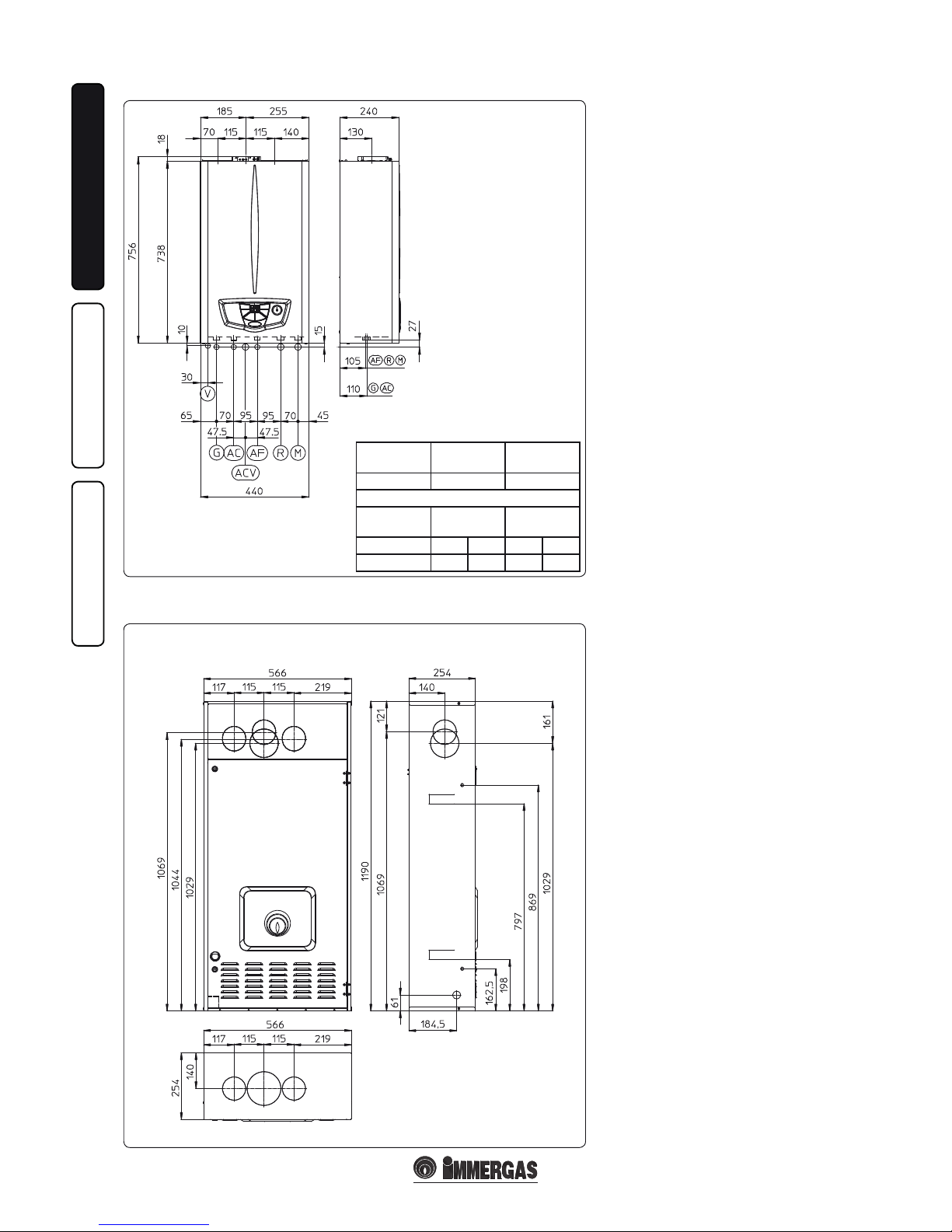
1.2 MAIN DIMENSIONS.
1.3 MAIN DIMENSIONS
RECESSING KIT OPTIONAL.
Key:
G - Gas supply
AC - Domestic hot water outlet
ACV - Domestic hot water inlet
solar valve kit (Optional)
AF - Domestic cold water inlet
R - System return
M - System delivery
V - Electric attachment
N.B.: connection group
(optional)
1.4 ANTIFREEZE PROTECTION.
Minimum temperature -5°C. e boiler is sup-
plied with an antifreeze function as standard that
activates the pump and burner when the system
water temperature in the boiler falls below 4°C.
e antifreeze function is only guaranteed if:
- the boiler is correctly connected to gas and
electricity power supply circuits;
- the boiler is powered constantly;
- the boiler is not in no ignition block (Parag.
2.4);
- the boiler essential components are not faulty.
In these conditions the boiler is protected against
freezing to an env ironmental temperature of -5°C.
Minimum temperature -15°C. If the boiler is
installed in a place where the temperature falls
below -5°C, and in the event there is no gas (or
the boiler goes into ignition block), the appliance
can freeze.
To prevent the risk of freezing follow the instructions below:
- Protect the heating circuit from freezing by
adding a high quality anti-freeze liquid that is
not considered a health hazard. It is necessary
to carefully follow manufacturer instructions
regarding this liquid when considering the
percentage necessary that depends on the minimum temperature the system is to be protected
from. An aqueous solution must be prepared
with a potential water pollution potential of 2
(EN 1717:2002).
e materials that Immergas boilers are made
from are resistant to ethylene and propylene glycolbased anti-freeze liquids (If the mixtures have been
prepared according to industry standards).
For life and possible disposal, follow the supplier’s
instructions.
- Protect the condensate drain trap and circuit
board against freezing by using an accessory
that is supplied on request (antifreeze kit)
comprising two electric heating elements,
the relevant cables and a control thermostat
(carefully read the installation instructions
contained in the accessory kit pack).
Boiler anti-freezing protection is thus ensured
only if:
- the boiler is correctly connected to electricity
power supply circuits;
- Main switch is inserted;
- the anti-freeze kit components are ecient.
In these conditions the boiler is protected against
freezing to temperature of -15°C.
e warranty does not cover damage due to interruption of the electrical power supply and failure
to comply with that stated on the previous page.
N.B.: if the boiler is installed in places where
the temperature falls below 0°C, the heating
attachment pipes must be insulated.
1.5 ATTACHMENTS.
Gas connection (Appliance category II
2H3+
).
Our boilers are designed to operate with methane
gas (G20) and LPG. Supply pipes must be the
same as or larger than the 3/4”G boiler tting.
Before connecting the gas line, carefully clean
inside all the fuel feed system pipes to remove any
residue that could impair boiler eciency. Also
make sure the gas corresponds to that for which
the boiler is prepared (see boiler data-plate). If
dierent, the appliance must be converted for
operation with the other type of gas (see converting appliance for other gas types). e dynamic
Height
(mm)
Widt h
(mm)
Depth
(mm)
756 440 240
ATTACHMENTS
GAS
DOMESTIC
HOT WATER
PLANT
GACAFRM
3/4” 1/2” 1/2” 3/4” 3/4”
1-6
1-5
5 - IE
INSTALLATORUSERTECHNICIAN
gas supply (methane or LPG) pressure must also
be checked according to the type used in the
boiler, as insucient levels can reduce generator
output and cause malfunctions.
Ensure correct gas cock connection. e gas
supply pipe must be suitably dimensioned according to current regulations in order to guarantee
correct gas ow to the boiler even in conditions
of maximum generator output and to guarantee
appliance eciency (technical specications).
e coupling system must conform to standards.
Combustible gas quality. e appliance has been
designed to operate with gas free of impurities;
otherwise it is advisable to t special lters upstream from the appliance to restore the purity
of the gas.
Storage tanks (in case of supply from LPG
depot).
- New LPG storage tanks may contain residual
inert gases (nitrogen) that degrade the mixture
delivered to the appliance casing functioning
anomalies.
- Due to the composition of the LPG mixture,
layering of the mixture components may occur
during the period of storage in the tanks. is
can cause a variation in the heating power of
the mixture delivered to the appliance, with
subsequent change in its performance.
Hydraulic attachment.
Important: In order not to void the warranty
before making the boiler connections, carefully
clean the heating system on the primary heat
exchanger (pipes, radiators, etc.) with special
pickling or de-scaling products to remove any
deposits that could compromise correct boiler
operation.
In compliance with Standards in force it is mandatory to treat the water in the heating system
chemically in order to protect the system and
appliance from deposits of lime scale.
Water connections must be made in a rational
way using the couplings on the boiler template.
e boiler safety valves outlet must be connected
to a draining funnel. Otherwise, the manufacturer declines any responsibility in case of ooding
if the drain valves cut in.
Important: to preserve the duration of appliance
eciency features, in the presence of water whose
features can lead to the deposit of lime scale,
installation of the “polyphosphate dispenser” kit
is recommended. On the basis of the Standards in
force, it is mandatory to treat the water with over
25 French degrees in the heating circuit and over
15 French degrees for DHW using conditioning
chemicals for powers < 100 kW or with soeners
for powers > 100 kW.
Electrical connection: e “Eolo Star 24 3 E”
boiler has an IPX5D protection rating for the
entire appliance. Electrical safety of the unit is
reached when it is correctly connected to an
ecient earthing system as specied by current
safety standards.
Important: Immergas S.p.A. declines any
responsibility for damage or physical injury
caused by failure to connect the boiler to an
ecient earth system or failure to comply with
the reference standards.
Also ensure that the electrical installation
corresponds to maximum absorbed power
specications as shown on the boiler data-plate.
e boilers are supplied complete with an “X”
type power cable without plug. e power supply cable must be connected to a 230V ±10% /
50Hz mains supply respecting L-N polarity and
earth connection
, is network must also
have a multi-pole circuit breaker with class III
over-voltage category. When replacing the power
supply cable, contact a qualied technician (e.g.
the Immergas Aer-Sales Technical Assistance
Service). e power cable must be laid as shown.
In the event of mains fuse replacement on the
control board, use a 3.15A quick-blow fuse. For
the main power supply to the appliance, never
use adapters, multiple sockets or extension leads.
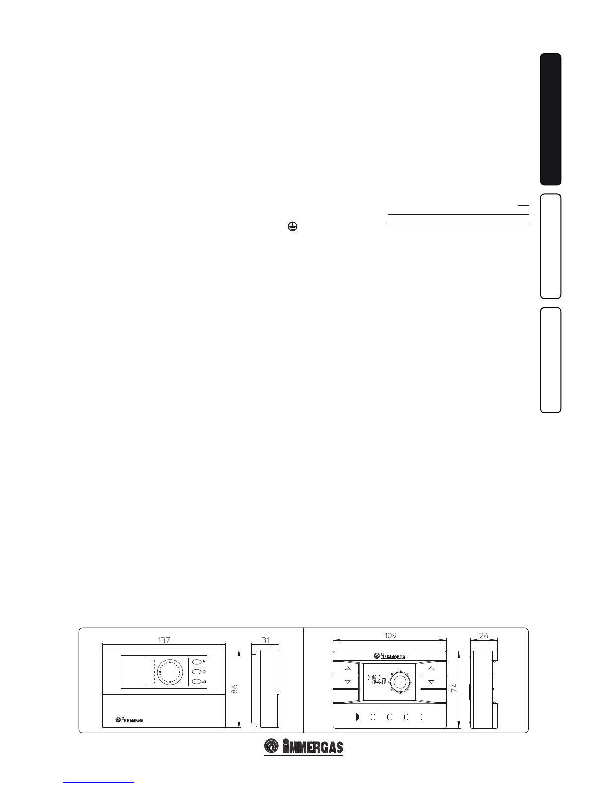
1.6 REMOTE CONTROLS AND
ROOM CHRONOTHERMOSTATS
OPTIONAL.
La caldaia è predisposta per l’applicazione dei
cronotermostati ambiente o dei comandi remoti
che sono disponibili come kit optional.
All Immergas chronothermostats are connected with 2 wires only. Carefully read the user
and assembly instructions contained in the
accessory kit.
• On/O digital chronothermostat (Fig. 1-5). e
chronothermostat allows:
- setarea a două valori de temperatură ambient:
set two room temperature values: one for day
(comfort temperature) and one for night
(lower temperature);
- set up to four on/o dierential weekly pro-
grams;
- select the desired function mode from the
various possible alternatives:
• permanent functioning in comfort temp.
• permanent functioning in reduced temp.
• permanent functioning in adjustable anti-
freeze temp.
e chronothermostat is powered by two 1.5V
LR 6 type alkaline batteries;
• Digital Remote Control Device with climate
chronothermostat function (Fig. 1.6). In addition to the functions described in the previous
point, the Digital Remote Control panel enables
the user to control all the important information regarding operation of the appliance and
the heating system with the opportunity of
easily intervening on the previously set parameters without having to go to the place where
the appliance is installed. e Digital Remote
Control panel is provided with self-diagnosis to
display any boiler functioning anomalies. e
climate chronothermostat incorporated into
the remote panel enables the system delivery
temperature to be adjusted to the actual needs
of the room being heated, in order to obtain
the desired room temperature with extreme
precision and therefore with evident saving in
running costs. e chronothermostat is fed
directly by the boiler by means of the same 2
wires used for the transmission of data between
boiler and chronothermostat.
Digital Remote Control or On/O chronothermostat electrical connections (Optional). e
operations described below must be performed after having removed the voltage from the appliance.
Any thermostat or On/O environment chronothermostat must be connected to clamps 40
and 41 eliminating jumper X40 (Fig. 3-2). Make
sure that the On/O thermostat contact is of the
“clean” type, i.e. independent of the mains supply;
otherwise the electronic adjustment card would
be dam age d. e Di gi tal Rem ote Con tro l mu st b e
connected to clamps 40 e 41 eliminating jumper
X40 on the P.C.B. (in the boiler), (Fig. 3-2).
Important: If the Digital Remote Control is used,
arrange two separate lines in compliance with
current regulations regarding electrical systems.
No boiler pipes must ever be used to earth the
electric system or telephone lines. Ensure elimination of this risk before making the boiler
electrical connections.
1-7
1-8
6 - IE
INSTALLATORUSERTECHNICIAN
1.7 IMMERGAS FLUE SYSTEMS.
Immergas supplies various solutions separately
from the boiler regarding the installation of air
intake terminals and ue extraction, which are
fundamental for boiler operation.
Important: e boiler must only be installed
together with an original Immergas air intake
and fume extraction system. is system can be
identied by an identication mark and special
distinctive marking bearing the note: “not for
condensing boilers”.
e ue exhaust pipes must not be in contact with
or be near to ammable materials. Moreover,
they must not pass through buildings or walls
made of ammable material.
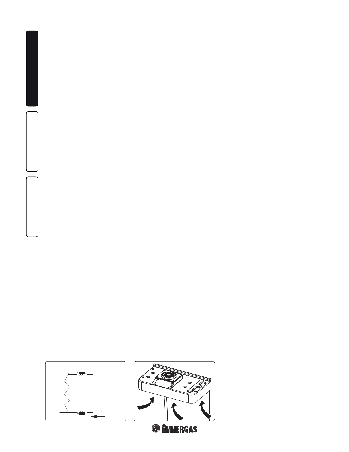
Positioning of double lip seals. For correct
positioning of lip seals on elbows and extensions,
follow the direction of assembly given in gure
(Fig. 1-7).
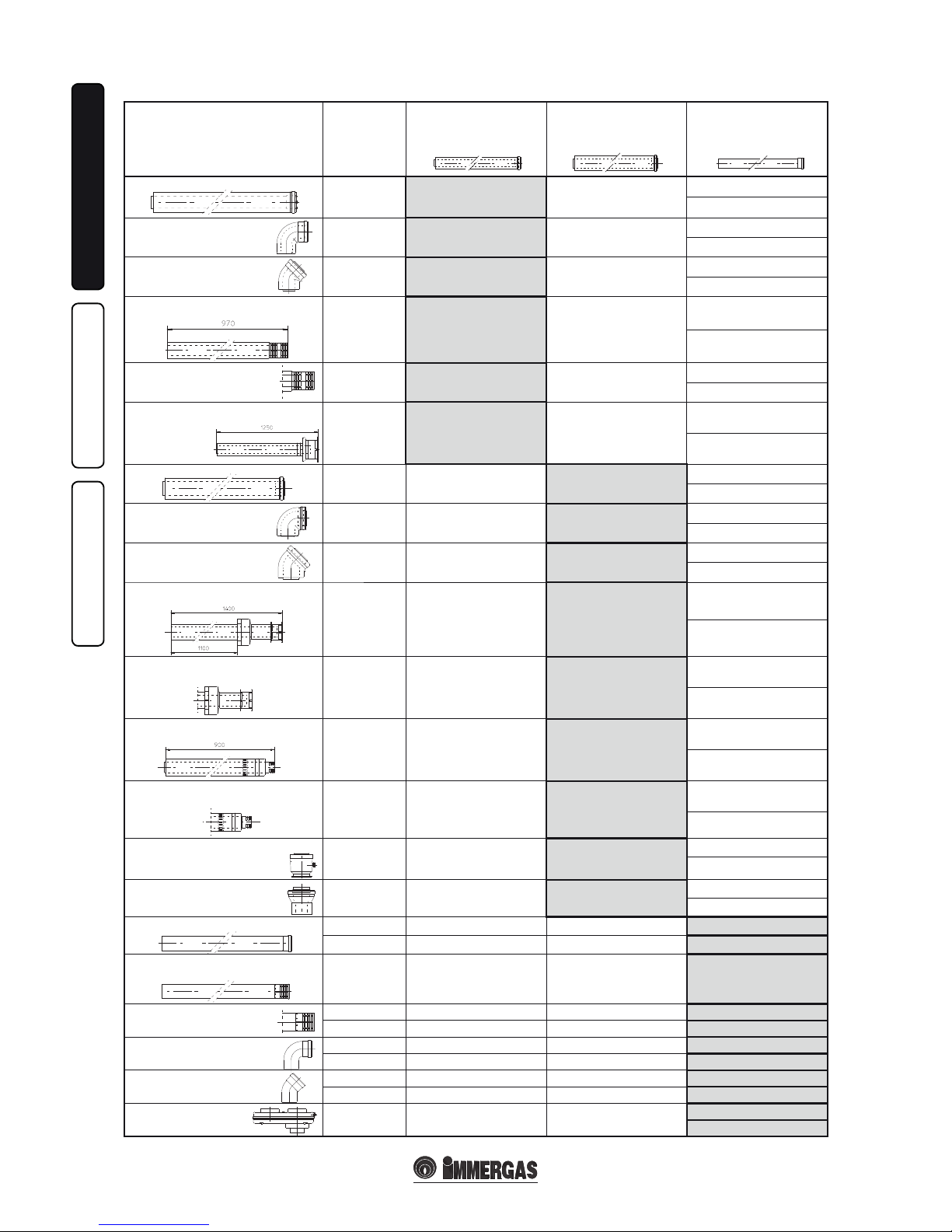
• Resistance factors and equivalent lengths.
Each ue extraction system component has a
Resistance Factor based on experimental tests
and specied in the table below. e resist ance
factor for individual components does not
depend either on the type of boiler on which
it is installed or the actual dimensions. It is,
however, conditioned by the temperature of the
uids that pass through the pipe and therefore
varies according to applications for air intake
or ue exhaust. Each single component has a
resistance corresponding to a certain length
in metres of pipe of the same diameter; the
so-called equivalent length, obtained from the
ration between he relative Resistance Factors.
All boilers have an experimentally obtainable
maximum Resistance Factor equal to 100.e
maximum Resistance Factor allowed corresponds to the resistance encountered with the
maximum allowed pipe length for each type
of Terminal Kit. This information enables
calculations to be made in order to verify the
possibility of various congurations of ue
extraction systems.
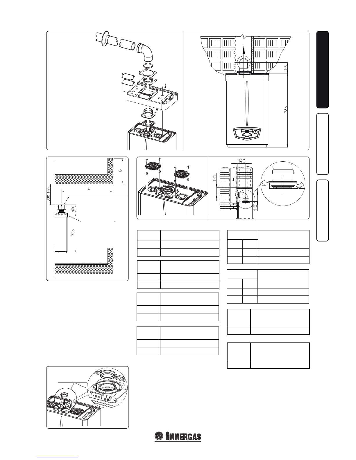
1.8 OUTDOOR INSTALLATION IN
PARTIALLY PROTECTED AREA.
N.B.: a partially protected area is one in which the
appliance is not exposed to the direct action of the
weather (rain, snow, hail, etc...).
• Conguration with cover kit and direct air
intake (boiler type C).
Using the relevant cover kit, direct air intake is
possible and fumes are exhausted into a single
ue or directly to the outside (Fig. 1-8).
Diaphragm installation. For correct functioning
of the boiler congured with direct air intake, it
is necessary to install a diaphragm on the outlet
of the sealed chamber and before the diaphragm
exhaust pipe Ø 38 (Fig. 1-14).
• Cover kit assembly (Fig. 1-9). Remove the
two plugs and the gaskets present from the two
lateral holes with respect to the central one.
Install the Ø 80 outlet ange on the central hole
of the boiler, taking care to insert the gasket
supplied with the kit and tighten by means of
the screws provided. Install the upper cover,
xing it using the 4 screws present in the kit,
positioning the relevant gaskets. Engage the 90°
Ø 80 bend with the male end (smooth) in the
female end (with lip seal) of the Ø 80 ange unit
until it stops. Introduce the gasket, making it
run along the bend. Fix it using the sheet steel
plate and tighten by means of the straps present
in the kit, making sure to block the 4 gasket
aps. Fit the male end (smooth) of the exhaust
terminal into the female end of the bend 90° Ø
80, making sure that the relevant wall sealing
plate is already tted; this will ensure hold and
joining of the elements making up the kit.
• Coupling of extension pipes. To install snap-t
extensions with other elements of the fume
extraction elements assembly, proceed as follows: Couple the pipe or elbow with the male
side (smooth) on the female side (with lip seal)
to the end stop on the previously installed
element. is will ensure sealing eciency of
the coupling.
Max. length of exhaust ue. e ue pipe (vertical or horizontal) can be extended to a max. length
of 12 m straight route, using insulated pipes (Fig.
1-31). To prevent problems of fume condensate
in the exhaust pipe Ø 80, due to fume cooling
through the wall, the length of the pipe (not insu-
lated) must be limited to just 5 m.
Example of installation with direct vertical
terminal in partially protected location. When
the vertical terminal for direct discharge of
combustion fumes is used, a minimum gap of
300 mm must be le between the terminal and
the balcony above. e height A + B (always with
respect to the balcony above), must be equal to
or less than 2000 mm (Fig. 1-11).
• Conguration without cover kit (boiler type
C).
By leaving the side plugs tted, it is possible to
install the appliance externally, in partially covered places, without the cover kit. Installation
takes place using the Ø60/100 and Ø80/125
concentric horizontal intake/ exhaust kits. Refer
to the paragraph relative to indoor installation. In
this conguration the upper cover kit guarantees
additional protection for the boiler. It is recommended but not compulsory.
1.9 OUTDOOR INSTALLATION USING
RECESSED FRAME WITH DIRECT
AIR INTAKE.
For this conguration, use the appropriate spacers (included in the attachment kit) and place
them under the side plugs of the sealed chamber.
Air intake takes place directly from the external
environment (the recessed frame is thus ventilated) and ue exhaust in the ue or outdoors.
e boiler in this conguration, following mounting
instructions stated below, is classed as type C.
In this conguration, the ue exhaust must be
connected to its own individual ue or channelled directly into the external atmosphere.
The technical regulations in force must be
respected.
Max. length of exhaust ue. e exhaust duct
(vertical or horizontal) can be extended to a max.
of 5 straight metres in order to prevent problems
of fume condensation owing to their cooling
through the wall.
Diaphragm installation. For correct functioning
of the boiler, referring to installation with direct
air intake (type C if outdoors, type B22 if indoors), a diaphragm must be installed on the outlet
of the sealed chamber and before the diaphragm
exhaust pipe Ø 38.
N.B.: the diaphragm is supplied together with
the boiler (Fig. 1-14).
• Spacer installation. For installation with direct
air intake, type C is used outdoors, type B22
is used indoors. e 4 spacers (available as
optional inside the attachment kit) should be
inserted between the boiler and the two plugs
of the sealed chamber so that air can reach the
boiler directly from the place of installation
(Fig. 1-12 and 1-13).
• Coupling of extension pipes. To install
snap-t extensions with other elements of the
fume extraction elements assembly, proceed
as follows: Install the pipe or elbow with the
male side (smooth) in the female section (with
lip seal) to the stop on the previously installed
element. is will ensure sealing eciency of
the coupling.
1-11
1-10
1-13
1-14
1-12
1-9
7 - IE
INSTALLATORUSERTECHNICIAN
Diaphragm installation. For correct functio-
ning of the boiler it is necessary to install a diaphragm on the outlet of the sealed chamber and
before the intake and exhaust pipe (Fig. 1-14).
e choice of suitable diaphragm takes place on
the basis of the type of pipe and its maximum
extension: this calculation can be carried out
using the following tables:
N.B.: the diaphragms are supplied together with
the boiler.
VERTICAL TERMINAL KIT FOR DIRECT DRAINING
INTAKE COVER KIT
DIAPHRAGM
Diaphragm
Extension in meters
pipe Ø 60/100 horizontal
Ø 38 From 0 to 1
Ø 42.5 Exceeding 1
Diaphragm
Pipe extension in metres Ø
60/100 vertical
Ø 38 From 0 to 3.2
Ø 42.5 Exceeding 3.2
Diaphragm
Pipe extension in metres Ø
80/125 horizontal
Ø 38 From 0 to 3.3
Ø 42.5 Exceeding 3.3
Diaphragm
Pipe extension in metres Ø
80/125 vertical
Ø 38 From 0 to 8.1
Ø 42.5 Exceeding 8.1
Diaphragm
*Extension in metres
vertical pipe Ø 80
without bends
exhaust intake
- Ø 45 From 0 to 18
Ø 42.5 - From 14 to 40
Diaphragm
*Extension in metres
horizontal pipe Ø 80
with two bends
exhaust intake
- Ø 45 From 0 to 14
Ø 42.5 - From 14 to 35
Diaphragm
intake
**Extension in metres
horizontal pipe Ø 80 with
two bends
Ø 45 From 0 to 27
Diaphragm
intake
**Extension in metres
vertical pipe Ø 80
without bends
Ø 45 From 0 to 27
* ese maximum extension values are considered
intake with 1 metre drain pipe.
** ese maximum extension values are considered
exhaust with 1 metre intake pipe.
8 - IE
INSTALLATORUSERTECHNICIAN
DUCT TYPE
Resistance
Factor
(R)
Equivalent
length in m of concentric
pipe
Ø 60/100
Equivalent
length in m of concentric
pipe
Ø 80/125
Equivalent
length
in m of pipe
Ø 80
Concentric pipe Ø 60/100 m 1
Intake and
Exhaust 16,5
m 1 m 2,8
Intake m 7,1
Exhaust m 5,5
Concentric bend 90° Ø 60/100
Intake and
Exhaust 21
m 1,3 m 3,5
Intake m 9,1
Exhaust m 7,0
Concentric bend Ø 60/100
Intake and
Exhaust 16,5
m 1 m 2,8
Intake m 7,1
Exhaust m 5,5
Terminal complete with concentric
horizontal
intake-exhaust Ø 60/100
Intake and
Exhaust 46
m 2,8 m 7,6
Intake m 20
Exhaust m 15
Terminal complete with concentric
horizontal intake-exhaust Ø 60/100
Intake and
Exhaust 32
m 1,9 m 5,3
Intake m 14
Exhaust m 10,6
Terminal complete with concentric vertical
intake-exhaust Ø 60/100
Intake and
Exhaust 41,7
m 2,5 m 7
Intake m 18
Exhaust 14
Concentric pipe Ø 80/125 m 1
Intake and
Exhaust 6
m 0,4 m 1,0
Intake m 2,6
Exhaust m 2,0
Concentric bend Ø 80/125
Intake and
Exhaust 7,5
m 0,5 m 1,3
Intake m 3,3
Exhaust m 2,5
Concentric bend Ø 80/125
Intake and
Exhaust 6
m 0,4 m 1,0
Intake m 2,6
Exhaust m 2,0
Terminal complete with concentric vertical
intake-exhaust Ø 80/125
Intake and
Exhaust 33
m 2,0 m 5,5
Intake m 14,3
Exhaust m 11,0
Terminal complete with concentric vertical
intake-exhaust Ø 80/125
Intake and
Exhaust 26,5
m 1,6 m 4,4
Intake m 11,5
Exhaust m 8,8
Terminal complete with concentric
horizontal
intake-exhaust Ø 80/125
Intake and
Exhaust 39
m 2,3 m 6,5
Intake m 16,9
Exhaust m 13
Terminal complete with horizontal
intake-exhaust Ø 80/125
Intake and
Exhaust 34
m 2,0 m 5,6
Intake m 14,8
Exhaust m 11,3
Concentric adapter from Ø 60/100 to Ø
80/125 with condensate trap
Intake and
Exhaust 13
m 0,8 m 2,2
Intake m 5,6
Exhaust m 4,3
Concentric adapter from
Ø 60/100 al Ø 80/125
Intake and
Exhaust 2
m 0,1 m 0,3
Intake m 0,8
Exhaust m 0,6
Pipe Ø 80 m 1 (with and without insulation)
Intake 2,3 m 0,1 m 0,4 Intake m 1,0
Scarico 3 m 0,2 m 0,5 Exhaust m 1,0
Complete air intake terminal Ø 80 m 1
(with or without insulation)
Intake 5 m 0,3 m 0,8 Intake m 2,2
Intake terminal Ø 80
Exhaust terminal Ø 80
Intake 3 m 0,2 m 0,5 Intake m 1,3
Scarico 2,5 m 0,1 m 0,4 Exhaust m 0,8
Bend 90° Ø 80
Intake 5 m 0,3 m 0,8 Intake m 2,2
Scarico 6,5 m 0,4 m 1,1 Exhaust m 2,1
Bend 45° Ø 80
Intake 3 m 0,2 m 0,5 Intake m 1,3
Scarico 4 m 0,2 m 0,6 Exhaust m 1,3
Parallel split Ø 80
from Ø 60/100 to Ø 80/80
Intake and
Exhaust 8,8
m 0,5 m 1,5
Intake m 3,8
Exhaust m 2,9
Tables of Resistance Factors and Equivalent Lengths.
C12
1-15
C12
C12
C12
C12
1-16
1-18
1-19
1-17
1
3
2
4
5
9 - IE
INSTALLATORUSERTECHNICIAN
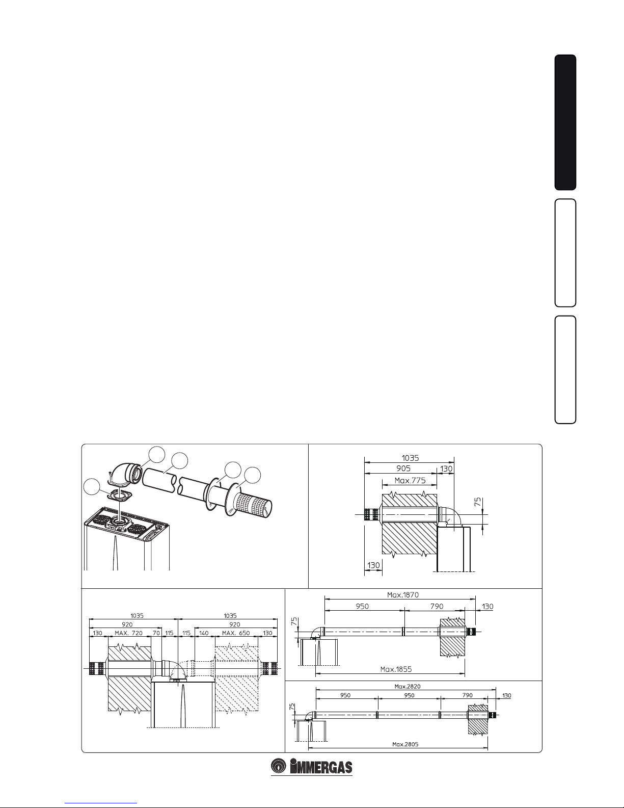
1.10 INDOOR INSTALLATION.
• Type C conguration, sealed chamber and
forced draught.
Horizontal intake - exhaust kit Ø60/100. Kit
assembly (Fig. 1-15): install the bend with ange
(2) on the central hole of the boiler inserting the
gasket (1) and tighten using the screws in the kit.
Couple the terminal pipe (3) with the male end
(smooth) into the female end of the bend (with
lip seals) up to the stop; making sure that the internal wall sealing plate and external wall sealing
plate have been tted, this will ensure sealing
and joining of the elements making up the kit.
Note: when the boiler is installed in areas where
very rigid temperatures can be reached, a special
anti-freeze kit is available that can be installed as
an alternative to the standard kit.
• Coupling extension pipes and concentric
elbows Ø 60/100. To snap-t extensions with
other elements of the fume extraction elements,
operate as follows Install the concentric pipe
or elbow with the male side (smooth) on the
female section (with lip seal) to the end stop
on the previously installed element. is will
ensure the sealing and joining of the elements
correctly.
e Ø 60/100 horizontal intake/exhaust kit can
be installed with the rear, right side, le side and
front outlet.
• Application with rear outlet (Fig. 1-16). e
970 mm pipe length enables routing through
a maximum thickness of 775 mm. Normally
the terminal must be shortened. Calculate
the distance by adding the following values:
Part thickness + internal projection + external projection. e minimum indispensable
projection values are given in the gure.
• Application with side outlet (Fig. 1-17); Using
the horizontal intake-exhaust kit, without the
special extensions, enables routing through
a wall thickness of 720 mm with the le side
outlet and 650 with the right side outlet.
• Extensions for horizontal kit. e horizontal
intake-exhaust kit Ø 60/100 can be extended
up to a max. horizontal distance of 3,000 mm
including the terminal with grid and excluding
the concentric bend leaving the boiler. is
conguration corresponds to a resistance factor
of 100. In these cases the special extensions
must be requested.
Connection with N°1 extension (Fig. 1-18).
Max. distance between vertical boiler axis and
external wall is 1855mm.
Connection with N°2 extensions (Fig. 1-19).
Max. distance between vertical boiler axis and
external wall is 2805mm.
Horizontal intake-exhaust kit Ø 80/125 Kit
assembly (Fig. 1-20): install the bend with ange
(2) onto the central hole of the boiler inserting
the gasket (1) and tighten using the screws in the
kit. Fit the male end (smooth) of the adapter (3)
up to the stop on the female end of the bend (2)
(with lip seal). Fit the Ø 80/125 (4) concentric
terminal pipe with the male end (smooth) to the
female end of the adapter (3) (with lip gasket) up
to the stop; making sure that the internal wall
sealing plate and external wall sealing plate have
been tted, this will ensure sealing and joining
of the elements making up the kit.
• Coupling extension pipes and concentric
elbows Ø 80/125. To snap-t extensions with
other elements of the fume extraction elements,
operate as follows Install the concentric pipe
or elbow with the male side (smooth) on the
female section (with lip seal) to the end stop
on the previously installed element. is will
ensure sealing and joining of the elements
correctly.
Important: if the exhaust terminal and/or extension concentric pipe needs shortening, consider
that the internal duct must always protrude by 5
mm with respect to the external duct.
Normally the Ø 80/125 horizontal intake-exhaust
kit is used if particularly long extensions are required; the Ø 80/125 kit can be installed with the
rear, right side, le side or front outlet.
• Extensions for horizontal kit. e Ø 80/125
horizontal intake-exhaust kit can be extended
up to a max. horizontal distance of 7,300 mm
including the terminal with grid and excluding
the concentric bend leaving the boiler and the
adapter Ø 60/100 in Ø 80/125 (Fig. 1-21). is
conguration corresponds to a resistance factor
of 100. In these cases the special extensions
must be requested.
N.B.: when installing the pipes, a section clamp
with pin must be installed every 3 metres.
• External grill. N.B.: for safety purposes, do not
even temporarily obstruct the boiler intakeexhaust terminal.
e kit includes:
N°1 - Gasket (1)
N°1 - Concentric bend 90° (2)
N°1 - Intake-exhaust concentric pipe
Ø60/100 (3)
N°1 - Internal white wall sealing plate (4)
N°1 - External grey wall sealing plate (5)
 Loading...